

SAMSUNG LSC550HQ05-G Specification

SAMSUNG Confidential
MODEL
LSC550HQ-G
Doc. No
Page
1 / 28
SAMSUNG TFT-LCD
MODEL: LSC550HQ05-G
The Information described in this specification is for the first draft and can be changed without prior notice
Samsung Display Co., LTD
SAMSUNG Confidential
MODEL
LSC550HQ-G
Doc. No
Page
2 / 28
General Description
Description
This model uses a liquid crystal display (LCD) of amorphous silicon TFT as switching components. This
model is composed of a TFT LCD panel, a driver circuit, and an ass’y KIT of source PBA. This 32.0”
model has a resolution of a 1366 x 768 and can display up to 16.7 million colors with the wide viewing
angle of 89° or a higher degree in all directions. This panel is designed to support applications by
providing a excellent performance function of the flat panel display such as home-alone multimedia TFTLCD TV and a high definition TV.
General Information
Features
RoHS compliance (Pb-free)
High contrast ratio & aperture ratio with the wide color gamut
SPVA(Super patterned vertical align) mode
Wide viewing angle (±178°)
High speed response
FHD resolution (16:9)
Low power consumption
DE (Data enable) mode
The interface (2pixel/clock) of 2ch LVDS (Low voltage differential signaling)
Items
Specification
Unit
Note
Active Display Area
1209.6(H) x 680.4(V)
㎜
Switching Components
a-Si TFT Active matrix
Display Colors
1.07Billion (10bit Dithering)
color
Number of Pixels
Pixel Arrangement
1,920 × 1,080
pixel
16 : 9
RGB Horizontal Stripe
Display Mode
Normally Black
Pixel Pitch
0.210(H) X 0.630(W)
Hardness
S-POL. A/G(Haze: 2%)
SAMSUNG Confidential
MODEL
LSC550HQ-G
Doc. No
Page
3 / 28
1. Absolute Maximum Ratings
If the figures on measuring instruments exceed maximum ratings, it can cause the malfunction or the
unrecoverable damage on the device.
Item
Symbol
Min.
Max.
Unit
Note
Power supply voltage
V
DD
10.8
13.2
V
(1)
Temperature for storage
(Temperature of glass surface)
T
STG
5
40
℃
(2),(4)
Operating temperature
T
OPR
0
50
℃
(2),(5)
Humidity for storage
H
STG
35
75
%RH
(2),(4)
Operating humidity
H
STG
20
90
%RG
(2),(5)
Endurance on static electricity
150
V
(3)
Note (1) The power supply voltage at Ta= 25 ± 2 °C
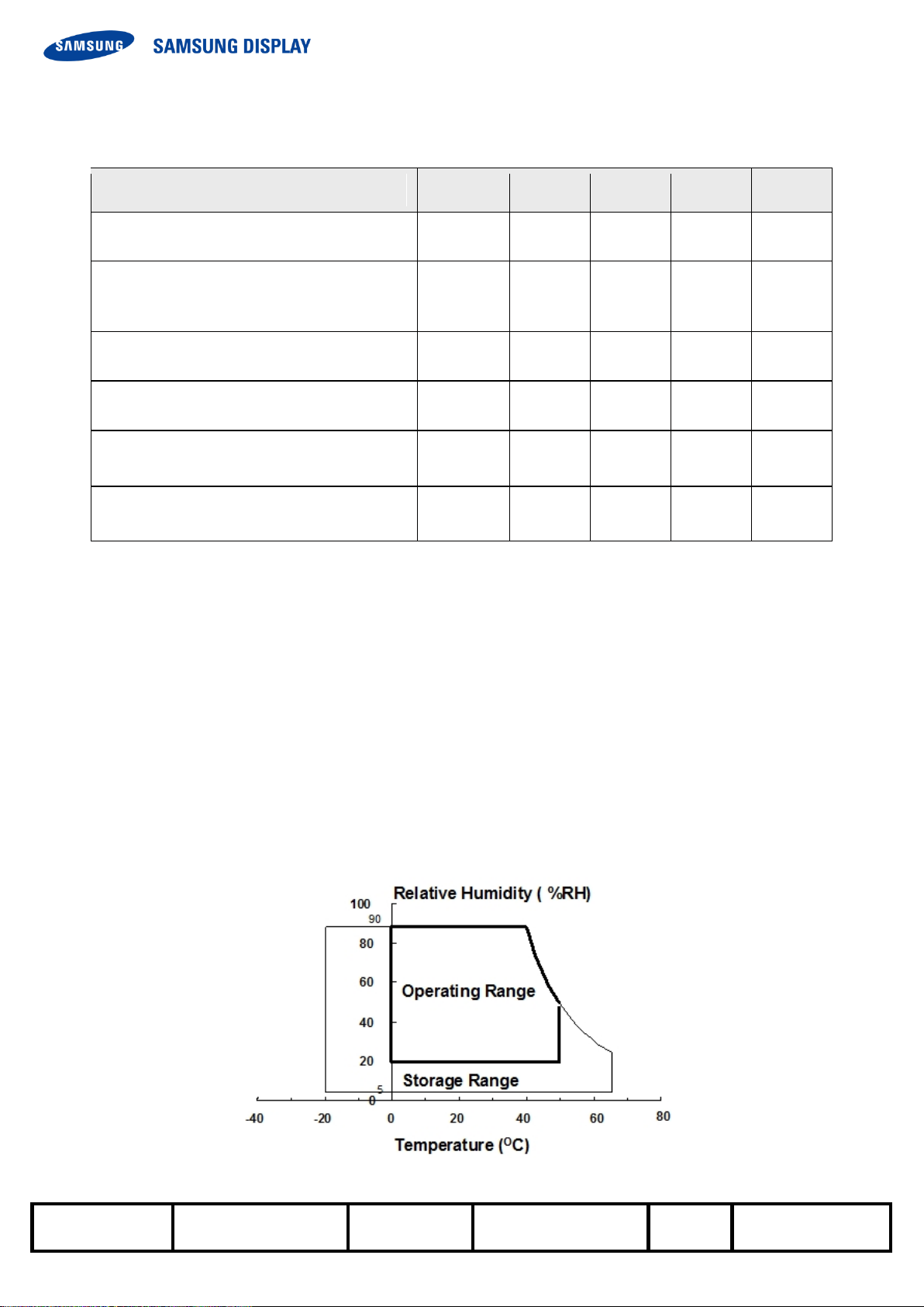
(2) Temperature and the range of relative humidity are shown in the figure below.
a. 90 % RH Max. (Ta ≤ 39 °C)
b. The relative humidity is 90% or less. (Ta >39 °C)
c. No condensation
(3) Keep the static electricity under 150V in Polarizer attaching process.
(4) Operating condition with source PCB
(5) Storage temperature condition including glass
(6) Condition without packing. (Unpacking condition)
Fig. Range for temperature and relative humidity
SAMSUNG Confidential
MODEL
LSC550HQ-G
Doc. No
Page
4 / 28
2. Optical characteristics
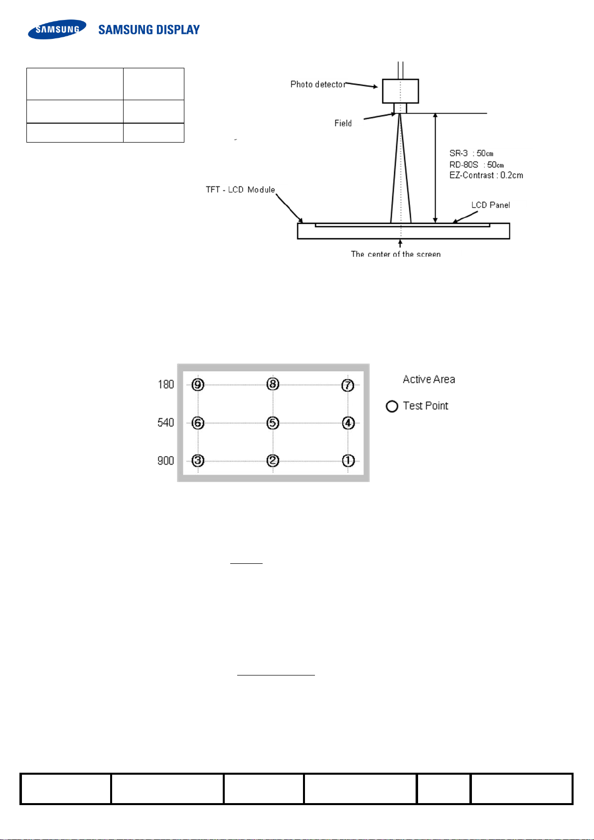
The optical characteristics should be measured in the dark room or the space surrounded by the similar setting.
Measuring equipment : TOPCON RD-80S, TOPCON SR-3 ,ELDIM EZ-Contrast
(Ta = 25 ± 2°C, VDD=12.0V, fv=60Hz, f
DCLK
=78MHz, Light source: D65 Standard light)
Item
Symbol
Condition
Min.
Typ.
Max.
Unit
Note
Contrast ratio
(At the center of screen)
C/R 3000
4000
-
(1)
SR-3
Luminance of white
(At the center of screen)
YL
Normal
qL,R=0
qU,D=0
Viewing
Angle
410
450
-
cd/m2
(4)
SR-3
Chromaticity
(CIE 1931)
Red
Rx
TYP.
-0.03
0.660
TYP.
+0.03
(5),(6)
SR-3
Ry
0.327
Green
Gx
0.280
Gy
0.580
Blue
Bx
0.132
By
0.129
White
Wx
0292
Wy
0.363
Color gamut
-
62
65 - %
(5)
SR-3
Color
- 5000
7000
9000
K
Viewing
Angle
Hor.
qL
C/R≥10
75
89
-
Degree
(6)
SR-3
EZ-Contrast
qR
75
89
-
Ver.
qU
75
89
-
qD
75
89
-
Brightness uniformity
(9 Points)
B
uni
25
%
(2)
SR-3
Gamma
1.9
2.2
2.5
(8)
SR3
transmissivity
T 5.8
6.3 %
(7)
D65/SR3
Notice
(a) Setup for test equipment
The measurement should be executed in a stable, windless, and dark room for 40min and 60min after
operating the panel at the given temperature for stabilization of the standard light. (SDC uses the standard
luminance of the D65 media).
This measurement should be measured at the center of screen.
The environment condition: Ta = 25 ± 2 °C
(b) D65 media has the general light source.
The temperature of color is 6487K. The coordinate of color is Wx 0.313, Wy 0.329
The luminance of this product is 7217cd/㎡.
SAMSUNG Confidential
MODEL
LSC550HQ-G
Doc. No
Page
5 / 28
Photo detector
Field
SR-3
2°/1°
RD-80S
1°
(c) The CIE positions D65 as the standard daylight illuminant:
[D65] is intended to represent average daylight and has a correlated color temperature of
approximately 6487 K. CIE standard illuminant D65 should be used in all colorimetric calculations
requiring representative daylight, unless there are specific reasons for using a different illuminant.
- Definition of the test point
Note (1) Definition of contrast ratio (C/R)
: The ratio of gray max (Gmax) & gray min (Gmin) at the center point ⑤ of the panel
The measurement goes in D65 Standard light source
Gmax : The luminance with all white pixels
Gmin : The luminance with all black pixels
Note (2) Definition of the brightness uniformity of 9 points (Test pattern : The full white)
The measurement shall be executed with the standard light source of D65 .
Bmax : The maximum brightness
Bmin : The minimum brightness
C R
G
G
/
max
min
Buni
B B
B
100
( max min)
max

SAMSUNG Confidential
MODEL
LSC550HQ-G
Doc. No
Page
6 / 28
Note (3) Definition of the response time : Sum of Tr, Tf
※ G-to-G : Average response time between whole gray scale to whole gray scale.
The response time is the value that was measured after it was operated in Samsung's standard BLU for
one hour.( at room temperature)
Note (4) The definition of luminance of white: The luminance of white at the center point ⑤
The measurement shall be executed with the standard light source of D65.
Note (5) The definition of chromaticity (CIE 1931)
The color coordinate of red, green, blue and white at the center point ⑤
The measurement shall be executed with the standard light source of D65.
Note (6) Definition of viewing angle
: The range of viewing angle (C/R ≥10)
The measurement shall be executed with the standard light source of D65.
Note (7) Definition of transmissivity
The measurement shall be executed with the standard light source of D65.
Note (8) Definition of Gamma
The response
Of optical instruments
Display data
Gamma X Y
X Z B B B
lum
lum
log( / )/log( / )
( ) / ( )
min max min
100 100
100
Y: Measurement Level / Z: Measurement Brightness
B
max
: Maximum Brightness / B
min
: Minimum Brightness
SAMSUNG Confidential
MODEL
LSC550HQ-G
Doc. No
Page
7 / 28
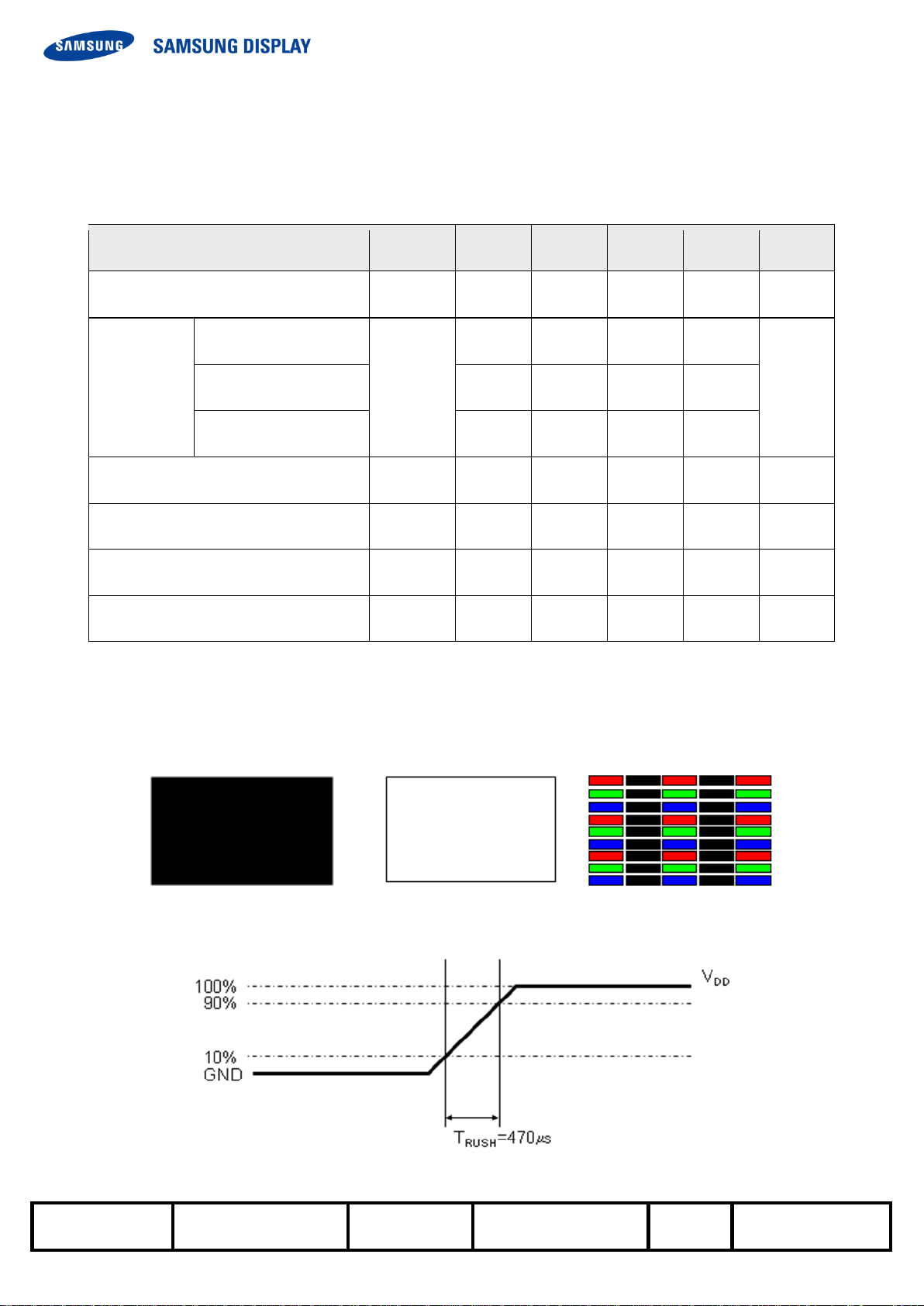
3. Electrical characteristics
3.1 TFT LCD Module
The connector for the display data & timing signal should be connected.
Ta = 25°C ± 2 °C
Item
Symbol
Min.
Typ.
Max.
Unit
Note
Voltage of power supply
V
DD
10.8
12.0
13.2
V
(1)
Current
of power
supply
(a) Black
I
DD
-
650
800
mA
(2),(3)
(b) White
-
750
950
mA
(c) Sub V-Stripe
-
1300
1700
mA
Vsync frequency
f
V
48
60
62.5
Hz
Hsync frequency
f
H
60
67.5
70
kHz
Main frequency
Fdclk
130
148.5
152.5
MHz Rush current
I
RUSH
- - 4
A
(4)
Note (1) The ripple voltage should be controlled fewer than 10% of V
DD
(Typ.) voltage.
(2) fV=60Hz, fDCLK =148.5MHz, VDD = 12.0V, DC Current.
(3) Power dissipation check pattern (LCD Module only)
(4) Conditions for measurement
a) Black pattern b) White pattern c) V-stripe
The rush current, I
RUSH
can be measured during T
RUSH
is 470us

MODEL
LSC550HQ-G
Doc. No
Page
8 / 28
4. Block diagram
SAMSUNG Confidential
SAMSUNG Confidential
MODEL
LSC550HQ-G
Doc. No
Page
9 / 28
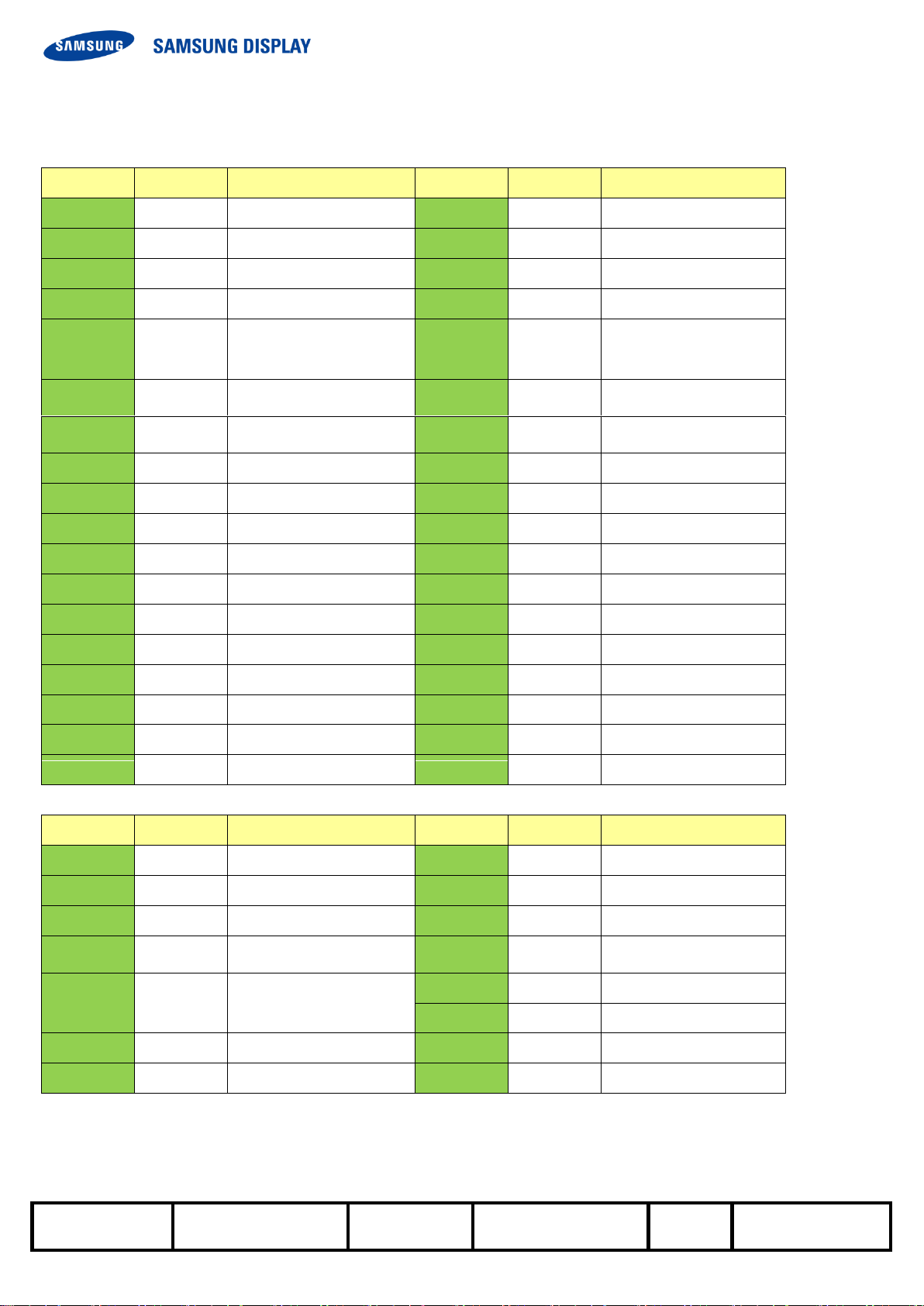
5. The Pin assignment in the input terminal
5.1. Input signal & power
Pin
Symbol
Description
Pin
Symbol
Description
1
TCON_WP
Bus release
19
Rx1CLK-
1st, 5thLVDS Clock -
2
SCL_I
I2C SCL
20
Rx1CLK+
1st, 5thLVDS Clock +
3
SDA_I
I2C SDA
21
GND
Ground
4
3D Format 0
Not Connect (2)
22
Rx1[D]N
1st, 5thLVDS Signal -
5
3D_SYNC_O
ShutterGlass sync
23
Rx1[D]P
1st, 5thLVDS Signal +
output signal
6
3D Format 1
Not Connect (2)
24
Rx1[E]N
1st, 5thLVDS Signal -
(1)
7
N.C
Not Connect
25
Rx1[E]P
1st, 5thLVDS Signal +
(1)
8
N.C
Not Connect (3)
26
3D_EN
3D_EN signal
9
N.C
Not Connect (3)
27
N.C
Not Connect (3)
10
N.C
Not Connect (3)
28
Rx2[A]N
2nd, 6thLVDS Signal -
11
GND
Ground
29
Rx2[A]P
2nd, 6thLVDS Signal +
12
Rx1[A]N
1st, 5thLVDS Signal -
30
Rx2[B]N
2nd, 6thLVDS Signal -
13
Rx1[A]P
1st, 5thLVDS Signal +
31
Rx2[B]P
2nd, 6thLVDS Signal +
14
Rx1[B]N
1st, 5thLVDS Signal -
32
Rx2[C]N
2nd, 6thLVDS Signal -
15
Rx1[B]P
1st, 5thLVDS Signal +
33
Rx2[C]P
2nd, 6thLVDS Signal +
16
Rx1[C]N
1st, 5thLVDS Signal -
34
GND
Ground
17
Rx1[C]P
1st, 5thLVDS Signal +
35
Rx2CLK-
2nd, 6thLVDS Clock -
18
GND
Ground
36
Rx2CLK+
2nd, 6thLVDS Clock +
Pin
Symbol
Description
Pin
Symbol
Description
37
GND
Ground
44
GND
Ground
38
Rx2[D]N
2nd, 6thLVDS Signal -
45
GND
Ground
39
Rx2[D]P
2nd, 6thLVDS Signal +
46
GND
Ground
40
Rx2[E]N
2nd, 6thLVDS Signal -
(1)
47
N.C
Not Connect
41
Rx2[E]P
2nd, 6thLVDS Signal
+ (1)
48
12V
DC power supply
49
12V
DC power supply
42
N.C
Not Connect (3)
50
12V
DC power supply
43
N.C
Not Connect (3)
51
12V
DC power supply
 Loading...