

Samsung LN-T325H Schematic

SERVICE
Manual
LCD TV
Fashion Feature
LCD-TV
Chassis Model
GBR32MUS LN-T325H
GBR37MUS LN-T375H
GBR40MUS LN-T405H
- RF, DVI-D, PC(Analog), Component, Video,
S-Video
- Brightness : 500cd/m
2
- Contrast Ratio : 32"/37"/40" => 8000:1
- Respense time : 8ms
- Dynamic contrast
- PIP (on PC only)

ii
Copyright
©2007 by Samsung Electronics Co., Ltd.
All rights reserved.
This manual may not, in whole or in part, be copied,
photocopied, reproduced, translated, or converted to
any electronic or machine readable form without prior
written permission of Samsung Electronics Co., Ltd.
LN-T325HX/LN-T375HX/LN-T405HX
Service Manual
First edition March 2007.
Printed in Korea.
Trademarks
Samsung is the registered trademark of Samsung
Electronics Co., Ltd.
LN-T325HX/LN-T375HX/LN-T405HX and
MacMaster Cable Adapter are trademarks of
Samsung Electronics Co., Ltd.
Macintosh, Power Macintosh are trademarks of Apple
Computer, Inc.
All other trademarks are the property of their respective
owners.

11 Precautions…………………………………………………………………………………………………………………………………………1-1
1-1 Safety Precautions ……………………………………………………………………………………………………………………… 1-1
1-2 Servicing Precautions …………………………………………………………………………………………………………………… 1-2
1-3 Electrostatically Sensitive Devices (ESD) Precautions ……………………………………………………………………………… 1-2
1-4 Installation Precautions ………………………………………………………………………………………………………………… 1-3
2
2 Product specifications ……………………………………………………………………………………………………………………………2-1
2-1 Features …………………………………………………………………………………………………………………………………… 2-1
2-2 LNT325H Specifications ………………………………………………………………………………………………………………… 2-2
2-3 LNT375H Specifications ………………………………………………………………………………………………………………… 2-3
2-4 LNT405H Specifications ………………………………………………………………………………………………………………… 2-4
2-5 Spec Comparison ………………………………………………………………………………………………………………………… 2-5
2-6 Option Specification ……………………………………………………………………………………………………………………… 2-6
3
3 Alignments and Adjustments ……………………………………………………………………………………………………………………3-1
3-1 General Alignment Instuction …………………………………………………………………………………………………………… 3-1
3-2 Factory Mode Adjustments ……………………………………………………………………………………………………………… 3-2
3-3 White Balance - Calibration ……………………………………………………………………………………………………………… 3-9
3-4 White Ratio (Balance) Adjustment …………………………………………………………………………………………………… 3-10
3-5 Servicing Information …………………………………………………………………………………………………………………… 3-11
4
4 Troubleshooting ……………………………………………………………………………………………………………………………………4-1
4-1 No Power ………………………………………………………………………………………………………………………………… 4-1
4-2 No Video (Analog PC Signal) …………………………………………………………………………………………………………… 4-2
4-3 No Video (HDMI - Digital Signal) ……………………………………………………………………………………………………… 4-4
4-4 No Picture (Tuner_CVBS) ……………………………………………………………………………………………………………… 4-6
4-5 No Picture (Tuner DTV TS) ……………………………………………………………………………………………………………… 4-8
4-6 No Picture(Video CVBS) ……………………………………………………………………………………………………………… 4-10
4-7 No Picture (S-Video Y/C) ……………………………………………………………………………………………………………… 4-11
4-8 No Picture(Component1, 2 : 480i, 480p, 720p, 1080i[ Y, Pb, Pr]) ………………………………………………………………… 4-13
4-9 No Sound ………………………………………………………………………………………………………………………………… 4-15
5
5 Exploded View and Parts List …………………………………………………………………………………………………………………5-1
5-1 LNT325H Exploded View ………………………………………………………………………………………………………………… 5-1
5-2 LNT325H Parts list ……………………………………………………………………………………………………………………… 5-2
5-3 LNT375H Exploded View ………………………………………………………………………………………………………………… 5-3
5-4 LNT375H Parts list ……………………………………………………………………………………………………………………… 5-4
5-5 LNT405H Exploded View ………………………………………………………………………………………………………………… 5-5
5-6 LNT405H Parts list ……………………………………………………………………………………………………………………… 5-6
Contents

66 Electrical Parts List ………………………………………………………………………………………………………………………………6-1
6-1 LNT325HAX Parts List …………………………………………………………………………………………………………………… 6-1
6-2 LNT375HAX Parts List ………………………………………………………………………………………………………………… 6-23
6-3 LNT405HAX Parts List ………………………………………………………………………………………………………………… 6-46
7
7 Block Diagram ……………………………………………………………………………………………………………………………………7-1
88 Wiring Diagram ……………………………………………………………………………………………………………………………………8-1
8-1 Wiring Diagram …………………………………………………………………………………………………………………………… 8-1
9
9 Schematic Diagrams ………………………………………………………………………………………………………………………………9-1
1
10 Operating Instructions and Installation ………………………………………………………………………………………………………10-1
10-1 Front …………………………………………………………………………………………………………………………………… 10-1
10-2 Connection Panel ……………………………………………………………………………………………………………………… 10-2
10-3 Remote Control ………………………………………………………………………………………………………………………… 10-3
1
11 Disassembly and Reassembly …………………………………………………………………………………………………………………11-1
11-1 Disassembly …………………………………………………………………………………………………………………………… 11-1
11-2 Reassembly …………………………………………………………………………………………………………………………… 11-6
1
12 Schematic Diagram………………………………………………………………………………………………………………………………12-1
12-1 Main PCB Diagram …………………………………………………………………………………………………………………… 12-1
12-2 Power PCB Layout 32" ……………………………………………………………………………………………………………… 12-4
12-3 Power PCB Layout 37" ……………………………………………………………………………………………………………… 12-5
12-4 Power PCB Layout 40" ……………………………………………………………………………………………………………… 12-6
1
13 Circuit Descriptions ………………………………………………………………………………………………………………………………13-1
13-1 Block description ……………………………………………………………………………………………………………………… 13-1
1
14 Reference Infomation ……………………………………………………………………………………………………………………………14-1
14-1 Technical Terms ……………………………………………………………………………………………………………………… 14-1
14-2 Pin Assignments ……………………………………………………………………………………………………………………… 14-4
14-3 Timing Chart …………………………………………………………………………………………………………………………… 14-6
Contents

Samsung Electronics Co.,Ltd.
416, Maetan-3Dong, Yeongtong-Gu, Suwon City,
Gyeonggi-Do, Korea, 443-742
Printed in Korea
P/N : BN82URL : http://itself.sec.samsung.co.kr/
-This Service Manual is a property of Samsung
Electronics Co., Ltd.
Any unauthorized use of Manual can be
punishedv
under applicable International
and/or domestic law.

3 Alignments and Adjustments
3-1
3 Alignments and Adjustments
3-1 General Alignment Instuction
1. Usually, a color LCD-TV needs only slight touch-up adjustment upon installation.
Check the basic characteristics such as height, horizontal and vertical sync.
2. Use the specified test equipment or its equivalent.
3. Correct impedance matching is essential.
4. Avoid overload. Excessive signal from a sweep generator might overload the front-end
of the TV. When inserting signal markers, do not allow the marker generator to distort test result.
5. Connect the TV only to an AC power source with voltage and frequency as specified on
the backcover nameplate.
6. Do not attempt to connect or disconnect any wire while the TV is turned on. Make sure
that the power cord is disconnected before replacing any parts.
7. To protect aganist shock hazard, use an isolation transformer.
3 Alignments and Adjustments
3-2
3-2 Factory Mode Adjustments
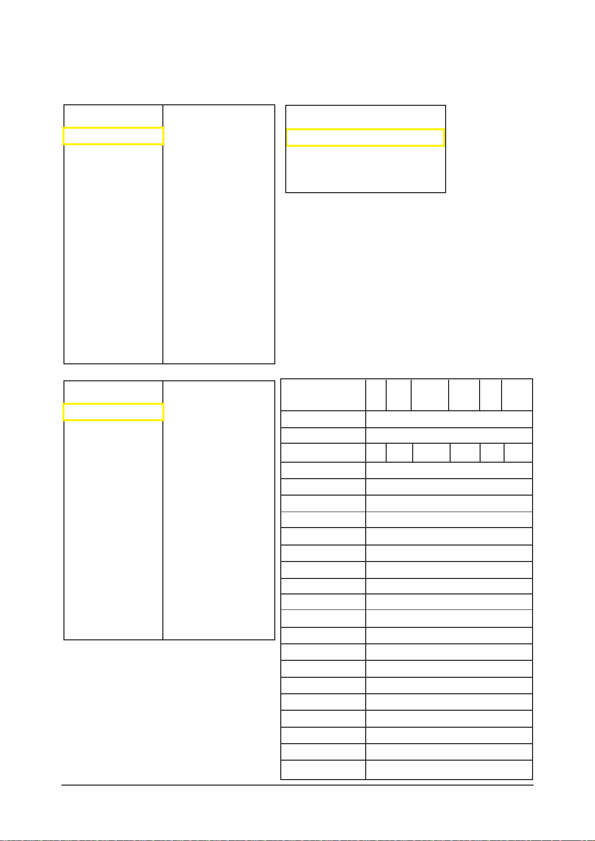
3-2-1 Entering Factory Mode
To enter 'Service Mode' Press the remote -control keys in this sequence :
- If you do not have Factory remote - control
3-2-2 How to Access Service Mode
Using the Customer Remote
1.Turn the power off and set to stand-by mode
2.Press the remote buttons in this order; POWER OFF-MUTE-1-8-2-POWER ON to turn the set on.
3.The set turns on and enters service mode.
4.Press the Power button to exit and store data in memory.
- If you fail to enter service mode, repeat steps 1 and 2 above.
5.Initial SERVICE MODE DISPLAY State
Power OFF 1 8 2 Power OnMUTE
1.Calibration
2.Option Byte
3.White Balance
4.W/B Movie
5.Calibration Target
6.Calibration Value
7.MST3388
8.X242
9.X242 NTSC
10.FBE2
11.Sound
12.Dynamic Contrast
13.Checksum 0x0000
14.Reset
T-SC37AUSC-1004
T-SC37AUSM-1002
ACL 28.20.2.1
RFS:T-SC37AUSC-20070228
2007-03-05
DTP-LO-0022
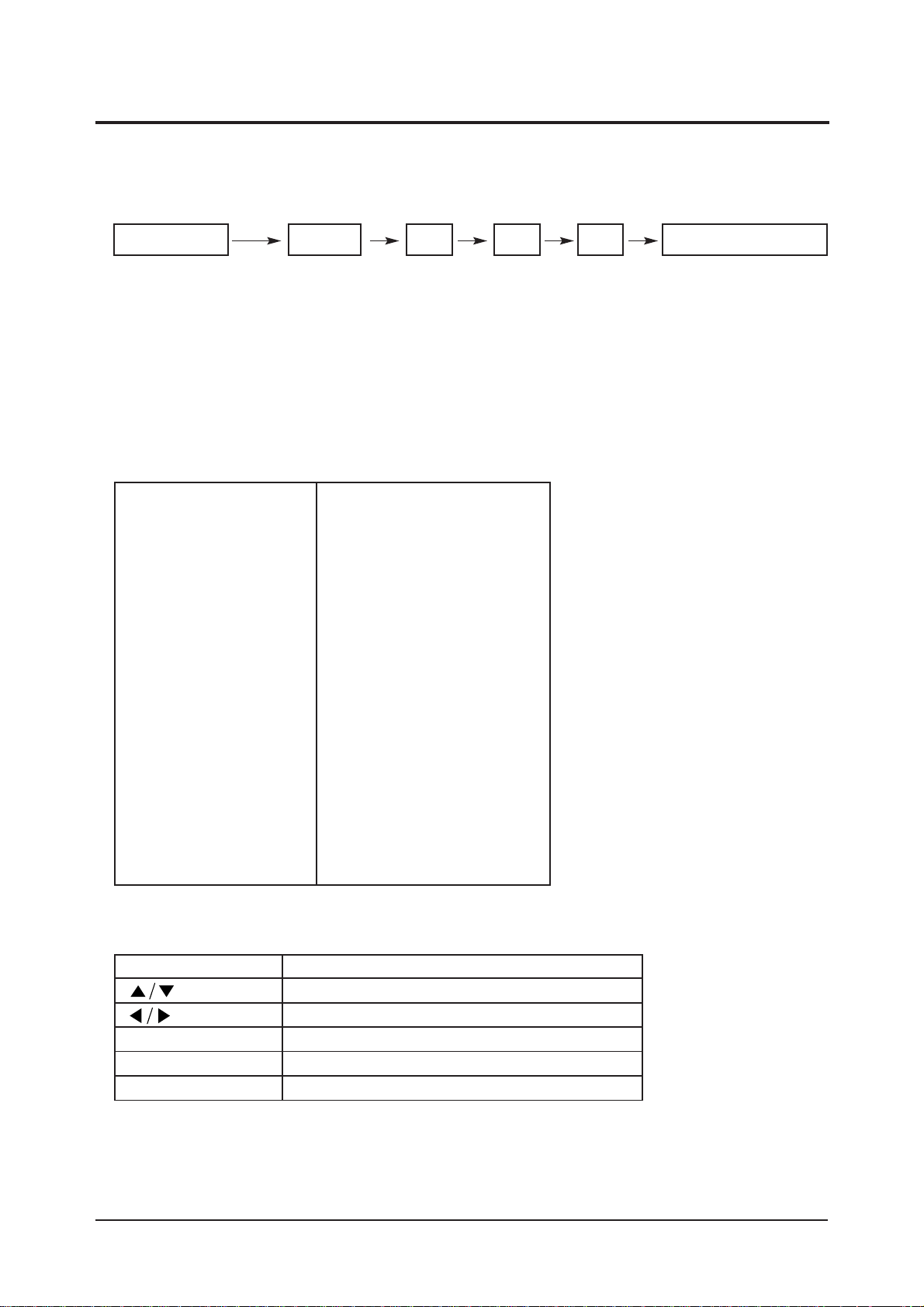
6. Buttons operations withn Service Mode
KEY
MENU
DIGIT
TV/VIDEO
FUNCTION
Item selection by moving the cursor
Data Increase/Decrease for the selected Item
Save set Data to EEPROM and go upper mode
Change channel
Change AV mode
On
On
26AU
EXT_PWM
Debug
0
XX Hr
600mS
SAMEX
OFF
OFF
OFF
OFF
Auto
Auto
1
900ms
OFF
On
60
1500
3 Alignments and Adjustments
3-3
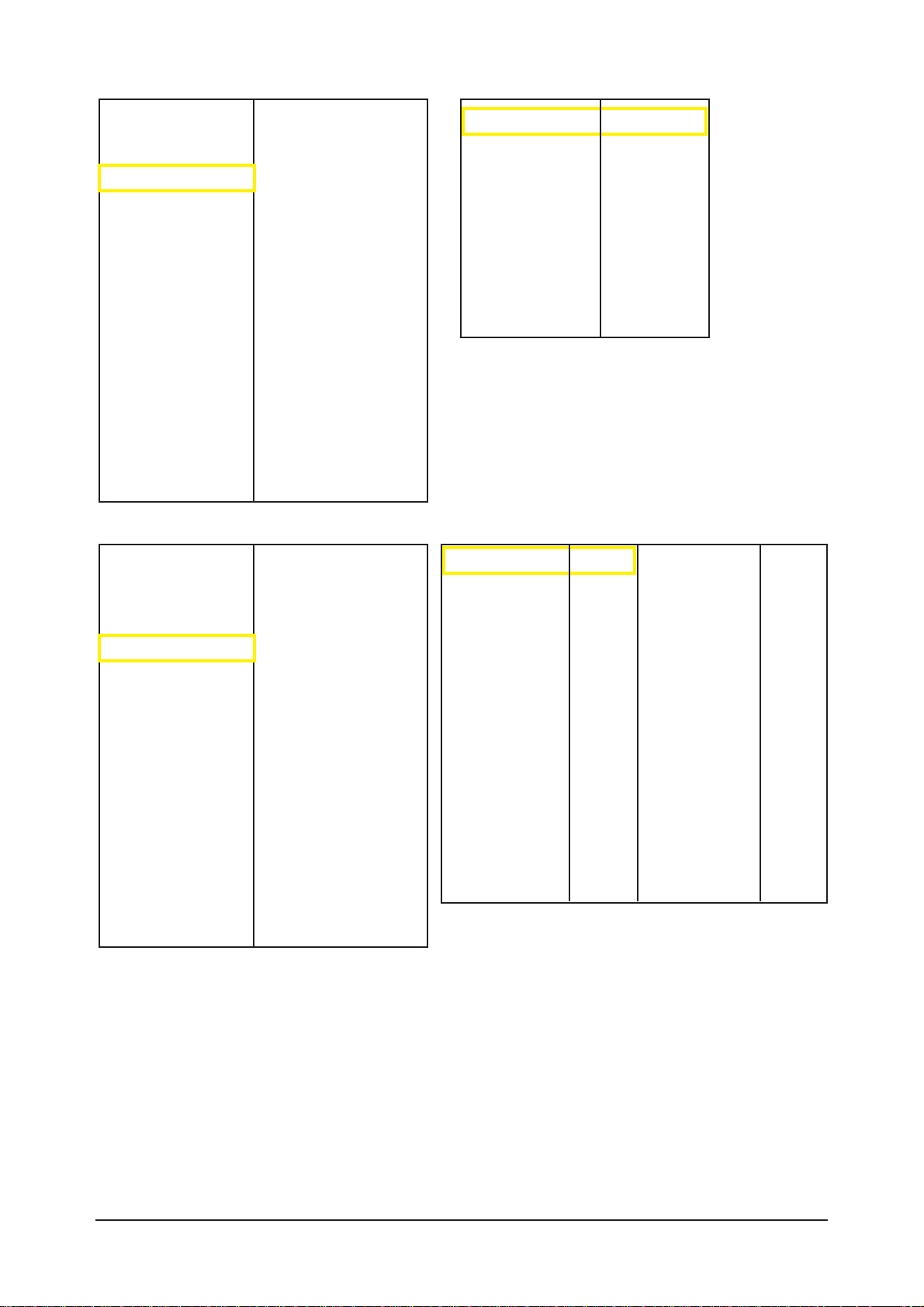
3-2-3 Factory Data
Factory Name
Caption Level
Watchdog enable
Spread Spectrum
Panel Option
Dimming
RS-232C
Gamma
Panel Display Time
Mute Time[RF]
CH Memory
Shop Mode
SUB MICOM DOWN
MAIN EEPROM WP
DDC WP
PC Mode Ident
HDMI Mode Ident
HPD Ctl Method
HPD Low Duration
Download RRT
7.5 IRE On/Off
7.5 IRE Offset
HDMI Mute Time
RF DTV
1
1
0
0
10
AV/
SVIDEO
COMP PC HDMI
1.Calibration
2.Option Byte
3.White Balance
4.W/B Movie
5.Calibration Target
6.Calibration Value
7.MST3388
8.X242
9.X242 NTSC
10.FBE2
11.Sound
12.Dynamic Contrast
13.Checksum 0x0000
14.Reset
T-SC37AUSC-1004
T-SC37AUSM-1002
ACL 28.20.2.1
RFS:T-SC37AUSC-20070228
2007-03-05
DTP-LO-0022
1.Calibration
2.Option Byte
3.White Balance
4.W/B Movie
5.Calibration Target
6.Calibration Value
7.MST3388
8.X242
9.X242 NTSC
10.FBE2
11.Sound
12.Dynamic Contrast
13.Checksum 0x0000
14.Reset
T-SC37AUSC-1004
T-SC37AUSM-1002
ACL 28.20.2.1
RFS:T-SC37AUSC-20070228
2007-03-05
DTP-LO-0022
AV Calibration
Comp Calibration
PC Calibration
Hdmi Calibration
3 Alignments and Adjustments
3-4
1.Calibration
2.Option Byte
3.White Balance
4.W/B Movie
5.Calibration Target
6.Calibration Value
7.MST3388
8.X242
9.X242 NTSC
10.FBE2
11.Sound
12.Dynamic Contrast
13.Checksum 0x0000
14.Reset
T-SC37AUSC-1004
T-SC37AUSM-1002
ACL 28.20.2.1
RFS:T-SC37AUSC-20070228
2007-03-05
DTP-LO-0022
1.Calibration
2.Option Byte
3.White Balance
4.W/B Movie
5.Calibration Target
6.Calibration Value
7.MST3388
8.X242
9.X242 NTSC
10.FBE2
11.Sound
12.Dynamic Contrast
13.Checksum 0x0000
14.Reset
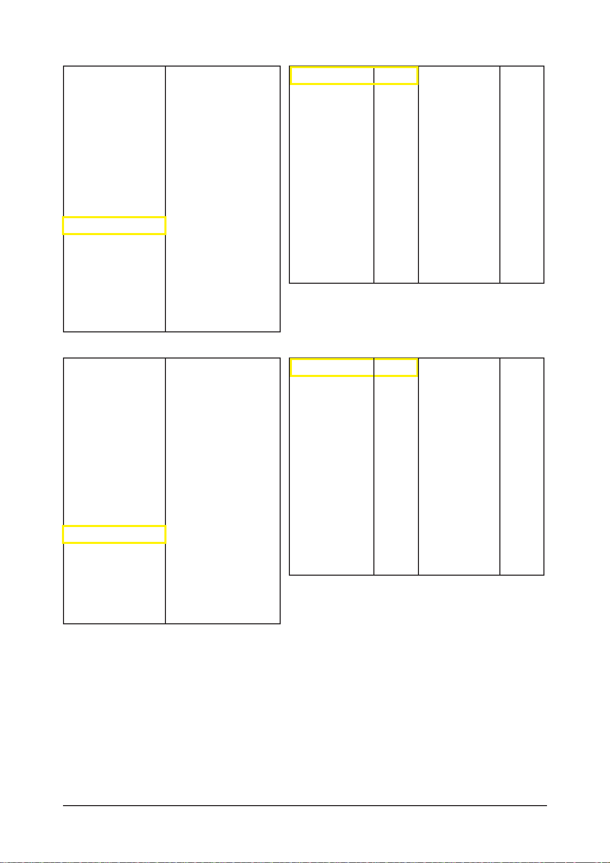
W/B Movie On/Off
Mode
Color Tone
MSub Brightness
MSub Contrast
W1_RGain
W1_BGain
W1_ROffset
W1_BOffset
W2_RGain
W2_BGain
W2_ROffset
W2_BOffset
NOR_RGain
NOR_BGain
NOR_ROffset
NOR_BOffset
C2_RGain
C2_BGain
C2_ROffset
C2_BOffset
Movie Contrast
Movie Bright
Movie Color
Movie Sharpness
on
Dynamic
Cool1
128
128
19
-26
-1
4
49
-43
-4
4
7
-11
-2
2
-32
22
5
1
70
50
25
45
T-SC37AUSC-1004
T-SC37AUSM-1002
ACL 28.20.2.1
RFS:T-SC37AUSC-20070228
2007-03-05
DTP-LO-0022
Sub Brightness
R-Offset
G-Offset
B-Offset
Sub Contrast
R-Gain
G-Gain
B-Gain
128
512
512
512
128
512
512
512

3 Alignments and Adjustments
3-5
1.Calibration
2.Option Byte
3.White Balance
4.W/B Movie
5.Calibration Target
6.Calibration Value
7.MST3388
8.X242
9.X242 NTSC
10.FBE2
11.Sound
12.Dynamic Contrast
13.Checksum 0x0000
14.Reset
1st_AV_Low
1st_AV_High
1st_AV_Delta
1st_COMP_Low
1st_COMP_High
1st_COMP_Delta
1st_PC_Low
1st_PC_High
1st_PC_Delta
2nd_AV_Low
2nd_AV_High
2nd_AV_Delta
2nd_COMP_Low
2nd_COMP_High
2nd_COMP_Delta
2nd_PC_Low
2nd_PC_High
2nd_PC_Delta
2nd_HDMI_Low
2nd_HDMI_High
2nd_HDMI_Delta
18
220
1
16
235
1
4
235
1
1
235
1
1
235
1
1
235
1
1
235
1
T-SC37AUSC-1004
T-SC37AUSM-1002
ACL 28.20.2.1
RFS:T-SC37AUSC-20070228
2007-03-05
DTP-LO-0022
1.Calibration
2.Option Byte
3.White Balance
4.W/B Movie
5.Calibration Target
6.Calibration Value
7.MST3388
8.X242
9.X242 NTSC
10.FBE2
11.Sound
12.Dynamic Contrast
13.Checksum 0x0000
14.Reset
LUMA_OFFSET
LUMA_GAIN
RED CUTOFF
GREEN CUTOFF
BLUE OFFSET
RED GAIN
GREEN GAIN
BLUE GAIN
2nd_X242_R_L
2nd_X242_G_L
2nd_X242_B_L
2nd_X242_R_H
2nd_X242_G_H
2nd_X242_B_H
501
582
-
-
-
-
-
134
134
134
1150
1150
1150
T-SC37AUSC-1004
T-SC37AUSM-1002
ACL 28.20.2.1
RFS:T-SC37AUSC-20070228
2007-03-05
DTP-LO-0022

3 Alignments and Adjustments
3-6
1.Calibration
2.Option Byte
3.White Balance
4.W/B Movie
5.Calibration Target
6.Calibration Value
7.MST3388
8.X242
9.X242 NTSC
10.FBE2
11.Sound
12.Dynamic Contrast
13.Checksum 0x0000
14.Reset
RED CUTOFF
GREEN CUTOFF
BLUE CUTOFF
PHASE_CC
RED GAIN
GREEN GAIN
BLUE GAIN
PLLDIV
PLL_GAIN
CLPDLY
CLPDUR
HSOPW
SYNC_CTRL
SOGMID_CTRL
SEP_THR
PRECST
POSTCST
ADC_BW0
ADC_BW1
RDOFFSC
GDOFFSC
BDOFFSC
126
93
125
0
200
200
200
858
1
8
8
24
64
189
32
4
14
68
4
120
0
10
T-SC37AUSC-1004
T-SC37AUSM-1002
ACL 28.20.2.1
RFS:T-SC37AUSC-20070228
2007-03-05
DTP-LO-0022
1.Calibration
2.Option Byte
3.White Balance
4.W/B Movie
5.Calibration Target
6.Calibration Value
7.MST3388
8.X242
9.X242 NTSC
10.FBE2
11.Sound
12.Dynamic Contrast
13.Checksum 0x0000
14.Reset
CH filter
CV filter
NR
UVNR
LTI-YEE
CTI-UVEE
YH_MAX
YH_Edge
YH_MIN
UVH_MAX
UVH_Edge
UVH_MIN
Color_Mid_Value
ss_CH01
Hardware
ON
OFF
ON
ON
128
4096
128
255
300
8
50
T-SC37AUSC-1004
T-SC37AUSM-1002
ACL 28.20.2.1
RFS:T-SC37AUSC-20070228
2007-03-05
DTP-LO-0022
3 Alignments and Adjustments
3-7
1.Calibration
2.Option Byte
3.White Balance
4.W/B Movie
5.Calibration Target
6.Calibration Value
7.MST3388
8.X242
9.X242 NTSC
10.FBE2
11.Sound
12.Dynamic Contrast
13.Checksum 0x0000
14.Reset
In Phase Line
In Phase Frame
Out Phase Line
Out Phase Frame
CORING
LUMA_BW
CHROMA_BW
CKILL_TH1
CKILL_TH2
LUMA_GAIN
LUNA_OFFSET
CR_GAIN
CR_OFFSET
CB_GAIN
CB_OFFSET
Y_DELAY_POS
Y_DELAY_NEG
CB_DELAY_POS
CB_DELAY_NEG
CR_DELAY_POS
CR_DELAY_NEG
AGC_ON/OFF
AGC_GAIN
24
26
12
22
2
0
4
48
80
582
501
512
0
512
0
0
12
0
13
0
13
OFF
538
T-SC37AUSC-1004
T-SC37AUSM-1002
ACL 28.20.2.1
RFS:T-SC37AUSC-20070228
2007-03-05
DTP-LO-0022
1.Calibration
2.Option Byte
3.White Balance
4.W/B Movie
5.Calibration Target
6.Calibration Value
7.MST3388
8.X242
9.X242 NTSC
10.FBE2
11.Sound
12.Dynamic Contrast
13.Checksum 0x0000
14.Reset
Patt-Sel
B-Slope gain
B-Tilt min
B-Tilt max
Lfunc-Basis
Hfunc-Basis
Mean-Offset1
Mean-Offset2
Mean-Slope
Input-offset
ACR-Offset
ACR-Th1
ACR-Th2
Skin-Enable
Skin-Tu
Skin-Tv
Sub color
M-Skin-Tu
M-Skin-Tv
M-Au-Sub color
MW-Skin-Tu
MW-Skin-Tv
M-Wi-Sub color
0
64
70
140
75
88
75
150
41
128
30
30
100
1
128
128
128
128
128
128
128
128
128
T-SC37AUSC-1004
T-SC37AUSM-1002
ACL 28.20.2.1
RFS:T-SC37AUSC-20070228
2007-03-05
DTP-LO-0022
3 Alignments and Adjustments
3-8
1.Calibration
2.Option Byte
3.White Balance
4.W/B Movie
5.Calibration Target
6.Calibration Value
7.MST3388
8.X242
9.X242 NTSC
10.FBE2
11.Sound
12.Dynamic Contrast
13.Checksum 0x0000
14.Reset
Carrier Mute
Stereo Pilot High
Stereo Pilot Low
Audio Delay
Spdif Delay
Melody Speak Vol.
Melody HP Vol.
NTP_Amp Vol.
NTP_PWM Mod.
NTP_DRC Thresh.
NTP_Speaker EQ
1
13
7
45
OFF
5
5
30
243
12
Off
T-SC37AUSC-1004
T-SC37AUSM-1002
ACL 28.20.2.1
RFS:T-SC37AUSC-20070228
2007-03-05
DTP-LO-0022
1.Calibration
2.Option Byte
3.White Balance
4.W/B Movie
5.Calibration Target
6.Calibration Value
7.MST3388
8.X242
9.X242 NTSC
10.FBE2
11.Sound
12.Dynamic Contrast
13.Checksum 0x0000
14.Reset
Dynamic CE
Dynamic Dimming
FBE2 Y_MEAN READ
Off
Off
Read Value
T-SC37AUSC-1004
T-SC37AUSM-1002
ACL 28.20.2.1
RFS:T-SC37AUSC-20070228
2007-03-05
DTP-LO-0022
3 Alignments and Adjustments
3-9
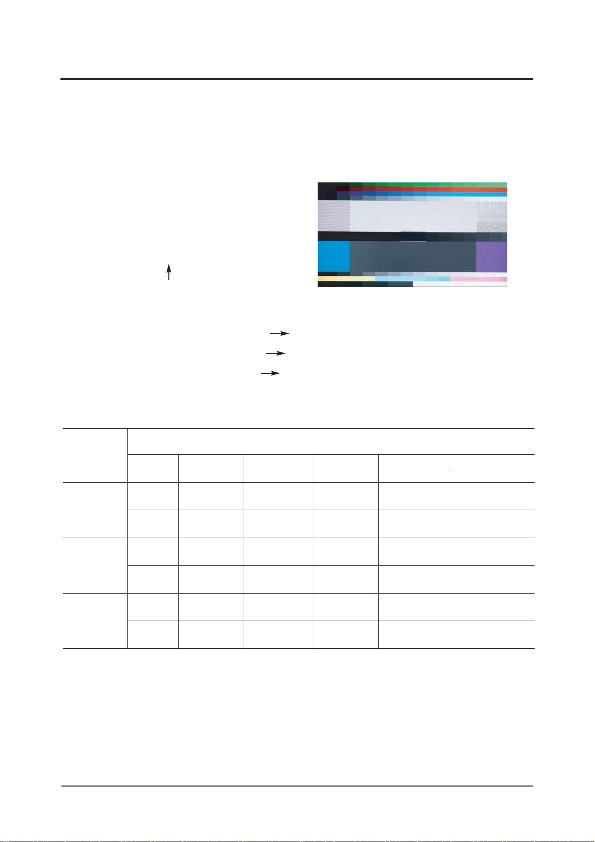
3-3 White Balance - Calibr ation
3-3-2 White Balance - Adjustment
3-3-1 White Balance -Calibration
3-3-3 Conditions for Measurement
1. Calibration
1.AV
2.DTV Calibration
3.PC Calibration
(Calibration Condition refer to next page)
4.HDMI
3. W/B
(low light) (hight light)
1. On the basis of toshiba ABL pattern : High Light level (57 IRE)
- INPUT SIGNAL GENERATOR : MSPG-925LTH
* Mode NO 1 : 744X484@60 Hz
NO 6 : 1280X720@60 Hz (Component 720P)
NO 21 : 1024X768@60 Hz
*
Pattern
NO 15 : Color bar
NO 16 : Toshiba ABL Pattern
NO 17 : 16 gray
2. Optical measuring device : CA210 (FL)
Please use the MSPG-925 LTH generator for model LNR2355W,LNR2755W,LNR3255W.
(W/B adjustment Condition refer next page)
Sub Bright Sub Contrast
R offset R gain
G offset G gain
B offset B gain
3 Alignments and Adjustments
3-10
3-4 White Ratio (Balance) Adjustment
1. You can adjust the white ratio in factory mode (1:Calibration, 3:White-Balance).
2. Since the adjustment value and the data value vary depending on the input source, you have to
adjust these in CVBS, Component 1 and HDMI 1 modes.
3. The optimal values for each mode are configured by default. (Refer to Table 1, 2.)
It varies with Panel's size and Specification.
- Equipment : CA-210
- Pattern: Master MIK K7256 #92 "ABL Pattern" as standard
- Use other equipment only after comparing the result
with that of the Master equipment.
- Set Aging time : 60min
- Calibration and Manual setting for WB adjustment.
HDMI: No Calibration Manual adjustment at #16 pattern (720p)
COMP: Calibration at #24 Chessboard Pattern Manual adjustment at #16 pattern (720p)
CVBS: Calibration at #24 Chessboard Pattern Manual adjustment at #16 pattern (NTSC)
PC : Calibration at #24 Chessboard Pattern No Manual adjustment (1024x768@60Hz)
CVBS
(NTSC)
#1, #92
L/L
H/L
H/L
L/L
H/L
L/L
T(K) + MPCD
Y (cd/m
2
)
-
-
4
4
-
4
y
278
278
278
278
278
278
CA-210
x
272
272
272
272
272
272
15000K/0
15000K/0
15000K/0
15000K/0
15000K/0
15000K/0
COMP
(720P)
#6, #92
DVI
(720P)
#6, #92
-White Balance Manual Adjustment (ABL Pattern)
-Adjustment Specification
White Balance : High light (± 3), Low light (± 5)
Luminance : High light (± 10%)
Low light (2.0fL ± 0.1fL, 2.1fL ± 0.2fL)

3 Alignments and Adjustments
3-11
3-5 Ser vicing Infor mation
3-5-1 USB Download Method
1.USB Download Method
(1) Download the upgrade file in USB flash driver.
(2) Extract the file. "T-SC37AUSC" folder will be appeared.
(3) Turn on the LCD TV.
(4) Insert the USB flash driver into the service jack of LCD TV and press the MENU button.
(5) Place the cursor to SW Upgrade of Setup MENU.
(6) Press the "ENTER" button.
(7) "Scanning for USB..... It may take up to 30 seconds." will be appeared.
(8) Press the "ENTER" button.
(9) "Upgrading now... Please do not disconnect USB before upgrade is completed." will be appeared.
(10)When upgrade is completed, the OSD says "Upgrade is completed. Power will be off 3 seconds
from now and turned on automatically.".

3 Alignments and Adjustments
3-12
Memo
7 Block Diagrams
7-1
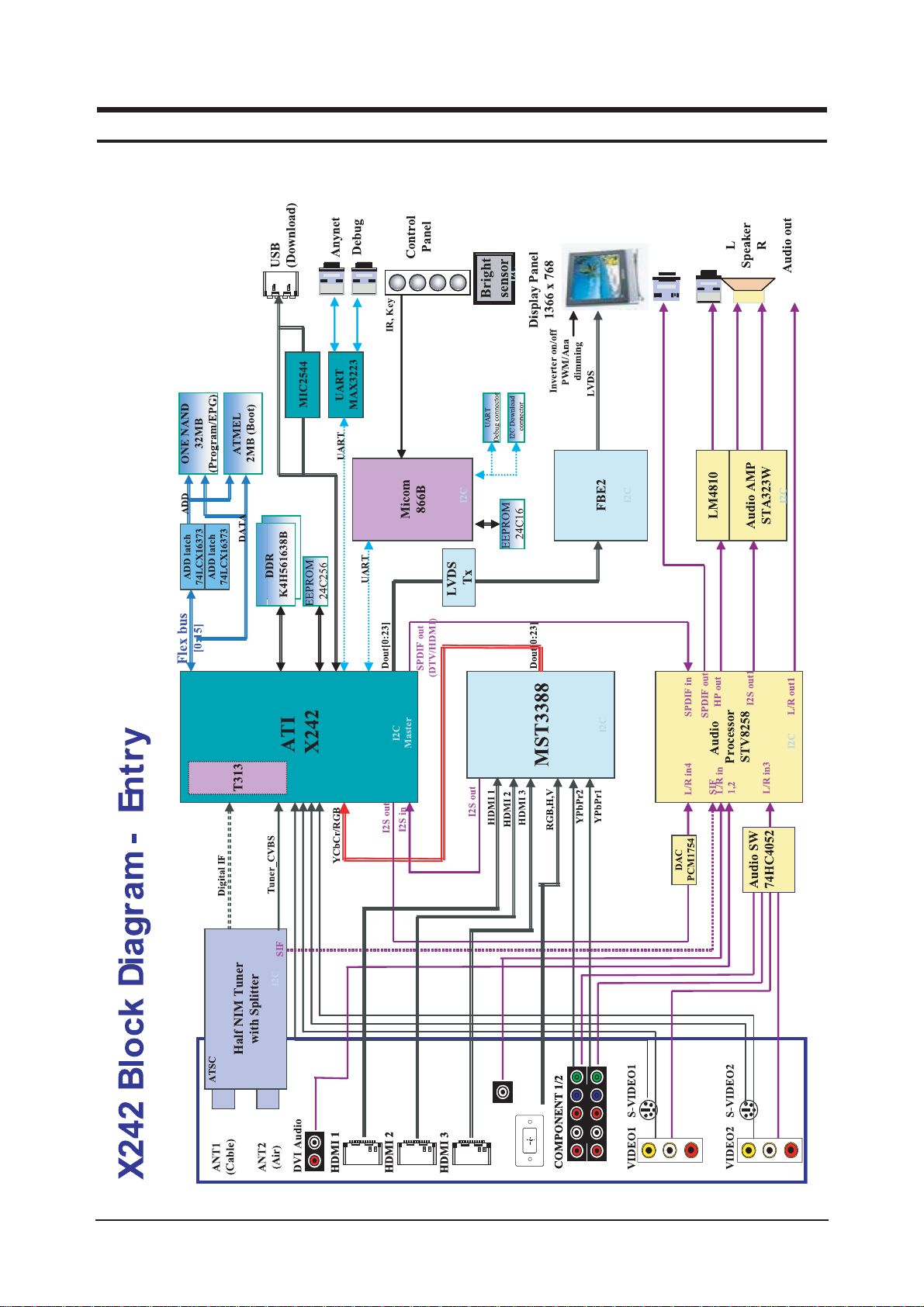
7 Block Diagram
- This Document can not be used without Samsung’s authorization

7 Block Diagrams
7-2
Memo
13 Circuit Descriptions
13-1
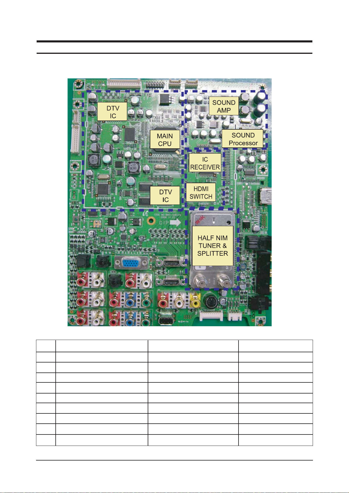
13 Circuit Descriptions
13-1 Block description
NO.
1
2
3
4
5
6
7
8
9
BLOCK
X242(IC202)
FBEX(IC1301)
SUB_MICOM(IC602)
SOUND AMP(IC1100)
SOUND PROCESSOR(IC1002)
TUNER(TU500)
DDR MEMORY(IC201)
IC-RECEIVER(IC1201)
HDMI SWITCH(IC1202)
DESCRIPTION
DTV DECODER
IMAGE BACKEND ENHANCER
CONTROL POWER,PANEL, etc.
SOUND AMP IC
SOUND MAIN PROCESSOR IC
HALF-NIM-TUNER & SPLITTER
X242 DDR MEMORY
2ADC+1HDMI
3 TO 1 HDMI SWITCH
REMARK
215H4AALA11HG
NZ2YFKC
WT61P6S
NTP3000(H12363B)
MSP4450K E8
DTVS227CH281A
HYB18T512161BF-25
MST3388MK-LF-110
SIL9185CTU

13 Circuit Descriptions
13-2
Memo
11 Disassembly and Reassembly
11-1
11 Disassembly and Reassembly
This section of the service manual describes the disassembly and reassembly procedures for the TFT-LCD TV.
WARNING : This monitor contains electrostatically sensitive devices. Use caution when
handling these components.
11-1 Disassembly
Cautions : 1. Disconnect the monitor from the power source before disassembly.
2. Follow these directions carefully; never use metal instruments to pry apart the
cabinet.
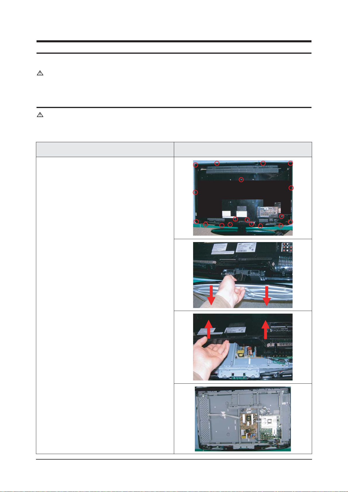
Description Description Picture
1. Place monitor face down on cushioned table.
Remove screws from the rear cover and stand.
Remove stand from the set.
Remove the rear cover.

11 Disassembly and Reassembly
11-2
설설 명 사사진 설명
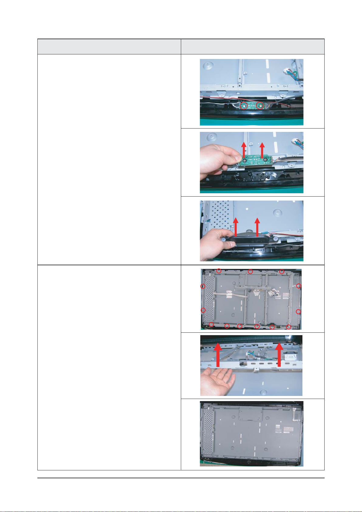
3. Remove screws of stand bracket.
Remove the bracket.
Description Description Picture
2. Disconnect cables from the mainboards and
SMPS.
Remove screws from the main board and
SMPS.
11 Disassembly and Reassembly
11-3
5. Remove screws and lift up the bracket.
Description Description Picture
4. Remove the screws of Assy P_function.
Remove Assy P_function.
Remove speakers.
11-2 Reassembly
Reassembly procedures are in the reverse order of disassembly procedures.
11 Disassembly and Reassembly
11-4
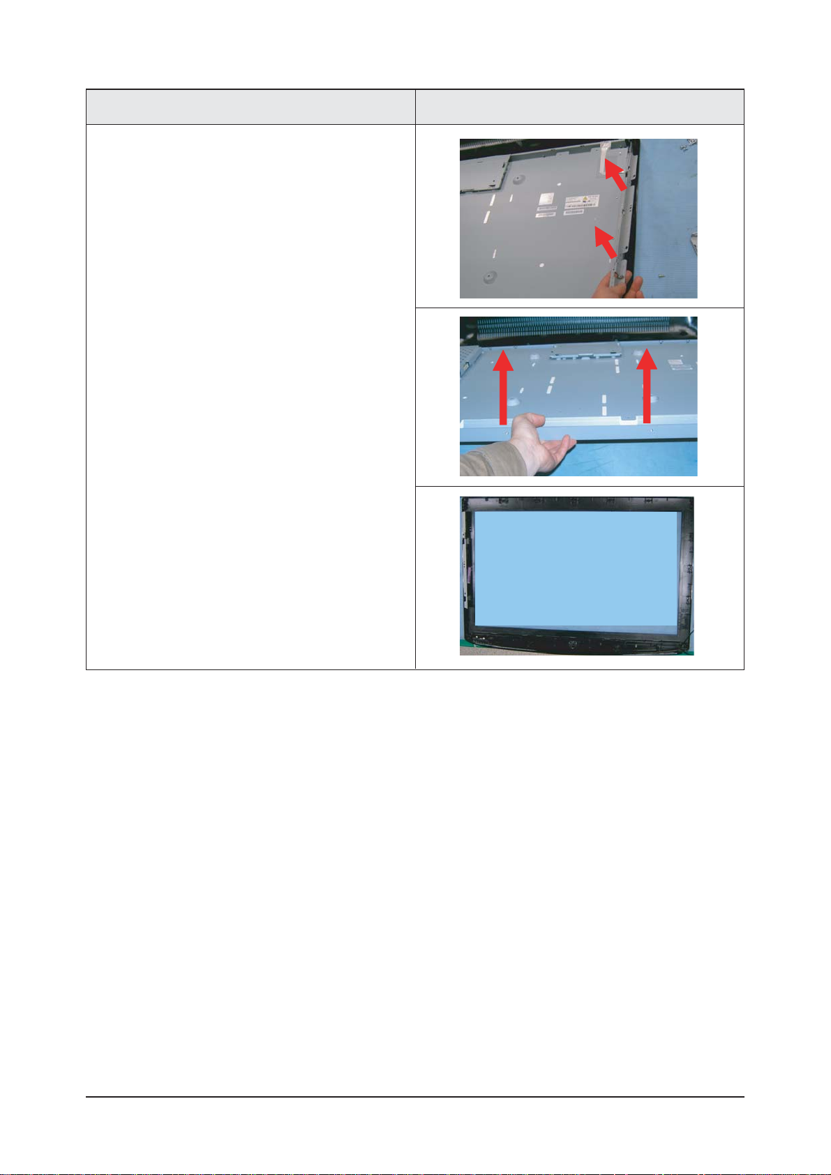
Description Description Picture
6. Lift up the bracket.
Lift up the LCD panel.
6 Electrical Parts List
6-1
Level Loc. No. Code No. Description & Specification Q'ty SA/SNA
LNT325HAX/XAA LN-T325HA,N36A/32R83-GBR,32,LCD-TV,UNITE
0.1 M0216 BN90-01149A ASSY STAND;32R81,M81,SWIVEL,-,-,-,- 1 S.N.A
..2 T0524 6902-000241 BAG PE;NITRON/HDPE,T0.5/T0.012,W600,L600 1 S.N.A
..2 M0027 BN96-04662A ASSY STAND P-BASE;32R81,M81,SWIVEL,-,ABS 1 S.A
...3 T0081 6002-001294 SCREW-TAPPING;BH,+,,M4,L16,ZPC(BLK) 4 S.A
...3 M0081 6003-001239 SCREW-TAPTITE;FH,+,-,B,M4,L10,ZPC(WHT),S 4 S.A
...3 BN61-02232A HOLDER-SWIVEL RING;32R71,ACETAL NATUAL,T 1 S.N.A
...3 BN61-02233A HOLDER-SWIVEL RING;32R71,ACETAL NATUAL,B 1 S.N.A
...3 BN61-02236A BRACKET-HINGE SWIVEL;BORDEAUX 32,SECC,T1 1 S.N.A
...3 BN61-02942A BRACKET-STAND BOTTOM;32,BORDEAUX PLUS,SE 1 S.N.A
...3 T0920 BN61-02943A GUIDE-STAND;32R81,ABS,V0,-,-,-,BK500,- 1 S.N.A
....4 BN61-02967A BRACKET-SUPPORT STAND;32 BORDEAUX PLUS,S 1 S.N.A
....4 T0514 BN61-03046A BRACKET-SUPPORT;32 BORDEAUX PLUS,SECC,2. 1 S.N.A
...3 CCM1 BN63-02183D COVER-SHEET;Rhcm,PE Vinyl,T0.05,680mm,20 0.4 S.N.A
...3 T0004 BN63-03102A COVER-STAND BASE;32R81,ABS+PMMA,-,-,-,HB 1 S.N.A
...3 T0132 BN73-00052A RUBBER FOOT;ARES 17,SILICON,DIA 17 * T1. 4 S.N.A
0.1 M0002 BN90-01153X ASSY COVER REAR;32R81,UO(CLUB),PC+ABS,V0 1 S.N.A
..2 T0081 6002-001294 SCREW-TAPPING;BH,+,,M4,L16,ZPC(BLK) 2 S.A
..2 T0081 6002-001294 SCREW-TAPPING;BH,+,,M4,L16,ZPC(BLK) 13 S.A
..2 M0013 BN96-04666N ASSY COVER P-REAR;32R81,UO(CLUB),PC+ABS, 1 S.A
...3 M0081 6003-001188 SCREW-TAPTITE;BH,+,-,B,M4,L10,ZPC(WHT),S 4 S.N.A
...3 T0101 BN61-03348A BRACKET-WALL;LCD TV 32",SECC T1.6 4 S.N.A
...3 CCM1 BN63-02183F COVER-SHEET;Rhcm,PE Vinyl,T0.05,900mm,20 0.7 S.N.A
...3 M0006 BN63-03101A COVER-REAR;32R81,UO,PC+ABS,-,-,-,V0,-,BK 1 S.N.A
...3 T0071 BN64-00554A INLAY-TERMINAL;07,COMMON,UO,PS SHEET,T0. 1 S.N.A
...3 T0064 BN65-00002A CLAMPER CORE;BORDEAUX,PP,V0,BLK 1 S.N.A
...3 T0067 BP60-00099A SPACER-SCREEN;Club-Bordeaux,EVA SPONGE,L 2 S.N.A
0.1 M0001 BN90-01317A ASSY COVER FRONT;32R83,UO(CLUB),-,PC+ABS 1 S.N.A
..2 T0175 BN96-04768B ASSY SPEAKER P;8ohm,4pin,10W,150/650,Bor 1 S.A
..2 T0003 BN96-05625A ASSY COVER P-FRONT;32R83,UO(CLUB),-,PC+A 1 S.A
...3 M0081 6003-001188 SCREW-TAPTITE;BH,+,-,B,M4,L10,ZPC(WHT),S 2 S.N.A
...3 M0081 6003-001188 SCREW-TAPTITE;BH,+,-,B,M4,L10,ZPC(WHT),S 2 S.N.A
...3 T0060 BN61-01655A SPRING ETC;STS-304 SUS,D8,L12,T0.5 1 S.N.A
...3 CCM1 BN63-02183F COVER-SHEET;Rhcm,PE Vinyl,T0.05,900mm,20 1.48 S.N.A
...3 M0112 BN63-03650A COVER-FRONT;32R83,UO,CLUB,PC+ABS,-,-,-,V 1 S.N.A
...3 T0059 BN64-00366A INDICATOR LED;ROME-I,PC,CLEAR,ALL MODEL 1 S.N.A
...3 T0023 BN64-00639A KNOB POWER;37 BORDEAUX PLUS,PC,-,-,-,-,V 1 S.N.A
...3 T0054 BN64-00640A KNOB-DECORATION;37 BORDEAUX PLUS,ABS,-,- 1 S.N.A
...3 T0022 BN64-00645A KNOB CONTROL;37 BORDEAUX PLUS,PC+ABS,-,- 1 S.N.A
...3 M0146 BN96-04884C ASSY BOARD P-POWER & IR;LNT4042HX/XAA,CT 1 S.A
...3 BN96-05667A ASSY HOLDER P-BOSS;32R81,CLUB,PC+ABS,V0, 1 S.N.A
....4 BN61-03261A BOSS-TAPE;Tulip,ACRYL,T1.1,W12mm,GRAY,TA 1.15 S.N.A
....4 BN61-03322A HOLDER-BOSS BOTTOM;32 BORDEAUX PLUS,ABS+ 1 S.N.A
....4 CCM1 BN63-02183F COVER-SHEET;Rhcm,PE Vinyl,T0.05,900mm,20 0.3 S.N.A
...3 BN63-01151A FELT-NON WOVEN;MM17NS,T0.5,393,10,BLACK 2 S.N.A
...3 T0069 BP60-00015D SPACER-FELT;617W,FELT,L760,T0.5,W10 2 S.N.A
...3 M0279 BN63-00867A FELT;AS17UO,FELT,0.5,10,68 1 S.N.A
...3 M0145 BN96-05677B ASSY BOARD P-FUNCTION;LNT375HAX,CT5000-5 1 S.N.A
0.1 M0017 BN91-01550E ASSY CHASSIS;LNT325HX/XAA.AMLCD 1 S.N.A
..2 M0014 BN94-01293F ASSY PCB MAIN-AMLCD;LNT325HAX/*VE 1 S.A
...3 T0245 0202-001492 SOLDER-WIRE FLUX;HSE-02 LFM48 SR-34 S,-, 0.25 S.N.A
...3 JA900S 3701-001388 CONNECTOR-HDMI;20P,Phosphor Bronze,ANGLE 1 S.A
...3 JA700 3701-001400 CONNECTOR-DSUB;15P,3R,FEMALE,STRAIGHT,Ni 1 S.A
...3 CN906 3707-001081 CONNECTOR-OPTICAL;STRAIGHT,SPDIF 1 S.A
...3 CN330 3711-000058 HEADER-BOARD TO CABLE;BOX,4P,1R,2.5MM,AN 1 S.A
...3 CN330 3711-004484 HEADER-BOARD TO CABLE;BOX,5P,1R,2mm,STRA 1 S.A
...3 CN330 3711-004531 HEADER-BOARD TO CABLE;BOX,10P,1R,2mm,ANG 1 S.A
...3 CN330 3711-005606 HEADER-BOARD TO CABLE;BOX,30P,2R,2mm,STR 1 S.A
...3 CN330 3711-005842 HEADER-BOARD TO CABLE;BOX,24P,2R,2MM,STR 1 S.A
...3 JA330 3722-000143 JACK-PHONE;1P(VER),AG,BLK,ANGLE 1 S.A
6 Electrical Parts List
-You can search for updated part codes through ITSELF web site.
URL : http://itself.sec.samsung.co.kr/
6-1 LNT325HAX Par ts List
6 Electrical Parts List
6-2
Level Loc. No. Code No. Description & Specification Q'ty S.A/S.N.A
...3 JA330 3722-001061 JACK-PHONE;1P,3.6PI,AG,BLK,N 1 S.A
...3 JA330 3722-001061 JACK-PHONE;1P,3.6PI,AG,BLK,N 1 S.A
...3 JA332 3722-001163 JACK-VHS;4P,AU,BLK,ANGLE 1 S.A
...3 JA332 3722-001734 JACK-VHS;4P,SN,BLK,STRAIGHT 1 S.A
...3 JA333 3722-002360 JACK-PIN;3P,AU,GRN/BLU/RED,STRAIGHT 1 S.A
...3 JA333 3722-002360 JACK-PIN;3P,AU,GRN/BLU/RED,STRAIGHT 1 S.A
...3 JA333 3722-002362 JACK-PIN;2P,Sn,WHT/RED,STRAIGHT 1 S.A
...3 JA333 3722-002362 JACK-PIN;2P,Sn,WHT/RED,STRAIGHT 1 S.A
...3 JA333 3722-002362 JACK-PIN;2P,Sn,WHT/RED,STRAIGHT 1 S.A
...3 JA333 3722-002362 JACK-PIN;2P,Sn,WHT/RED,STRAIGHT 1 S.A
...3 JA333 3722-002363 JACK-PIN;3P,Sn,YEL/WHT/RED,STRAIGHT 1 S.A
...3 CN700 3722-002516 JACK-USB;4P/1C,AU30U,BLK,STRAIGHT,A TYPE 1 S.A
...3 JA333 3722-002543 JACK-PIN;3P,Sn,RED/WHT/YEL,ANGLE 1 S.A
...3 CIS3 BN40-00097A TUNER;DTVS227CH281A,DTVS227CH281A,ATSC/N 1 S.A
...3 T0603 BN63-03210A SHIELD-PCB MAIN;BORDEAUX PLUS,SPTE,T0.3, 1 S.N.A
...3 CCMM1 BN73-00024D SILICON/RUBBER;BORDEAUX,SILICON,28x28XT6 1 S.N.A
...3 T0174 BN97-01586F ASSY SMD;LNT325HAX/* 1 S.N.A
....4 SUB05 0202-001477 SOLDER-CREAM;LST309-M,-,D20~45§-,96.5Sn/ 3.861 S.N.A
....4 D728 0401-000132 DIODE-SWITCHING;BAV99,70V,50mA,SOT-23,TP 1 S.A
....4 D729 0401-000132 DIODE-SWITCHING;BAV99,70V,50mA,SOT-23,TP 1 S.A
....4 D100 0401-000133 DIODE-SWITCHING;RLS4148,75V,150mA,LL-34, 1 S.A
....4 D1000 0401-000133 DIODE-SWITCHING;RLS4148,75V,150mA,LL-34, 1 S.A
....4 D101 0401-000133 DIODE-SWITCHING;RLS4148,75V,150mA,LL-34, 1 S.A
....4 D1102 0401-000133 DIODE-SWITCHING;RLS4148,75V,150mA,LL-34, 1 S.A
....4 D1103 0401-000133 DIODE-SWITCHING;RLS4148,75V,150mA,LL-34, 1 S.A
....4 D1400 0401-000133 DIODE-SWITCHING;RLS4148,75V,150mA,LL-34, 1 S.A
....4 D300 0401-000133 DIODE-SWITCHING;RLS4148,75V,150mA,LL-34, 1 S.A
....4 D1401 0401-001056 DIODE-SWITCHING;MMBD4148SE,100V,200mA,SO 1 S.A
....4 D1402 0401-001056 DIODE-SWITCHING;MMBD4148SE,100V,200mA,SO 1 S.A
....4 D1403 0401-001056 DIODE-SWITCHING;MMBD4148SE,100V,200mA,SO 1 S.A
....4 D1405 0401-001056 DIODE-SWITCHING;MMBD4148SE,100V,200mA,SO 1 S.A
....4 D1406 0401-001056 DIODE-SWITCHING;MMBD4148SE,100V,200mA,SO 1 S.A
....4 D500 0401-001056 DIODE-SWITCHING;MMBD4148SE,100V,200mA,SO 1 S.A
....4 D700 0401-001056 DIODE-SWITCHING;MMBD4148SE,100V,200mA,SO 1 S.A
....4 D701 0401-001056 DIODE-SWITCHING;MMBD4148SE,100V,200mA,SO 1 S.A
....4 D702 0401-001056 DIODE-SWITCHING;MMBD4148SE,100V,200mA,SO 1 S.A
....4 D703 0401-001056 DIODE-SWITCHING;MMBD4148SE,100V,200mA,SO 1 S.A
....4 D704 0401-001056 DIODE-SWITCHING;MMBD4148SE,100V,200mA,SO 1 S.A
....4 D711 0401-001056 DIODE-SWITCHING;MMBD4148SE,100V,200mA,SO 1 S.A
....4 D712 0401-001056 DIODE-SWITCHING;MMBD4148SE,100V,200mA,SO 1 S.A
....4 D713 0401-001056 DIODE-SWITCHING;MMBD4148SE,100V,200mA,SO 1 S.A
....4 D714 0401-001056 DIODE-SWITCHING;MMBD4148SE,100V,200mA,SO 1 S.A
....4 D715 0401-001056 DIODE-SWITCHING;MMBD4148SE,100V,200mA,SO 1 S.A
....4 D716 0401-001056 DIODE-SWITCHING;MMBD4148SE,100V,200mA,SO 1 S.A
....4 D717 0401-001056 DIODE-SWITCHING;MMBD4148SE,100V,200mA,SO 1 S.A
....4 D718 0401-001056 DIODE-SWITCHING;MMBD4148SE,100V,200mA,SO 1 S.A
....4 D724 0401-001056 DIODE-SWITCHING;MMBD4148SE,100V,200mA,SO 1 S.A
....4 D725 0401-001056 DIODE-SWITCHING;MMBD4148SE,100V,200mA,SO 1 S.A
....4 D730 0401-001056 DIODE-SWITCHING;MMBD4148SE,100V,200mA,SO 1 S.A
....4 D731 0401-001056 DIODE-SWITCHING;MMBD4148SE,100V,200mA,SO 1 S.A
....4 D732 0401-001056 DIODE-SWITCHING;MMBD4148SE,100V,200mA,SO 1 S.A
....4 D733 0401-001056 DIODE-SWITCHING;MMBD4148SE,100V,200mA,SO 1 S.A
....4 D734 0401-001056 DIODE-SWITCHING;MMBD4148SE,100V,200mA,SO 1 S.A
....4 D735 0401-001056 DIODE-SWITCHING;MMBD4148SE,100V,200mA,SO 1 S.A
....4 D736 0401-001056 DIODE-SWITCHING;MMBD4148SE,100V,200mA,SO 1 S.A
....4 D737 0401-001056 DIODE-SWITCHING;MMBD4148SE,100V,200mA,SO 1 S.A
....4 D902S 0401-001056 DIODE-SWITCHING;MMBD4148SE,100V,200mA,SO 1 S.A
....4 D903S 0401-001056 DIODE-SWITCHING;MMBD4148SE,100V,200mA,SO 1 S.A
....4 D905S 0401-001056 DIODE-SWITCHING;MMBD4148SE,100V,200mA,SO 1 S.A
....4 D906S 0401-001056 DIODE-SWITCHING;MMBD4148SE,100V,200mA,SO 1 S.A
....4 D907S 0401-001056 DIODE-SWITCHING;MMBD4148SE,100V,200mA,SO 1 S.A
....4 D908S 0401-001056 DIODE-SWITCHING;MMBD4148SE,100V,200mA,SO 1 S.A
....4 D909S 0401-001056 DIODE-SWITCHING;MMBD4148SE,100V,200mA,SO 1 S.A
....4 D910S 0401-001056 DIODE-SWITCHING;MMBD4148SE,100V,200mA,SO 1 S.A
....4 D911S 0401-001056 DIODE-SWITCHING;MMBD4148SE,100V,200mA,SO 1 S.A
....4 D912S 0401-001056 DIODE-SWITCHING;MMBD4148SE,100V,200mA,SO 1 S.A
....4 D1101 0401-001099 DIODE-SWITCHING;1N4148WS,75V,150mA,SOD-3 1 S.A
....4 D1104 0401-001099 DIODE-SWITCHING;1N4148WS,75V,150mA,SOD-3 1 S.A
....4 D1105 0401-001099 DIODE-SWITCHING;1N4148WS,75V,150mA,SOD-3 1 S.A
....4 D1106 0401-001099 DIODE-SWITCHING;1N4148WS,75V,150mA,SOD-3 1 S.A
....4 D1107 0401-001099 DIODE-SWITCHING;1N4148WS,75V,150mA,SOD-3 1 S.A
....4 D600D 0401-001099 DIODE-SWITCHING;1N4148WS,75V,150mA,SOD-3 1 S.A

6 Electrical Parts List
6-3
Level Loc. No. Code No. Description & Specification Q'ty S.A/S.N.A
....4 D602D 0401-001099 DIODE-SWITCHING;1N4148WS,75V,150mA,SOD-3 1 S.A
....4 D603 0401-001099 DIODE-SWITCHING;1N4148WS,75V,150mA,SOD-3 1 S.A
....4 D746 0401-001099 DIODE-SWITCHING;1N4148WS,75V,150mA,SOD-3 1 S.A
....4 D747 0401-001099 DIODE-SWITCHING;1N4148WS,75V,150mA,SOD-3 1 S.A
....4 D930 0401-001099 DIODE-SWITCHING;1N4148WS,75V,150mA,SOD-3 1 S.A
....4 D0254 0402-000553 DIODE-SCHOTTKY;SS24/B240,40V,2000mA,DO-2 1 S.A
....4 D102 0402-001098 DIODE-RECTIFIER;SK34,40V,3A,SMC,TP 1 S.A
....4 D601 0403-000620 DIODE-ZENER;RLZ5.6B,5.45-5.73V,500mW,LL- 1 S.A
....4 D609 0403-000620 DIODE-ZENER;RLZ5.6B,5.45-5.73V,500mW,LL- 1 S.A
....4 D719 0403-000620 DIODE-ZENER;RLZ5.6B,5.45-5.73V,500mW,LL- 1 S.A
....4 D739 0403-000620 DIODE-ZENER;RLZ5.6B,5.45-5.73V,500mW,LL- 1 S.A
....4 D913S 0403-000620 DIODE-ZENER;RLZ5.6B,5.45-5.73V,500mW,LL- 1 S.A
....4 D705 0403-001016 DIODE-ZENER;RLZ6.2B,5.96-6.27V,500mW,LL- 1 S.A
....4 D726 0403-001016 DIODE-ZENER;RLZ6.2B,5.96-6.27V,500mW,LL- 1 S.A
....4 D744 0403-001016 DIODE-ZENER;RLZ6.2B,5.96-6.27V,500mW,LL- 1 S.A
....4 D745 0403-001016 DIODE-ZENER;RLZ6.2B,5.96-6.27V,500mW,LL- 1 S.A
....4 D900S 0403-001016 DIODE-ZENER;RLZ6.2B,5.96-6.27V,500mW,LL- 1 S.A
....4 D901S 0403-001016 DIODE-ZENER;RLZ6.2B,5.96-6.27V,500mW,LL- 1 S.A
....4 D706 0403-001052 DIODE-ZENER;RD8.2MB,7.7-8.7V,200mW,SOT-2 1 S.A
....4 D707 0403-001052 DIODE-ZENER;RD8.2MB,7.7-8.7V,200mW,SOT-2 1 S.A
....4 D708 0403-001052 DIODE-ZENER;RD8.2MB,7.7-8.7V,200mW,SOT-2 1 S.A
....4 D709 0403-001052 DIODE-ZENER;RD8.2MB,7.7-8.7V,200mW,SOT-2 1 S.A
....4 D710 0403-001052 DIODE-ZENER;RD8.2MB,7.7-8.7V,200mW,SOT-2 1 S.A
....4 D720 0403-001052 DIODE-ZENER;RD8.2MB,7.7-8.7V,200mW,SOT-2 1 S.A
....4 D721 0403-001052 DIODE-ZENER;RD8.2MB,7.7-8.7V,200mW,SOT-2 1 S.A
....4 D722 0403-001052 DIODE-ZENER;RD8.2MB,7.7-8.7V,200mW,SOT-2 1 S.A
....4 D723 0403-001052 DIODE-ZENER;RD8.2MB,7.7-8.7V,200mW,SOT-2 1 S.A
....4 D727 0403-001052 DIODE-ZENER;RD8.2MB,7.7-8.7V,200mW,SOT-2 1 S.A
....4 D740 0403-001052 DIODE-ZENER;RD8.2MB,7.7-8.7V,200mW,SOT-2 1 S.A
....4 D741 0403-001052 DIODE-ZENER;RD8.2MB,7.7-8.7V,200mW,SOT-2 1 S.A
....4 D742 0403-001052 DIODE-ZENER;RD8.2MB,7.7-8.7V,200mW,SOT-2 1 S.A
....4 D743 0403-001052 DIODE-ZENER;RD8.2MB,7.7-8.7V,200mW,SOT-2 1 S.A
....4 D800 0403-001052 DIODE-ZENER;RD8.2MB,7.7-8.7V,200mW,SOT-2 1 S.A
....4 D801 0403-001052 DIODE-ZENER;RD8.2MB,7.7-8.7V,200mW,SOT-2 1 S.A
....4 D802 0403-001052 DIODE-ZENER;RD8.2MB,7.7-8.7V,200mW,SOT-2 1 S.A
....4 D803 0403-001052 DIODE-ZENER;RD8.2MB,7.7-8.7V,200mW,SOT-2 1 S.A
....4 D804 0403-001052 DIODE-ZENER;RD8.2MB,7.7-8.7V,200mW,SOT-2 1 S.A
....4 D805 0403-001052 DIODE-ZENER;RD8.2MB,7.7-8.7V,200mW,SOT-2 1 S.A
....4 D806 0403-001052 DIODE-ZENER;RD8.2MB,7.7-8.7V,200mW,SOT-2 1 S.A
....4 D807 0403-001052 DIODE-ZENER;RD8.2MB,7.7-8.7V,200mW,SOT-2 1 S.A
....4 D808 0403-001052 DIODE-ZENER;RD8.2MB,7.7-8.7V,200mW,SOT-2 1 S.A
....4 D809 0403-001052 DIODE-ZENER;RD8.2MB,7.7-8.7V,200mW,SOT-2 1 S.A
....4 D810 0403-001052 DIODE-ZENER;RD8.2MB,7.7-8.7V,200mW,SOT-2 1 S.A
....4 D811 0403-001052 DIODE-ZENER;RD8.2MB,7.7-8.7V,200mW,SOT-2 1 S.A
....4 D812 0403-001052 DIODE-ZENER;RD8.2MB,7.7-8.7V,200mW,SOT-2 1 S.A
....4 D813 0403-001052 DIODE-ZENER;RD8.2MB,7.7-8.7V,200mW,SOT-2 1 S.A
....4 D816 0403-001052 DIODE-ZENER;RD8.2MB,7.7-8.7V,200mW,SOT-2 1 S.A
....4 D817 0403-001052 DIODE-ZENER;RD8.2MB,7.7-8.7V,200mW,SOT-2 1 S.A
....4 D818 0403-001052 DIODE-ZENER;RD8.2MB,7.7-8.7V,200mW,SOT-2 1 S.A
....4 D819 0403-001052 DIODE-ZENER;RD8.2MB,7.7-8.7V,200mW,SOT-2 1 S.A
....4 D820 0403-001052 DIODE-ZENER;RD8.2MB,7.7-8.7V,200mW,SOT-2 1 S.A
....4 D821 0403-001052 DIODE-ZENER;RD8.2MB,7.7-8.7V,200mW,SOT-2 1 S.A
....4 D824 0403-001052 DIODE-ZENER;RD8.2MB,7.7-8.7V,200mW,SOT-2 1 S.A
....4 D825 0403-001052 DIODE-ZENER;RD8.2MB,7.7-8.7V,200mW,SOT-2 1 S.A
....4 D826 0403-001052 DIODE-ZENER;RD8.2MB,7.7-8.7V,200mW,SOT-2 1 S.A
....4 D827 0403-001052 DIODE-ZENER;RD8.2MB,7.7-8.7V,200mW,SOT-2 1 S.A
....4 D828 0403-001052 DIODE-ZENER;RD8.2MB,7.7-8.7V,200mW,SOT-2 1 S.A
....4 D829 0403-001052 DIODE-ZENER;RD8.2MB,7.7-8.7V,200mW,SOT-2 1 S.A
....4 D830 0403-001052 DIODE-ZENER;RD8.2MB,7.7-8.7V,200mW,SOT-2 1 S.A
....4 D831 0403-001052 DIODE-ZENER;RD8.2MB,7.7-8.7V,200mW,SOT-2 1 S.A
....4 D832 0403-001052 DIODE-ZENER;RD8.2MB,7.7-8.7V,200mW,SOT-2 1 S.A
....4 D833 0403-001052 DIODE-ZENER;RD8.2MB,7.7-8.7V,200mW,SOT-2 1 S.A
....4 D834 0403-001052 DIODE-ZENER;RD8.2MB,7.7-8.7V,200mW,SOT-2 1 S.A
....4 D835 0403-001052 DIODE-ZENER;RD8.2MB,7.7-8.7V,200mW,SOT-2 1 S.A
....4 D836 0403-001052 DIODE-ZENER;RD8.2MB,7.7-8.7V,200mW,SOT-2 1 S.A
....4 D837 0403-001052 DIODE-ZENER;RD8.2MB,7.7-8.7V,200mW,SOT-2 1 S.A
....4 D904S 0403-001052 DIODE-ZENER;RD8.2MB,7.7-8.7V,200mW,SOT-2 1 S.A
....4 D914S 0403-001052 DIODE-ZENER;RD8.2MB,7.7-8.7V,200mW,SOT-2 1 S.A
....4 D915S 0403-001052 DIODE-ZENER;RD8.2MB,7.7-8.7V,200mW,SOT-2 1 S.A
....4 D916S 0403-001052 DIODE-ZENER;RD8.2MB,7.7-8.7V,200mW,SOT-2 1 S.A
....4 D917S 0403-001052 DIODE-ZENER;RD8.2MB,7.7-8.7V,200mW,SOT-2 1 S.A
....4 D918S 0403-001052 DIODE-ZENER;RD8.2MB,7.7-8.7V,200mW,SOT-2 1 S.A

6 Electrical Parts List
6-4
Level Loc. No. Code No. Description & Specification Q'ty S.A/S.N.A
....4 D919S 0403-001052 DIODE-ZENER;RD8.2MB,7.7-8.7V,200mW,SOT-2 1 S.A
....4 D920S 0403-001052 DIODE-ZENER;RD8.2MB,7.7-8.7V,200mW,SOT-2 1 S.A
....4 D921S 0403-001052 DIODE-ZENER;RD8.2MB,7.7-8.7V,200mW,SOT-2 1 S.A
....4 D922S 0403-001052 DIODE-ZENER;RD8.2MB,7.7-8.7V,200mW,SOT-2 1 S.A
....4 D923S 0403-001052 DIODE-ZENER;RD8.2MB,7.7-8.7V,200mW,SOT-2 1 S.A
....4 D924S 0403-001052 DIODE-ZENER;RD8.2MB,7.7-8.7V,200mW,SOT-2 1 S.A
....4 D925S 0403-001052 DIODE-ZENER;RD8.2MB,7.7-8.7V,200mW,SOT-2 1 S.A
....4 D928S 0403-001052 DIODE-ZENER;RD8.2MB,7.7-8.7V,200mW,SOT-2 1 S.A
....4 D929S 0403-001052 DIODE-ZENER;RD8.2MB,7.7-8.7V,200mW,SOT-2 1 S.A
....4 D501 0403-001425 DIODE-ZENER;BZX84C33,31-35V,350mW,SOT-23 1 S.A
....4 D814 0406-001172 DIODE-TVS;CDS3C30GTH,48V,SMD 1 S.A
....4 D815 0406-001172 DIODE-TVS;CDS3C30GTH,48V,SMD 1 S.A
....4 D1100 0407-000123 DIODE-ARRAY;DAN202K,80V,100mA,CA2-3,SOT- 1 S.A
....4 D604 0407-000123 DIODE-ARRAY;DAN202K,80V,100mA,CA2-3,SOT- 1 S.A
....4 D605 0407-000123 DIODE-ARRAY;DAN202K,80V,100mA,CA2-3,SOT- 1 S.A
....4 D608 0407-000123 DIODE-ARRAY;DAN202K,80V,100mA,CA2-3,SOT- 1 S.A
....4 Q1000 0501-000280 TR-SMALL SIGNAL;KSA1182,PNP,150MW,SOT-23 1 S.A
....4 Q1102 0501-000280 TR-SMALL SIGNAL;KSA1182,PNP,150MW,SOT-23 1 S.A
....4 Q1106 0501-000280 TR-SMALL SIGNAL;KSA1182,PNP,150MW,SOT-23 1 S.A
....4 Q100 0501-000342 TR-SMALL SIGNAL;KSC1623-Y,NPN,200mW,SOT- 1 S.A
....4 Q101 0501-000342 TR-SMALL SIGNAL;KSC1623-Y,NPN,200mW,SOT- 1 S.A
....4 Q1100 0501-000342 TR-SMALL SIGNAL;KSC1623-Y,NPN,200mW,SOT- 1 S.A
....4 Q1103 0501-000342 TR-SMALL SIGNAL;KSC1623-Y,NPN,200mW,SOT- 1 S.A
....4 Q1104 0501-000342 TR-SMALL SIGNAL;KSC1623-Y,NPN,200mW,SOT- 1 S.A
....4 Q1105 0501-000342 TR-SMALL SIGNAL;KSC1623-Y,NPN,200mW,SOT- 1 S.A
....4 Q1300L 0501-000342 TR-SMALL SIGNAL;KSC1623-Y,NPN,200mW,SOT- 1 S.A
....4 Q1400 0501-000342 TR-SMALL SIGNAL;KSC1623-Y,NPN,200mW,SOT- 1 S.A
....4 Q500 0501-000342 TR-SMALL SIGNAL;KSC1623-Y,NPN,200mW,SOT- 1 S.A
....4 Q602 0501-000342 TR-SMALL SIGNAL;KSC1623-Y,NPN,200mW,SOT- 1 S.A
....4 Q409 0505-000110 FET-SILICON;2N7002,N,60V,115mA,7.5ohm,0. 1 S.A
....4 Q409 0505-000110 FET-SILICON;2N7002,N,60V,115mA,7.5ohm,0. 1 S.A
....4 Q409 0505-000110 FET-SILICON;2N7002,N,60V,115mA,7.5ohm,0. 1 S.A
....4 Q409 0505-000110 FET-SILICON;2N7002,N,60V,115mA,7.5ohm,0. 1 S.A
....4 Q409 0505-000275 FET-SILICON;SI4435DY,P,-30V,+-8.0A,0.014 1 S.A
....4 IC104 0801-002270 IC-CMOS LOGIC;74LCX16373,LATCH,TSSOP,48P 1 S.A
....4 IC104 0801-002270 IC-CMOS LOGIC;74LCX16373,LATCH,TSSOP,48P 1 S.A
....4 IC306 0904-001838 IC-BUS SWITCH;PCA9546APW,TSSOP,16P,5.1x4 1 S.A
....4 IC307 0904-001838 IC-BUS SWITCH;PCA9546APW,TSSOP,16P,5.1x4 1 S.A
....4 IC1001 1001-000164 IC-ANALOG MULTIPLEX;74HC4052,CMOS,SOP,16 1 S.A
....4 IC603 1001-001109 IC-ANALOG SWITCH;FST3125M,BUS SWITCH & C 1 S.A
....4 IC801 1001-001155 IC-ANALOG MULTIPLEX;NC7SB3157P6X,CMOS,SC 1 S.A
....4 IC106 1001-001440 IC-VIDEO SWITCH;SiI9185CTU,QFP,80P,3.3V, 1 S.A
....4 IC800 1006-001266 IC-LINE TRANSCEIVER;SP3232EEY,TSSOP,16P, 1 S.A
....4 IC112 1103-000129 IC-EEPROM;24C02,2Kbit,256x8Bit,SOP,8P,5x 1 S.A
....4 IC112 1103-000129 IC-EEPROM;24C02,2Kbit,256x8Bit,SOP,8P,5x 1 S.A
....4 IC112 1103-000129 IC-EEPROM;24C02,2Kbit,256x8Bit,SOP,8P,5x 1 S.A
....4 IC112 1103-000129 IC-EEPROM;24C02,2Kbit,256x8Bit,SOP,8P,5x 1 S.A
....4 IC112 1103-000129 IC-EEPROM;24C02,2Kbit,256x8Bit,SOP,8P,5x 1 S.A
....4 IC112 1103-001385 IC-EEPROM;24C256,256Kbit,32Kx8,SOP,8P,5x 1 S.A
....4 IC113 1105-001780 IC-DRAM;HYB18T512161BF,DDR2,512Mbit,32Mx 1 S.A
....4 DU410 1201-000166 IC-OP AMP;LM358,SOP,ST,8P,150MIL,DUAL,10 1 S.A
....4 T0085 1201-002136 IC-AUDIO AMP;LM4810,MSOP,8P,3x3mm,DUAL,- 1 S.A
....4 T0124 1201-002430 IC-POWER AMP;NTP-3000,QFN,56P,8x8mm,DUAL 1 S.A
....4 T0087 1203-001815 IC-POSI.FIXED REG.;78M09,TO-252,3P,-,PLA 1 S.A
....4 T0087 1203-002074 IC-POSI.FIXED REG.;MIC39150,TO-263,3P,-, 1 S.A
....4 T0087 1203-002835 IC-POSI.FIXED REG.;KIA7805AF,DPAK,3P,6.6 1 S.A
....4 T0087 1203-002842 IC-POSI.FIXED REG.;AP1117D-33A,TO-252,3P 1 S.A
....4 T0170 1203-003059 IC-SWITCH VOL. REG.;MP1583,SOIC,8P,4.9x3 1 S.A
....4 T0087 1203-003121 IC-POSI.FIXED REG.;FAN1112,SOT-223,3P,6. 1 S.A
....4 IC062 1203-003183 IC-MULTI REG.;SI-3002KWM-TL,DPAK,5P,6.6X 1 S.A
....4 T0087 1203-003696 IC-POSI.FIXED REG.;NCP1117DT18T5G,DPAK,3 1 S.A
....4 T0087 1203-003703 IC-POSI.FIXED REG.;AP1117E-18A,SOT-223,3 1 S.A
....4 IC102 1203-004268 IC-DC/DC CONVERTER;SC4521SETRT,SOIC,8P,4 1 S.N.A
....4 IC600 1203-004364 IC-VOL. DETECTOR;RT9818C-42PV,SOT-23,3P, 1 S.A
....4 IC601 1203-004364 IC-VOL. DETECTOR;RT9818C-42PV,SOT-23,3P, 1 S.A
....4 IC202 1204-002648 IC-DECODER;215H4AALA11HG,BGA,444P,27x27m 1 S.A
....4 IC1002 1204-002708 IC-AUDIO PROCESSOR;MSP4450K-VK-E8-500,PM 1 S.A
....4 IC118 1204-002729 IC-VIDEO PROCESS;S4LF119X01,PBGA,208P,17 1 S.A
....4 IC1201 1205-003149 IC-RECEIVER;MST3388MK-LF-110,PQFP,128P,2 1 S.A
....4 R1244 2007-000042 R-CHIP;499ohm,1%,1/10W,TP,1608 1 S.A
....4 R286 2007-000043 R-CHIP;1Kohm,1%,1/10W,TP,1608 1 S.A
....4 R295 2007-000043 R-CHIP;1Kohm,1%,1/10W,TP,1608 1 S.A
6 Electrical Parts List
6-5
Level Loc. No. Code No. Description & Specification Q'ty S.A/S.N.A
....4 R296 2007-000043 R-CHIP;1Kohm,1%,1/10W,TP,1608 1 S.A
....4 R297 2007-000043 R-CHIP;1Kohm,1%,1/10W,TP,1608 1 S.A
....4 R298 2007-000043 R-CHIP;1Kohm,1%,1/10W,TP,1608 1 S.A
....4 R299 2007-000043 R-CHIP;1Kohm,1%,1/10W,TP,1608 1 S.A
....4 R1236 2007-000052 R-CHIP;10Kohm,1%,1/10W,TP,1608 1 S.A
....4 R1319 2007-000052 R-CHIP;10Kohm,1%,1/10W,TP,1608 1 S.A
....4 R602 2007-000052 R-CHIP;10Kohm,1%,1/10W,TP,1608 1 S.A
....4 R500 2007-000060 R-CHIP;100Kohm,1%,1/10W,TP,1608 1 S.A
....4 R504 2007-000060 R-CHIP;100Kohm,1%,1/10W,TP,1608 1 S.A
....4 R1117 2007-000070 R-CHIP;0ohm,5%,1/10W,TP,1608 1 S.A
....4 R1238 2007-000070 R-CHIP;0ohm,5%,1/10W,TP,1608 1 S.A
....4 R1240 2007-000070 R-CHIP;0ohm,5%,1/10W,TP,1608 1 S.A
....4 R1243 2007-000070 R-CHIP;0ohm,5%,1/10W,TP,1608 1 S.A
....4 R1245 2007-000070 R-CHIP;0ohm,5%,1/10W,TP,1608 1 S.A
....4 R1250 2007-000070 R-CHIP;0ohm,5%,1/10W,TP,1608 1 S.A
....4 R1251 2007-000070 R-CHIP;0ohm,5%,1/10W,TP,1608 1 S.A
....4 R1321 2007-000070 R-CHIP;0ohm,5%,1/10W,TP,1608 1 S.A
....4 R1322 2007-000070 R-CHIP;0ohm,5%,1/10W,TP,1608 1 S.A
....4 R1323 2007-000070 R-CHIP;0ohm,5%,1/10W,TP,1608 1 S.A
....4 R1325 2007-000070 R-CHIP;0ohm,5%,1/10W,TP,1608 1 S.A
....4 R1327 2007-000070 R-CHIP;0ohm,5%,1/10W,TP,1608 1 S.A
....4 R1328 2007-000070 R-CHIP;0ohm,5%,1/10W,TP,1608 1 S.A
....4 R1329 2007-000070 R-CHIP;0ohm,5%,1/10W,TP,1608 1 S.A
....4 R1330 2007-000070 R-CHIP;0ohm,5%,1/10W,TP,1608 1 S.A
....4 R1332 2007-000070 R-CHIP;0ohm,5%,1/10W,TP,1608 1 S.A
....4 R1333 2007-000070 R-CHIP;0ohm,5%,1/10W,TP,1608 1 S.A
....4 R1334 2007-000070 R-CHIP;0ohm,5%,1/10W,TP,1608 1 S.A
....4 R1335 2007-000070 R-CHIP;0ohm,5%,1/10W,TP,1608 1 S.A
....4 R1336 2007-000070 R-CHIP;0ohm,5%,1/10W,TP,1608 1 S.A
....4 R1337 2007-000070 R-CHIP;0ohm,5%,1/10W,TP,1608 1 S.A
....4 R1338 2007-000070 R-CHIP;0ohm,5%,1/10W,TP,1608 1 S.A
....4 R1339 2007-000070 R-CHIP;0ohm,5%,1/10W,TP,1608 1 S.A
....4 R1340 2007-000070 R-CHIP;0ohm,5%,1/10W,TP,1608 1 S.A
....4 R1341 2007-000070 R-CHIP;0ohm,5%,1/10W,TP,1608 1 S.A
....4 R1342 2007-000070 R-CHIP;0ohm,5%,1/10W,TP,1608 1 S.A
....4 R1343 2007-000070 R-CHIP;0ohm,5%,1/10W,TP,1608 1 S.A
....4 R1344 2007-000070 R-CHIP;0ohm,5%,1/10W,TP,1608 1 S.A
....4 R1345 2007-000070 R-CHIP;0ohm,5%,1/10W,TP,1608 1 S.A
....4 R1346 2007-000070 R-CHIP;0ohm,5%,1/10W,TP,1608 1 S.A
....4 R1358L 2007-000070 R-CHIP;0ohm,5%,1/10W,TP,1608 1 S.A
....4 R1366L 2007-000070 R-CHIP;0ohm,5%,1/10W,TP,1608 1 S.A
....4 R1368L 2007-000070 R-CHIP;0ohm,5%,1/10W,TP,1608 1 S.A
....4 R1371 2007-000070 R-CHIP;0ohm,5%,1/10W,TP,1608 1 S.A
....4 R1372 2007-000070 R-CHIP;0ohm,5%,1/10W,TP,1608 1 S.A
....4 R1373 2007-000070 R-CHIP;0ohm,5%,1/10W,TP,1608 1 S.A
....4 R1374 2007-000070 R-CHIP;0ohm,5%,1/10W,TP,1608 1 S.A
....4 R1375 2007-000070 R-CHIP;0ohm,5%,1/10W,TP,1608 1 S.A
....4 R1376 2007-000070 R-CHIP;0ohm,5%,1/10W,TP,1608 1 S.A
....4 R1377 2007-000070 R-CHIP;0ohm,5%,1/10W,TP,1608 1 S.A
....4 R1378 2007-000070 R-CHIP;0ohm,5%,1/10W,TP,1608 1 S.A
....4 R200 2007-000070 R-CHIP;0ohm,5%,1/10W,TP,1608 1 S.A
....4 R201 2007-000070 R-CHIP;0ohm,5%,1/10W,TP,1608 1 S.A
....4 R210 2007-000070 R-CHIP;0ohm,5%,1/10W,TP,1608 1 S.A
....4 R224 2007-000070 R-CHIP;0ohm,5%,1/10W,TP,1608 1 S.A
....4 R230 2007-000070 R-CHIP;0ohm,5%,1/10W,TP,1608 1 S.A
....4 R231 2007-000070 R-CHIP;0ohm,5%,1/10W,TP,1608 1 S.A
....4 R256 2007-000070 R-CHIP;0ohm,5%,1/10W,TP,1608 1 S.A
....4 R262 2007-000070 R-CHIP;0ohm,5%,1/10W,TP,1608 1 S.A
....4 R266 2007-000070 R-CHIP;0ohm,5%,1/10W,TP,1608 1 S.A
....4 R269 2007-000070 R-CHIP;0ohm,5%,1/10W,TP,1608 1 S.A
....4 R278 2007-000070 R-CHIP;0ohm,5%,1/10W,TP,1608 1 S.A
....4 R281 2007-000070 R-CHIP;0ohm,5%,1/10W,TP,1608 1 S.A
....4 R287 2007-000070 R-CHIP;0ohm,5%,1/10W,TP,1608 1 S.A
....4 R303 2007-000070 R-CHIP;0ohm,5%,1/10W,TP,1608 1 S.A
....4 R319 2007-000070 R-CHIP;0ohm,5%,1/10W,TP,1608 1 S.A
....4 R322 2007-000070 R-CHIP;0ohm,5%,1/10W,TP,1608 1 S.A
....4 R329 2007-000070 R-CHIP;0ohm,5%,1/10W,TP,1608 1 S.A
....4 R349 2007-000070 R-CHIP;0ohm,5%,1/10W,TP,1608 1 S.A
....4 R600D 2007-000070 R-CHIP;0ohm,5%,1/10W,TP,1608 1 S.A
....4 R603D 2007-000070 R-CHIP;0ohm,5%,1/10W,TP,1608 1 S.A
....4 R665 2007-000070 R-CHIP;0ohm,5%,1/10W,TP,1608 1 S.A
....4 R667 2007-000070 R-CHIP;0ohm,5%,1/10W,TP,1608 1 S.A
 Loading...