

Page 1

LCD-TV
Chassis : N45C
Model : LN19A330J1D
Manual
SERVICE
TFT-LCD TV Contents
1. Precautions
2. Product specications
Disassembly and Reassembly
3.
Troubleshooting
4.
Exploded View & Part List
5.
Wiring Diagram
6.
Schematic Diagram
7.
LN19A330J1D
Refer to the service manual in the GSPN (see the rear cover) for the more information.
Page 2

Contents
1. Precautions ..............................................................................................................1-1
1-1. Safety Precautions .........................................................................................................1-1
1-2. Servicing Precautions .....................................................................................................1-2
1-3. Electrostatically Sensitive Devices (ESD) Precautions ..................................................1-2
1-4. Installation Precautions ..................................................................................................1-3
2. Product specications ............................................................................................2-1
2-1. Feature & Specications .................................................................................................2-1
2-3. Spec Comparison to the Old Models ..............................................................................2-4
2-4. Accessories ....................................................................................................................2-5
3. Disassembly and Reassemble ............................................................................... 3-1
3-1. Disassembly ...................................................................................................................3-1
4. Troubleshooting ......................................................................................................4-1
4-1. Troubleshooting ..............................................................................................................4-1
4-2. Alignments and Adjustments ...................................................................................
4-3. Factory Mode Adjustments ....................................................................................
4-4. White Balance - Calibration ..........................................................................................4-28
4-5. White Ratio (Balance) Adjustment ................................................................................4-30
4-6. Servicing Information ....................................................................................................4-31
.....4-19
.......4-20
5. Exploded View & Part List ...................................................................................... 5-1
5-1. LN19A330J1D Exploded View ........................................................................................5-1
5-3. LN19A330J1D Parts List ................................................................................................5-3
6. Wiring Diagram ........................................................................................................6-1
6-1. Wiring Diagram ...............................................................................................................6-1
6-2. Cables ............................................................................................................................6-3
7. Schematic Diagram ................................................................................................. 7-1
7-1. MSD2248AL Block Diagram ...........................................................................................7-1
7-2. Slim Half Tuner Block Diagram .......................................................................................7-2
7-3. Internal Block Diagram of Scaler(MSD2248AL) .............................................................7-3
7-2. Schematic Diagrams ......................................................................................................7-4
Page 3

GSPN (Global Service Partner Network)
Area Web Site
North America http://service.samsungportal.com
America http://latin.samsungportal.com
Latin
CIS http://cis.samsungportal.com
Europe http://europe.samsungportal.com
China http://china.samsungportal.com
Asia http://asia.samsungportal.com
Mideast
This
Any unauthorized use of Manual can be punished under applicable
International and/or domestic law.
& Africa http://mea.samsungportal.com
Service Manual is a property of Samsung Electronics Co.,Ltd.
© 2008 Samsung Electronics Co.,Ltd.
All rights reserved.
Printed in Korea
P/N: BN82-00364A-00
Page 4

1. Precautions
1. Precautions
1-1. Safety Precautions
Follow these safety, servicing and ESD precautions to prevent damage and to protect against potential hazards such as
electrical shock.
1-1-1. Warnings
For continued safety, do not attempt to modify the circuit board.
1.
Disconnect the AC power and DC power jack before servicing.
2.
1-1-2. Servicing the LCD TV
When servicing the LCD TV, Disconnect the AC line cord from the AC outlet.
1.
It is essential that service technicians have an accurate voltage meter available at all times. Check the calibration of
2.
this meter periodically.
1-1-3. Fire and Shock Hazard
Before returning the LCD TV to the user, perform the following safety checks:
Inspect each lead dress to make certain that the leads are not pinched or that hardware is not lodged between the
1.
chassis and other metal parts in the LCD TV.
Inspect all protective devices such as nonmetallic control knobs, insulating materials, cabinet backs, adjustment and
2.
compartment covers or shields, isolation resistorcapacitor networks, mechanical insulators, etc.
Leakage Current Hot Check (Figure 1-1):
3.
WARNING : Do not use an isolation transformer during this test.
Use a leakage current tester or a metering system that complies with American National Standards Institute (ANSI
C101.1, Leakage Current for Appliances), and Underwriters Laboratories (UL Publication UL1410, 59.7).
(READING SHOULD)
NOT BE ABOVE 0.5mA
DEVICE
UNDER
TEST
TEST ALL
EXPOSED METAL
SURFACES
2-WIRE CORD
*ALSO TEST WITH
PLUG REVERSED
(USING AC ADAPTER
PLUG AS REQUIRED)
With the unit completely reassembled, plug the AC line cord directly into a 120V AC outlet. With the unit’s AC switch
4.
LEAKAGE
CURRENT
TESTER
EARTH
GROUND
Figure 1-1. Leakage Current Test Circuit
rst in the ON position and then OFF, measure the current between a known earth ground (metal water pipe, conduit,
etc.) and all exposed metal parts, including: metal cabinets, screwheads and control shafts.
The current measured should not exceed 0.5 milliamp.
Reverse the power-plug prongs in the AC outlet and repeat the test.
1-1-4. Product Safety Notices
Some electrical and mechanical parts have special safetyrelated characteristics which are often not evident from visual
inspection. The protection they give may not be obtained by replacing them with components rated for higher voltage,
wattage, etc. Parts that have special safety characteristics are identied by on schematics and parts lists. A substitute
replacement that does not have the same safety characteristics as the recommended replacement part might create
shock, re and/or other hazards. Product safety is under review continuously and new instructions are issued whenever
appropriate.
1-1
Page 5

1-2
1. Precautions
1-2. Servicing Precautions
WARNING: An electrolytic capacitor installed with the wrong polarity might explode.
Caution: Before servicing units covered by this service manual, read and follow the Safety Precautions section of
this manual.
Note: If unforeseen circumstances create conict between the following servicing precautions and any of the
safety precautions, always follow the safety precautions.
1-2-1 General Servicing Precautions
Always unplug the unit’s AC power cord from the AC power source and disconnect the DC Power Jack before
1.
attempting to:
(a) remove or reinstall any component or assembly, (b) disconnect PCB plugs or connectors, (c) connect a test
component in parallel with an electrolytic capacitor.
Some components are raised above the printed circuit board for safety. An insulation tube or tape is sometimes
2.
used. The internal wiring is sometimes clamped to prevent contact with thermally hot components. Reinstall all such
elements to their original position.
After servicing, always check that the screws, components and wiring have been correctly reinstalled. Make sure that
3.
the area around the serviced part has not been damaged.
Check the insulation between the blades of the AC plug and accessible conductive parts (examples: metal panels,
4.
input terminals and earphone jacks).
Insulation Checking Procedure: Disconnect the power cord from the AC source and turn the power switch ON.
5.
Connect an insulation resistance meter (500 V) to theblades of the AC plug.
The insulation resistance between each blade of the AC plug and accessible conductive parts (see above) should be
greater than 1 megohm.
Always connect a test instrument’s ground lead to the instrument chassis ground before connecting the positive lead;
6.
always remove the instrument’s ground lead last.
1-3. Electrostatically Sensitive Devices (ESD) Precautions
Some semiconductor (solid state) devices can be easily damaged by static electricity. Such components are commonly
called Electrostatically Sensitive Devices (ESD). Examples of typical ESD are integrated circuits and some eld-effect
transistors. The following techniques will reduce the incidence of component damage caused by static electricity.
Immediately before handling any semiconductor components or assemblies, drain the electrostatic charge from your
1.
body by touching a known earth ground. Alternatively, wear a discharging wrist-strap device. To avoid a shock hazard,
be sure to remove the wrist strap before applying power to the LCD TV.
After removing an ESD-equipped assembly, place it on a conductive surface such as aluminum foil to prevent
2.
accumulation of an electrostatic charge.
Do not use freon-propelled chemicals. These can generate electrical charges sufcient to damage ESDs.
3.
Use only a grounded-tip soldering iron to solder or desolder ESDs.
4.
Use only an anti-static solder removal device. Some solder removal devices not classied as “anti-static” can generate
5.
electrical charges sufcient to damage ESDs.
Do not remove a replacement ESD from its protective package until you are ready to install it. Most replacement ESDs
6.
are packaged with leads that are electrically shorted together by conductive foam, aluminum foil or other conductive
materials.
Immediately before removing the protective material from the leads of a replacement ESD, touch the protective
7.
material to the chassis or circuit assembly into which the device will be installed.
Caution: Be sure no power is applied to the chassis or circuit and observe all other safety precautions.
Minimize body motions when handling unpackaged replacement ESDs. Motions such as brushing clothes together,
8.
or lifting your foot from a carpeted oor can generate enough static electricity to damage an ESD.
Page 6

1. Precautions
1-4. Installation Precautions
For safety reasons, more than two people are required for carrying the product.
1.
Keep the power cord away from any heat emitting devices, as a melted covering may cause re or electric shock.
2.
Do not place the product in areas with poor ventilation such as a bookshelf or closet. The increased internal
3.
temperature may cause re.
Bend the external antenna cable when connecting it to the product. This is a measure to protect it from being exposed
4.
to moisture. Otherwise, it may cause a re or electric shock.
Make sure to turn the power off and unplug the power cord from the outlet before repositioning the product. Also check
5.
the antenna cable or the external connectors if they are fully unplugged. Damage to the cord may cause re or electric
shock.
Keep the antenna far away from any high-voltage cables and install it rmly. Contact with the highvoltage cable or the
6.
antenna falling over may cause re or electric shock.
When installing the product, leave enough space (10cm) between the product and the wall for ventilation purposes.
7.
A rise in temperature within the product may cause re.
1-3
Page 7

1. Precautions
Memo
1-4
Page 8

2. Product specications
2-1. Feature & Specications
Model LN19A330J1D
Feature
Digital-TV, RF, 1-HDMI, 1-Component, 1-A/V, 1-S-Video, D-SUB
�
Brightness : 300cd/m
�
Contrast Ratio : 1000:1
�
Response time : 5ms
�
Item Description
2
Specications
2. Product specications
LCD Panel TFT-LCD panel, RGB vertical stripe, TN mode, Normally white, 19-inch viewable,
Scanning Frequency Horizontal : 30 kHz ~ 80 kHz (Automatic)
Display Colors 16.7 million colors
Maximum resolution Horizontal : 1440 Pixels
Input Signal Analog 0.7 Vp-p ± 5% positive at 75Ω , internally terminated
Input Sync Signal H/V Separate, TTL, P. or N.
Maximum Pixel Clock rate 310MHz
Active Display
Horizontal/Vertical 16.07 x 10.05 inches(408.24(H) x 255.15(V)mm)
AC power voltage & Frequency AC 110V ~ 220V, 60 Hz
Power Consumption <245 W ( < 1W, stand by )
Dimensions
Set (W x D x H)
Weight (Set) 11.24 lbs (5.1kg)
TV System Tuning Frequency Synthesize (Refer to detailed Frequency Table)
0.2835(H) x 0.2835(W) x 3mm pixel pitch
Vertical : 56 Hz ~ 75 Hz (Automatic)
Vertical : 900 Pixels
18.78 x 7.09 x 15.24 inches (477.1 x 180.2 x 387 mm)_with stand
18.78 x 2.26 x 13.63 inches (477.1 x 57.5 x 346.1 mm)_without stand
System ATSC, NTSC5.38
Sound NTSC-M, AC-3 Digital
Environmental Considerations Operating Temperature : 50˚F ~ 104˚F (10˚C ~ 40˚C)
Operating Humidity : 10% ~ 80%, non-condensing
Storage temperature : -13˚F ~ 113˚F (-25˚C ~ 45˚C)
Storage Humidity : 5% ~ 95%, non-condensing
Environmental Considerations - MAX Internal speaker Out : Right => 10W, Left => 10W
- BASS Control Range : -8 dB ~ + 8dB
- TREBLE Control Range : -8 dB ~ +8 dB
- Headphone Out : 10 mW MAX
- Output Frequency : RF : 80 Hz ~ 15 kHz
A/V : 80 Hz ~ 20 kHz
Note: Anynet+
2-1
Page 9
2. Product specications
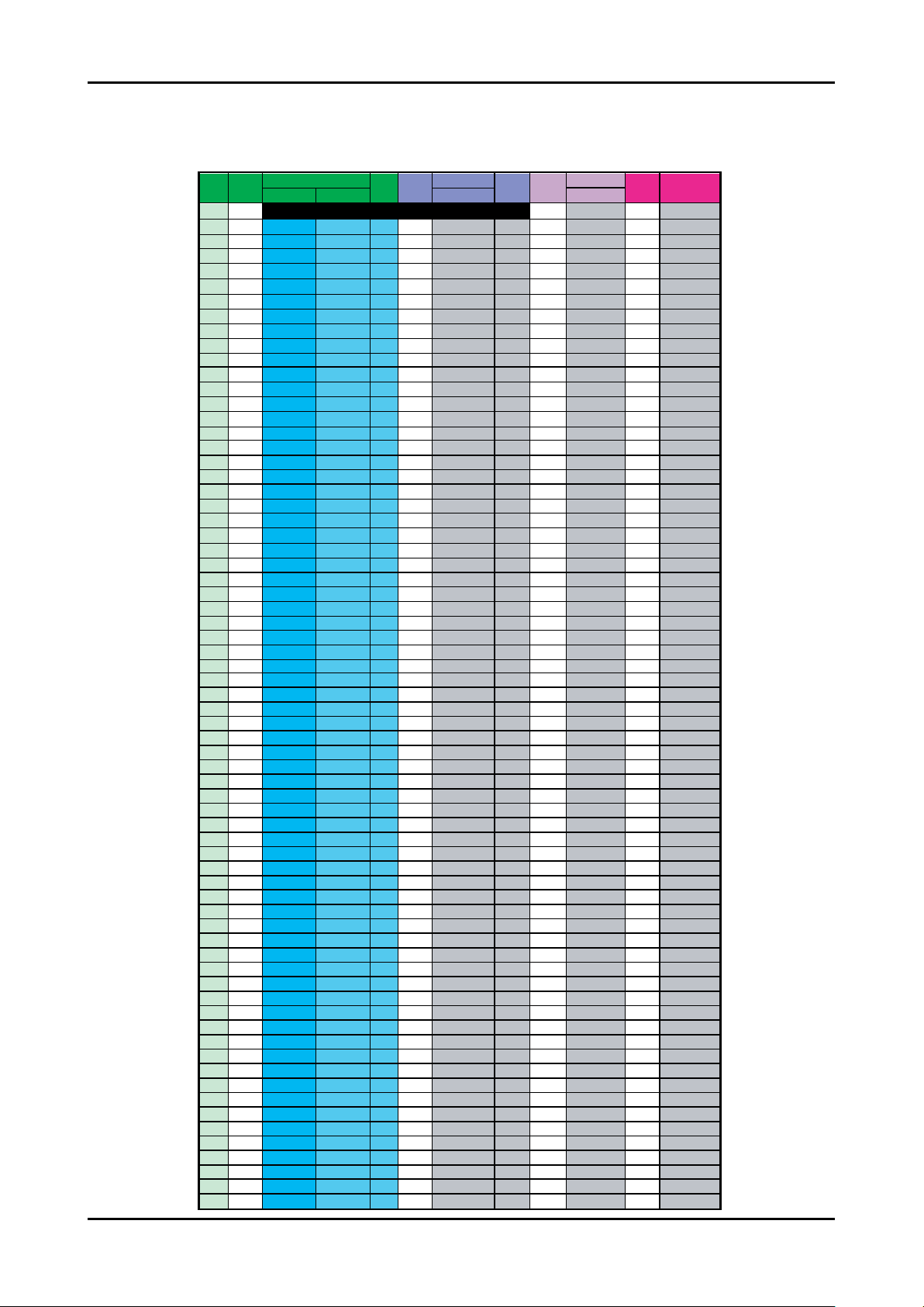
OSD CH NO AIR CH NO CH NO CH NO
Air-DTV Air-NTSC BAND Cable STD BAND Cable HRC Cable IRC
1 1 A-8 72. 00 A-8 73. 25
2 2 57 55. 25 V-L 2 55. 25 V-L 2 54. 00 2 55. 25
3 3 63 61.25 V-L 3 61.25 V-L 3 60.00 3 61.25
4 4 69 67.25 V-L 4 67.25 V-L 4 66.00 4 67.25
5 5 79 77. 25 V-L 5 77. 25 V-L A-7 78. 00 A-7 79. 25
6 6 85 83.25 V-L 6 83.25 V-L A-6 84.00 A-6 85.25
7 7 177 175. 25 V-H 7 175. 25 V-H 7 174. 00 7 175. 25
8 8 183 181.25 V-H 8 181.25 V-H 8 180.00 8 181.25
9 9 189 187.25 V-H 9 187.25 V-H 9 186.00 9 187.25
10 10 195 193.25 V-H 10 193.25 V-H 10 192.00 10 193.25
11 11 201 199.25 V-H 11 199.25 V-H 11 198.00 11 199.25
12 12 207 205.25 V-H 12 205.25 V-H 12 204.00 12 205.25
13 13 213 211.25 V-H 13 211.25 V-H 13 210.00 13 211.25
14 14 473 471. 25 UHF A 121. 25 MID A 120. 00 A 121. 25
15 15 479 477.25 UHF B 127.25 MID B 126.00 B 127.25
16 16 485 483.25 UHF C 133.25 MID C 132.00 C 133.25
17 17 491 489.25 UHF D 139.25 MID D 138.00 D 139.25
18 18 497 495.25 UHF E 145.25 MID E 144.00 E 145.25
19 19 503 501.25 UHF F 151.25 MID F 150.00 F 151.25
20 20 509 507.25 UHF G 157.25 MID G 156.00 G 157.25
21 21 515 513.25 UHF H 163.25 MID H 162.00 H 163.25
22 22 521 519.25 UHF I 169.25 MID I 168.00 I 169.25
23 23 527 525.25 UHF J 217. 25 SUPER J 216. 00 J 217. 25
24 24 533 531.25 UHF K 223.25 SUPER K 222.00 K 223.25
25 25 539 537.25 UHF L 229.25 SUPER L 228.00 L 229.25
26 26 545 543.25 UHF M 235.25 SUPER M 234.00 M 235.25
27 27 551 549.25 UHF N 241.25 SUPER N 240.00 N 241.25
28 28 557 555.25 UHF O 247.25 SUPER O 246.00 O 247.25
29 29 563 561.25 UHF P 253.25 SUPER P 252.00 P 253.25
30 30 569 567.25 UHF Q 259.25 SUPER Q 258.00 Q 259.25
31 31 575 573.25 UHF R 265.25 SUPER R 264.00 R 265.25
32 32 581 579.25 UHF S 271.25 SUPER S 270.00 S 271.25
33 33 587 585.25 UHF T 277.25 SUPER T 276.00 T 277.25
34 34 593 591.25 UHF U 283.25 SUPER U 282.00 U 283.25
35 35 599 597.25 UHF V 289.25 SUPER V 288.00 V 289.25
36 36 605 603.25 UHF W 295.25 SUPER W 294.00 W 295.25
37 37 611 609.25 UHF AA 301.25 HYPER AA 300.00 AA 301.25
38 38 617 615.25 UHF BB 307.25 HYPER BB 306.00 BB 307.25
39 39 623 621.25 UHF CC 313.25 HYPER CC 312.00 CC 313.25
40 40 629 627.25 UHF DD 319.25 HYPER DD 318.00 DD 319.25
41 41 635 633.25 UHF EE 325.25 HYPER EE 324.00 EE 325.25
42 42 641 639.25 UHF FF 331.25 HYPER FF 330.00 FF 331.25
43 43 647 645.25 UHF GG 337.25 HYPER GG 336.00 GG 337.25
44 44 653 651.25 UHF HH 343.25 HYPER HH 342.00 HH 343.25
45 45 659 657.25 UHF II 349.25 HYPER II 348.00 II 349.25
46 46 665 663.25 UHF JJ 355.25 HYPER JJ 354.00 JJ 355.25
47 47 671 669.25 UHF KK 361.25 HYPER KK 360.00 KK 361.25
48 48 677 675.25 UHF LL 367.25 HYPER LL 366.00 LL 367.25
49 49 683 681.25 UHF MM 373.25 HYPER MM 372.00 MM 373.25
50 50 689 687.25 UHF NN 379.25 HYPER NN 378.00 NN 379.25
51 51 695 693.25 UHF OO 385.25 HYPER OO 384.00 OO 385.25
52 52 701 699.25 UHF PP 391.25 HYPER PP 390.00 PP 391.25
53 53 707 705.25 UHF QQ 397.25 HYPER QQ 396.00 QQ 397.25
54 54 713 711.25 UHF RR 403.25 HYPER RR 402.00 RR 403.25
55 55 719 717.25 UHF SS 409.25 HYPER SS 408.00 SS 409.25
56 56 725 723.25 UHF TT 415.25 HYPER TT 414.00 TT 415.25
57 57 731 729.25 UHF UU 421.25 HYPER UU 420.00 UU 421.25
58 58 737 735.25 UHF VV 427.25 HYPER VV 426.00 VV 427.25
59 59 743 741.25 UHF WW 433.25 HYPER WW 432.00 WW 433.25
60 60 749 747.25 UHF XX 439.25 HYPER XX 438.00 XX 439.25
61 61 755 753.25 UHF YY 445.25 HYPER YY 444.00 YY 445.25
62 62 761 759.25 UHF ZZ 451.25 HYPER ZZ 450.00 ZZ 451.25
63 63 767 765.25 UHF AAA 457.25 HYPER AAA 456.00 AAA 457.25
64 64 773 771.25 UHF BBB 463.25 HYPER BBB 462.00 BBB 463.25
65 65 779 777.25 UHF CCC 469.25 ULTRA CCC 468.00 CCC 469.25
66 66 785 783.25 UHF DDD 475.25 ULTRA DDD 474.00 DDD 475.25
67 67 791 789.25 UHF EEE 481.25 ULTRA EEE 480.00 EEE 481.25
68 68 797 795.25 UHF FFF 487.25 ULTRA FFF 486.00 FFF 487.25
69 69 803 801.25 UHF GGG 493.25 ULTRA GGG 492.00 GGG 493.25
CHANNEL FREQUENCY TABLE
OUTPUT FREQUENCY : ANALOG fv:45.75MHz, fs:41.25MHz DIGITAL Fc:44MHz
1.
TUNING STEP SIZE : FIRST PLL 250KHz SECOND PLL 62.5KHz
2.
2-2
Page 10

2. Product specications
OSD CH NO AIR CH NO CH NO CH NO
Air-DTV Air-NTSC BAND Cable STD BAND Cable HRC Cable IRC
70 70 HHH 499.25 ULTRA HHH 498.00 HHH 499.25
71 71 III 505.25 ULTRA III 504.00 III 505.25
72 72 JJJ 511.25 ULTRA JJJ 510.00 JJJ 511.25
73 73 KKK 517.25 ULTRA KKK 516.00 KKK 517.25
74 74 LLL 523.25 ULTRA LLL 522.00 LLL 523.25
75 75 MMM 529.25 ULTRA MMM 528.00 MMM 529.25
76 76 NNN 535.25 ULTRA NNN 534.00 NNN 535.25
77 77 OOO 541.25 ULTRA OOO 540.00 OOO 541.25
78 78 PPP 547.25 ULTRA PPP 546.00 PPP 547.25
79 79 79 553.25 ULTRA 79 552.00 79 553.25
80 80 80 559.25 ULTRA 80 558.00 80 559.25
81 81 81 565.25 ULTRA 81 564.00 81 565.25
82 82 82 571.25 ULTRA 82 570.00 82 571.25
83 83 83 577.25 ULTRA 83 576.00 83 577.25
84 84 84 583.25 ULTRA 84 582.00 84 583.25
85 85 85 589.25 ULTRA 85 588.00 85 589.25
86 86 86 595.25 ULTRA 86 594.00 86 595.25
87 87 87 601.25 ULTRA 87 600.00 87 601.25
88 88 88 607.25 ULTRA 88 606.00 88 607.25
89 89 89 613.25 ULTRA 89 612.00 89 613.25
90 90 90 619.25 ULTRA 90 618.00 90 619.25
91 91 91 625.25 ULTRA 91 624.00 91 625.25
92 92 92 631.25 ULTRA 92 630.00 92 631.25
93 93 93 637.25 ULTRA 93 636.00 93 637.25
94 94 94 643.25 ULTRA 94 642.00 94 643.25
95 95 A-5 91. 25 FM A-5 90. 00 A-5 91. 25
96 96 A-4 97.25 FM A-4 96.00 A-4 97.25
97 97 A-3 103.25 FM A-3 102.00 A-3 103.25
98 98 A-2 109.25 MID A-2 108.00 A-2 109.25
99 99 A-1 115.25 MID A-1 114.00 A-1 115.25
100 100 100 649. 25 ULTRA 100 648. 00 100 649. 25
101 101 101 655.25 ULTRA 101 654.00 101 655.25
102 102 102 661.25 ULTRA 102 660.00 102 661.25
103 103 103 667.25 ULTRA 103 666.00 103 667.25
104 104 104 673.25 ULTRA 104 672.00 104 673.25
105 105 105 679.25 ULTRA 105 678.00 105 679.25
106 106 106 685.25 ULTRA 106 684.00 106 685.25
107 107 107 691.25 ULTRA 107 690.00 107 691.25
108 108 108 697.25 ULTRA 108 696.00 108 697.25
109 109 109 703.25 ULTRA 109 702.00 109 703.25
110 110 110 709.25 ULTRA 110 708.00 110 709.25
111 111 111 715.25 ULTRA 111 714.00 111 715.25
112 112 112 721.25 ULTRA 112 720.00 112 721.25
113 113 113 727.25 ULTRA 113 726.00 113 727.25
114 114 114 733.25 ULTRA 114 732.00 114 733.25
115 115 115 739.25 ULTRA 115 738.00 115 739.25
116 116 116 745.25 ULTRA 116 744.00 116 745.25
. .
. . .
. . . .
. .
. . .
. . . .
125 125 125 799.25 ULTRA 125 798.00 125 799.25
. . . . . . . . .
2-3
Page 11
2. Product specications
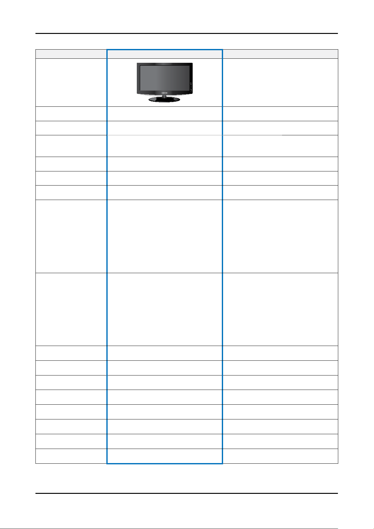
2-3. Spec Comparison to the Old Models
Model LN**A450C1D(19”/22”/26”/32”/37”/40”) LNT**42H (23”/26”/32”/40”/46”)
Design
Display Type LCD TV LCD TV
Built-in Tuner O O
19”=>1440 x 900
Resolution
LCD Panel TFT LCD Panel 60Hz TFT LCD Panel 60Hz
Screen Size 19”/22”/26”/32”/37”/40” 23” / 26” / 32” / 40” / 46”
Picture ratio 16 : 9 16 : 9
18.78 x 7.09 x 15.24 inches_with stand
19
22
26
Dimensions (W x H x D)
31.48 x 11.81 x 25.91 inches_with stand
32
36.08 x 11.81 x 25.91 inches_with stand
37
38.97 x 11.81 x 27.33 inches_with stand
40
22”=>1680 x 1050
26”/32”/37”/40”=>1366x768
21.96 x 8.5 x 17.83 inches_with stand
26.37 x 8.5 x 19.7 inches_with stand
1366 x 768
26.29 x 9.13 x 17.53 inches_with stand
23
29.28 x 9.15 x 19.94 inches_with stand
26
34.42 x 11.47 x 22.72 inches_with stand
32
42.67 x 11.81 x 27.17 inches_with stand
40
48.04 x 12.83 x 30.55 inches_with stand
46
19
22
26
Weight
32
37
40
Brightness 500nit (19”=>300nit) 500 nit
Contrast Ratio 8000:1 (19”=>1000:1) 8000:1
Picture Enhacer DNIe(FBE3) DNIe (FBE2)
Equalizer 5 band 5 band
Auto Motion Plus 120Hz Not available Not available
Surround Sound 2 Way SRS TruSurround Dolby Digital 2 Way SRS TruSurround Dolby Digital
Speaker Output 5W x 2 5W x 2
Antenna 1 (Cable/Air) 2 (Cable/Air)
11.24 lbs(set)
16.09 lbs(set)
21.38 lbs(set)
28.88 lbs(set)
40.34 lbs(set)
41 lbs(set)
23
26
32
40
46
24.25 lbs (set)
31.97 lbs (set)
41.89 lbs (set)
60.63 lbs (set)
80.91 lbs (set)
2-4
Page 12

2-4. Accessories
Product Description Code. No Remark
2. Product specications
Remote Control & Batteries
(AAA x 2)
Power Cord 3903-000144
Cover-Bottom BN63-04243A
Owner’s Instructions BN63-01395B
Cleaning Cloth BN63-01798A
Warranty Card / Registration
Card / Safety Guide Manual
(Not available in all locations)
BN59-00599A
6801-001011
Samsung Electronics
Service center
2-5
Page 13

4. Troubleshooting
Power Board
Main Board
Panel
4-1. Troubleshooting
Check the various cable connections rst.
1.
• Check to see if there is a burnt or damaged cable.
• Check to see if there is a disconnected or loose cable connection.
• Check to see if the cables are connected according to the connection diagram.
Check the power input to the Main Board.
2.
4. Troubleshooting
4-1
Page 14

4. Troubleshooting
4-1-1. No Power
-
Symptom
Major
checkpoints
-
-
The IP relay or the LEDs on the front panel does not work when connecting the power cord if the cables are
improperly connected or the Main Board or SMPS is not functioning. In this case, check the following:
-
-
-
-
The LEDs on the front panel do not work when connecting the power cord.
The SMPS relay does not work when connecting the power cord.
The units appears to be dead.
Check the internal cable connection status inside the unit.
Check the fuses of each part.
Check the output voltage of SMPS.
Replace the Main Board.
Diagnostics
Lamp(Backlight) Off, power indicator
LED on?
Yes
Does proper Stand-By DC
A5V appear at C223?
Yes
Does proper Main DC B10V_S, B5V,
B13V appear at BD221, C273C C278?
Yes
Does proper Inverter DC 120V appear
at CN101 in SMPS?
Yes
Does proper DC A3.3V appear at D206?
Yes
Does proper DC B3.3V appear at
R203?
Yes
Does proper A1.2V appear at C208?
No
No
No
No
No
No
No
Check a connection power cable.
P/N : BP39-00028A
Change the Main Power assembly
19” => BN44-00152B
22” => BN44-00152A
Check IC203 Change the Main Ass`y
19” : BN94-01638A
22” : BN94-01638B
Check IC203
Change the Main Ass`y
19” : BN94-01638A
22” : BN94-01638B
Check IC402
Change the Main Ass`y
19” : BN94-01638A
22” : BN94-01638B
4-2
Caution
Make sure to disconnect the power before working on the IP board.
Page 15

4-1-2. No Video (Analog PC signal)
Symptom Audio is normal but no picture is displayed on the screen.-
-
Major
checkpoints
Check the PC source
-
Check the MSD2248AL
This may happen when the LVDS cable connecting the Main Board and the Panel is disconnected.
-
4. Troubleshooting
Diagnostics
Power Indicator is off.
Lamp(Backlight) Off, no video
Yes
Check the PC source and
check the connection of DSUB?
Yes
Does the signal appear at
1
2
3
#w1, #u1, #AB2, #F1, #G1
(R, G, B, H, V) of IC402?
Yes
Does the digital data appear at output of
R452, R453, R402, R403, R404?
Yes
Does the digital data appear at output
of C609 and C610?
Yes
Check the LVDS cable?
Replace the LCD panel?
No
No
No
No
No
Input an analog PC signal.
Check the connected cable.
Check IC601, PC cable.
Change the PC cable. Change the main
PCB assembly
Check IC402 Change the main PCB
assembly
Check IC402
Change the main PCB assembly
Please, Contact Tech support
Caution Make sure to disconnect the power before working on the IP board.
4-3
Page 16

4. Troubleshooting
WAVEFORMS
1 2
3
PC Input (V-Sync, H-Sync)
LVDS Out (CLK + / -)
4-4
Page 17

4-1-3. No Video (HDMI - Digital Signal)
Symptom Audio is normal but no picture is displayed on the screen.-
-
Major
checkpoints
Check the HDMI source
-
Check the MSD2248AL
This may happen when the LVDS cable connecting the Main Board and the Panel is disconnected.
-
4. Troubleshooting
Power Indicator is off.
Lamp(Backlight) Off, no video
Yes
Diagnostics
Caution Make sure to disconnect the power before working on the IP board.
Check the HDMI source and check
the connection of HDMI cable?
Yes
4
Does the digital data appear at output of
7
R659, R660(CLK+/-),
R661~R666(DATA)?
Yes
R452, R453, R402, R403, R404?
Yes
Check the LVDS cable?
Replace the LCD panel?
No
No
No
No
Input an HDMI signal.
Check the connected cable.
Check U601, HDMI cable.
Change the HDMI cable. Change
the main PCB assembly
Check IC4001
Change the main PCB assembly
Please, Contact Tech support
4-5
Page 18

4. Troubleshooting
WAVEFORMS
4 5
6
HDMI Input (CLK + / -)
Tuner CVBS Out (Pattern: Grey Bar)
7
TS DATA Out (Clk, Data [0])
4-6
Page 19
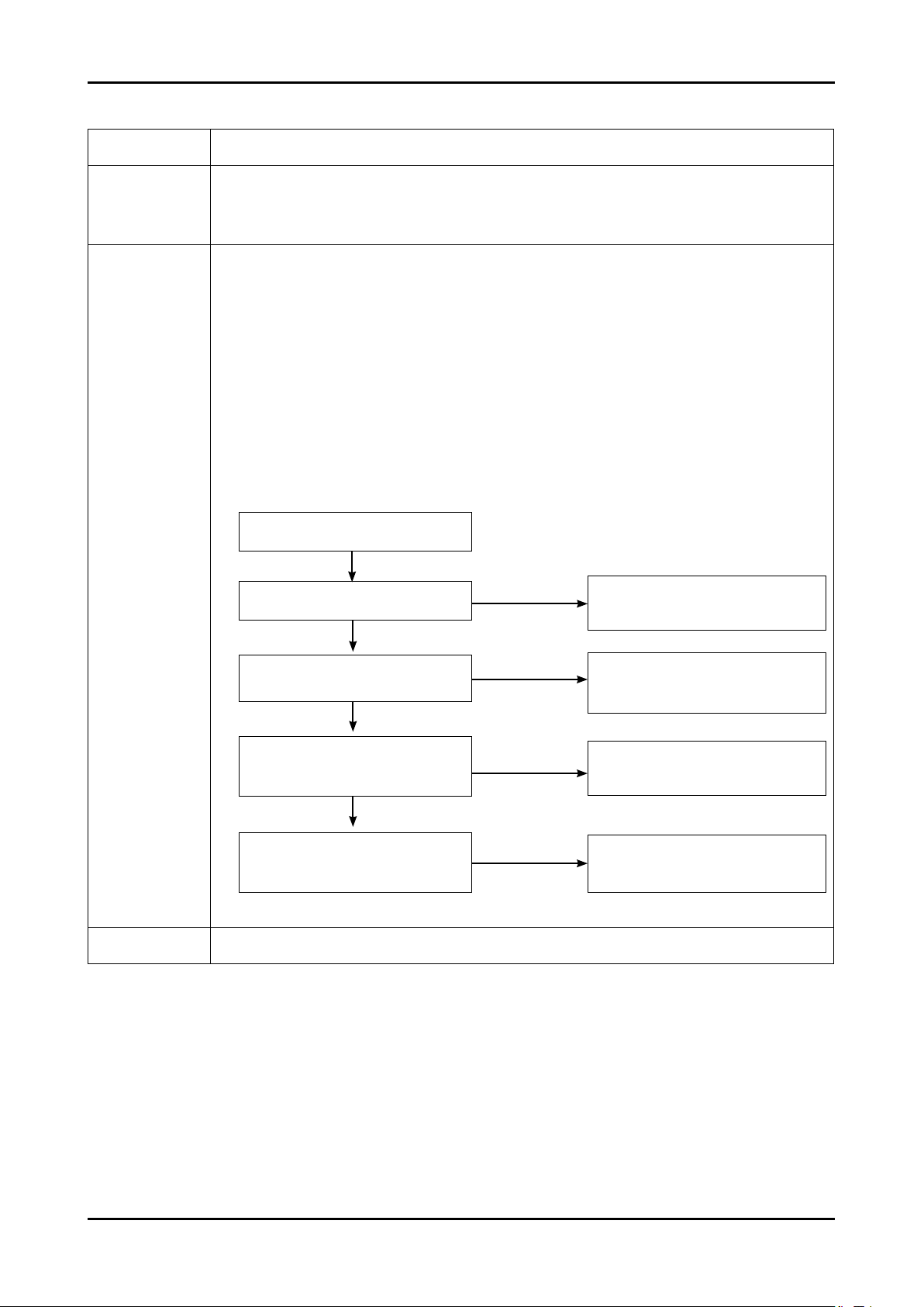
4-1-4. No Video (Tuner_CVBS)
Symptom Audio is normal but no picture is displayed on the screen.-
-
Major
checkpoints
Check the Tuner CVBS source
-
Check the MSD2248AL
This may happen when the LVDS cable connecting the Main Board and the Panel is disconnected.
-
4. Troubleshooting
Power Indicator is off.
Lamp(Backlight) Off, no video
Yes
Diagnostics
8
6
Caution Make sure to disconnect the power before working on the IP board.
Check the RF source and
check the connection of RF cable?
Yes
Does the signal appear at TU501?
Yes
Does the digital data appear at output
of C503, C504, R452, R453, R402,
R403, R404?
Yes
Check the LVDS cable?
Replace the LCD panel?
No
No
Change the main PCB assembly or tuner.
No
No
Input the RF signal.
Check the connected cable.
Check TU501
Check IC4001
Change the main PCB assembly
Please, Contact Tech support
4-7
Page 20
4. Troubleshooting
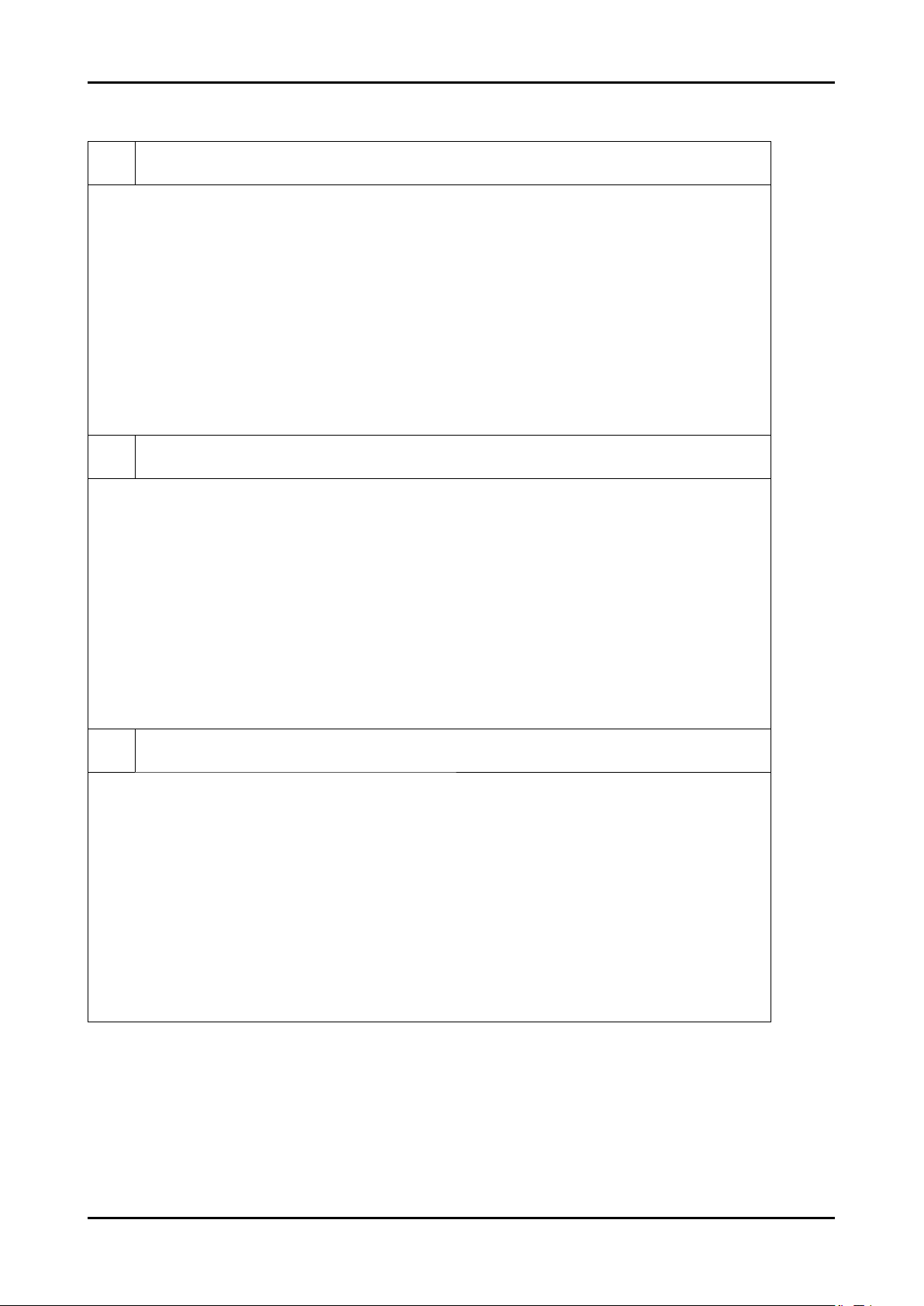
WAVEFORMS
Tuner CVBS Out (Pattern: Grey Bar)
6
TS DATA Out (Clk, Data [0])
7
Eagle+ Out (Clk, H-Sync)
8
4-8
Page 21
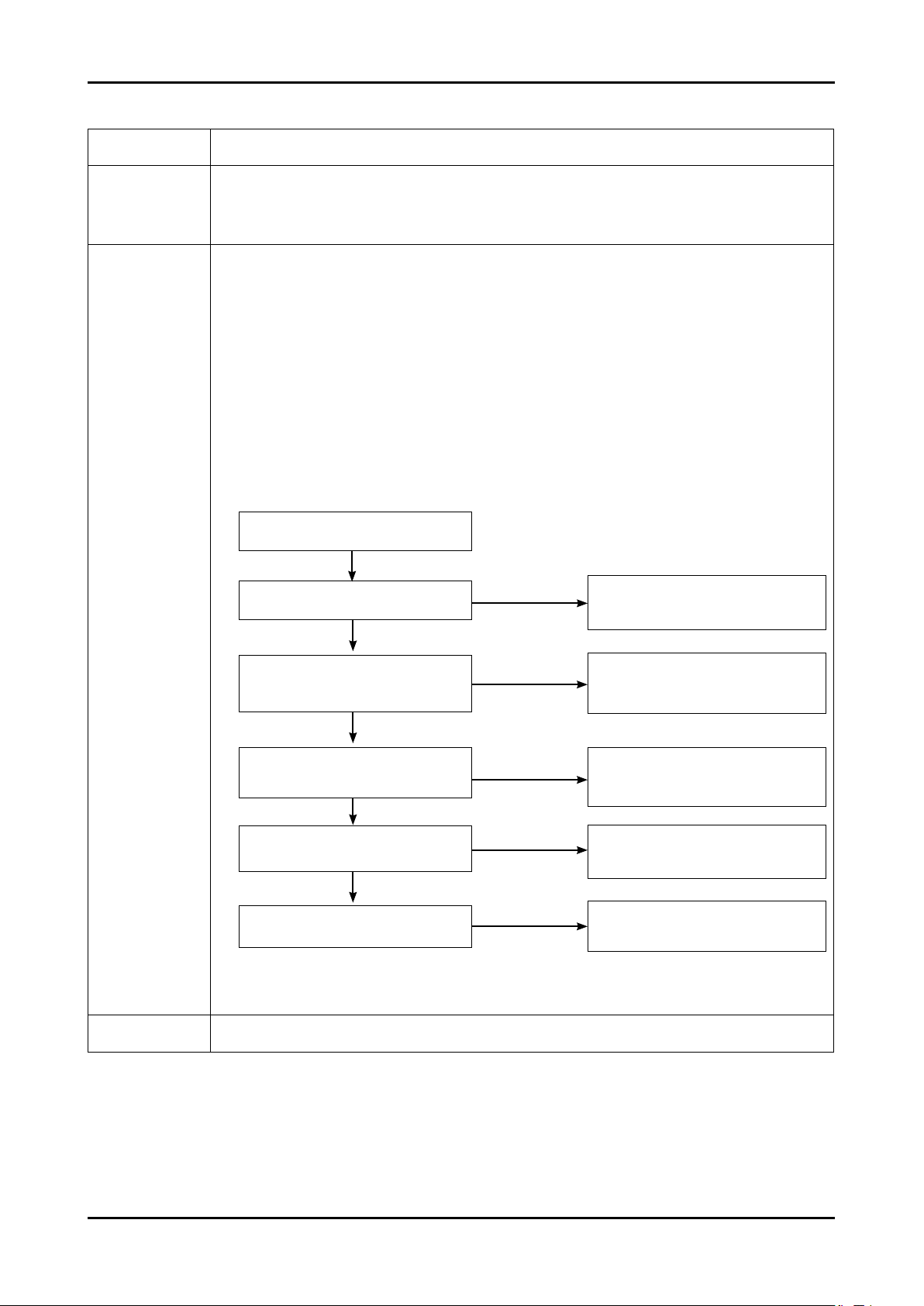
4-1-5. No Video (Tuner DTV)
Symptom Audio is normal but no picture is displayed on the screen.-
-
Major
checkpoints
Check the DTV source
-
Check the MSD2248AL
This may happen when the LVDS cable connecting the Main Board and the Panel is disconnected.
-
4. Troubleshooting
Diagnostics
Power Indicator is off.
Lamp(Backlight) Off, no video
Yes
Check the RF source and
check the connection of RF cable?
Yes
7
6
7
Does the digital data appear
at C510, C511?
Yes
Does the digital data appear at output
of R522~R529?
Yes
Does the digital data appear at output
of R452, R453, R402, R403, R404?
Yes
Check the LVDS cable?
Replace the LCD panel?
No
No
No
No
No
Input the RF signal.
Check the connected cable.
Check TU501
Change the main PCB assembly
or tuner.
Check IC502
Change the main PCB assembly
Check IC4001
Change the main PCB assembly
Please, Contact Tech support
Caution Make sure to disconnect the power before working on the IP board.
4-9
Page 22
4. Troubleshooting
WAVEFORMS
Tuner CVBS Out (Pattern: Grey Bar)
6
TS DATA Out (Clk, Data [0])
7
Eagle+ Out (Clk, H-Sync)
8
4-10
Page 23
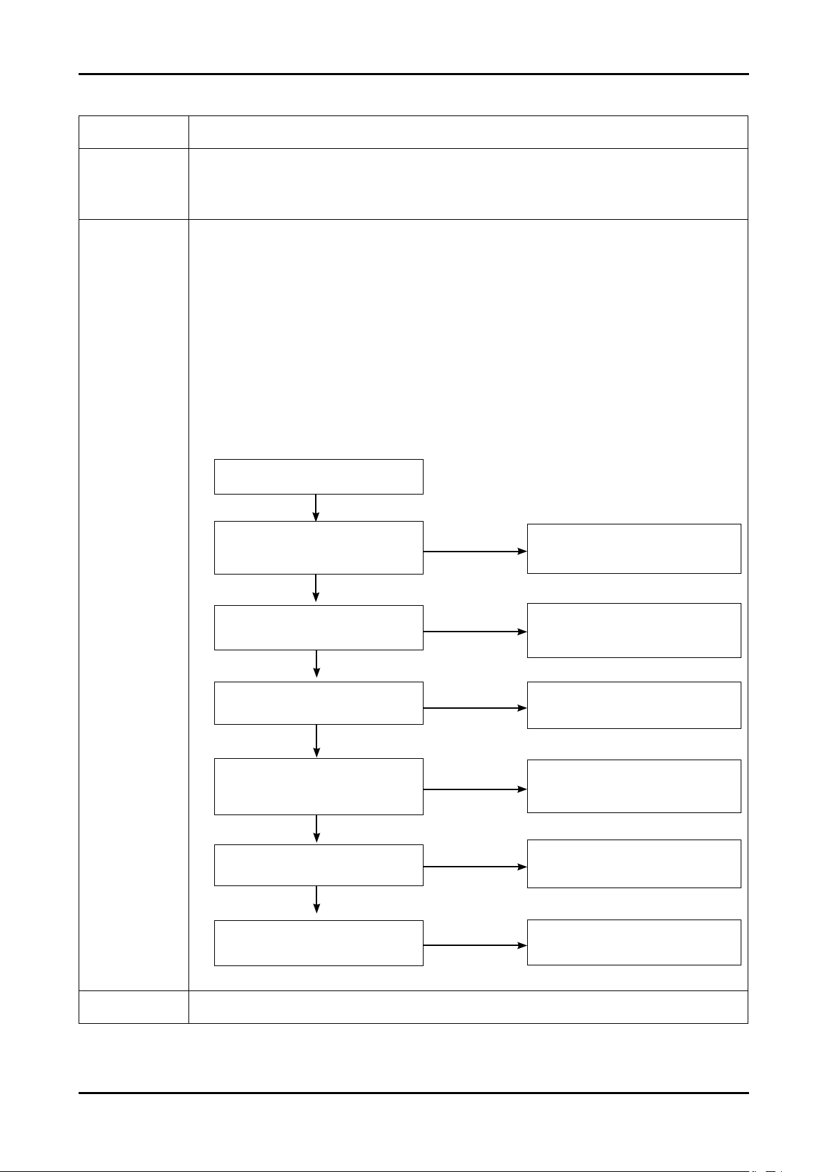
4-1-6. No Video (Video CVBS)
Symptom Audio is normal but no picture is displayed on the screen.-
-
Major
checkpoints
Check the Video CVBS source
-
Check the MSD2248AL
This may happen when the LVDS cable connecting the Main Board and the Panel is disconnected.
-
4. Troubleshooting
Diagnostics
Power Indicator is off.
Lamp(Backlight) Off, no video
Yes
Check the video source and
check the connection of
video cable?
Yes
Does the signal appear at R626~R629?
6
Yes
Does the signal appear at R348?
Yes
Does the digital data appear at output
6
Does the digital data appear at output
7
of R452, R453, R402, R403, R404?
of R522~R529?
Yes
No
No
No
No
No
Input a video signal.
Check the connected cable.
Check CN604
Change the main PCB ass’y or
Side-AV Ass’y
Check IC4001
Check IC4001
Change the main PCB assembly
Check IC4001
Change the main PCB assembly
Yes
Check the LVDS cable?
Replace the LCD panel?
Caution Make sure to disconnect the power before working on the IP board.
No
Please, Contact Tech support
4-11
Page 24
4. Troubleshooting
WAVEFORMS
Tuner CVBS Out (Pattern: Grey Bar)
6
TS DATA Out (Clk, Data [0])
7
4-12
Page 25
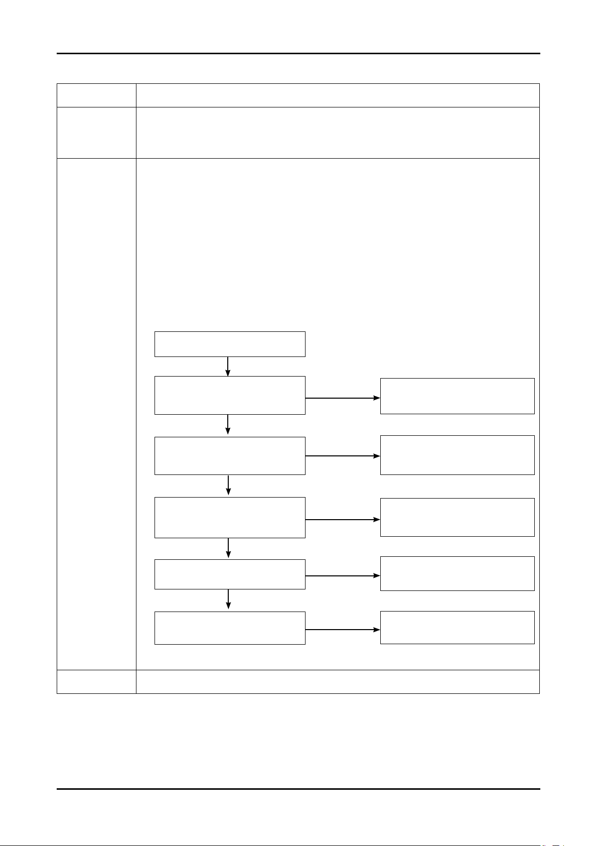
4-1-7. No Video (S-Video)
Symptom Audio is normal but no picture is displayed on the screen.-
-
Major
checkpoints
Check the S-Video source
-
Check the MSD2248AL
This may happen when the LVDS cable connecting the Main Board and the Panel is disconnected.
-
4. Troubleshooting
Diagnostics
Power Indicator is off.
Lamp(Backlight) Off, no video
Yes
Does the digital data appear at output
of R522~R529?
Yes
9
6
7
Does the signal appear
at R452, R453, R402, R403, R404?
Yes
Does the digital data appear at output
of R452, R453, R402, R403, R404?
Yes
Does the digital data appear at output
of R452, R453, R402, R403, R404?
Yes
Check the LVDS cable?
Replace the LCD panel?
No
No
No
No
No
Input a video signal.
Check the connected cable.
Check CN605 or Side-AV
Change the main PCB ass’y or
Side-AV assembly
Check IC4001
Change the main PCB assembly
Check IC4001
Change the main PCB assembly
Please, Contact Tech support
Caution Make sure to disconnect the power before working on the IP board.
4-13
Page 26
4. Troubleshooting
WAVEFORMS
Tuner CVBS Out (Pattern: Grey Bar)
6
TS DATA Out (Clk, Data [0])
7
S-VIDEO Input (Y/C)
9
4-14
Page 27
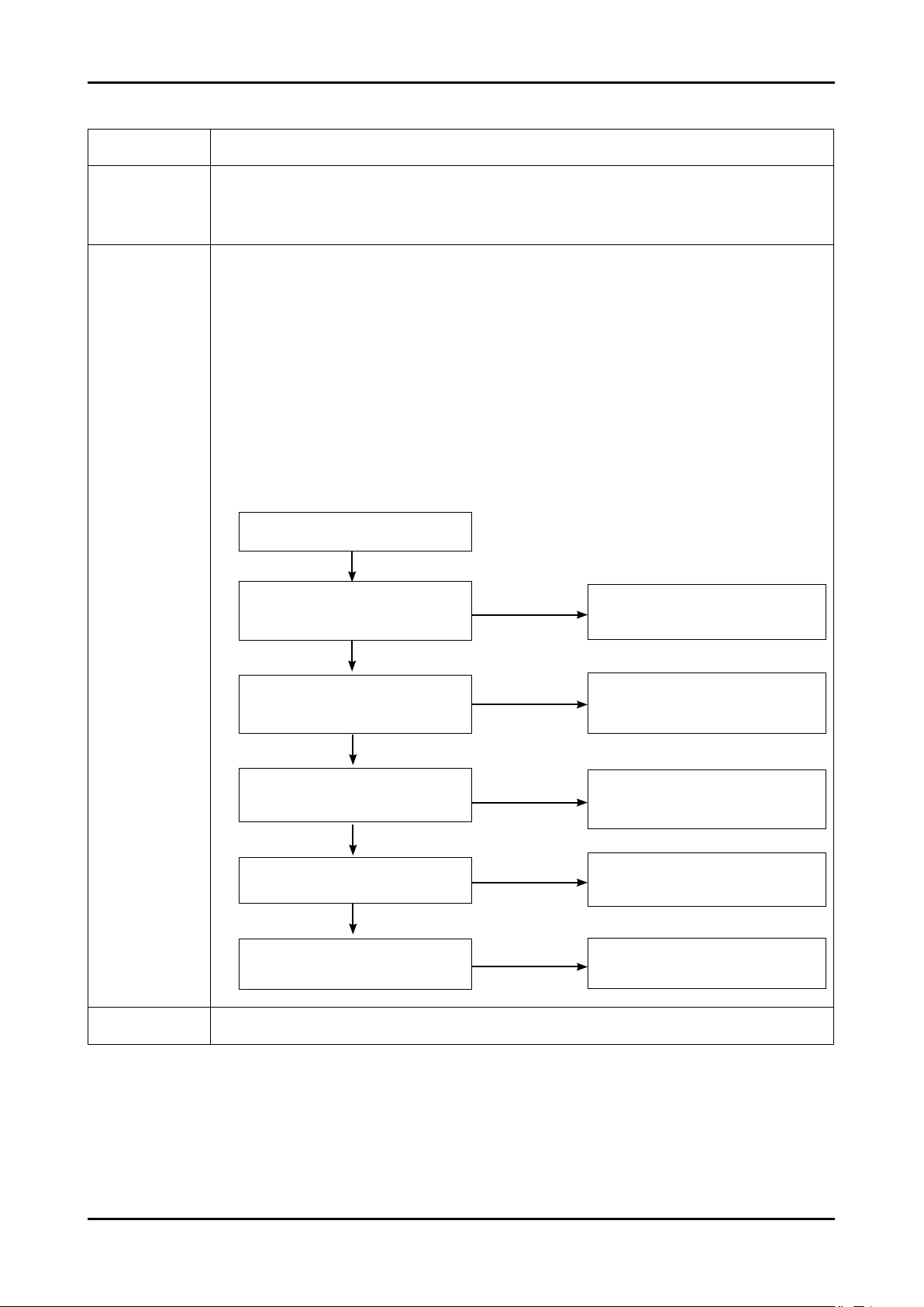
4-1-8. No Video (Component)
Symptom Audio is normal but no picture is displayed on the screen.-
-
Major
checkpoints
Check the Component source
-
Check the MSD2248AL
This may happen when the LVDS cable connecting the Main Board and the Panel is disconnected.
-
Power Indicator is off.
Lamp(Backlight) Off, no video
4. Troubleshooting
Yes
Check component source and
Diagnostics
0
6
7
Caution Make sure to disconnect the power before working on the IP board.
check the connection of
component cable ?
Yes
Does the signal appear at
R620, R621, R622(Y,Pb,Pr)?
Yes
Does the digital data appear at output
of R522~R529?
Yes
Does the digital data appear at output
of R452, R453, R402, R403, R404?
Yes
Check the LVDS cable?
Replace the LCD panel?
No
No
No
No
No
Input a component signal.
Check the connected cable.
Check JA602
Change the main PCB ass’y
Check IC4001
Change the main PCB assembly
Check IC4001
Change the main PCB assembly
Please, Contact Tech support
4-15
Page 28
4. Troubleshooting
WAVEFORMS
Tuner CVBS Out (Pattern: Grey Bar)
6
TS DATA Out (Clk, Data [0])
7
Component Input (Y/Pb)
0
4-16
Page 29
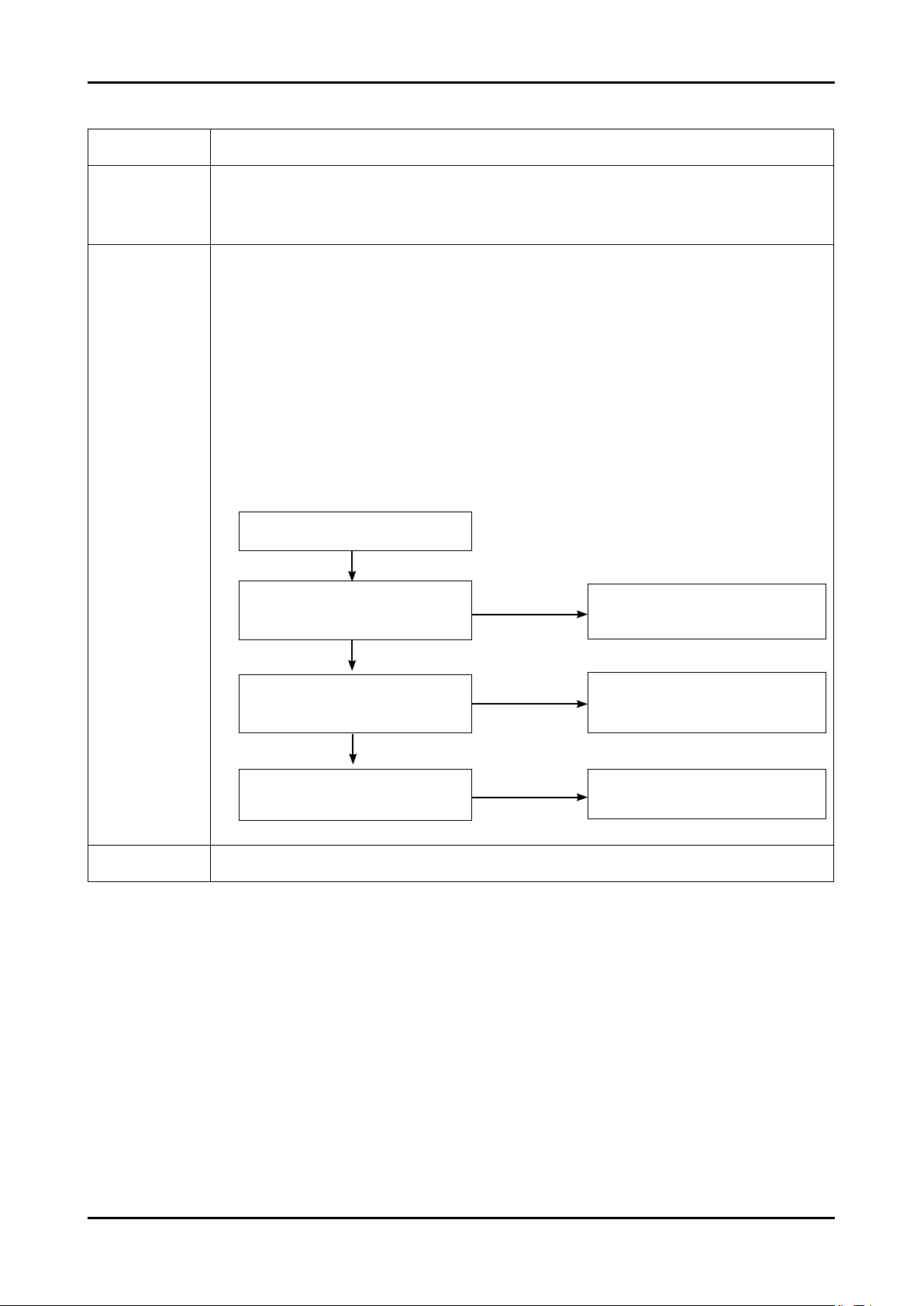
4-1-9. No Sound
Symptom Video is normal but there is no sound..-
Major
checkpoints
-
-
-
4. Troubleshooting
When the speaker connectors are disconnected or damaged.
When the sound processing part of the Main Board is not functioning.
Speaker defect..
Diagnostics
Caution Make sure to disconnect the power before working on the IP board.
Lamp(Backlight) Off, no sound.
Yes
Check the sound source and
check the connection of
sound cable?
Yes
Does the signal appear at R607, R608,
!
R628, R629, R669~R672, R686,
R687(VIDEO2,COMP,PC,DVI,HP)?
Yes
Check the LVDS cable?
Replace the LCD panel?
No
No
No
Input a sound signal.
Check the connected cable.
Check IC4001
Change the main PCB ass’y or
side-AV assembly
Please, Contact Tech support
4-17
Page 30
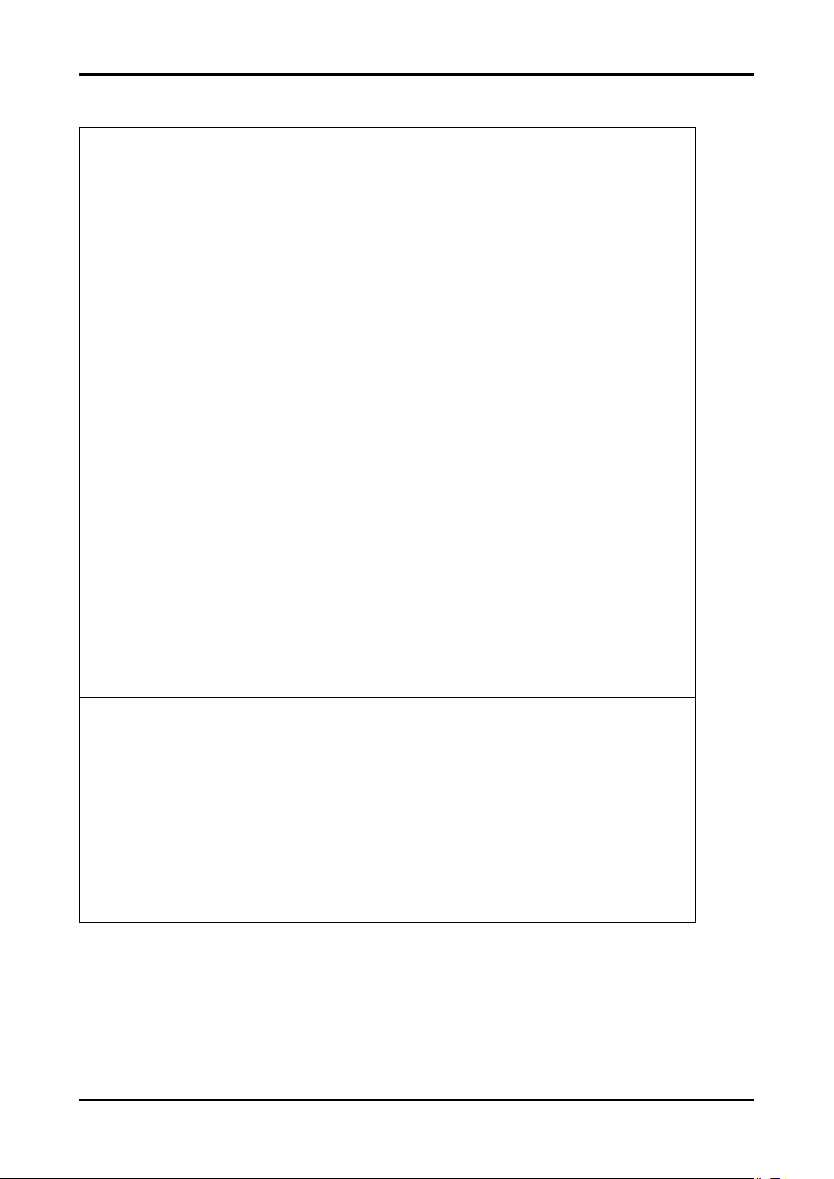
4. Troubleshooting
WAVEFORMS
Audio Input (Sign Wave)
!
12S Input (Clk, Data)
@
Audio Amp Out (Sign Wave)
#
4-18
Page 31

4-2. Alignments and Adjustments
4-2-1. General Alignment Instuction
Usually, a color LCD-TV needs only slight touch-up adjustment upon installation.
1.
Check the basic characteristics such as height, horizontal and vertical sync.
Use the specied test equipment or its equivalent.
2.
Correct impedance matching is essential.
3.
Avoid overload. Excessive signal from a sweep generator might overload the front-end
4.
of the TV. When inserting signal markers, do not allow the marker generator to distort test result.
Connect the TV only to an AC power source with voltage and frequency as specied on
5.
the backcover nameplate.
Do not attempt to connect or disconnect any wire while the TV is turned on. Make sure
6.
that the power cord is disconnected before replacing any parts.
To protect against shock hazard, use an isolation transformer.
7.
4. Troubleshooting
4-19
Page 32
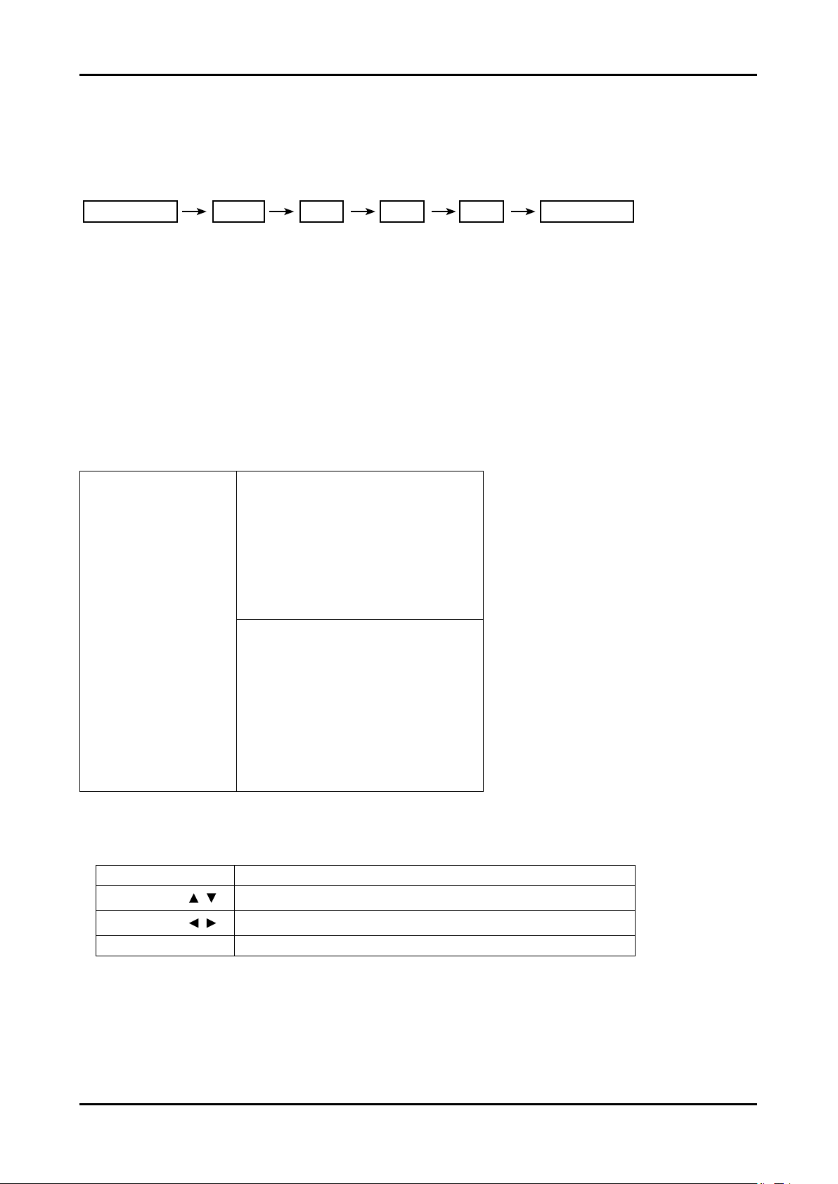
4. Troubleshooting
4-3. Factory Mode Adjustments
4-3-1 Entering Factory Mode
To enter ‘Service Mode’ Press the remote -control keys in this sequence :
- If you do not have Factory remote - control
Power OFF 1 8 2 Power On
MUTE
4-3-2 How to Access Service Mode
Using the Customer Remote
1.
Turn the power off and set to stand-by mode
2.
Press the remote buttons in this order; POWER OFF-MUTE-1-8-2-POWER ON to turn the set on.
3.
The set turns on and enters service mode. This may take approximately 20 seconds.
4.
Press the Power button to exit and store data in memory.
- If you fail to enter service mode, repeat steps 1 and 2 above.
5.
Initial SERVICE MODE DISPLAY State
- The mother page of Factory mode => Blue letter is a real displayed data
ADC
ADC Target
ADC Value
Option BYTE
ADJUST
W/B
W/B Movie
EPA standard
FBE3
VDEC
Scaler
Sharpness
PE
Sound
Dynamic Contrast
PDP Option
Expert Settings
Expert D-Settings
Expert Gray Scale
Expert C-Space
Expert Others
CHECKSUM
RESET
T-CRLAUSC-00xx
0050 6628 00CD 1510
Micom / VER. / Month/ Day / Year
- “T-PEONAUSC-1000” and “T-PEONASS-1000” are rmware.......
over version 2000 means Micronas FRC rmware.
Buttons operations withn Service Mode
1.
Menu Full Menu Display/Move to Parent Menu
Direction Keys
Direction Keys
4-20
Source
Item Selection by Moving the Cursor
/
Data Increase / Decrease for the Selected Item
/
Cycles through the active input source that are connected to the unit
Page 33
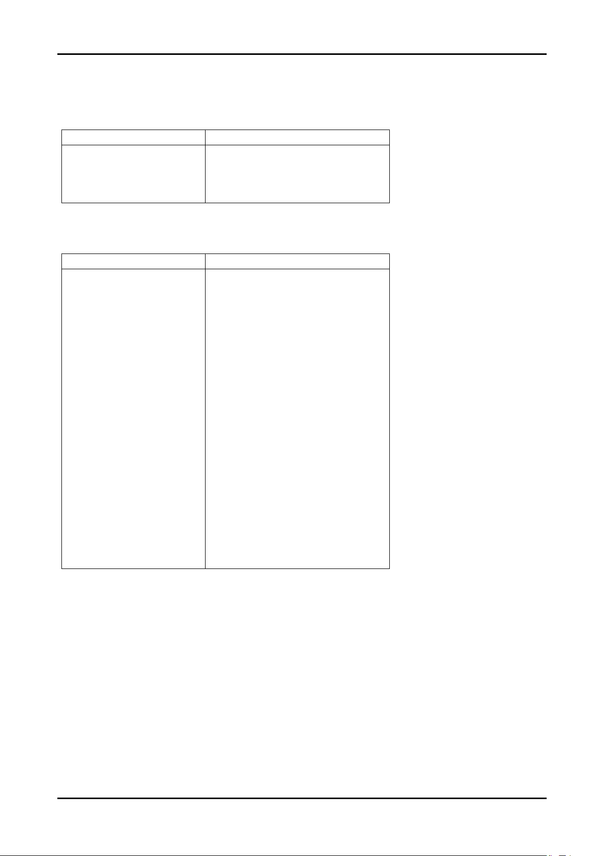
4-3-3 Factory Data
- The sub_page of Factory mode
ADC
Name Default data
AV Calibration
Component Calibration
PC Calibration
HDMI Calibration
ADC Target
Name Default data
1st_AV_Low
1st_AV_High
1st_AV_Delta
1st_COMP_Low
1st_COMP_High
1st_COMP_Delta
1st_PC_Low
1st_PC_High
1st_PC_Delta
2nd_AV_Low
2nd_AV_High
2nd_AV_Delta
2nd_COMP_Low
2nd_COMP_High
2nd_COMP_Delta
2nd_PC_Low
2nd_PC_High
2nd_PC_Delta
2nd_HDMI_Low
2nd_HDMI_High
2nd_HDMI_Delta
4. Troubleshooting
-
-
-
-
18
220
1
16
235
1
1
235
1
1
235
1
1
235
1
1
235
1
1
235
1
4-21
Page 34
4. Troubleshooting
ADC Value
Name Default data
LUMA_OFFSET
LUMA_GAIN
RED_CUTOFF
GREEN_CUTOFF
BLUE_OFFSET
RED_GAIN
GREEN_GAIN
BLUE_GAIN
2nd_R offset
2nd_G offset
2nd_B offset
2nd_R gain
2nd_G gain
2nd_B gain
128
128
128
128
128
128
128
128
128
128
128
128
128
128
Option Byte
COMP. Number
Anynet+(HDMI-CEC)
Mute Time[RF]
PC Mode Ident
PANEL ENTER KEY
Name Default data
LCD/PDP
Inch
Panel Option
Dimming
Mirror
AV Number
HDMI Number
Light Effect
HeadPhone
Carrier Mute
Volume Curve
Caption Level
RS 232C
Gamma
CH Memory
Shop Mode
HPD Control
7.5IRE Set
7.5IRE Offset
HDMI 1080p
EER Count
Expert ADJ.
Auto wall
SAMEX
LCD
xx Inch
xxAM
INT
OFF
2
2
3
ON
ON
ON
OFF
ON
ON
0.85
600mS
OFF
Auto
OFF
ON
0
OFF
ON
11
OFF
4-22
Page 35
Adjust
Name Default data
Watchdog Enable
Watchdog Count
Spread Spectrum
Shop Mode
DEBUG MODE
LVDS Format
White Balance (Available over 26 inches. (With FBE3))
Name Default data
Sub Brightness
R-Offset
G-Offset
B-Offset
Sub Contrast
R-Gain
G-Gain
B-Gain
ON
10sec
OFF
OFF
DEBUG OFF
VESA
128
128
128
128
128
128
128
128
4. Troubleshooting
White Balance Available 19 & 22 inches.( Without FBE3)
Name Default data
Sub Brightness
R-Offset
G-Offset
B-Offset
Sub Contrast
R-Gain
G-Gain
B-Gain
White Balance Available only PDP.
Name Default data
Sub Brightness
R-Offset
G-Offset
B-Offset
Sub Contrast
R-Gain
G-Gain
B-Gain
128
128
128
128
128
128
128
128
128
128
128
128
128
128
128
128
4-23
Page 36
4. Troubleshooting
Adjust
Name Default data
W/B MOVIE
MODE
Color Tone
MSub Brightness
MSub Contrast
W2_Rgain
W2_Bgain
W2_Roffset
W2_Boffset
W1_Rgain
W1_Bgain
W1_Roffset
W1_Boffset
NOR_Rgain
NOR_Bgain
NOR_Roffset
NOR_Boffset
C2_Rgain
C2_Bgain
C2_Roffset
C2_Boffset
Movie Contrast
Movie Bright
Movie Color
Movie Sharpness
Movie Tint
Movie Backlight
Movie Gamma
on
Dynamic
Cool1
128
128
19
-26
-1
4
49
-43
-4
4
7
-11
-2
2
-32
22
5
1
70
50
25
45
0
5
off
EPA Standard
Standard Contrast
Standard Brightness
Standard Sharpness
Standard Color
Standard Tint
Standard Backlight
4-24
Name Default data
80
45
50
50
0
7
Page 37
FBE3
Name Default data
Patt-Sel
B-Slope gain
B-Tilt min
B-Tilt max
Lfunc-Basis
Hfunc-Basis
Mean-Offset1
Mean-Offset2
Mean-Slope
ACR-Offset
ACR-Th1
ACR-Th2
Skin-Enable
Skin-UV
Sub color
M-Skin-UV
M-Sub color
Input Format
Output Format
4. Troubleshooting
0
60
30
110
75
80
30
235
112
10
10
110
ON
128
128
128
128
VESA
VESA
VDEC
Scaler
Name Default data
Saturation
CTI_MD
CBCRLP_MD
Name Default data
DNR_off
DNR_low
DNR_mid
DNR_high
Y_DELAY_EN
YC_STEP
80
2
1
0
2
3
4
1
1
4-25
Page 38
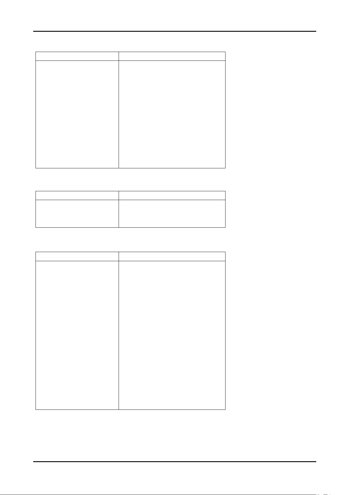
4. Troubleshooting
Sharpness
Name Default data
H1 Gain
H2 Gain
H3 Gain
H4 Gain
V1 Gain
V2 Gain
H overshoot
V overshoot
H undershoot
V undershoot
Coring TH2
Coring TH1
Mid_color_level
PE
10
8
8
8
28
8
FF
60
FF
60
1
1
AC
Sound
Name Default data
Skin_EN
D_Skin
M_Skin
Name Default data
Carrier Mute
High DEV
CM_TH_HIGH
CM_TH_LOW
ST_PILOT_TH_HIGH
ST_PILOT_TH_LOW
ST_VAR_TH_HIGH
ST_VAR_TH_LOW
SAP_AMP_TH_HIGH
SAP_AMP_TH_LOW
SAP_NSR_TH_HIGH
SAP_NSR_TH_LOW
AMP_Volume
AMP_Limiter_Attack
AMP_Limiter_Release
AMP_Post-Scale
AMP_Speaker EQ
AV Sync.
1
12
12
1
0
2990
20B0
D00
600
1800
1000
1
4
4500
3000
29
9
F
5C
0
0
4-26
Page 39
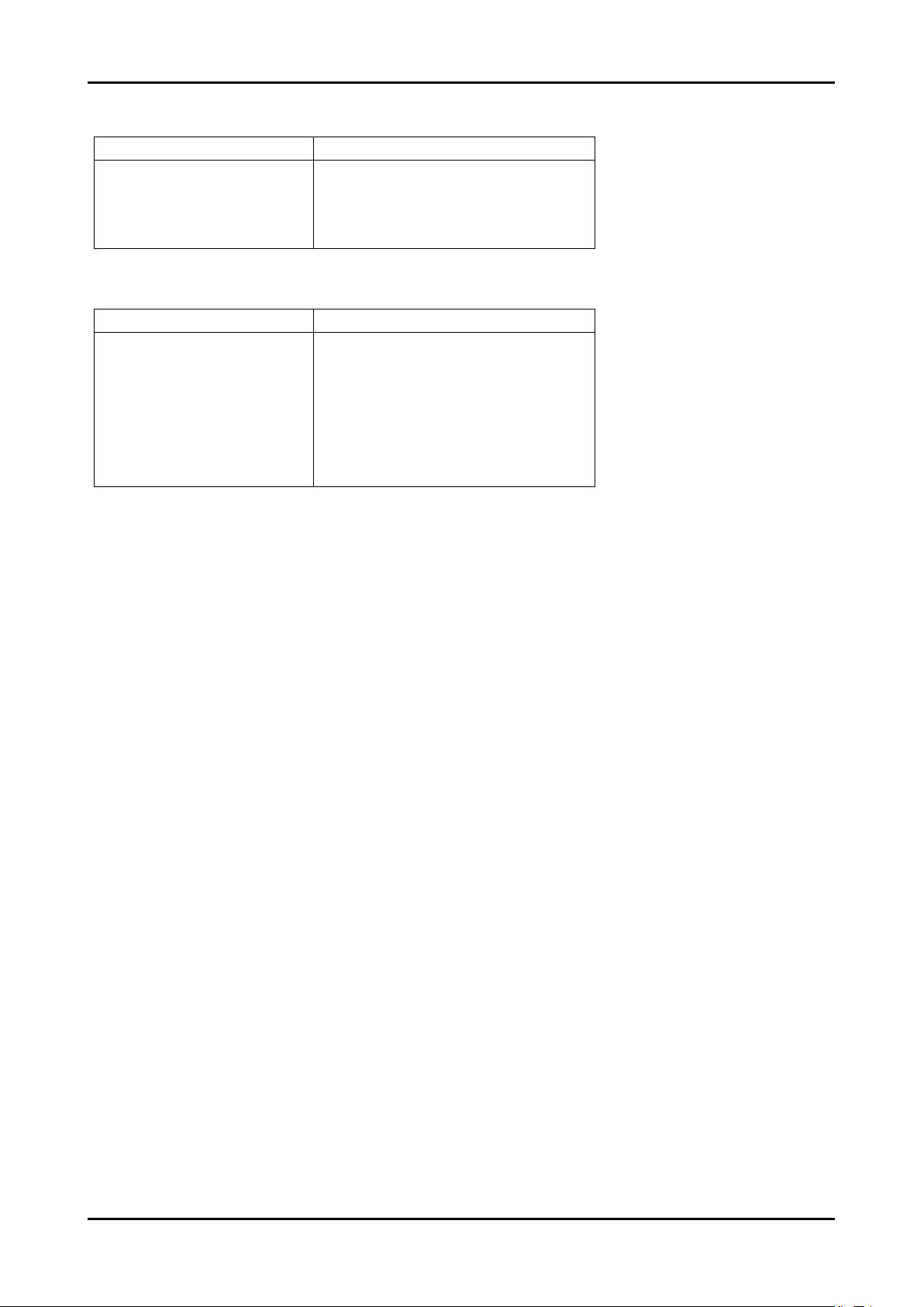
Dynamic Contrast
Name Default data
4. Troubleshooting
Dynamic Contrast
Dynamic Dimming
Y_MEAN
Checksum
Name Default data
Checksum
After execute CHECKSUM
CHECKSUM
Main : 0xB018
Back: Press Menu Key
Reset
On
off
0
0x0000
4-27
Page 40
4. Troubleshooting
4-4. White Balance - Calibration
4-4-1 White Balance -Calibration
1. Calibration
4-4-2 Service Adjustment -
Color Calibration
Adjust spec.
1. Source : HDMI
2. Setting Mode : 1280*720@60Hz
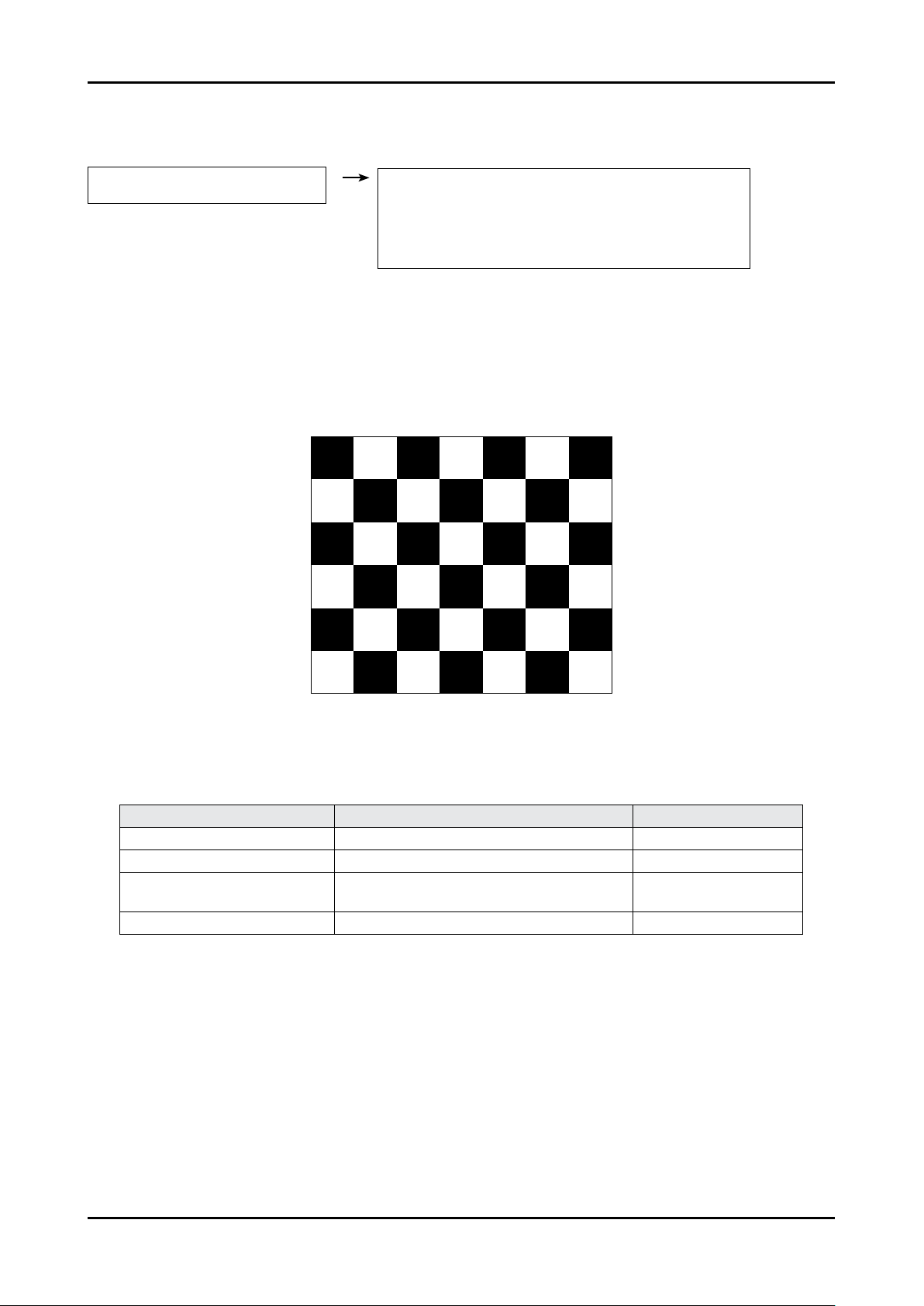
3. Pattern : Pattern #24 (Chess Pattern)
You must perform Calibration in the Lattice Pattern before adjusting the White Balance.
AV Calibration
Comp Calibration
PC Calibration
HDMI Calibration
( Chess Pattern )
4. Use Equipment : CA210 & Master MSPG925 Generator
- Use other equipment only after comparing the result with that of the Master equipment.
Input mode Calibration Pattern
CVBS IN (Model_#1) Perform in NTSC B&W Pattern #24 Lattice
Component IN (Model_#6) Perform in 720p B&W Pattern #24 Lattice
PC Analog IN (Model_#21)
HDMI IN Perform in 720p B&W Pattern #24 Lattice
Perform in VESA XGA (1024x768)
B&W Pattern #24
<Table 1>
Lattice
4-28
Page 41
Method of Color Calibration (AV)
1) Apply the NTSC Lattice (N0. 3) pattern signal to the AV IN 1 port
2) Press the Source key to switch to “AV1” mode
3) Enter Service mode
4) Select the “Calibration” menu
5) Select the “AV Calibration” menu.
6) In “AV Calibration Off” status, press the “
7) When Calibration is complete, it returns to the high-level menu.
8) You can see the change of the “AV Calibration” status from Failure to Success.
Method of Color Calibration (Component)
1) Apply the 720p Lattice (N0. 6) pattern signal to the Component IN 1 port
2) Press the Source key to switch to “Component1” mode
3) Enter Service mode
4) Select the “Calibration” menu
5) Select the “Comp Calibration” menu.
6) In “Comp Calibration Off” status, press the “
7) When Calibration is complete, it returns to the high-level menu.
8) You can see the change of the “Comp Calibration” status from Failure to Success.
Method of Color Calibration (PC)
1) Apply the VESA XGA Lattice (N0. 21) pattern signal to the PC IN port
2) Press the Source key to switch to “PC” mode
3) Enter Service mode
4) Select the “Calibration” menu
5) Select the “PC Calibration” menu.
6) In “PC Calibration Off” status, press the “
7) When Calibration is complete, it returns to the high-level menu.
8) You can see the change of the “PC Calibration” status from Failure to Success.
” key to perform Calibration.
” key to perform Calibration.
” key to perform Calibration.
4. Troubleshooting
Method of Color Calibration (HDMI)
1) Apply the 720p Lattice (N0. 6) pattern signal to the HDMI1/DVI IN port
2) Press the Source key to switch to “HDMI1” mode
3) Enter Service mode
4) Select the “Calibration” menu
5) Select the “HDMI Calibration” menu.
6) In “HDMI Calibration Off” status, press the “
7) When Calibration is complete, it returns to the high-level menu.
8) You can see the change of the “HDMI Calibration” status from Failure to Success.
” key to perform Calibration.
4-29
Page 42
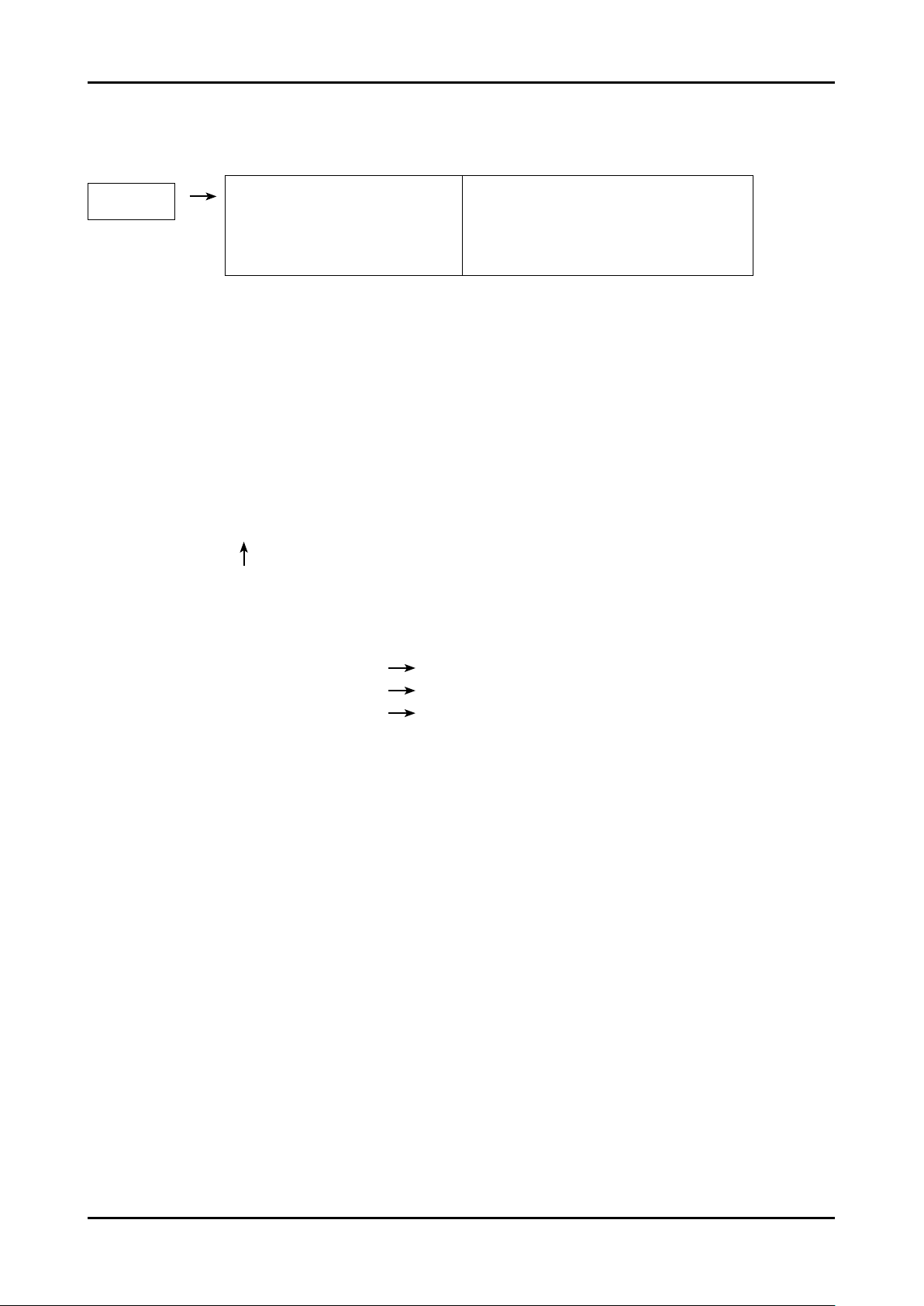
4. Troubleshooting
4-4-3 White Balance - Adjustment
(low light) (hight light)
3. W/B
Sub Bright
R offset
G offset
B offset
Sub Contrast
R gain
G gain
B gain
(W/B adjustment Condition refer next page)
4-5. White Ratio (Balance) Adjustment
1.
You can adjust the white ratio in factory mode (1:Calibration, 3:White-Balance).
2.
Since the adjustment value and the data value vary depending on the input source, you have to
adjust these in CVBS, Component 1 and HDMI 1 modes.
3.
The optimal values for each mode are congured by default. (Refer to T
It varies with Panel’s size and Specication.
- Equipment : CS-210
- Pattern: MIK K-7256 #92 “Flat W/B Pattern” as standard
- Use other equipment only after comparing the result with
that of the Master equipment.
able 1, 2)
- Set Aging time : 60min
- Calibration and Manual setting for WB adjustment.
HDMI : Calibration at #24 Chessboard Pattern Manual adjustment #92 pattern (720p)
COMP: Calibration at #24 Chessboard Pattern
CVBS: Calibration at #24 Chessboard Pattern
- If nishing in HDMI mode, adjustment coordinate is almost same in A
- White Balance Manual Adjustment
Manual adjustment at #92 pattern (720p)
Manual adjustment at #92 pattern (NTSC)
V/COMP mode.
4-30
Page 43
x y Y(L) T(K) + MPCD
CVBS
(NTSC)
COMP
(720P)
HDMI
(720P)
H/L 272 287
L/L 272 287
H/L 272 287
L/L 272 287
H/L 272 287
L/L 272 287
- Adjustment Specication
White Balance : High light (±2), Low light (±3)
Luminance : High light (Don’t care), Low light (±0.2 Ft/L)
4-6. Servicing Information
Adjustment Coordinate
-
(Sub_CT:132)
12.0cd/m
(Sub_CT:132)
12.0cd/m
(Sub_CT:132)
12.0cd/m
2
(3.5 Ft)
-
2
(3.5 Ft)
-
2
(3.5 Ft)
4. Troubleshooting
+10)
11,000 (
+10)
11,000 (
+10)
11,000 (
+10)
11,000 (
+10)
11,000 (
+10)
11,000 (
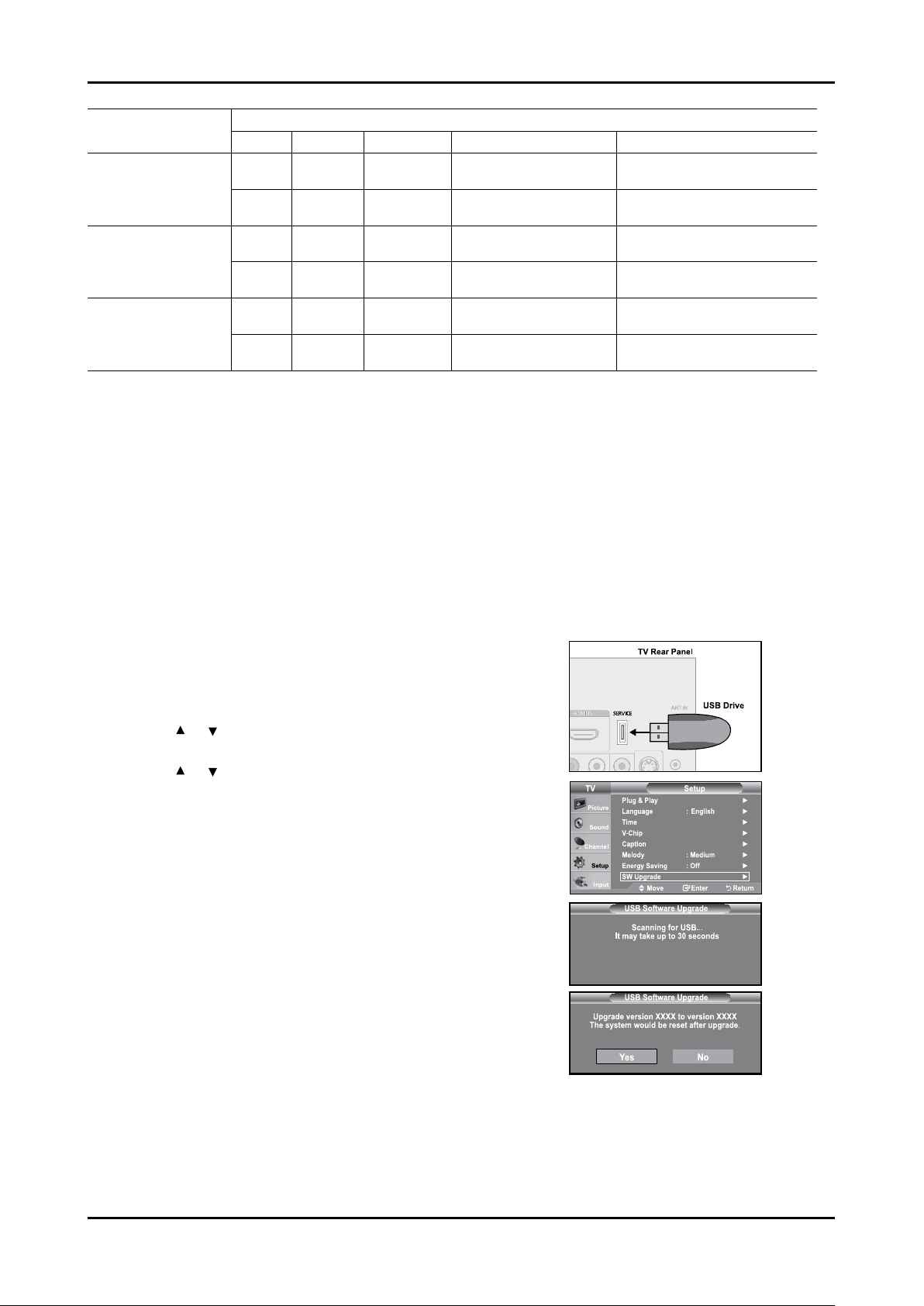
4-6-1 USB Download Method
Samsung may offer upgrades for TV’s rmware in the future. Please contact the Samsung call center at
1-800-SAMSUNG (7267864) to receive information about downloading upgrades and using a USB drive.
Upgrades will be possible by connecting a USB drive to the USB port located on located on the back of your TV.
1.
Insert a USB drive containing the rmware upgrade into the
SERVICE port on the rear of the TV.
Software can not be upgraded through the LAN connection.
2.
Press the MENU button to display the menu.
Press the
ENTER button.
3.
Press the
ENTER button.
Press the ENTER button.
4.
The message “Scanning for USB... It may take up to 30
seconds.” is displayed.
The message “Upgrade version XXXX to version XXXX The
5.
system would be reset after upgrade.” is displayed.
Press the ◄ or ► to select the “Yes”, then press the ENTER
button.
Please be careful to not disconnect the power or remove the
USB drive while upgrades are being applied. The TV will turn off
and turn on automatically after completing the rmware upgrade.
Please check the rmware version after the upgrades are
complete. When software is upgraded, video and audio settings
you have made will return to their default (factory) settings.
We recommend you write down your settings so that you can
easily reset them after the upgrade.
or button to select “Setup”, then press the
or button to select “SW upgrade”, then press the
4-31
Page 44

4. Troubleshooting
Memo
4-32
Page 45
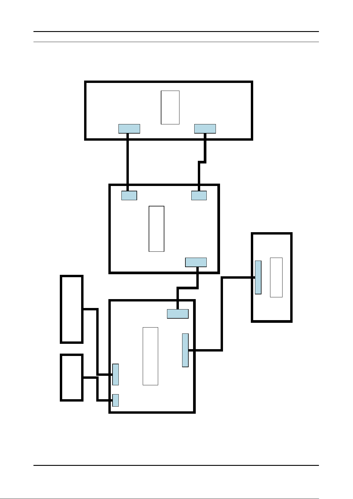
6. Wiring Diagram
Function & IR Speaker
CN301
CN303
CN2
CN401
CN201
CN301 CN701
DriverDriver
IP BoardIP Board
Main BoardMain Board
T- CONT- CON
6-1. Wiring Diagram
6. Wiring Diagram
6-1
Page 46
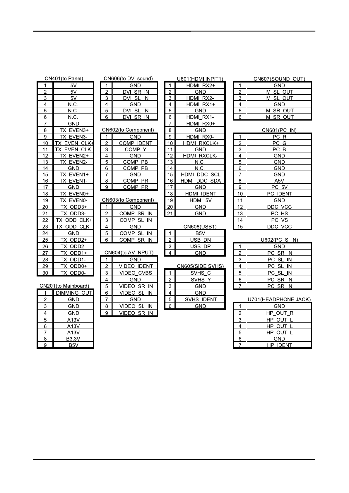
6. Wiring Diagram
6-2
Page 47
6-2. Cables
6. Wiring Diagram
Code
Photo
BP39-00028A
(19” POWER CABLE)
BN96-02854Q
(19” LVDS CABLE)
6-3
Page 48

6. Wiring Diagram
Memo
6-4
Page 49

7. Schematic Diagram
7-1. MSD2248AL Block Diagram
7. Schematic Diagram
7-1
Page 50

7. Schematic Diagram
7-2. Slim Half Tuner Block Diagram
7-2
Page 51

7-3. Internal Block Diagram of Scaler(MSD2248AL)
7. Schematic Diagram
7-3
Page 52
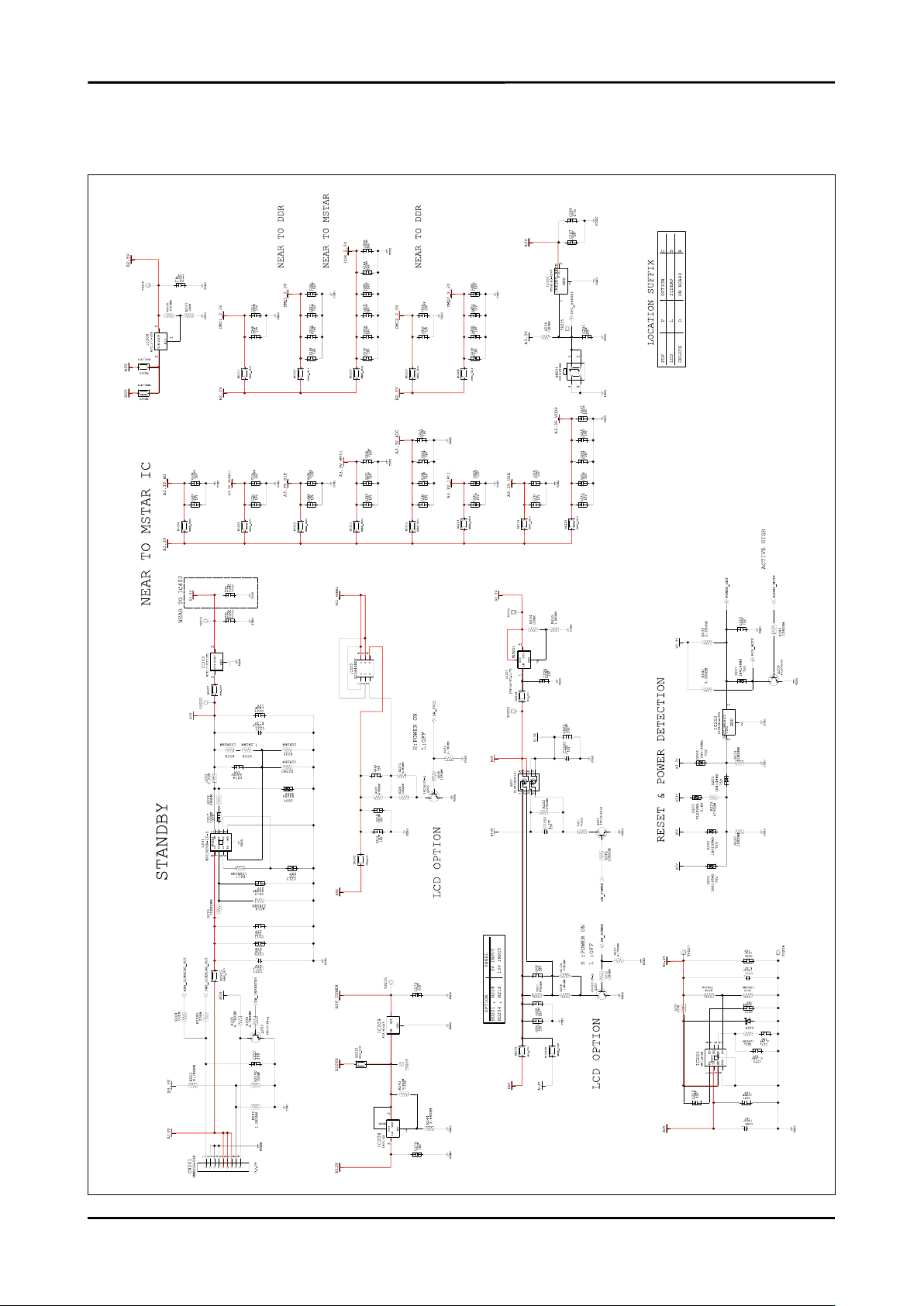
7. Schematic Diagram
7-2. Schematic Diagrams
7-2-1. MAIN POWER BLOCK
7-4
Page 53
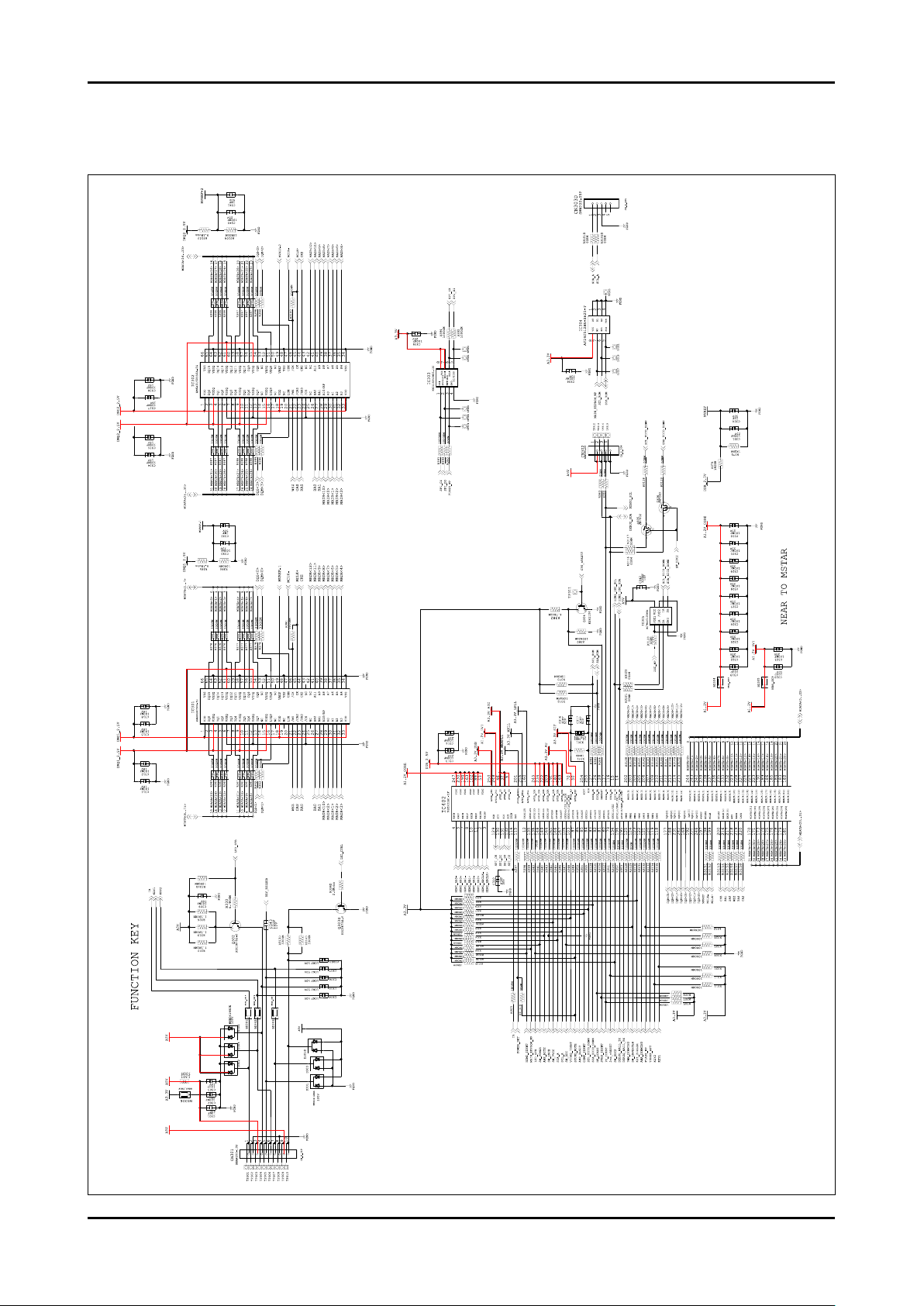
7-2-2.
7. Schematic Diagram
7-5
Page 54
7. Schematic Diagram
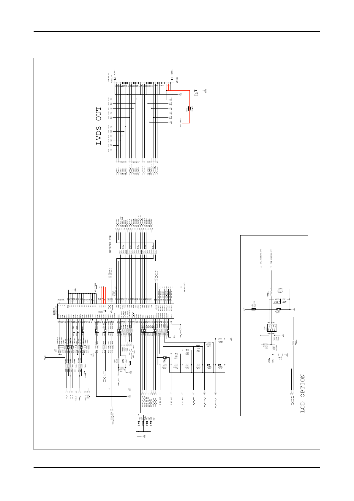
7-2-3.
7-6
Page 55
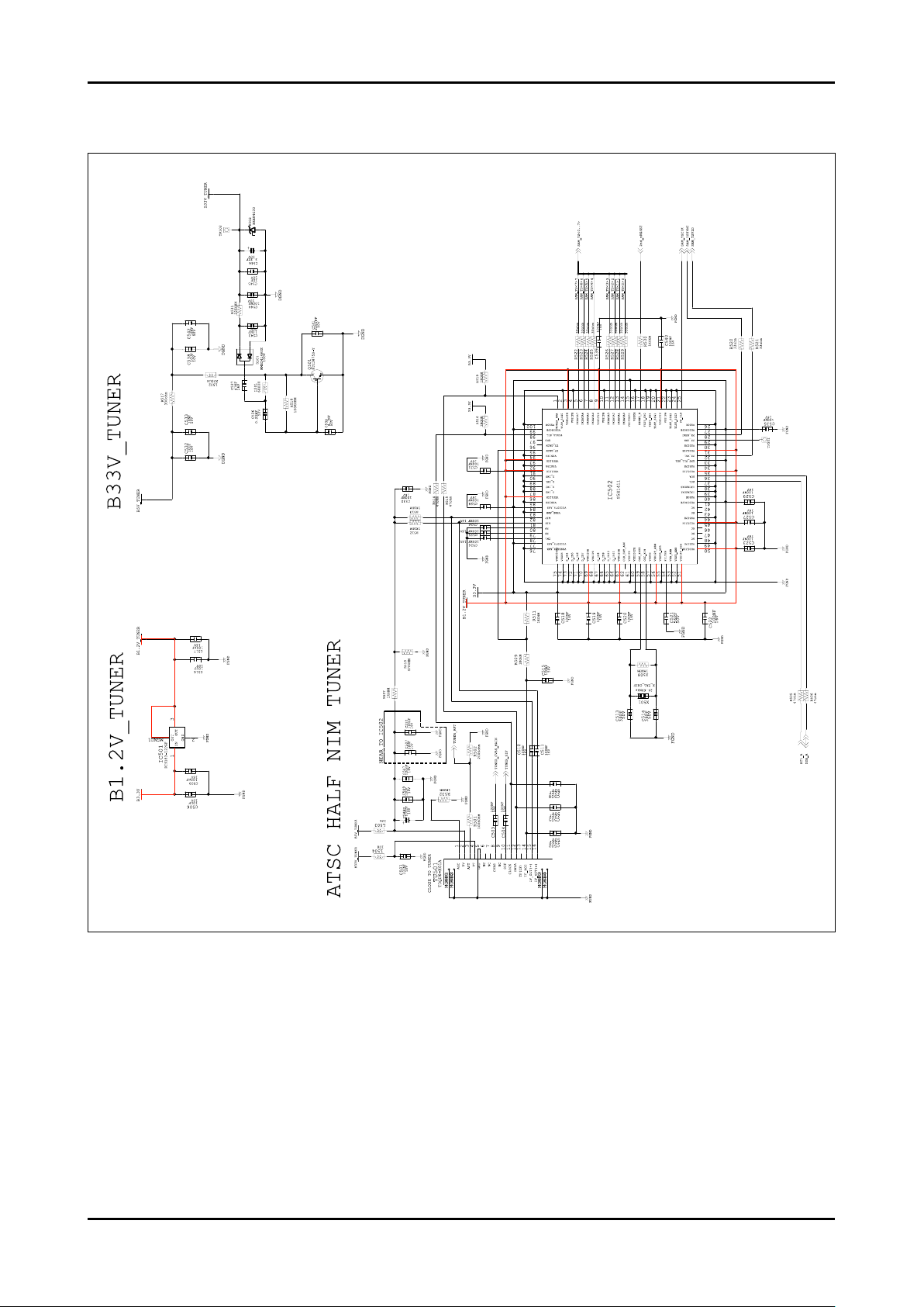
7-2-4.
7. Schematic Diagram
7-7
Page 56
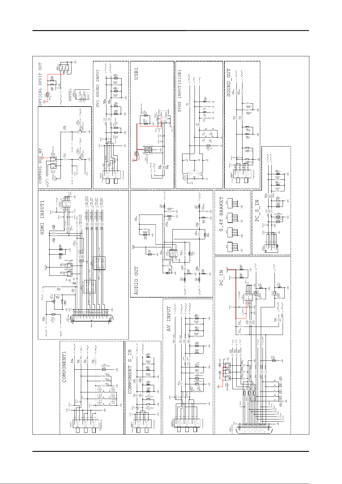
7. Schematic Diagram
7-2-5.
7-8
Page 57
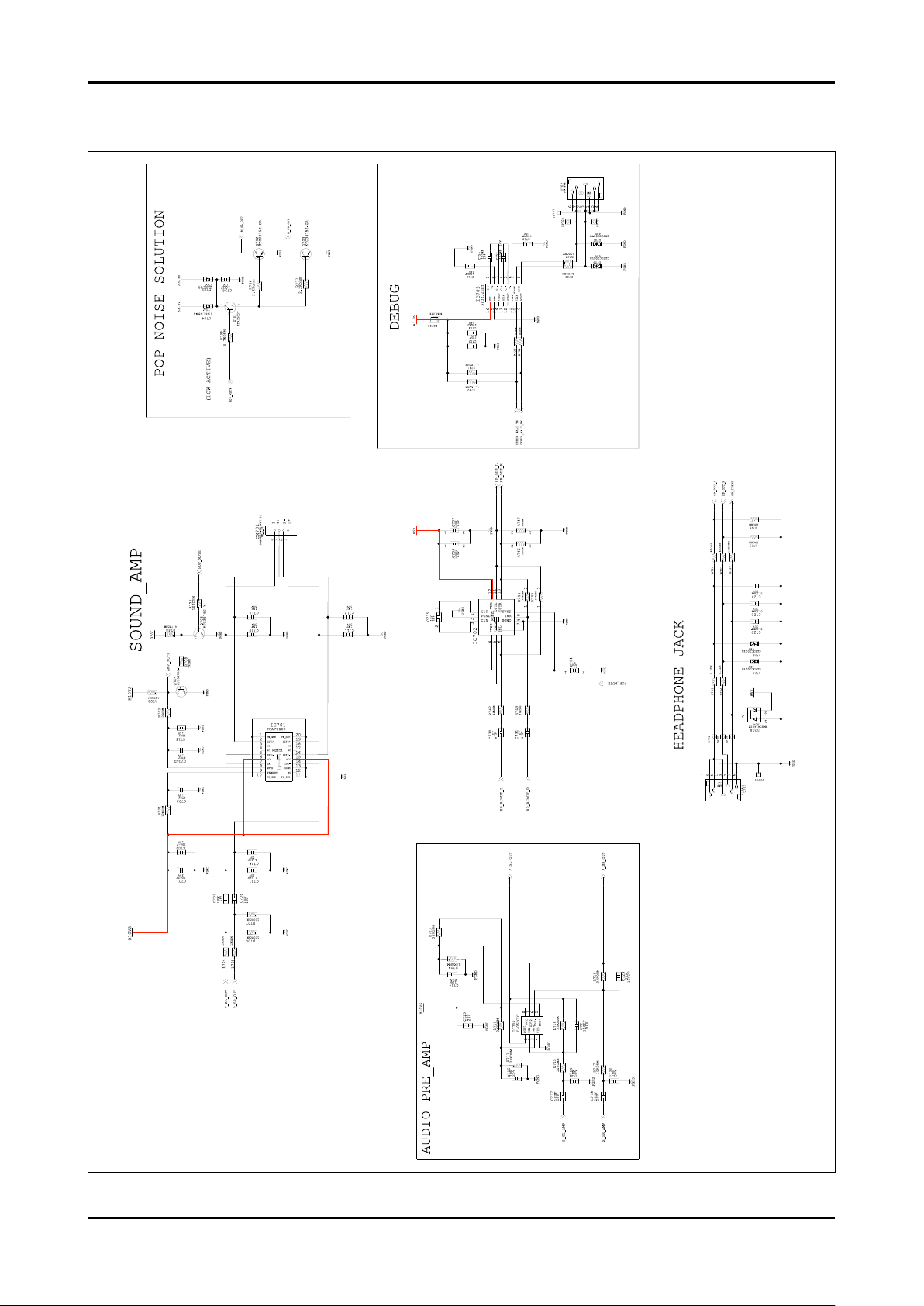
7-2-6.
7. Schematic Diagram
7-9
Page 58

7. Schematic Diagram
Memo
7-10
 Loading...