


10 Operating Instructions and Installation
10-1
10 Operating Instructions and Installation
10-1 Front
1. SOURCE
Toggles between all the available input sources
(TV, AV1, AV2, S-Video1, S-Video2, Component1,
Component2, PC, HDMI1, HDMI2). In the on-screen
menu, use this button as you use the ENTER
button on the remote control.
2. MENU
Press to see an on-screen menu of your TV's features.
If it is set to shop Mode. press and hold the "MENU"
Button on the front panel of the product for three seconds.
3. VOL
Press to decrease or increase the volume.
In the on-screen menu, use the VOL buttons as
you use the and buttons on the remote control.
4. CH
Press to change channels.
In the on-screen menu, use the CH buttons
as you use the and buttons on the remote control.
5. SPEAKERS
6. (POWER)
Press to turn the TV on and off.
7. POWER INDICATOR
Blinks and turns off when the power is on and lights
up in stand-by mode.
8. REMOTE CONTROL SENSOR
Aim the remote control towards this spot on the TV.
- The product color and shape may vary depending on the model.
10-2 LNS4096D/LNS4696D/LNS5296D Connection Panel
10 Operating Instructions and Installation
10-2
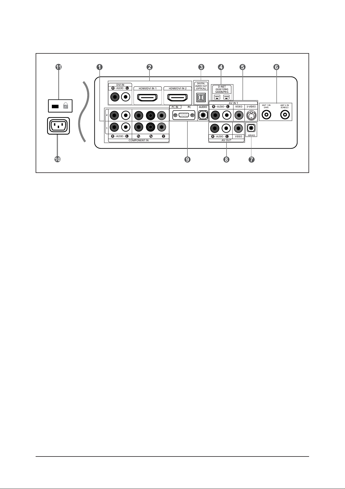
1. COMPONENT IN 1,2
Connect Component video/audio.
2. DVI IN, HDMI/DVI IN 1,2
onnect to the HDMI jack of a device with an HDMI
output.
Use the HDMI/DVI terminal for DVI connection to an
external device with a DVI output. You should use
the DVI to HDMI cable or DVI-HDMI adapter (DVI to
HDMI) for video connection, and the DVI-IN
'R-AUDIO-L' terminal for audio.
- HDMI/DVI IN terminal does not support PC.
- No sound connection is needed for an HDMI to
HDMI connection. Sound connection is only
needed for HDMI to DVI.
3. DIGITAL AUDIO OUT (OPTICAL)
Connect to a Digital Audio component.
4. D-Net (IEEE1394) S400 MPEG
Connect to external IEEE1394 digital products such
as digital VCRs and camcorders. Two jacks are
provided for this purpose, which allow for a high
degree of flexibility for connecting your D-Net
controlled system.
5. AV IN 1
Video and audio inputs for external devices, such as
a camcorder or VCR.
S-VIDEO
Connect an S-Video signal from a camcorder or
VCR.
6. ANT 1 IN(AIR) / ANT 2 IN(CABLE)
Connect to an antenna or cable TV system.
7. SERVICE
Connectors for service only.
8. AV OUT
Connect to the audio input jacks on your Amplifier/
Home theater.
9. PC IN
Connect to the video and audio output jacks on your
PC.
10.POWER INPUT
Connect the supplied power cord.
11.KENSINGTON LOCK
The Kensington lock (optional) is a device used to
physically fix the system when used in a public
place.
If you want to use a locking device, contact the
dealer where you purchased the TV.
- The place of the Kensington Lock may be different
depending on its model.
10 Operating Instructions and Installation
10-3
10-3 LNS4095D Connection Panel
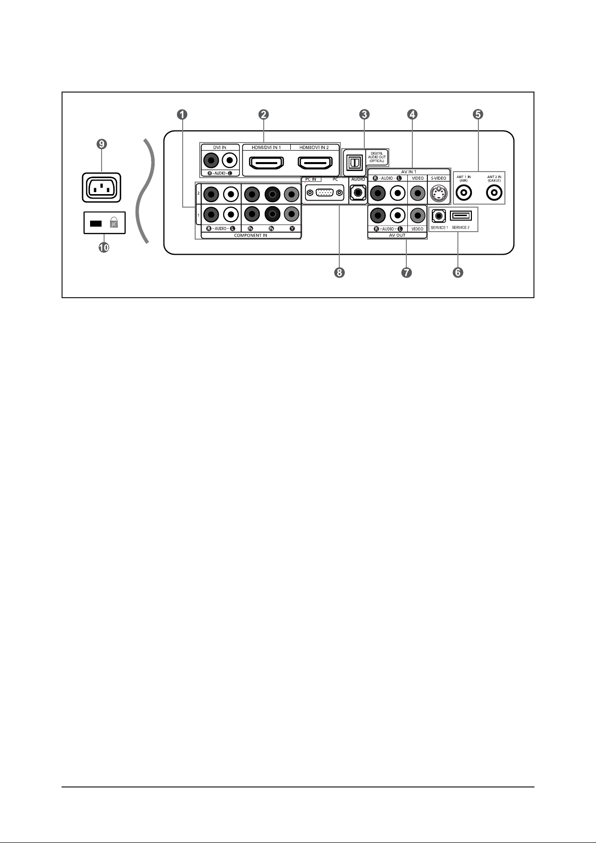
1. COMPONENT IN 1,2
Connect Component video/audio.
2. DVI IN, HDMI/DVI IN 1,2
onnect to the HDMI jack of a device with an HDMI
output.
Use the HDMI/DVI terminal for DVI connection to an
external device with a DVI output. You should use
the DVI to HDMI cable or DVI-HDMI adapter (DVI to
HDMI) for video connection, and the DVI-IN
'R-AUDIO-L' terminal for audio.
- HDMI/DVI IN terminal does not support PC.
- No sound connection is needed for an HDMI to
HDMI connection. Sound connection is only
needed for HDMI to DVI.
3. DIGITAL AUDIO OUT (OPTICAL)
Connect to a Digital Audio component.
4. AV IN 1
Video and audio inputs for external devices, such as
a camcorder or VCR.
S-VIDEO
Connect an S-Video signal from a camcorder or
VCR.
5. ANT 1 IN/ANT 2 IN
Connect to an antenna or cable TV system.
6. SERVICE 1/SERVICE 2
Connectors for service only.
7. AV OUT
Connect to the audio input jacks on your Amplifier/
Home theater.
8. PC IN
Connect to the video and audio output jacks on your
PC.
9. POWER INPUT
Connect the supplied power cord.
10.KENSINGTON LOCK
The Kensington lock (optional) is a device used to
physically fix the system when used in a public
place.
If you want to use a locking device, contact the
dealer where you purchased the TV.
- The place of the Kensington Lock may be different
depending on its model.
10 Operating Instructions and Installation
10-4
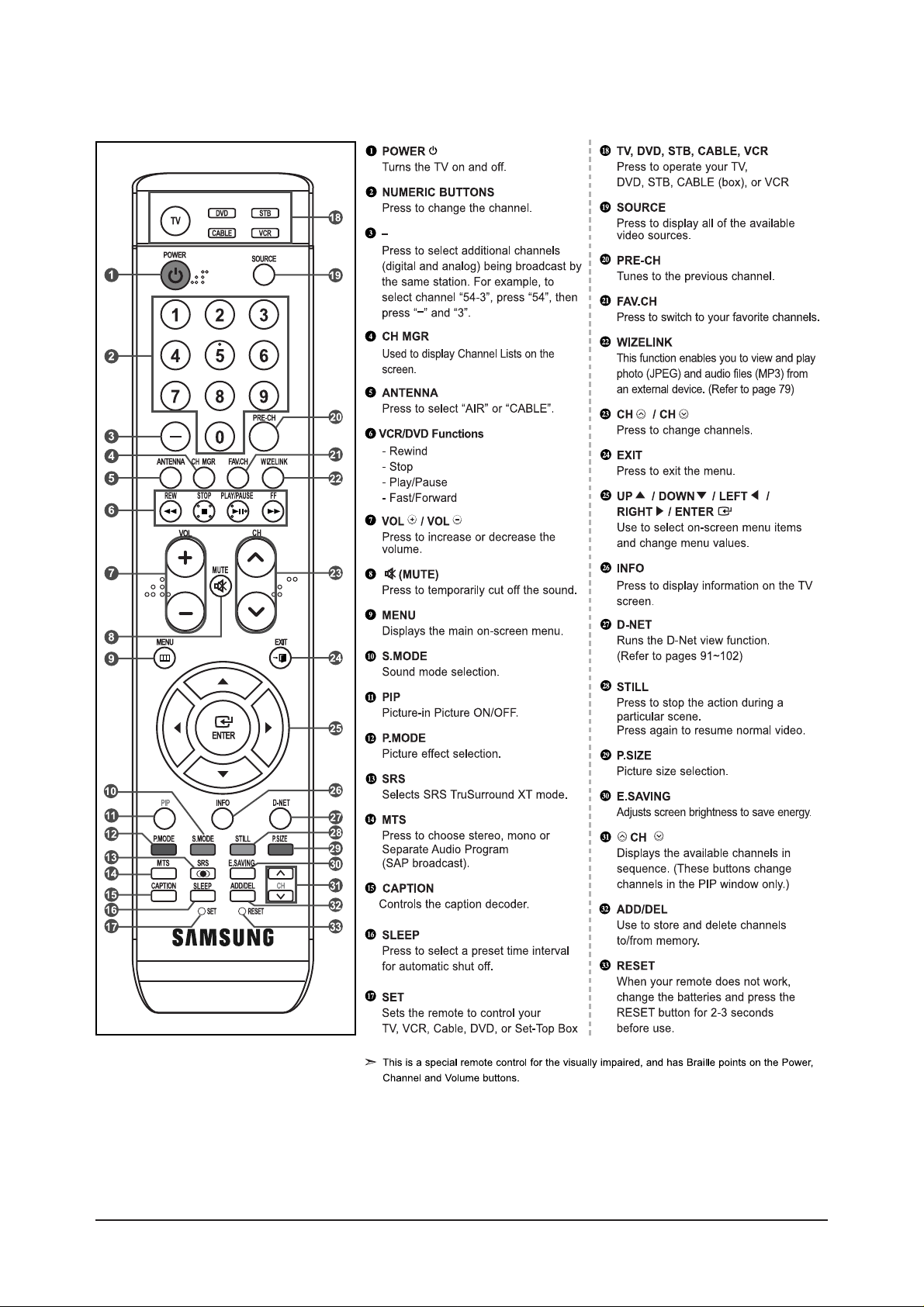
10-4 LNS4096D/LNS4696D/LNS5296D Remote Control

10 Operating Instructions and Installation
10-5
10-5 LNS4095D Remote Control

10 Operating Instructions and Installation
10-6
Memo
 Loading...