

Samsung LN22A450C1D, LN19A451, LN19A450C1D, LN22A450 User Manual
1-800-SAMSUNG (7267864)
Samsung Electronics America, Inc.
105 Challenger Road Ridgefield Park, NJ 07660-0511
Samsung Electronics Canada Inc., Customer Service
55 Standish Court Mississauga, Ontario L5R 4B2
Call center hours of operation (Mon-Sun 9AM-12AM EST).
To register this product please visit
www.samsung.com/global/register.
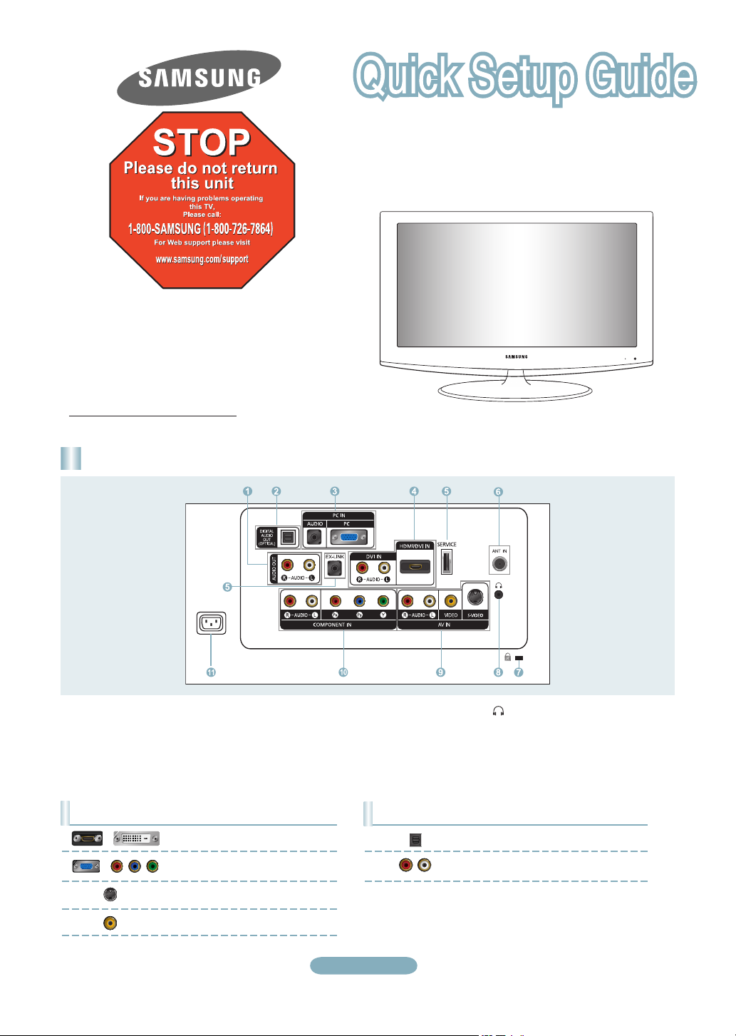
Rear Panel / Side Panel Jacks
LN19A450C1D/LN19A451C1D/
LN22A450C1D/LN22A451C1D
1 AUDIO OUT
2 DIGITAL AUDIO OUT (OPTICAL)
3 PC IN [PC] / [AUDIO]
4 DVI IN[R-AUDIO-L]
/ HDMI/DVI IN
5 SERVICE, EX-LINK
6 ANT IN
7 KENSINGTON LOCK
Video Input Performance Comparison
/
/
HDMI/DVI
PC/COMPONENT
S-VIDEO
VIDEO
Best
Better
Good
Normal
8 HEADPHONE
9 AV IN / S-VIDEO
0 COMPONENT IN
! POWER INPUT
Audio Output Performance Comparison
OPTICAL (Digital)
AUDIO (Analog)
English-1
Best
Normal
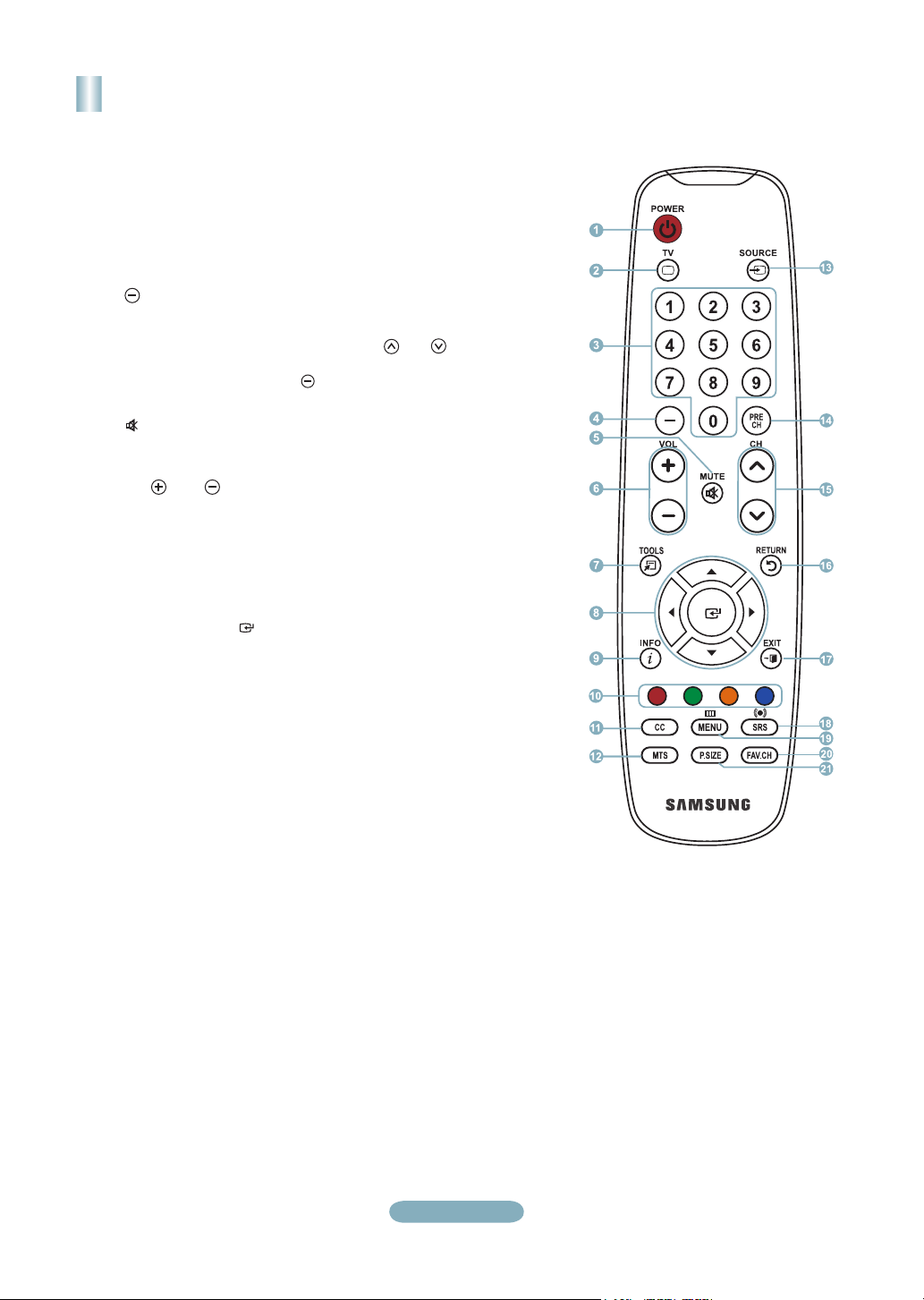
Remote Control
See “Remote Control” in the owner’s instructions for details.
1
POWER
Turns the TV on and off.
2
TV
Selects the TV mode directly.
3
NUMERIC BUTTONS
Press to change the channel.
4
Press to select additional
channels(digital and analog) being
broadcast by the same station.
For example, to select channel
“54-3”, press “54”, then press “ ”
and “3”.
5 (
MUTE)
Press to temporarily cut off the
sound.
6
VOL / VOL
Press to increase or decrease
the volume.
7 TOOLS
Use to quickly select frequently
used functions.
8 UP▲ / DOWN▼ / LEFT◄ /
RIGHT► / ENTER
Use to select on-screen menu
items and change menu values.
9 INFO
Press to display information on
the TV screen.
0
COLOR BUTTONS
Use these buttons in the
Channel list, etc.
!
CC
Controls the caption decoder.
@ MTS
Press to choose stereo, mono
or Separate Audio Program
(SAP broadcast).
#
SOURCE
Press to display and select the
available video sources.
$
PRE CH
Tunes to the previous channel.
% CH / CH
Press to change channels.
^
RETURN
Returns to the previous menu.
& EXIT
Press to exit the menu.
*
SRS
Selects SRS TruSurround XT
mode.
(
MENU
Displays the main on-screen
menu.
) FAV.CH
Press to switch to your favorite
channels.
a P.SIZE
Picture size selection.
English-2
Connections
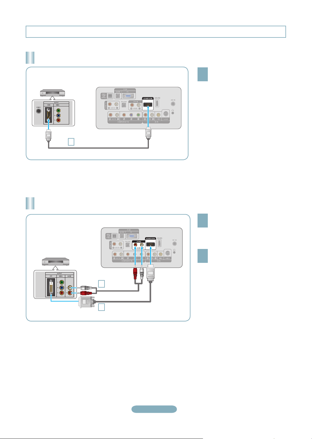
Connecting a DVD Player or Cable Box/Satellite receiver (Set-Top Box) via HDMI
Connect an HDMI Cable between
DVD Player or Cable Box/
Satellite receiver
(Set-Top Box)
HDMI Cable (Not supplied)
1
Each DVD Player or Cable Box/Satellite receiver (Set-Top Box) has a different
➣
back panel configuration.
TV Rear Panel
the HDMI/DVI IN jack on the TV
1
and the HDMI jack on the DVD
Player or Cable Box/Satellite
receiver (Set-Top Box).
What is HDMI?
•
HDMI(High-Definition Multimedia
Interface), is an interface that enables the
transmission of digital audio and video
signals using a single cable.
•
The difference between HDMI and DVI
is that the HDMI device is smaller in
size and has the HDCP (High Bandwidth
Digital Copy Protection) coding feature
installed.
Connecting a DVD Player or Cable Box/Satellite receiver (Set-Top Box) via DVI
Connect a DVI to HDMI Cable or
DVI-HDMI Adapter between the
1
HDMI/DVI IN jack on the TV and the
DVI jack on the DVD Player or Cable
Box/Satellite receiver (Set-Top Box).
Connect Audio Cables between the
DVI IN [R-AUDIO-L] jack on the TV
2
and the DVD Player or Cable Box/
Satellite receiver (Set-Top Box).
DVD Player or Cable Box/
Satellite receiver (Set-Top Box)
TV Rear Panel
Audio Cable
2
(Not supplied)
DVI to HDMI Cable (Not supplied)
1
Each DVD Player or Cable Box/Satellite receiver (Set-Top Box) has a different
➣
back panel configuration.
When connecting a DVD Player or Cable Box/Satellite receiver (Set-Top Box),
➣
match the color of the connection terminal to the cable.
When using an HDMI/DVI cable connection, you must use the HDMI/DVI IN
➣
jack.
English-3
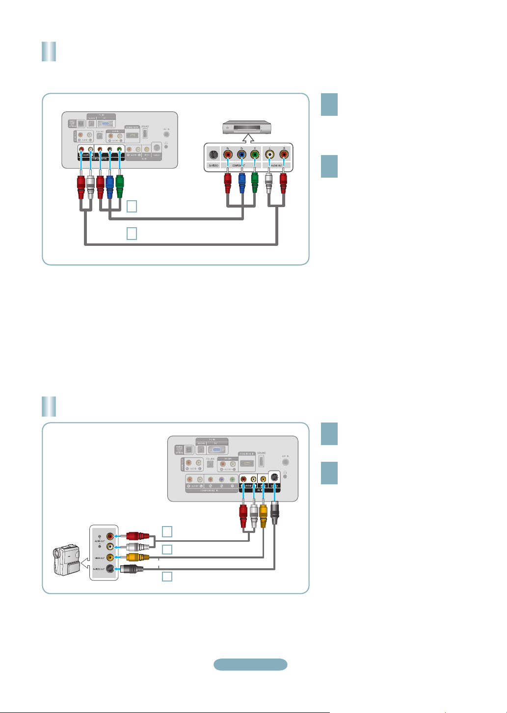
Connecting a DVD Player or Cable Box/Satellite receiver (Set-Top Box)
via Component cables
TV Rear Panel
1
2
DVD Player or Cable Box /
Satellite receiver (Set-Top Box)
Component Cable (Not supplied)
Audio Cable (Not supplied)
Connect a Component Cable between
the COMPONENT IN [Y, PB, PR] jacks
1
on the TV and the COMPONENT [Y,
PB, PR] jacks on the DVD Player or
Cable Box/Satellite receiver (Set-Top
Box).
Connect Audio Cables between the
COMPONENT IN [R-AUDIO-L] jacks
2
on the TV and the AUDIO OUT jacks
on the DVD Player or Cable Box/
Satellite receiver (Set-Top Box).
Component video separates the video
➣
into Y (Luminance (brightness)), Pb
(Blue) and Pr (Red) for enhanced video
quality.
Be sure to match the component video
and audio connections.
For example, if connecting
a Component video cable to
COMPONENT IN, connect the audio
cable to COMPONENT IN also.
Each DVD Player or Cable Box/
➣
Satellite receiver (Set-Top Box) has a
different back panel configuration.
When connecting a DVD Player or
➣
Cable Box/Satellite receiver (Set-Top
Box), match the color of the connection
terminal to the cable.
Connecting a Camcorder
Audio cable (Not supplied)
Camcoder
2
Video Cable (Not supplied)
1
or
S-Video Cable (Not supplied)
1
TV Side Panel
English-4
Connect a Video Cable (or S-Video
Cable) between the AV IN [VIDEO]
1
(or S-VIDEO) jack on the TV and the
VIDEO OUT jack on the camcorder.
Connect Audio Cables between the
AV IN [R-AUDIO-L] jacks on the TV
2
and the AUDIO OUT jacks on the
camcorder.
Each Camcorder has a different back
➣
panel configuration.
When connecting a Camcorder, match
➣
the color of the connection terminal to
the cable.
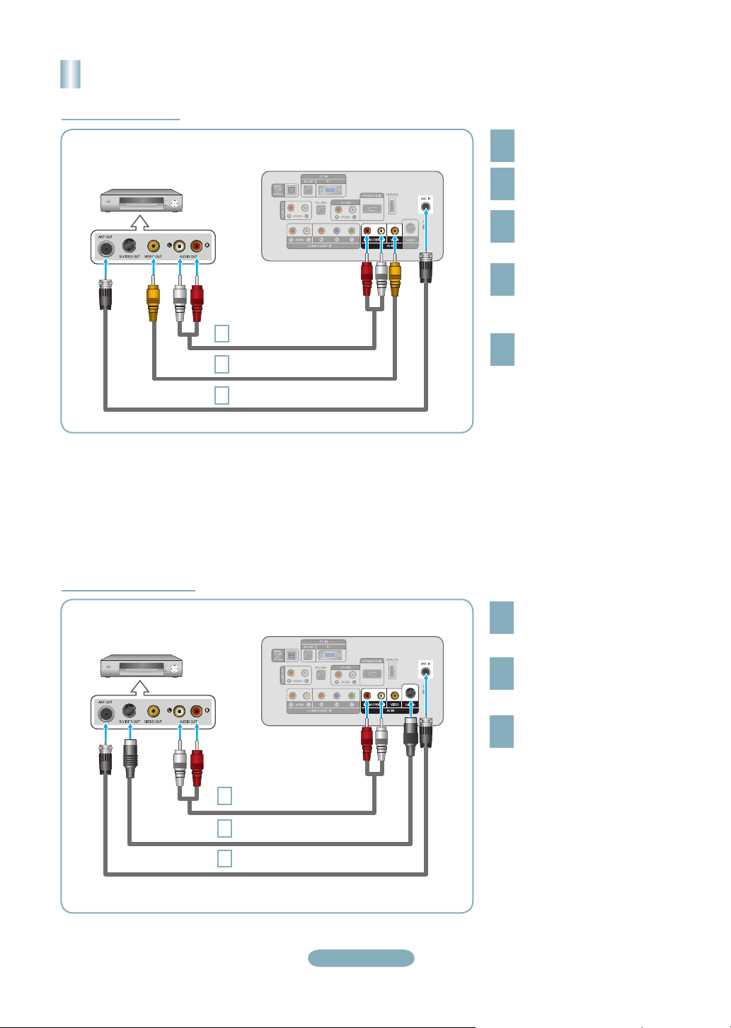
Connecting a VCR
Video Connection
TV Rear Panel
VCR Rear Panel
Audio Cable (Not supplied)
5
Video Cable (Not supplied)
4
RF Cable
3
Follow the instructions in “Viewing a VCR or Camcorder Tape” to view your VCR tape.
Each VCR has a different back panel configuration.
➣
When connecting a VCR, match the color of the connection terminal to the cable.
➣
(Not supplied)
Unplug the cable or antenna
from the back of the TV.
1
Connect the cable or antenna
to the ANT IN terminal on the
2
back of the VCR.
Connect an RF Cable between
the ANT OUT terminal on the
3
VCR and the ANT IN terminal
on the TV.
Connect a Video Cable between
the VIDEO OUT jack on the
4
VCR and the AV IN [VIDEO] jack
on the TV.
Connect Audio Cables between
the AUDIO OUT jacks on the
5
VCR and the AV IN [R-AUDIO-L]
jacks on the TV.
If you have a “mono” (non-stereo)
➣
VCR, use a Y-connector (not
supplied) to hook up to the right
and left audio input jacks of the
TV. If your VCR is stereo, you
must connect two cables.
S-Video Connection
VCR Rear Panel
Audio Cable (Not supplied)
3
S-Video Cable (Not supplied)
2
RF Cable
1
(Not supplied)
TV Rear Panel
English-5
To begin, follow steps 1–3 in
the previous section to connect
1
the antenna or cable to your
VCR and your TV.
Connect an S-Video Cable
between the S-VIDEO OUT jack
2
on the VCR and the AV IN
[S-VIDEO] jack on the TV.
Connect Audio Cables between
the AUDIO OUT jacks on the
3
VCR and the AV IN [R-AUDIO-L]
jacks on the TV.
An S-Video cable may be included
with a VCR. (If not, check your local
electronics store.)
Each VCR has a different back
➣
panel configuration.
When connecting a VCR, match
➣
the color of the connection
terminal to the cable.
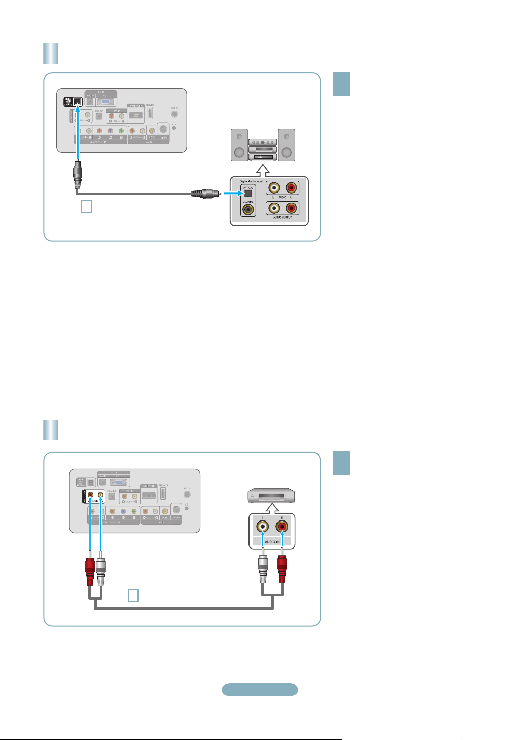
Connecting a Digital Audio System
TV Rear Panel
Optical Cable (Not supplied)
1
Digital Audio System
Connect an Optical Cable between
the “DIGITAL AUDIO OUT
1
(OPTICAL)” jacks on the TV and
the Digital Audio Input jacks on the
Digital Audio System.
When a Digital Audio System is
connected to the “DIGITAL AUDIO
OUT (OPTICAL)” jack: Decrease
the volume of the TV and adjust
the volume level with the system’s
volume control.
5.1CH audio is possible when the TV
➣
is connected to an external device
supporting 5.1CH.
Each Digital Audio System has a
➣
different back panel configuration.
When the receiver (home theater) is
➣
set to On, you can hear sound output
from the TV’s Optical jack. When the TV
is displaying a DTV(air) signal, the TV
will send out 5.1 channel sound to the
Home theater receiver. When the source
is a digital component such as a DVD
and is connected to the TV via HDMI,
only 2 channel sound will be heard from
the Home Theater receiver. If you want
to hear 5.1 channel audio, connect the
DIGITAL AUDIO OUT (OPTICAL) jack
on the DVD player or Cable/Satellite
Box directly to an Amplifier or Home
Theater, not the TV.
Connecting an Amplifier/DVD Home Theater
TV Rear Panel
Audio Cable (Not supplied)
1
Amplifier/DVD Home Theater
English-6
Connect Audio Cables between the
AUDIO OUT [R-AUDIO-L] jacks on
1
the TV and AUDIO IN [R-AUDIO-L]
jacks on the Amplifier/DVD Home
Theater.
When an audio amplifier is
connected to the "AUDIO OUT
[R-AUDIO-L]" jacks: Decrease the
volume of the TV and adjust the
volume level with the Amplifier’s
volume control.
Each Amplifier/DVD Home Theater has
➣
a different back panel configuration.
When connecting an Amplifier/DVD
➣
Home Theater, match the color of the
connection terminal to the cable.
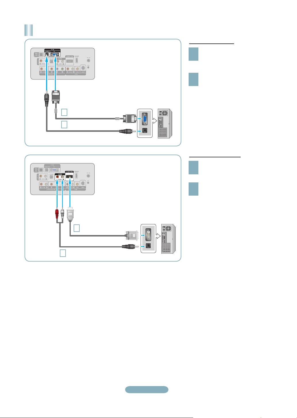
Connecting a PC
TV Rear Panel
D-Sub Cable (Not supplied)
1
PC Audio Cable (Not supplied)
2
PC
Using the D-Sub Cable
Connect a D-Sub Cable between
PC IN [PC] connector on the TV
1
and the PC output connector on
your computer.
Connect a PC Audio Cable
between the PC IN [AUDIO] jack
2
on the TV and the Audio Out jack of
the sound card on your computer.
TV Rear Panel
3.5 mm Stereo mini-plug/2RCA Cable (Not supplied)
2
HDMI/DVI Cable (Not supplied)
1
PC
Using the HDMI/DVI Cable
Connect a HDMI/DVI cable
between the
1
the TV and the PC output jack on
your computer.
Connect a 3.5 mm Stereo mini-plug/
2RCA Cable between the DVI IN
2
[R-AUDIO-L] jack on the TV and the
Audio Out jack of the sound card on
your computer.
➣
Each PC has a different back panel
configuration.
When connecting a PC, match the
➣
color of the connection terminal to the
cable.
When using an HDMI/DVI cable
➣
connection, you must use the
HDMI/DVI IN
HDMI/DVI IN
jack.
jack on
English-7
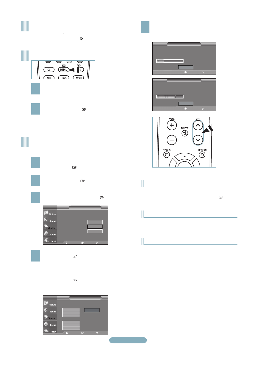
Turning the TV On and Off
Press the POWER button on the remote control.
You can also use the POWER button on the TV.
Viewing the Menus
With the power on, press the MENU button.
The main menu appears on the screen.
1
The menu’s left side has icons: Picture, Sound,
Channel, Setup, Input.
Press the ▲ or ▼ button to select one of the icons.
Then press the ENTER
2
icon’s sub-menu. Press the EXIT button to exit.
The on-screen menus disappear from the
➣
button to access the
screen after about one minute.
Storing Channels in Memory
(Automatic Method)
Press the MENU button to display the menu.
Press the ▲ or ▼ button to select “Channel”, then
1
press the ENTER button.
The TV begins memorizing all available stations.
After all the available channels are stored, it start to
5
remove scrambled channels.
Press the EXIT button to exit.
Auto Program
Plug & Play
Auto Program in Progress.
DTV Cable : -- Cable : 11
Enter Return
Removing scrambled channel.
Enter Return
Auto Program
Stop
Auto Program
Plug & Play
Auto Program
Stop
Cable 24
11 %
DTV Cable 55
80 %
Press the ▲ or ▼ button to select “Auto Program”,
then press the ENTER button.
2
Press the ▲ or ▼ button to select the antenna
connection, then press the ENTER button.
3
TV
Selects the antenna to execute the Auto
Program function.
Auto Program
Air
Cable
Auto
Move Enter Return
Move Enter Return
Start
Start
Start
When selecting the Cable TV system:
Press the ENTER button to start the auto
4
program.
Press the ◄ or ► button, then press the ▲ or ▼ to
select the correct analog signal cable system source
among “STD”, “HRC”, and “IRC”.
Press the ENTER button.
If you have Digital cable TV, select the cable system
signal source for both Analog and Digital.
TV
Selects a cable signal type for your location.
Auto Program
Analog
STD
HRC
IRC
Digital
STD
HRC
IRC
Move Enter Return
Move Enter Return
Start
English-8
To Stop the Auto Program Function
Press the MENU button while the Auto Program function is
being executed. You can also press the ENTER button
to stop the setup.
Checking to see if Channels were Stored in Memory
Press the CH button. Only the channels stored in memory
will be selected (in order).
Selecting the antennas
• Air: “Air” antenna signal.
• Cable: “Cable” antenna signal.
• Auto: “Air” and “Cable” antenna signals.
 Loading...