

Page 1
SyncMaster 797MB/997MB
Page 2
Main Page On- Screen D isplay
Safety Instru ctions Troubleshooting
Notationa l Check List
Power Q & A
Installation Self- Test Featur e C heck
Clean
Oth e r
Introduction Specifications
Unpacki ng Genera l Specifications
Front PowerSaver
Rear Preset Timing Modes
Bottom
Setup Information
Connecting the Monitor Service
Installing the Monitor Driver Ter ms
Automatic Regulato ry
Manual Natur al Color
Base Ins tallation Authority
Page 3
Notational
Power
Installation
Clean
Oth e r
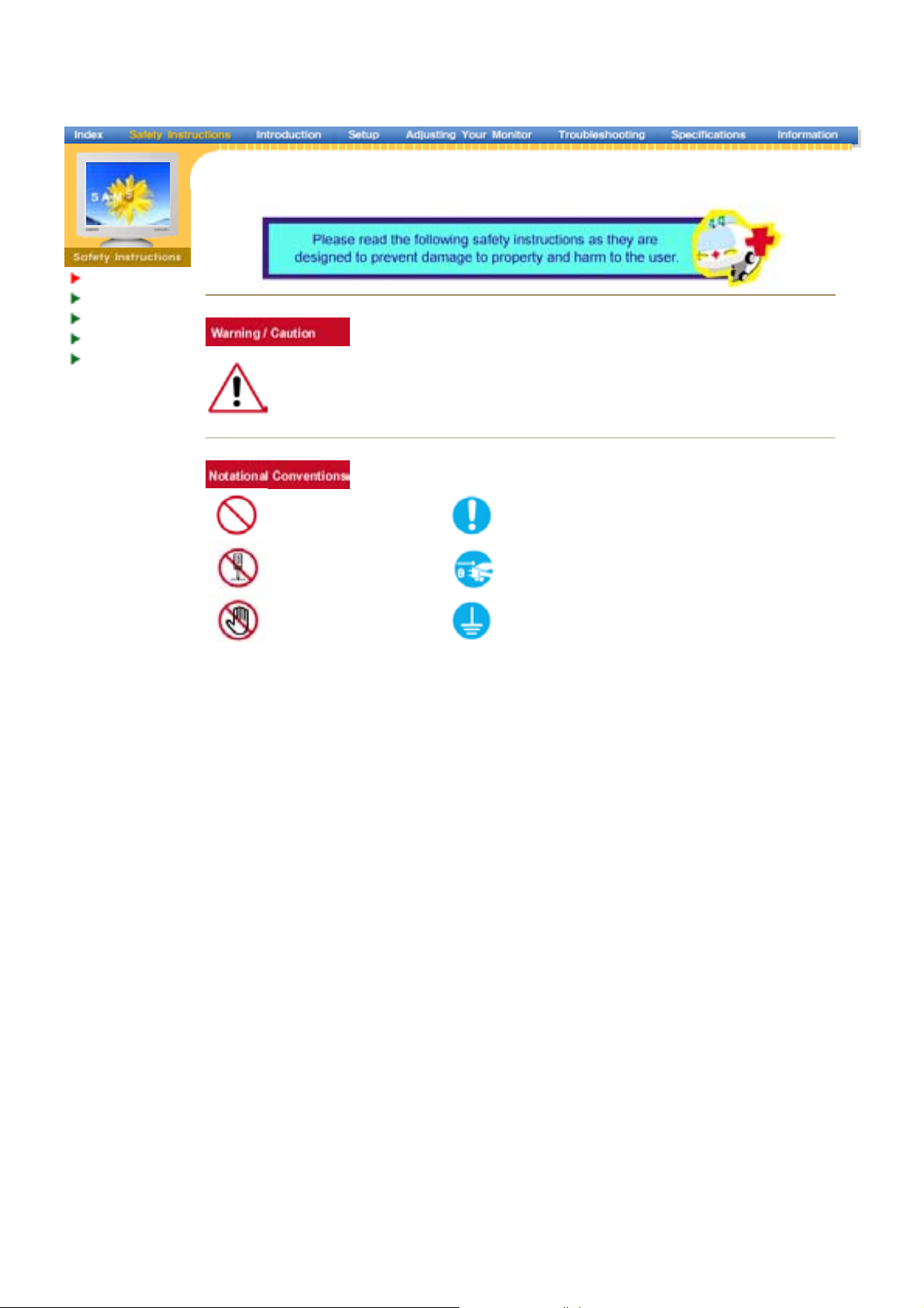
Failure to follow directions noted by this symbol could result in bodily harm or damage to
equipment.
Prohibited Important to read and understand at all times
Do not disassemble Disconnect the plug from the outlet
Do not touch Grounding to prevent an electric shock
Page 4
Notationa l
r
Powe
Installation
Clean
Oth e r
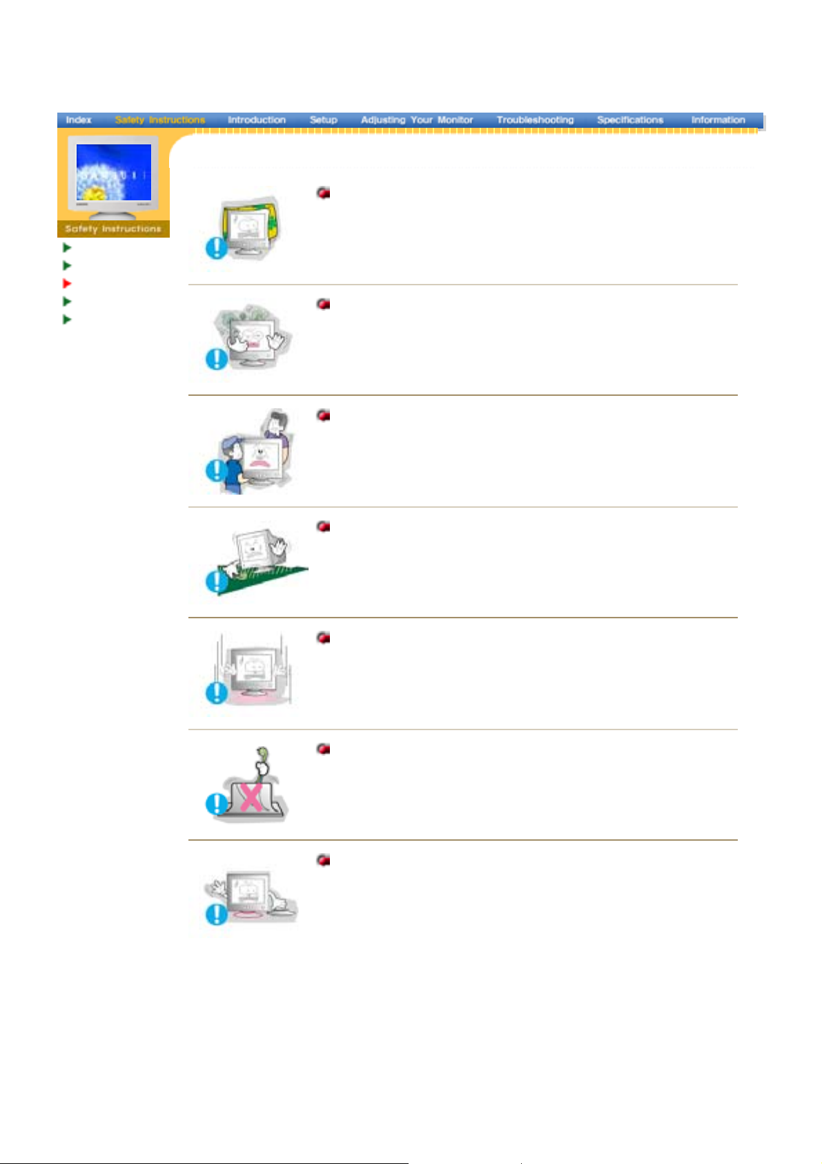
When not used for extended periods of time, set your computer to DPMS. If
using a screen saver, set it to the active screen mode.
z
If the size of your monitor is small, or if the same image is present for long
periods of time, you may see afterimages due to damage to the
fluorescent substance on the inside of the CDT.
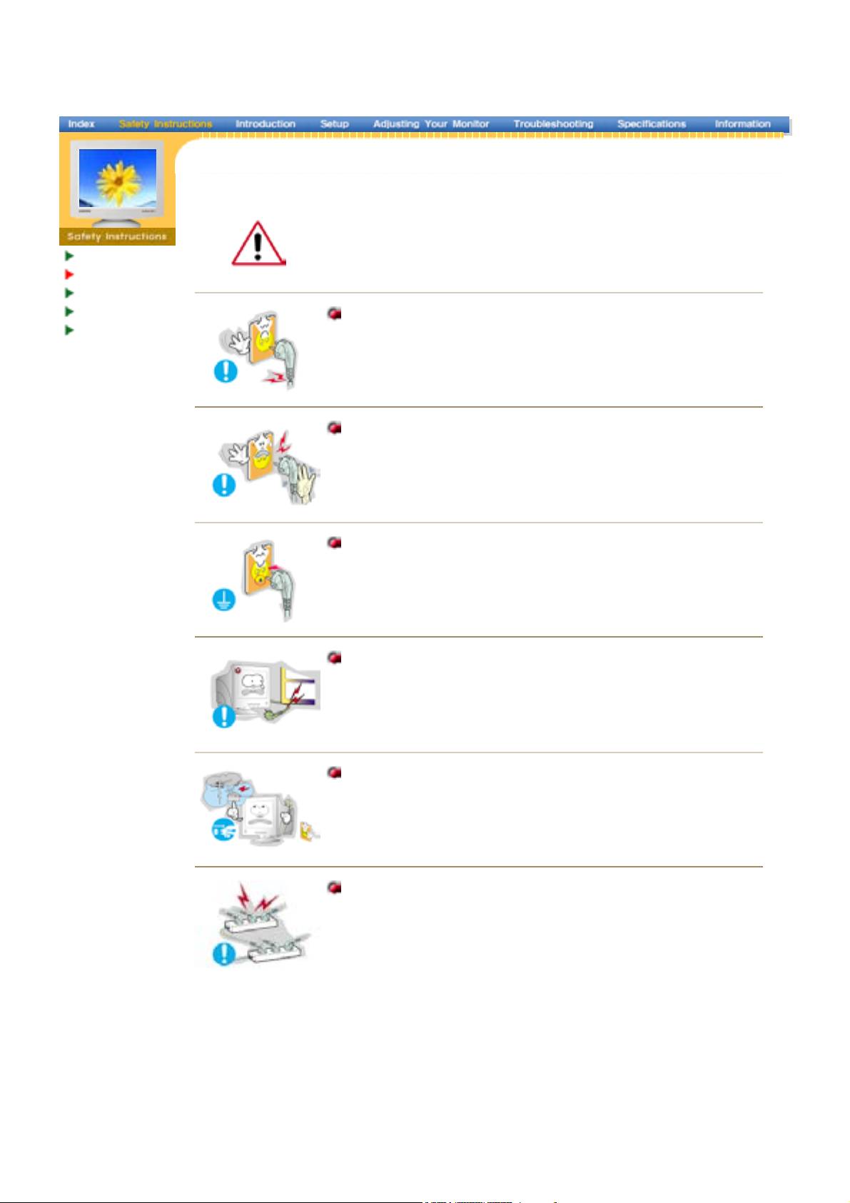
Do not use a damaged or loose plug.
z
This may cause an electric shock or fire.
Do not pul l the pl ug out by the wire nor touc h the plu g with we t
han ds.
z
This may cause an electric shock or fire.
Use only a proper ly grounded pl ug and recep tacle.
z
An improper ground may cause electric shock or equipment
damage.
Do not excessively bend the plug and wire nor place heavy objects
upon them, whic h could cause damage.
z
Failure to do so may cause an electric shock or fire.
Disconnect the plug from the outlet during storms or lightening or
if i t is not us ed for a long peri od o f ti me.
z
Failure to do so may cause an electric shock or fire.
Do not connect too many extension cords or plugs to an outlet.
z
This may cause a fire.
Page 5
Notationa l
Power
Installation
Clean
Oth e r
Do not cover the vents on the monitor cabinet.
z
Bad ventilation may cause a breakdown or fire.
Put your monitor in a location with low humidity and a minimum of
dus t.
z
An electric shock or fire could result inside the monitor.
Do not drop the monitor when moving it.
z
This may cause damage to the product or human body.
Place the monitor on a flat and stable surface.
z
The monitor can cause injury by falling.
Set down the monitor carefully.
z
It could be damaged or broken.
Do not place the monitor face down.
z
The CDT surface may be damaged.
Do not use the monitor without the monitor stand.
z
It could break down or cause a fire due to bad ventilation.
z
If the monitor must be used without the supplied stand, take steps
to insure proper ventilation.
Page 6
Notationa l
g
Power
Installation
Clean
Oth e r
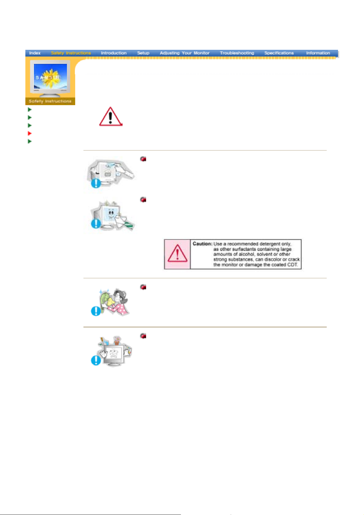
When cleaning the monitor case or the surface of the CDT, wipe with a
slightly moistened, soft fabric.
Do not clean Flat monitor with water. Use a water-diluted mild
detergent.
(Some detergents contain significant amounts of alcohol-based solvents,
which can damage (color change) or crack the monitor case. The
antiglare/anti-static surface coating on the CDT may also be affected.)
Dilute the deter
ent (1:10 ratio) with water before using.
Do not spray detergent directly on the monitor.
Use the recommended detergent with a smooth cloth.
z
You can prevent the coated CDT from being damaged or the
monitor cabinet from being dissolved, cracked or discolored.
z
You can buy a recommended detergent at any Samsung Service
Center.
If the connector between the plug and the pin is dusty or dirty,
clean it properly with a dry cloth.
z
A dirty connector can cause an electric shock or fire.
Do not set a glass of water, chemicals or any small metal objects
on the monitor.
z
This may cause damage, electric shock or a fire.
z
If a foreign substance gets into the monitor, disconnect the plug
and then contact a service center.
Page 7
Notationa l
r
Power
Installation
Clean
Othe
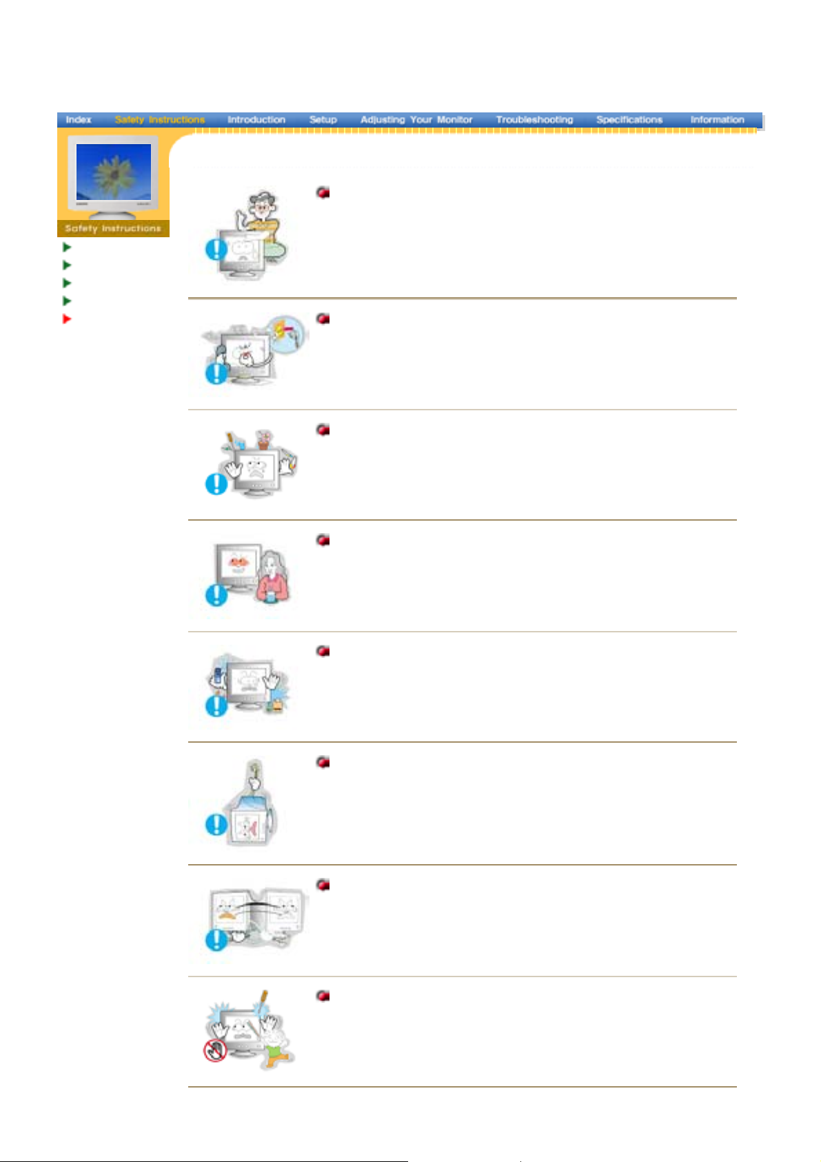
Do not remove cover(or back). No user serviceable parts inside.
z
This may cause an electric shock or a fire.
z
Refer servicing to qualified service personnel.
If your monitor does not operate normally - in particular, if there are
any unusual sounds or smells coming from it - unplug it
immediately and contact an authorized dealer or service.
z
This may cause an electric shock or a fire.
Do not place any heavy objects on the monitor.
z
This may cause an electric shock or a fire.
For each hour of looking at the monitor, you should let your eyes
rest for 5 minutes.
z
This will reduce eye fatigue.
Do not use or store inflammable substances near the monitor.
z
This may cause an explosion or fire.
Do not try to mo ve the monito r by pulling on th e wi re or th e si gn al
cable.
z
This may cause a breakdown, electric shock or a fire due to
damage to the cable.
Do not move the monitor right or left by pulling only the wire or the
signal cable.
z
This may cause a breakdown, electric shock or a fire due to
damage to the cable.
Never insert anything metallic into the monitor openings.
z
This may cause an electric shock, fire or injury.
Page 8

Keep the monitor away from any magnetic substances.
z
This may cause discoloring or distortion of the image.
Page 9
(
)
D
SyncMaster 797MB
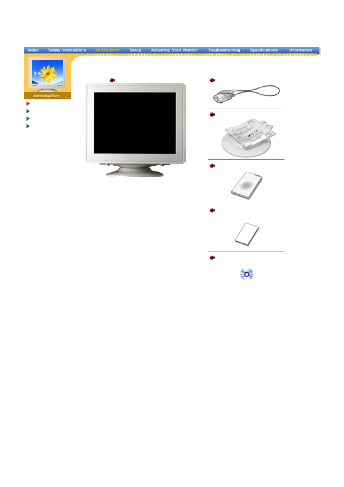
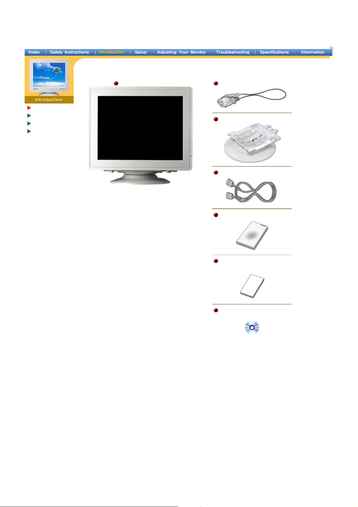
Unpacking
Front
Rear
Bottom
Monitor and Stand
(Some models include a stand attached. )
Please make sure the following items are included
with your monitor. If any items are missing,
contact your dealer .
Power Cord
Stand
Quic k Setup Guide
Warranty Card
Not available in all locations
User's Guide and
Driver Instal lati on C
Page 10
)
(
)
D
SyncMaster997MB
Unpacking
Front
Rear
Bottom
Monitor and Stand
(S ome models inc lude a stand attached. )
Please make sure the following items are included
with your monitor. If any items are missing,
contact your dealer .
Power Cord
Stand
Signal Cable (Option
Quick Setup Guide
War ranty Card
Not available in all locations
User's Guide and
Driver Instal lati on C
Page 11
Unpacki ng
p
Front
Rear
Bottom
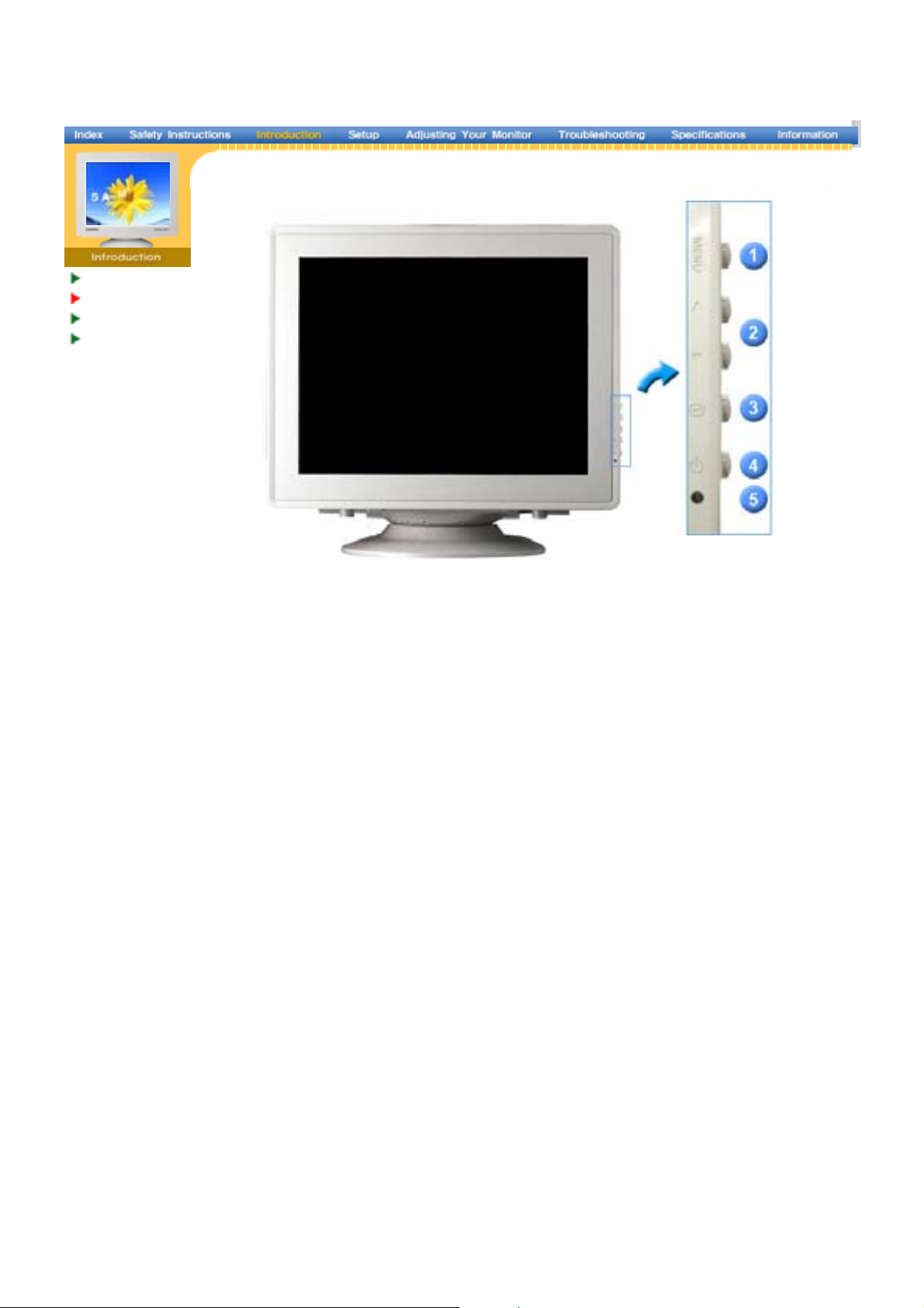
1. Menu button Opens the OSD menu. Also used to exit the OSD menu or return to the
revious menu.
2. Adjust buttons These buttons allow you to highlight and adjust items in the menu.
3. Enter button Used to select the OSD menu.
4. Power button Use this button for turn the monitor on and off.
5. Power indicator This light glows green during normal operation, and blinks green once as
the monitor saves your adjustments.
Note: See PowerSaver described in the manual for further information regarding power saving
functions. For energy conservation, turn your monitor OFF when it is not needed, or when
leaving it unattended for long periods.
Page 12
r
Genera l
(
)
,
(
)
(Op
)
BNC Connecto rs (Option)
Unpacki ng
Front
Rea
Bottom
General
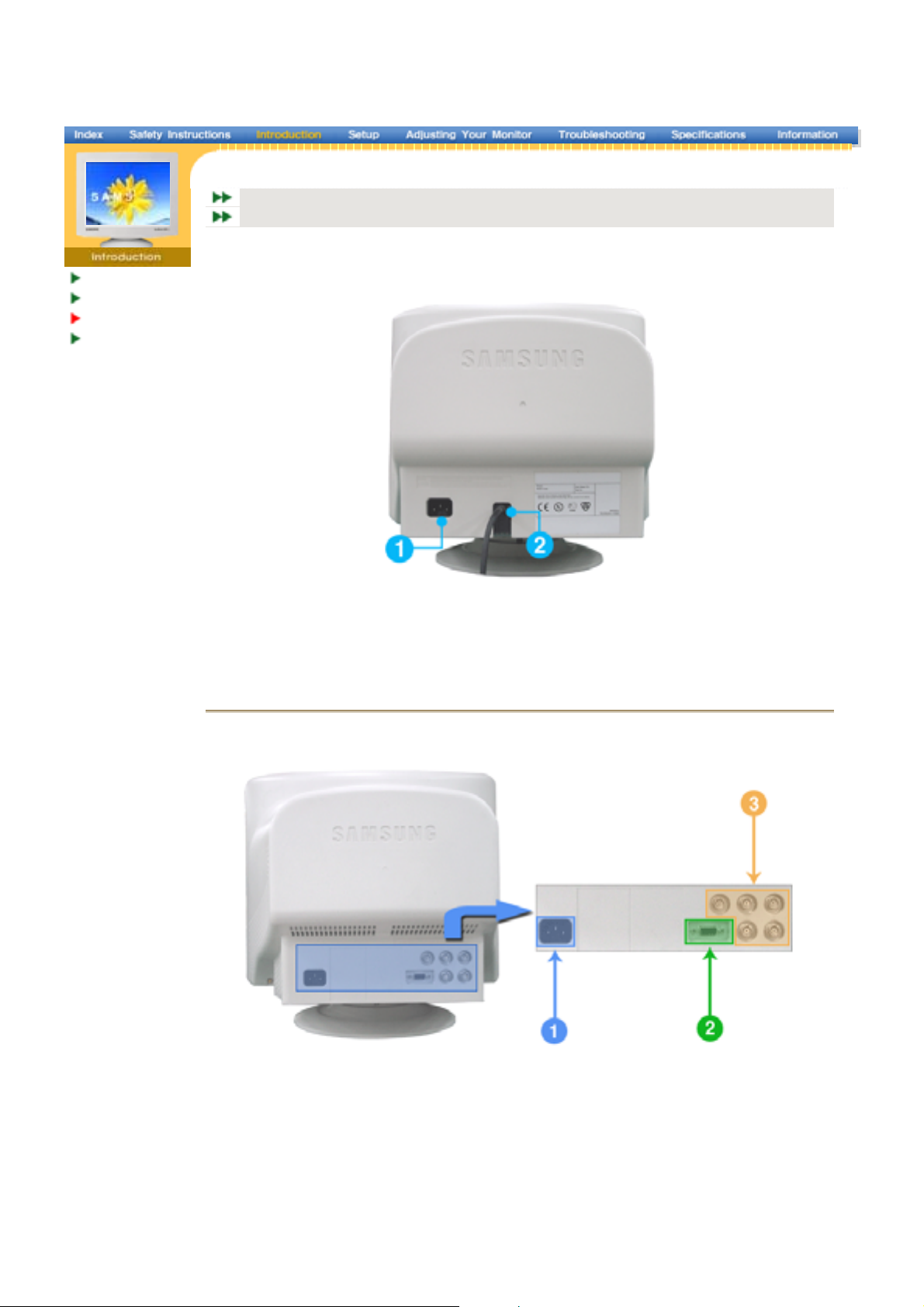
The configuration at the back of the monitor may vary from product to product.
1. Power port Connect the power cord for your monitor to the power port on the back of
the monitor.
2. Signal Cable Connect the signal cable to the video port on your computer, video board,
video card
SyncMaster 797MB/997MB
or graphics card.
BNC Connectors (Option)
SyncMaster 997MB
The configuration at the back of the monitor may vary from product to product.
1. Power port Connect the power cord for your monitor to the power port on the back of
2. Signal port Connect the signal cable to the 15-pin D-sub connector on the back of
3. BNC Connectors
tion
the monitor.
your monitor.
Connect the signal cable to the BNC signal port on the back of your
monitor.
Note: See Connecting the Monitor for further information regarding cable connections.
Page 13
Unpacki ng
,
p
Front
Rear
Bottom
1. Signal Cable Connect the signal cable to the video port on your computer, video board,
video card
or graphics card.
2. Power port Connect the power cord for your monitor to the power port on the back of
the monitor.
3. Tilt/Swivel Base You can se
arate the base from the monitor.
Page 14
r
Genera l
g
grap
p
y
)
g
grap
y
BNC Connecto rs (Option)
Connecting
the Monito
Installing the
Monitor Driver
Base Ins tallation
General
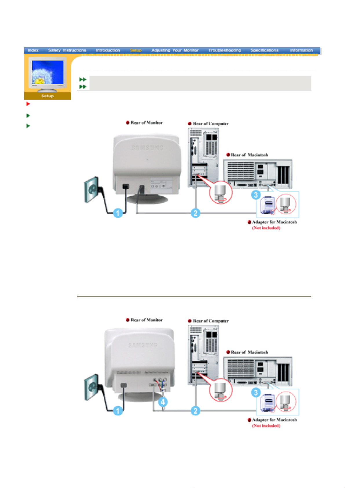
1. Connect the power cord for your monitor to the power port on the back of the monitor.
Plu
the power cord for the monitor into a nearby outlet.
2. Connect the signal cable to the video port on your computer, video board, video card, or
hics card.
3. If you are using a Macintosh computer, connect the cable to a Macintosh adapter, and set the
pins on your adapter(Adapter not included). A PC-compatible computer does not need an
ada
ter.
4. Turn on
our computer and monitor. If your monitor displays an image, installation is complete.
SyncMaster 797MB/997MB
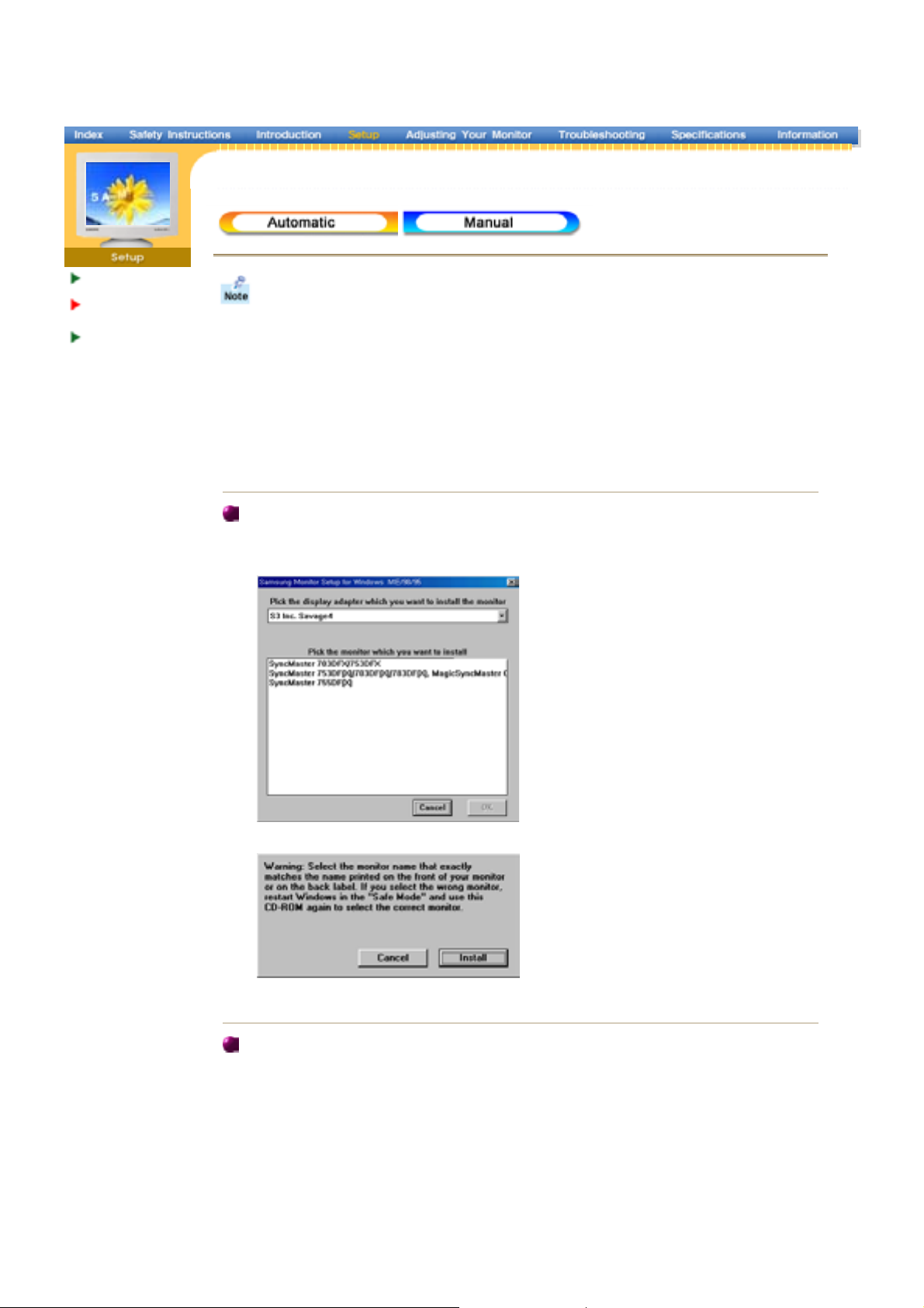
BNC Connec tors (Option
SyncMaster 997MB
1. Connect the power cord for your monitor to the power port on the back of the monitor.
Plu
the power cord for the monitor into a nearby outlet.
2. Connect the end of the signal cable to your computer's video port(video board, video card or
hics card).
ou are using a Macintosh computer, connect the cable to a Macintosh adapter, and set the
3. If
Page 15

pins on your adapter(Adapter not included). A PC-compatible computer does not need an
p
g
y
ada
ter.
4. When you use a BNC connector.
Connect the si
5. Turn on
nal cable to the BNC signalport on the back of your monitor/computer.
our computer and monitor. If your monitor displays an image, installation is complete.
Page 16
Connecting Your
r
p
)
Monitor
Installing the
Monitor Drive
Base Ins tallation
When prompted by the operating system for the monitor driver, insert the CD-ROM
inc luded wi th thi s mo nitor. Driver instal lati on i s slightly differ ent from o ne operati ng
system to another. Follow the directions as appropriate for the operating system you
have.
Prepare a blank disk and download the driver program file at the Internet web site shown
here.
z
Internet web site : http://www.samsung-monitor.com/ (WorldWide)
http://www.samsungusa.com/monitor/ (USA)
htt
://www.sec.co.kr/monitor/(Korea
http://www.samsungmonitor.com.cn/ (China)
Windows ME
1. Insert CD into the CD-ROM drive.
2. Click "Windows ME Driver".
3. Choose your monitor model in the model list, then click the "OK" button.
4. Click the "Ins tall " button in the "Warning" window.
5. Monitor driver installation is completed.
Windows X P/2000
1. Insert CD into the CD-ROM driver.
2. Click "Windows XP/2000 Driver" .
3. Choose your monitor model in the model list, then click the "OK" button.
Page 17
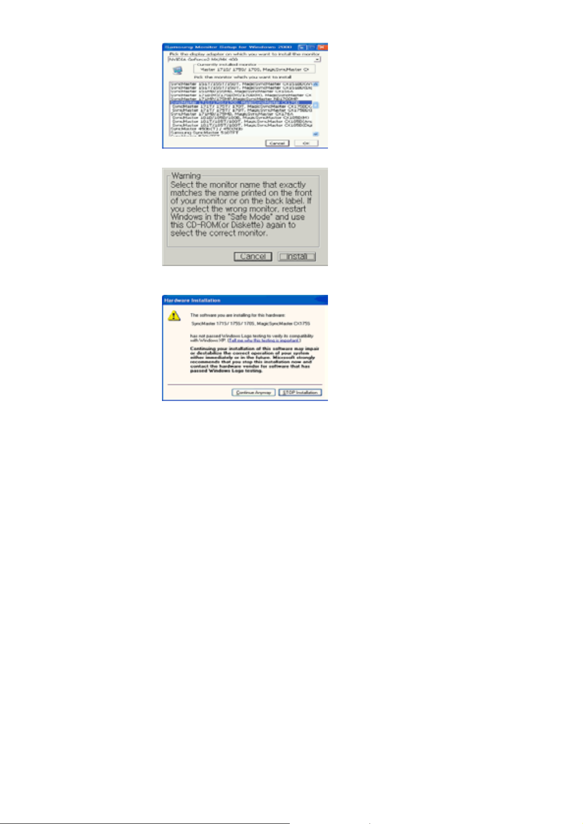
4. Click the "Ins tall " button in the "Warning" window.
5. If you can see following "Message" window, then click the "Continue Anyway" button.
Then click "OK" button.
This monitor driver is under certifying MS logo,and this installation don't damage your
system.The certified driver will be posted on Samsung Monitor Homepage
http://www.samsung-monitor.com/.
6. Monitor driver installation is completed.
Page 18
Connecting Your
r
p
)
Monitor
Installing the
Monitor Drive
Base Ins tallation
Windows XP|Windows 2000|Windows Me|Windows NT|Linux
When prompted by the operating system for the monitor driver, insert the CD-ROM
inc luded wi th thi s mo nitor. Driver instal lati on i s slightly differ ent from o ne operati ng
system to another. Follow the directions as appropriate for the operating system you
have.
Prepare a blank disk and download the driver program file at the Internet web site shown
here.
z
Internet web site : http://www.samsung-monitor.com/ (WorldWide)
htt
://www.sams ungusa.com/monitor/(US A
http://www.sec.co.kr/monitor/ (Korea)
http://www.samsungmonitor.com.cn/ (China)
Mic rosoft® Windows® XP Operating System
1. Insert CD into the CD-ROM driver.
2. Click "Start" —> "Control Panel" then click the " Appearance and Themes" Icon.
3. Click "Di splay" icon and choose the "Settings" tab then click "Advanced..".
4. Click the "Properties" button on the "Mon itor" tab and select "Dr iver " tab.
Page 19
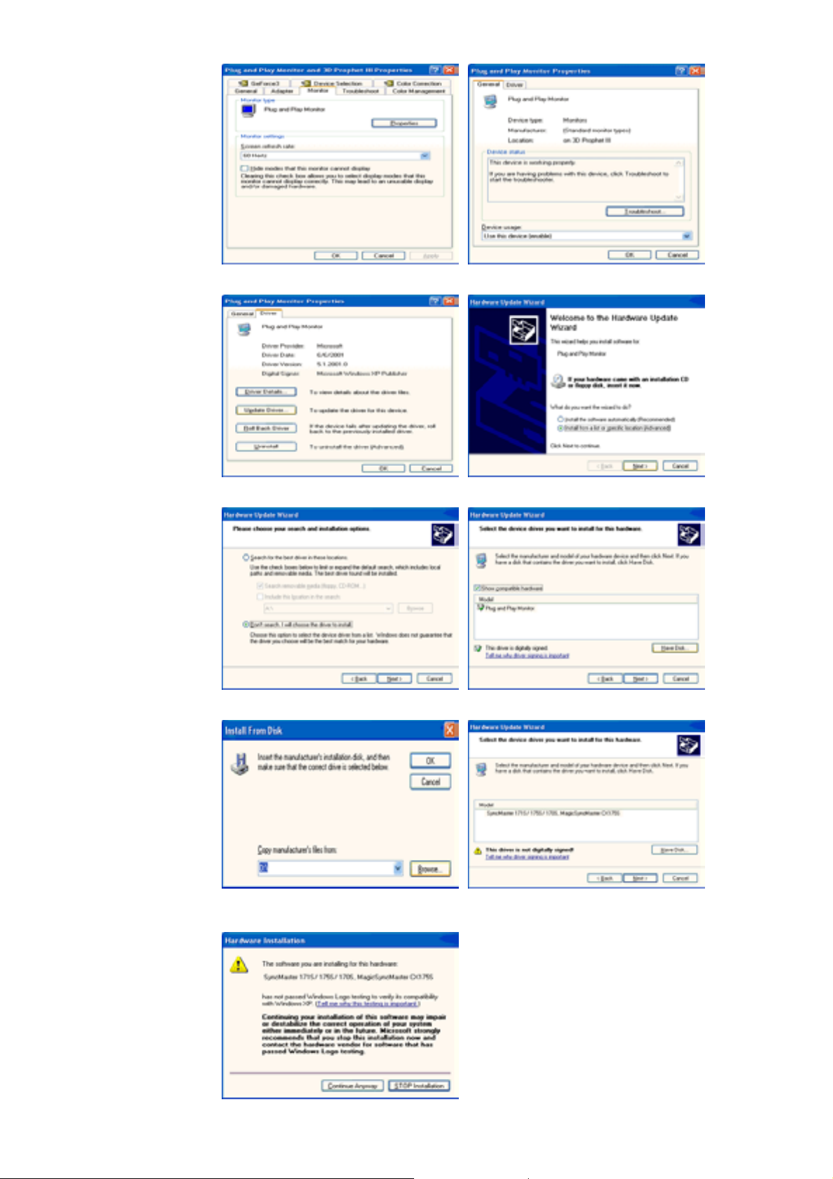
5. Click "Upd ate Driver.." and select "Install fr om a l ist or.. " then click "Next" button.
6. Select "Don't search ,I will.." then click "Next" and then click "Have disk".
7. Click the "Browse " button then choose A:(D:\Driver) and choose your monitor model in the
model list and click the "Next" button.
8. If you can see following "Message" window, then click the "Contin ue Anyway " button. Then
click "OK" button.
Page 20
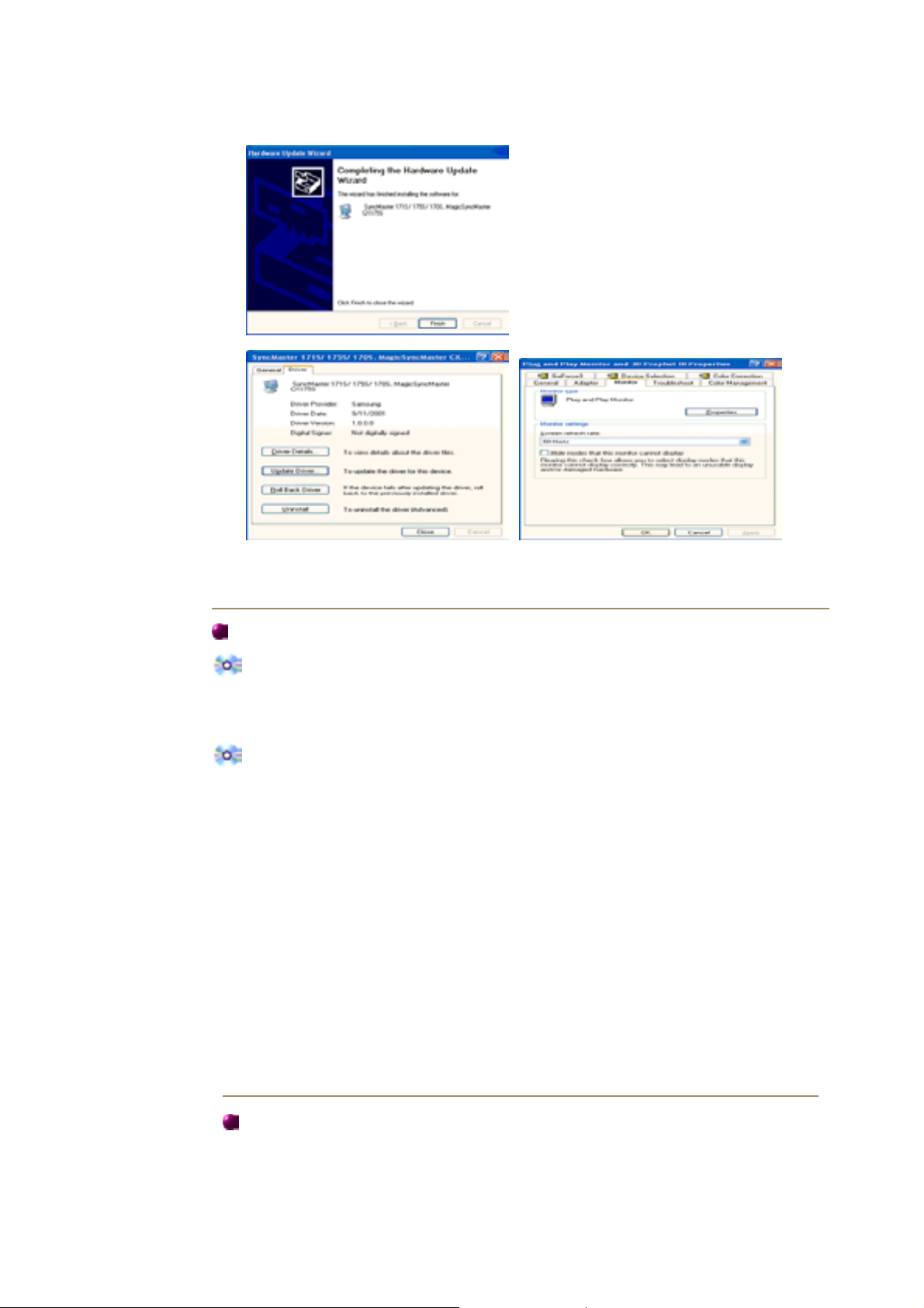
This monitor driver is under certifying MS logo,and this installation don't damage your
A
p
p
system.The certified driver will be posted on Samsung Monitor Homepage
http://www.samsung-monitor.com/.
9. Click the "Close " button then click "OK" button continually.
10. Monitor driver installation is completed.
Mic rosoft® Windows® 2000 Operating System
When you can see "Digital Signature Not Found" on your monitor, follow these steps.
1. Choose "OK" button on the "Ins ert di sk" window.
2. Click the "Browse " button on the "File Needed" window.
3. Choose A:(D:\Driver) then click the "Open" button and then click "OK" button.
How to install
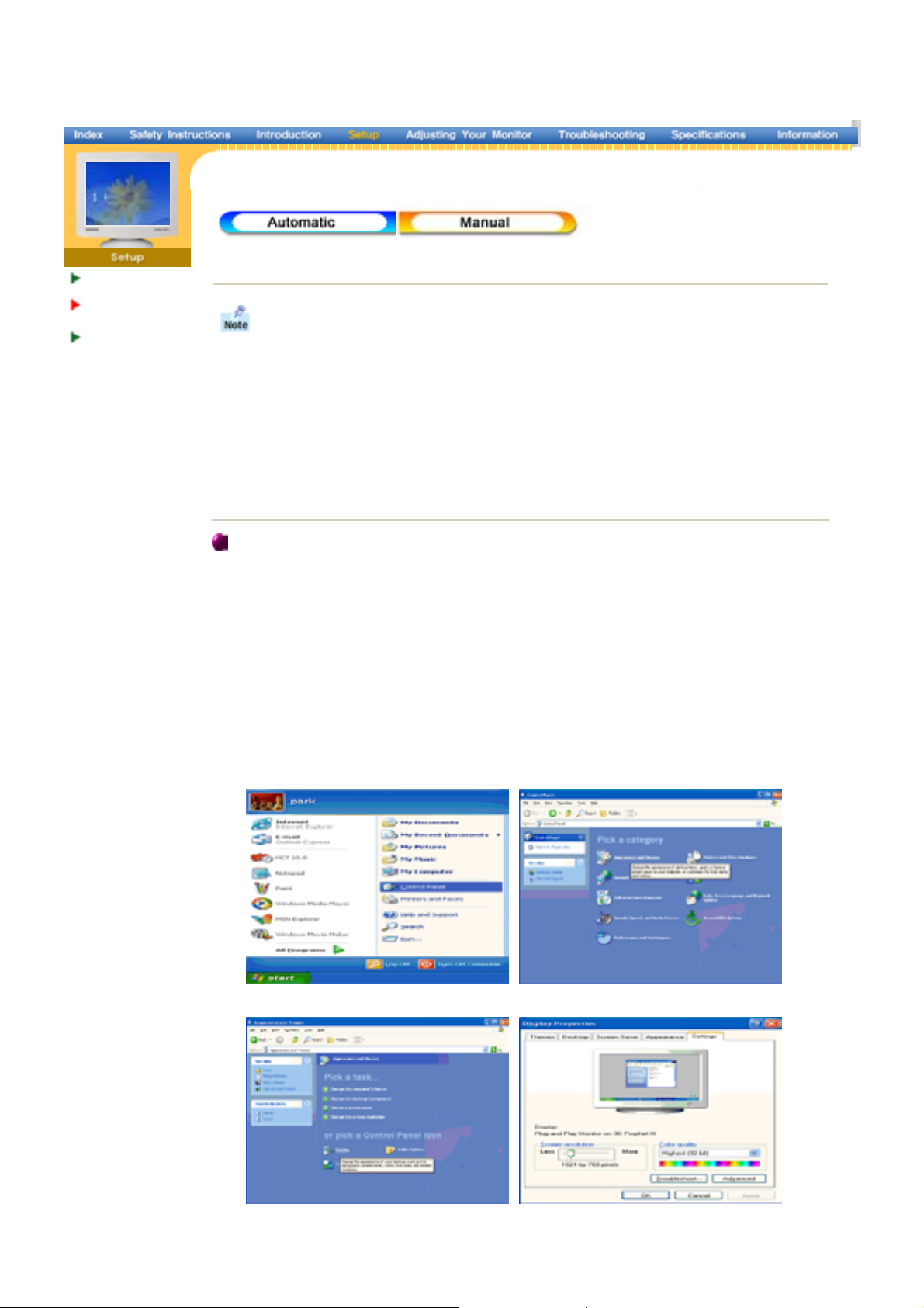
1. Click "Start" , " Setting" , "Control Panel".
2. Double click the "Display" Icon.
3. Choose the " Settings" tab and then click "Advanced..".
4. Choose "Monito r ".
Case1: If the "Properties" button is inactive, it means your monitor is properly configured.
Case2: If the "Properties" button is active, click the "Properties" button then follow next
5. Click "Driver" and then click on "Update Dr iver .. " then click on the "Next" button.
6. Choose "Display a list of the known drivers for this device so that I can choose a
specific driver" then click "Next" and then click "Have disk".
7. Click the "Browse " button then choose A:(D:\Driver).
8. Click the "Open" button, then click "OK" button.
9. Choose your monitor model and click the "Next" button then click "Next" button.
10. Click the "Finis h" button then the "Close " button.
Please sto
ste
s continually.
installation
If you can see the "Digital Signature Not Found" window then click the "Yes"button.
nd click the "Finis h" button then the "Close" button.
Mic rosoft® Windows® Millennium Operating System
1. Click "Start" , " Setting" , "Control Panel".
2. Double click "Displ ay" icon.
3. Select the " Settings" tab and click "Adv anced Properties" button.
4. Select the " Monitor" tab.
5. Click the "Cha nge" button in the "Monitor Type" area.
6. Choose "Specify the location of the driver".
Page 21

7. Choose "Display a list of all the driver in a specific location.." then click "Next" button.
s
-
8. Click the "Have Disk" button
9. Specify A:\(D:\driver) then click " OK" button.
10. Select "Show all devices" and choose the monitor that corresponds to the one you
connected to your computer and click " OK".
11. Continue choosing "Close" button and " OK" button until you close the Display Properties
dialogue box.
(You can get some other screen for warning message or others, then click the appreciate
option for your monitor.)
Mic rosoft® Windows® NT Operating System
1. Click Start, Settings, Control Panel, and then double-click Displ ay icon.
2. In Display Registration Information window, click Settings Tab and then click All Display
Modes .
3. Select a mode that you wish to use (Resolution, Number of colors and Vertical frequency)
and then click OK.
4. Click Apply button if you see the screen working normally after clicking Test. If the screen
is not normal, change to a different mode (lower mode of resolution, colors or frequency).
Note : If there is no Mode at All Di splay Modes, select the level of resolution and vertical
frequency by referring to the Preset Display Mode
Linux Operating System
To execute X-Window, you need to make the X86Config file, which is a type of system setting
file.
1. Press Enter at the first and the second screen after executing the X86Config file.
2. The third screen is for setting your mouse.
3. Set a mouse for your computer.
4. The next screen is for selecting a keyboard.
5. Set a Keyboard for your computer.
6. The next screen is for setting your monitor.
7. First of all, set a horizontal frequency for your monitor. (You can enter the frequency
directly.)
8. Set a vertical frequency for your monitor. (You can enter the frequency directly.)
9. Enter the model name of your monitor. This information will not affect the actual
execution of X-Window.
10. You have finished setting up your monitor.
Execute X
Window after setting other requested hardware.
in the user guide.
Page 22
Connecting Your
Monitor
Installing the
Monitor Driver
Base Installation
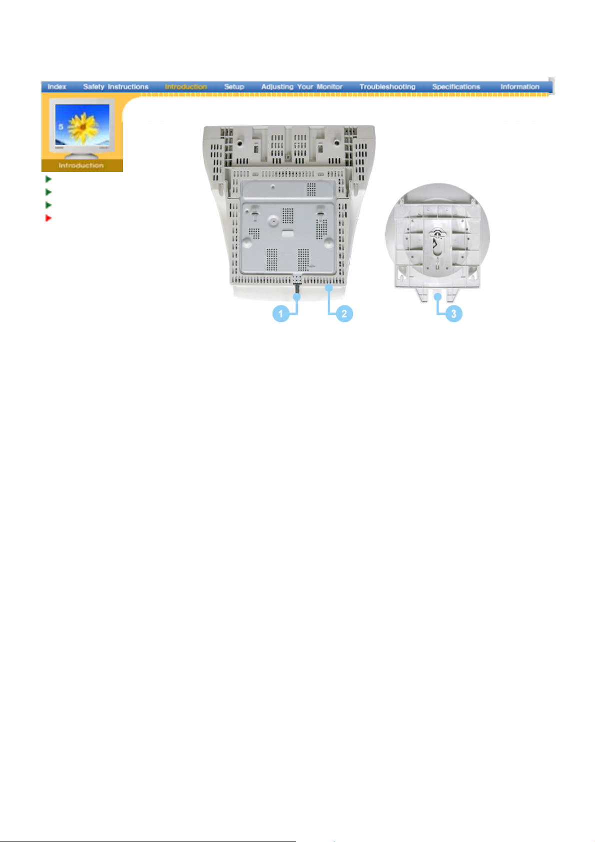
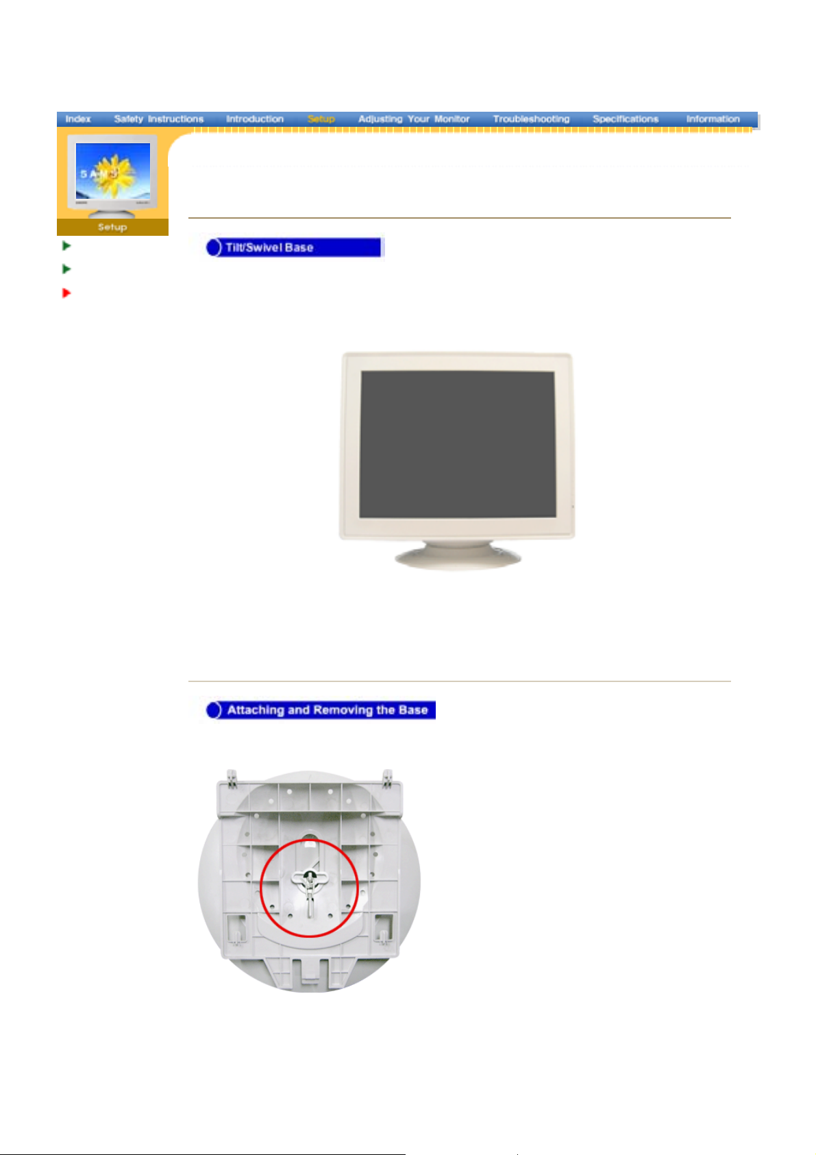
Ti lt/ Swive l Ba se
Attaching and Removing th e Base
|
With the built-in pedestal, you can tilt and/or swivel the monitor for the most comfortable
viewing angle.
Note: The base is detachable.
If y our monitor was supplied with the base detached, attach the base as follows.
Remove the twist-tie before attaching the base to the monitor.
Page 23

Attaching the Base
1. Place the monitor upside-down on a flat work surface.
2. Align the tabs on the base with the corresponding slots on the bottom of the monitor.
3. Press the base onto the monitor until the tabs are fully engaged in the slots.
4. Push the base toward the front of the monitor until the release latch clicks into the locked
position.
* Do not bend the snap.
Removing the Base
5. Squeeze and pull up on the release latch on the base.
6. Push the base toward the back of the monitor and lift up to remove the base.
Note: The base will align with the monitor slots in only one position.
Page 24

|
|
Adjusting Yo ur Monitor
User con trol butt ons
Direct-Access Feature s
OSD Fu nctions
MagicTune™
Highligh t III
User control buttons
SyncMaster 797MB
1. Opens the OSD menu. Al so used t o exit the OSD menu or r eturn to the previous men u.
2. These b uttons all ow you t o highlig ht and a djust item s in t he men u.
3. Used to s elec t the OSD menu.
a. MagicBright2 ™ is a ne w fea ture providing opt imu m viewing env iron ment d epending on the con tents of the im age
you are watching.
b. The Highligh t Zone ensures clea r image s o n TVs , video c onfe rencing systems or photos by em phasizing a
certain area on the screen .
Direct -Acces s Features
Brightness
Page 25

| MagicBright2™ |
MagicBright2™
| Highlight III |
Highlig ht III
Then pus h the MagicBright2™ button agai n to circl e through a vai lable pr econfigured
modes.
The Highlight Zo ne ensur es the clear and s harp di splay o f animate d multi media or photo
images by enhan cing t he brightness of a certain ar ea on th e screen.
OSD Functions
Page 26

osd Descript ion
Adjust t he Bright ness.
Adjust t he Contrast.
A "Moiré" pattern c an app ear on y our screen, looking like a series of concent ric circles or
arcs. To eliminat e this patter n, use the horizontal m oire ad justments.
A "Moirë" pattern c an app ear on y our screen, looking like a series of concent ric circles or
arcs. To eliminat e this patter n, use the vertic al moire a dju stm ents.
The Degau ss fea ture will r emove color im purities c aused by magnetic fields.
Use the recall feature to reset these m onitor setting s to their o riginal le vels: Position, Si ze ,
Pincushion, Trapezoid, Parallelogram, Pinba lan ce, Rotat ion, H- Moire,a nd V-Moire.
Note: If yo u have selected "Yes", all settings listed above w ill be res et. All other setti ngs
will remain the sam e.
osd Descript ion
Color temperature is a meas ure of th e 'w armth' o f the imag e colo rs. The av ailable range
is between 5 000 to 9300K.
Page 27

Used to a djust the mon ito r color sett ing.(R ed)
Used to a djust the mon ito r color sett ing.(Gr een)
Used to a djust the mon ito r color sett ing.(Blue)
When you adju st the Bright ness and C ontrast after sRG B mode is select ed, sRGB mo de
exits.
osd Descript ion
Follow th ese instructions to chang e the ho rizontal pos ition of the monitor's entire disp lay.
Follow th ese instructions to chang e the vetical pos ition of the moni tor's entire display.
Follow th ese instructions to chang e the ho rizontal s ize of the monit or's enti re display .
Follow th ese instructions to chang e the ver tical size of the m onitor's entire displ ay.
Adjust t he pincus hio n setting when the sides of the displa y are b owed in or bowed o ut.
Adjust t he pinbalanc e setting when the sid es of the d is play ar e bow ed toward s th e left or
right.
Adjust t he trapezoid setting when the top or botto m of the display is too lar ge or sm all.
Adjust t he parallelogr am sett ing when the dis play is leaning left or rig ht.
Adjust t he rotation s etting w hen th e entire displ ay is tilted left or right.
Adjust t he side pi n corne r correction w hen the top or bottom of the display is too large or
sma ll .
Page 28

OSD Descript ion
Used to t urn the Highlight Z one f eatures on or off.
Note : When "O FF" is sel ected, th e user cannot c hoose a ny other Highli ght Zone
features .
This function is to move th e Highli ght Zone h orizontally.
This function is to move th e Highli ght Zone v ertically.
This function is to adjust the horizontal size of the Highlight Zon e.
This function is to adjust the vertica l si ze of the Highlig ht Zone.
This function is to execute th e Highl ight Zone.
This function is to use the contrast o f the H ig hlight Zone.
This function is to adjust the sharpn ess of the High light Zone.
You can s ee th e frequenc y (user control mode) us ed by th e user, the polar ity of the operationa l signals, the d efault
frequenc y (defa ult mode) set wh en you buy t he mon itor and the res olu tion le vel.
Note : These scr eens do n ot allo w any changes to the settings, they ar e for informa tio n only.
Page 29

|
|
Adjusting Yo ur
Monitor
User con trol butt ons
Direct-Access Feature s
OSD Fu nctions
MagicTune™
Highligh t III
User control buttons
SyncMaster 997MB
1. Opens the OSD menu. Al so used t o exit the OSD menu or r eturn to the previous men u.
2. These b uttons all ow you t o highlig ht and a djust item s in t he men u.
3. Used to s elec t the OSD menu.
a. MagicBright ™ is a ne w fea ture providing opt imu m viewing env iron ment d epending on the con tents of the im age
you are watching.
b. The Highligh t Zone ensures clea r image s o n TVs , video c onfe rencing systems or photos by em phasizing a
certain area on the screen .
Direct -Acces s Features
Brightness
Page 30

| MagicBright ™ |
MagicBright™
| Highlight III |
Highlig ht III
Then pus h the MagicBright™ button agai n to circl e through a vai lable pr econfigured mod es.
The Highlight Zo ne ensur es the clear and s harp di splay o f animate d multi media or photo
images by enhan cing t he brightness of a certain ar ea on th e screen.
OSD Functions
Page 31

OSD Descript ion
Adjust t he Bright ness.
Adjust t he Contrast.
A "Moiré" pattern c an app ear on y our screen, looking like a series of concent ric circles or
arcs. To eliminat e this patter n, use the horizontal m oire ad justments.
A "Moirë" pattern c an app ear on y our screen, looking like a series of concent ric circles or
arcs. To eliminat e this patter n, use the vertic al moire a dju stm ents.
The Degau ss fea ture will r emove color im purities c aused by magnetic fields.
Use the recall feature to reset these m onitor setting s to their o riginal le vels: Position, Si ze ,
Pincushion, Trapezoid, Parallelogram, Pinba lan ce, Rotat ion, H- Moire,a nd V-Moire.
Note : If yo u have sel ected "Yes", all settings listed above will be r eset. All other settings
will remain the sam e.
(Optio n)
Use this menu to choose between the signal s ource conn ected to t he BNC connector i nput
and the signal sour ce connected to the D -SUB connector input.
Note : W hen you a re finished, wai t for a few secon ds and the screen w il l blank then
display the image from the new si gnal sour ce(oth er comp uter). A cable m ust be connecte d
to both inputs to use this function.
Page 32

OSD Descript ion
Color temperature is a meas ure of th e 'w armth' o f the imag e colo rs. The av ailable range
is between 5 000 to 9300K.
Used to a djust the mon ito r color sett ing.(R ed)
Used to a djust the mon ito r color sett ing.(Gr een)
Used to a djust the mon ito r color sett ing.(Blue)
When you adju st the Bright ness and C ontrast after sRG B mode is selected, sRGB m ode
exits.
OSD Descript ion
Follow th ese instructions to chang e the ho rizontal pos ition of the monitor's entire disp lay.
Follow th ese instructions to chang e the vetical pos ition of the moni tor's entire display.
Follow th ese instructions to chang e the ho rizontal s ize of the monit or's enti re display .
Follow th ese instructions to chang e the ver tical size of the m onitor's entire displ ay.
Adjust t he pincus hio n setting when the sides of the displa y are b owed in or bowed o ut.
Adjust t he pinbalanc e setting when the sid es of the d is play ar e bow ed toward s th e left or
right.
Adjust t he trapezoid setting when the top or botto m of the display is too lar ge or sm all.
Adjust t he parallelogr am sett ing when the dis play is leaning left or rig ht.
Adjust t he rotation s etting w hen th e entire displ ay is tilted left or right.
Adjust t he side pi n corne r correction w hen the top or bottom of the display is too large or
sma ll .
Page 33

OSD Descript ion
Used to t urn the Highlight Z one f eatures on or off.
Note : When "O FF" is sel ected, th e user cannot c hoose a ny other Highli ght Zone
features .
This function is to move th e Highli ght Zone h orizontally.
This function is to move th e Highli ght Zone v ertically.
This function is to adjust the horizontal size of the Highlight Zon e.
This function is to adjust the vertica l si ze of the Highlig ht Zone.
This function is to execute th e Highl ight Zone.
This function is to use the contrast o f the H ig hlight Zone.
This function is to adjust the sharpn ess of the High light Zone.
You can s ee th e frequenc y (user control mode) us ed by th e user, the polar ity of the operationa l signals, the d efault
frequenc y (defa ult mode) set wh en you buy t he mon itor and the res olu tion le vel.
Note : These scr eens do n ot allo w any changes to the settings, they ar e for informa tio n only.
Page 34

Overview | Installation | OSD Mode | Uninstall | Troubleshooting
Overview
What is MagicTune™?
Monitor performance can vary due to the graphics card, host computer lighting conditions
and other environmental factors. In order to get the best image on a monitor requires you
to adjust it for your unique setting. Unfortunately, the manual controls available to tune the
image often prove to be challenging. Proper adjustment (tuning) requires an easy to use
program that goes through a step-by-step process to obtain the best overall picture quality.
In most cases even simple adjustments to Brightness, or Contrast require navigation of the
multi -leve l, o n -scree n di splay (OSD) me nu s t hat a re not e as y to u nd e rst and. Fu rth ermore,
ther e is no f eedback to assist in co rrect ly settin g the co nt rols of the m onitor. MagicTune is
a software utility that guides you through the tuning process with easy to understand
instructions and back ground patterns designed for each monitor control.
Basic Functionality
Magic Tune is a software utility that allows monit or adjustment and color tuning using the
Display Data Channel Command Interface (DDC/CI) protocol. All adjust ments to the
display are controlled via software to eliminate the need to use the monitor on-screen
display (OSD). MagicTune supports Windows 98SE, Me, 2000, NT, XP Home, and XP
Professional.
MagicTune allows for quick accurate tuning of the display with the ability to easily save
and use mo nito r co nf ig u rations that are best suit ed for you.
OSD M ode
The OSD mode allows easy adjustment of monitor settings without taking pre-defined
steps. You can access t he desired menu item to s et wit h ease.
Page 35

Overview | Installation | OSD Mode | Uninstall | Troubleshooting
Installation
1. Ins ert the installation CD into the CD-ROM drive.
2. Click the MagicTune™ installation file.
3. Select installation Language, Click "Next".
4. When the InstallationShield Wizard window appears, click "Next."
5. Select "I a gre e to the term s of the lice nse agreement" to accept the term s of use.
Page 36

6. Choose a folder to install the MagicTune program.
7. Click "Install."
8. The "Installationation Status" window appears.
Page 37

9. Click "Finish."
10. When the installation is complete, the MagicTune 2.5 executable icon appears on your
desktop.
Double -click the ic on to start the progr am.
Magictune execution icon may not appear depending on specification of
comp ut er system or monitor. I f tha t happ ens, pres s F5 Ke y.
11. The following window appears if the installation is successful.
Page 38

12. The followin g error message indicates that the system is using a video ca rd that is not
supported by MagicTune.
Installationation Problems
The installation of MagicTune™ 2.5 can be affected by such factors as the video card,
motherboard and the network environment.
See
"Troubleshooting"
if you have trouble during installation.
System Requirements
OS
z
Windows 98 SE
z
Windows Me
z
Windows NT
z
Windows 2000
z
Windows XP Home Edition
z
Windows XP Professional
Ha rd w ar e
z
32MB Memory above
z
25MB H a rd disk s pace ab o ve
* For more information, visit the MagicTune website.
Page 39

Overview | Installation | OSD Mode | Uninstall | Troubleshooting
MagicTune allows for quick accurate tuning of the display with the
ability to easily save and use monitor configurations that are best
suited for you.
z
OSD mode may appear inconsistent with the
explanati on in gu id ance book depend in g on
specification of each monitor.
OSD Mode
The OSD mode makes ers the adjustment of settings on all monitors easy. When
selected , each tab on top of the control window displays the general descriptions of
the sub-menu items for adjustment. When selected, each tab displays a list of
menus. For quick adjustment of the monitor settings, the OSD mode allows easy and
convenient access to all tabs and sub-menu items.
Button Tab Definition
OK
Reset
Applies any changes made and exits MagicTune.
Restores the monitor values displayed on the active control window
to the manufacturer-recommended values .
Exits MagicTune without applying the changes made. If you have
Page 40

not made any changes in the control window, clicking "Cancel" does
Cancel
not cause any actions.
Picture Tab Definition
Allows the user to adjust the screen settings to the desired values.
Brightness Contrast MagicBright
Makes the entire screen brighter or darker. The detailed data of the
Brightnes s
images in the dark areas can be lost if the brightness is not
adjusted to the proper level. Adjust the brightness for best viewing
conditions.
Contra st
Adjusts the difference in brightness between the bright and dark
areas on screen. Determines the crispness of the images.
MagicBright™ is a new feature providing the optimum viewing
environment depending on the contents of the image you are
watching. Currently four different modes are available. Each mode
has its own pre-configured brightness value. You can easily select
one of four settings by simply pressing the MagicBright™ control
button.
z
19" or above
1. Text: For documentations or works involving heavy text.
2. Internet: For working with a mixture of images such as text
Page 41

and graphics.
3. Game: For watching motion pictures such as a Game.
4. Entertain: For watching motion pictures such as a DVD or
VCD.
z
Mag icBright™
Less than 19"
1. Text: For documentations or works involving heavy text.
2. Internet: For working with a mixture of images such as text
and graphics.
3. Entertain: For watching motion pictures such as a DVD or
VCD.
Color Tab Definition
Adjusts the "warmth" of the monitor background or image color.
Color Tone Color Control
Color Tone
Color Contro l
The tone of the color can be changed.
z
Warm - Normal - Cool
z
Cus tom
Adjusts of the monitor image color.
You can change the monitor color to your desired color.
z
R - G - B
z
sRGB
Page 42

Image Tab Definition
Adjusts the Position, Size and Rotation values.
Geometry 1
Rotation Size Position
Geometry 2
Pincushion Pinbalance Trapezoid Parallelogram
Other
Moire Degauss Sidepin Corner Top
Sidepin Corner Bottom Pinbalance Corner Top
Pinbalance Corner Bottom
Adjusts the Position, Size and Rotation values.
Geometry 1
z
Position
z
Size
z
Rotation
Adjusts the Pincushion, Pinbalance, Trapezoid and Parallelogram
values.
Geometry 2
z
Pincushion
z
Pinbalance
z
Trapezoid
z
Parallelogram
Other
Adjusts the Moire, Degauss, Sidepin Corner, and Pinbalance
Corner values.
z
Moire
z
Degauss
z
Sidepin Corner Top
z
Sidepin Corner Bottom
Page 43

z
Pinbalance Corner Top
z
Pinbalance Corner Bottom
Option Tab Definition
You can configure MagicTune using the following options.
Loads the Preferences Dialog Box. Preferences in use will have an
"V" in the check box. To turn on or off any Preference, position the
cursor over the box and click.
z
Preferences
Enable task tray menu .
- To access the MagicTune menus, click the icon on the [task
tray menu].
The menus are not displayed if the [Enable System Tray] is
deselected in [Options] ' [Preferences].
z
Select Language - The language chosen affects only the
language of the OSD.
Sup port Tab Definition
Shows the Asset ID and the version number of the program, and allows you to use
the Help feature.
Page 44

Hel p
Visit the MagicTune website or click to open the Help files (User
Manual) if you need any help installing or running MagicTune.
The User Manual opens within a basic browser window.
Asset ID
Version
Opens a monitor info window showing the manufacturing date of
the monitor.
Displays the version number of MagicTune.
Page 45

Overview | Installation | OSD Mode | Un i ns ta l l | Troubleshooting
Uninstall
The MagicTune program can be removed only by using the "Add or Remove Programs"
option of the Windows Control Panel.
Perform the following steps remove MagicTune.
1. Go to [Ta sk Tra y] ' [ Start] ' [Settings] and se lect [C ontr ol P anel] in the menu. If the
program ru ns on W in do ws X P, go to [ Control P ane l] i n th e [Start] menu.
2. Click the "Add or Remove Programs" icon in Control Panel.
3. In the "Add o r Remove Programs" screen , sc roll down to find "Ma gic Tune. " Clic k
on it to highlight it.
4. Cli ck th e "Change/Rem ove" b utton to remo ve th e p rogram.
5. Click "Yes" to begin the uninstall process.
6. Wait until the "Uninstall Complete" dialog box appears.
Visit the MagicTune
answers) and software upgrades.
website
for technical support for MagicTune, FAQs (questions and
Page 46

Overview
|
Installation
|
OSD Mode
|
Uninstall
|
Troubleshooting
Troubleshooting
MagicTune may not work in case monitor is replaced or driver of graphic card is updated
while MagicTune is operating. If so, please restart the system.
Check when MagicTune does not function properly.
* MagicTune feature is found only on PC (VGA) with Window OS that supports Plug and
Play.
* To check whether your PC is available for MagicTune feature, follow the
steps below (When Windows is XP);
Control Panel -> Performance and Maintenance -> System -> Hardware -> Device
Manager -> Monitors -> After deleting Plug and Play monitor, find 'Plug and Play
monitor' by searching new Hardware.
* MagicTune function is not available when BNC is used for a signal input.
Use D-sub to activate MagicTune function. (BNC is optional - 19" Model Only)
Visit the MagicTune
answers) and software upgrades.
website
for technical support for MagicTune, FAQs (questions and
Page 47

The Highlight Zone ensu res the clear and sharp d isplay
of animated m ultimedia or pho to images by enha ncing
the brightness o f a certain area o n the screen .
Hig hlight Zone III fea tures a c o mbinatio n of the circ uitry
an d the pr og ram bu ilt on the pr oprietary techn ology of
SE C.
This offers an easy-to-use interface that highlig hts the
vid eo -playin g portion of your mult ime dia progr am by
au tomatically detecting an d highlig ht the desired area
by drag ging.
The Highligh t Zon e p rov id es op tima l display of mo vin g
pictures. S o, text m ay app ear blurry in the Highlight
Zone.
Automatic detect
Manual detect
Exit Program
Auto Dete ct
Pictu re Se tt ing
F ull S creen
High li ght O ff
Other Features
SyncMaster 797MB
Page 48

The Highlight Zone ensures the clear and sharp display
g
)
of animated multimedia or photo images by enhancing
the brightness of a certain area on the screen.
Highlight Zone III features a combination of the circuitry
and the program built on the proprietary technology of
SEC.
This offers an easy-to-use interface that highlights the
video-playing portion of your multimedia program by
automatically detecting and highlight the desired area
by dragging.
The Highlight Zone provides optimal display of moving
pictures. So, text may appear blurry in the Highlight
Zone.
When BNC is used for signal input, Highlight Zone can
be adjusted by OSD, not by software system.
To adjust Highlight Zone using software system,
use D-sub for si
nal input. (BNC is optional
Automatic detect
Manual detect
Exit Program
Auto Detect
Picture Setting
Full Screen
Highlight Off
Other Features
SyncMaster 997MB
Page 49

Automatic detect
Manual detect
Exit Program
Auto Dete ct
Pictu re Se tt ing
F ull Screen
High li ght O ff
Other Features
Automatic d etect
1. When the Highlight program is running, the monitor automatically detects the video-playing portion of your multimedia progr am and activates the
Highlight Z one feature. No selection is necessary.
Major multimedia progr ams: Windows Media P layer, RealPlayer 8.0, video players on the broadcasters¡¯ webs ites, etc.
However, Automatic Detect may not work with a DVD player. (In this case, change the setting to Manual Detect mode to create a Highlight Zone.)
Select 'Off' in Auto Detect menu when you wish to deac tivate the Automatic Detect feature.
Since this disables the Auto Detect capability of the monitor, the monitor does not automatically create a Highlight Zone.
(When you first install the program, Automatic Detect is set to 'O n'.)
Note 1 : When OSD is selected while the Auto Detect is running, Highlight Zone turns off temporarily not to disturb adjustment of display c onditions
such as brightnes s and color.
Page 50

Automatic detect
Manual detect
Exit Program
Auto Dete ct
Pictu re Se tt ing
F ull S creen
High li ght O ff
Other Features
Manu al d et ect
In M anual Detect mode, you can either select a window or use the Drag function to c reate a Highlight Zone.
1. Selecting a window: Click the Highlight icon( )on the Windows taskbar once to activate( )the c ursor.
Move the cursor onto the window of your choice and c lick once to Highlight the window.
2. Drag: Click the Highlight ic on( )on the W indows task bar once to activate( )the c ursor.
Click and hold the left mous e button, then drag the cursor to create a rectangle that covers the desir ed ar ea. This rectangle bec om es th e H i g h li g ht Z on e .
Note 1 :
Note 2 :
Note 3 : When OSD is selec ted while the Manual Detect is running, Highlight Zone turns off temporarily, as it does when A uto detect is running.
When the mouse cursor is activated( )and it is necessary to de-activate it to us e it for other task s, right click your mouse,
or put the activated cursor ( )on the taskbar and c lick. When de-activ ated, the icon on the screen changes bac k to the one shown before activation.
You can determ ine whether the Highlight feature is on/off by the appearance of the icon on the taskbar. On( ), Off( )
Page 51

Exit Progr am
1. Exits the Highlight program.
Automatic detect
Manual detect
Exit Program
Auto Dete ct
Pictu re Se tt ing
F ull Screen
High li ght O ff
Other Features
Page 52

Automatic detect
Manual detect
Exit Program
Auto Dete ct
Pictu re Se tt ing
F ull Screen
High li ght O ff
Other Features
Auto Detect
1. Allows user to disable Auto Detect when nec essary.
Once selected, this function saves the selection and keeps it in the memor y regardless of exiting or res tarting the program.
When selected, a check mark (V) appears.
Page 53

Automatic detect
Manual detect
Exit Program
Auto Dete ct
Pictu re Se tt ing
F ull Screen
High li ght O ff
Other Features
Picture Setting
1. Can be selected only when the Highlight Z one function is on. When selected, a menu window appears whic h can be used to adjust Contrast
and Sharpness within the Highlight Zone.
After changing the setting, select OK to save the changes, or Cancel to return to the previous setting.
Page 54

Automatic detect
Manual detect
Exit Program
Auto Dete ct
Pictu re Se tt ing
F ull Screen
High li ght O ff
Other Features
Full Scree n
1. Full Screen: Place the c ursor on the Highlight icon( )on the Windows taskbar and right click your mouse once. T hen select Full Screen from the menu.
Page 55

Hig hlight Off
1. Cancels the selection of a Highlight Zone and reverts to the original screen.
Automatic detect
Manual detect
Exit Program
Auto Dete ct
Pictu re Se tt ing
F ull Screen
High li ght O ff
Other Features
Page 56

Automatic detect
Manual detect
Exit Program
Auto Dete ct
Pictu re Se tt ing
F ull S creen
High li ght O ff
Other Features
Other Fea tures
The Highlight Z one function remembers the variables of the selected areas in Automatic and Manual Detect modes, res pectively.
1. If the window selected as a Highlight Zone is moved or its s iz e changed, the Highlight Zone c hanges ac cordingly.
2. If an un-selected window overlaps the window s elected as a Highlight Zone, the Highlight Zone of the s elected window tur ns off.
However, it does not turn off the Zone com pletely and only m akes the window shift to standby mode while the s ettings are s aved. When the window is re-
activated, the Highlight Zone turns on again with the s ettings unchanged.
3. If another un-ov erlapped window beside one with a Highlight Zone is selec ted as a Highlight Z one, Highlight Zone function is activated for the two
separate windows sim ultaneously. (Up to two windows can be selected as a Highlight Zone and if another window is selected as a Highlight Zone, the
Highlight Z one of the previous windows turns off.)
When the Highlight Zone is created using the Drag function, the Zone functions independently of the above since it uses a random portion of the screen
instead of a particular window.
Note 1 : How to cancel the saved var iables of a selected window.
Note 2 : The changes saved under Picture Setting of the Highlight Zone menu remain effective even after the program is clos ed using Ex it Program.
1) When a window selected in Automatic Detect mode is replac ed with another window also selected in Automatic Detect mode,
only the last selection is saved, and the Highlight Zone function is de-activated for the previous windows .
2) In Manual Detect mode, only the window (or the frame window) created last is saved, and the Highlight Zone function is de-activ ated for the
previous windows.
The Highlight Z one is de-selected when the pr ogr am used to create the selected window is closed. The v ariables of the Highlight Z one created us ing
the Drag function are not saved.
(The next tim e you start the Highlight Zone program, the settings are shown as prev iously saved.)
Page 57

Check List
r
Q & A
Self-Test Featur e
Check
Before calling for service, check the information in this section to see if you can remedy any
problems yourself. If you do need assistance, please call, the phone number on the
Information section or contact y our deale
Symptom Check List Solutions
No images on the
screen. I cannot turn
on the monitor.
.
Is the power cord connected
properly?
Can you see " " on the
screen?
Check the power cord connection
and supply.
Check the signal cable connection.
If the power is on, reboot the
computer to see the initial
screen(the login screen), which
can be seen.
Can you see " " on the
screen?
There is no image on the
screen. Is the power indicator
on the monitor blinking at 1
second intervals?
If the initial screen (the login screen)
appears, boot the computer in the
applicable mode (the safe mode for
Windows ME/XP/2000) and then
change the frequency of the video
card.
(Ref er to t he Preset Timing Modes)
Note: If the initial screen (the login
screen) does not appear, contact a
service center or your dealer.
You can see this message when the
signal from the video card exceeds
the maximum resolution and
frequency that the monitor can
properly handle.
Adjust the maximum resolution and
frequency that the monitor can
properly handle.
The monitor is in PowerSaver mode.
Press a key on the keyboard or move
the mouse to activate the monitor
and restore the image on the screen.
The image on the
screen is shaking.
The screen shows
strange colors or
jus t black and white.
Check the monitor configuration
to see if it is in Interlace M ode.
(Int erlace Mode: Vertical
The signal from the video card
exceeds the maximum resolution and
frequency of the monitor.
frequency 43Hz, 87Hz(i), etc)
Are there any magnetic
products such as a power
adapter, speaker or a high
Move the monitor away from
anything that can create a strong
magnetic field.
voltage wire near by?
Is the voltage stable? The screen image can appear to
shake or vibrate at a particular t ime
of day due to low supply voltage.
The screen image can also app ear to shake or vibrate if there is a
problem with the video car d or th e computer's main board.
Is the screen displaying only
one color as if looking at the
screen through a cellophane
paper?
Check the signal cable connection.
Make sure the video card is fully
inserted in it's slot .
Page 58

Have the screen colors become
p
y
stra nge after running a program
or due to a crash between
applications?
Reboot the computer.
The screen
suddenly has
become
unbal anced.
The screen is out of
fo cus o r OSD
cannot be adjusted.
The screen is
par tial ly distorted.
LED is blinking but
no images on the
screen.
Has the video card been set
properly?
Have you changed the video
card or the driver?
Have you adjusted the
re solution or frequency to the
monitor?
The screen can be unbalanced due to the cycle of the video card
signals. Readjust Position by referring to the OSD.
Have you adjusted the
re solution or frequency on the
monitor?
Are there any magnetic
products such as an adapter,
speaker or a high voltage wire
near the monitor?
Is the frequency properly
adjusted when checking the
Display Timing on the menu?
Set the video card by referring to the
video card manual.
Adjust screen image position and
size using the OSD.
Adjust the resolution and frequency
at the video card.
(Ref er to t he Preset Timing Modes).
Adjust the resolution and frequency
of the video card.
(Ref er to t he Preset Timing Modes).
Enter the OSD and perform a
"Degauss".
Keep the monitor away from any
magnetic products.
Adjust the frequency properly by
re ferring to the video card manual
and the Preset Timing Modes.
(The maximum f requency per
re solution may differ from product to
product.)
The re are only 16
colors shown on the
screen. The screen
colors have
changed after
changing the video
card.
The re is a message
that r eads
"Unrecognized
moni tor, Pl ug & Play
(VESA DDC) monitor
foun d".
Che ck the fo llowing items i f there is trouble with the mo nitor.
1. Check if the power cord and the video cables are properly connected to the computer.
2. Check if the computer beeps more than 3 times when booting.
(If it does, request an after-service for the main board of the computer.)
3. If you installed a new video card or if you assembled the PC, check if the installed the adapter
(video) driver and the monitor driver.
4. Check if the scanning ratio of the video screen is set at 75Hz or 85Hz.
(Do not exceed 60Hz when using the maximum res olution.)
5. If you have problems in installing the adapter (video) driver, boot the computer in Safe Mode,
re move the D isplay Adapter at the "Control Panel, System, Device A dministrator" and then
re boot the com
Tips for Highlight Zone
Have the Windows colors been
set properly?
Has the video card been set
properly?
Have you installed the monitor
driver?
See the video card manual to
see if the Plug & Play (VESA
DDC) function can be
supported.
uter to reinstall the adapter (video) driver.
For Windows ME/XP/2000:
Set the colors properly at the
Control Panel, Di splay, Settings .
Set the video card by referring to the
video card manual.
Install the monitor driver according to
the Driver Installation Instructions.
Install the monitor driver according to
the Driver Installation Instructions.
1. To protect CDT against the screen brightness, the H ighlight Zone function persists for three
hours and then automaticall
stops. So please reset it to continue.
Page 59

2. Once the Highlight Zone has been switched off, you can't select any of the other menus within
the Hightlight Zone.
3. When the Highlight Zone function is operated, the surrounding brightness of screen may
become dark.
4. Depending on the video card you use, a color saturation phenomenon may occur in the
Highlight Zone. In this case, slightly lower the contrast of the Highlight Z one and the color
saturation will be reduced.
Note: If problems repeatedly occur, contact an authorized service center.
Page 60

Check List
Q & A
Self-Test Feature
Check
General Q & A
Highlight Zone III Q & A
|
1. General Q & A
Question Answer
How can I change the frequency? Frequency can be changed by reconfiguring the video
card.
Note that video card support can vary, depending on the
version of the driver used.
(Refer to the computer or the video card manual for
details.)
How can I adjust the resolution? Windows ME/XP/2000: Set the resolution at the
Panel, Display, Settings
.
* Contact the video card manufacturer for details.
How can I set the Power Saving
function?
Windows ME/XP/2000: Set the function at BIOS-SETUP
of the computer or the screen saver. (Refer to
Windows/Computer Manual).
The monitor makes a sound when it
is turned on.
This is normal as some sound may be generated when
the metal case and the electromagnet, which are installed
to block any electromagnetic waves, interact with each
other.
How can I clean the outer
case/Picture tube?
Disconnect the power cord and then clean the monitor
with a soft cloth, using either a cleaning solution or plain
water.
Do not leave any remains of the detergent nor scratch the
case. Do not allow any water to go inside the monitor.
2. Highlight Zone III Q & A
Control
Question Answer
The program does not function
properly.
Started a multimedia program but the
Highlight Zone function does not
Highlight Zone III features a combination of circuitry and
software built on proprietary technology of SEC.
Therefore, the Highlight Zone III fea ture is found only on
SEC monitors that support the feature.
Check if your monitor supports the Highlight Zone III
feature.
If not, the Highlight Zone III icon will show a message
saying, "No Connection" ( )Connect the monitor
properly before using it. Neither Automatic Detect or nor
Manual Detect function while the icon shows the
message, "No Connection". You can only exit the
program.
Check the Highlight Zone III menu and see if Disable
Auto Detect is selected.
Page 61

automatically activate. When selected, the Highlight Zone function is not
automatically activated.
The function may not be activated automatically for some
multimedia programs.
In this case, use Manual Detect instead.
See Manual Detect under (
Highlight Zone III)
Check the color settings and see if sRGB is selected.
When sRGB is selected, the Highlight Zone III function
remains de-activated in order to maintain the sRGB color
attributes.
Changed the setting to Highlight
Zone in Manual Detect mode but the
Highlight Zone feature has not been
activated
Check the color setting of the monitor and see if sRGB is
selected.
When sRGB is selected, the Highlight Zone function
remains de-activated in order to maintain the sRGB color
attributes.
Some of the windows may not be selected when Highlight
Zone function is on.
Want to turn the Auto Detect function
off.
Don¡¯t know whether the Highlight
program is running.
Set Disable Auto Detect to off from the Highlight Zone III
menu.
Highlight Zone III
See (
functions)
Check the icon on the taskbar.
( ) indicates the function is activated and ( )shows it
has been deactivated.
When a Highlight Zone is on, the rest
of the screen dims.
Monitors with the Highlight Zone feature are equipped
with an Automatic Beam Control function. When
activated, this may cause slight dimming of the
surrounding screen. However, this does not indicate a
malfunction of any kind, and it is safe to continue to use
the product.
The Highlight Zone appears too dark. Check the Contrast value in Picture Setting and adjust it
for your ideal viewing.
Want to adjust the position and size
of the Highlight Zone.
You can change the position and/or the size of the
Highlight Zone easily using the Manual Detect function.
Highlight Zone III
See (
functions)
Cannot select Picture Setting. The Picture Setting feature can be selected only when
the Highlight Zone function is on.
Turn the Highlight Zone function on before selecting
Picture Setting.
Page 62

Self- Test Featur e C heck
Warning Messa ges
|
Environment
|
Useful Tips
|
Check Li st
Q & A
Self-Test
Feature Check
Your monitor provides a self test feature that allows you to check whether your monitor is
functi on in g pr op erly.
1. Turn off both your computer and the monitor.
2. Unplug the video cable from the back of the computer.
3. Turn on the monitor.
If your monitor works normally, the following screen appears.
SyncMaster 797MB SyncMaster 997MB
Failure of any of the boxes to appear indicates a problem with your monitor. This box
also appears during normal operation if the video cable becomes disconnected or
damaged.
4. Turn off your monitor and reconnect the video cable; then turn on both your computer and the
monitor.
If your monitor screen remains blank after using the previous procedure, check your
video controller and computer system; your monitor is functioning properly.
If there is something wrong with the input signal, a message appears on the screen or
the screen goes blank although the power indicator LED is still on. The message may
indicate that the monitor is out of scan range or that you need to check the signal cable.
SyncMaster 797MB SyncMaster 997MB
The location and the position of the monitor may influence the quality and other
features of the monitor.
1. If there are any sub woofer speakers near the monitor, unplug and relocate the woofer to
another room.
2. Remove all electronic devices such as radios, fans, clocks and telephones that are within 3
feet (one meter) of the monitor.
3. Degauss the monitor if any devices were removed from the area.
Page 63

z
A monitor recreates visual signals received from the computer. Therefore, if there is trouble
with the computer or the video card, this can cause the monitor to become blank, have poor
coloring, noise, Sync. Out of Range, etc. In this case, first check the source of the problem,
and then contact a service center or your dealer.
z
Judging the monitor's working condition
If there is no image on the screen or a "Sync. Out of Range" message comes up, disconnect
the cable from the computer while the monitor is still powered on.
{
If there is a message coming up on the screen or if the screen goes white, this means
the monitor is in working condition.
{
In this case, check the computer for trouble.
Page 64

General
PowerSaver
Preset Timing
Modes
General
Model Name SyncMaster 797MB
Picture Tube
Typ e 17"(43cm) DynaFlat (40.6cm viewable)
Deflection angle 90 °
Dot Pitch 0.20mm (Horizontal)
Screen type Aluminized tri-color phosphor dot trio with black matrix.
Anti-doming invar shadow mask.
Multi-layer coated with anti-static.
Maximum Resolution
1600 x 1200@76Hz
Active Display
Horizontal 312 ± 4 mm
Vertical 234 ± 4 mm
Synchronization
Horizontal 30 ~ 96 kHz
Vertical 50 ~ 160 Hz
Input Signa l Defi ni tion
Video Signal RGB, Analog 0.7 Vpp positive at 75 ohms
Sync Signal Separate H/V sync, TTL level, positive or negative
Display Color
Unlimited
Maximum Pixel Clock
250 MHz
Power Supply
AC 90 ~ 264 VAC rms, 60/50 Hz ± 3Hz
Power Consumption
Less than 90W
Dimensions (WxDxH)
401 x 410 x 378mm (After installation of Stand)
Wei ght
14.3kg
Environmental considerations
Operating Temperature 32°F ~ 104 °F(0°C ~ 40°C)
Humidity 10% ~ 80%, non-condensing
Storage Temperature -4°F ~113°F ( -20°C ~ 45 °C)
Humidity 5% ~ 95%, non-condensing
Plug and Play Capability
This monitor can be installed on any Plug & Play compatible system. Interaction of the monitor and
computer systems will provide the best operating conditions and monitor settings. In most cases,
monitor installation will proceed automatically, unless the user wishes to select alternate settings.
Note: Design and specifications are subject to change without prior notice.
Page 65

General
PowerSaver
Preset Timing
Modes
General
Model Name SyncMaster 997MB
Picture Tube
Typ e 19"(48cm) DynaFlat (45.8cm viewable)
Deflection angle 90 °
Dot Pitch 0.20mm (Horizontal)
Screen type Aluminized tri-color phosphor dot trio with black matrix.
Anti-doming invar shadow mask.
Multi-layer coated with anti-static.
Maximum Resolution
1600 X 1200@ 76Hz
Active Display
Horizontal 352 ± 3 mm
Vertical 264 ± 3 mm
Synchronization
Horizontal 30 ~ 96 kHz
Vertical 50 ~ 160 Hz
Input Signa l Defi ni tion
Video Signal RGB, Analog 0.7 Vpp positive at 75 ohms
Sync Signal Separate H/V sync, TTL level, positive or negative
Display Color
Unlimited
Maximum Pixel Clock
250 MHz
Power Supply
AC 90 ~ 264 VAC rms, 60/50 Hz ± 3Hz
Power Consumption
Less than 110W
Dimensions (WxDxH)
445 x 457.5 x 416mm (After installation of Stand)
Wei ght
18.2 kg
Environmental considerations
Operating Temperature 32°F ~ 104 °F(0°C ~ 40°C)
Humidity 10% ~ 80%, non-condensing
Storage Temperature -4°F ~113°F ( -20°C ~ 45 °C)
Humidity 5% ~ 95%, non-condensing
Plug and Play Capability
This monitor can be installed on any Plug & Play compatible system. Interaction of the monitor and
computer systems will provide the best operating conditions and monitor settings. In most cases,
monitor installation will proceed automatically, unless the user wishes to select alternate settings.
Note: Design and specifications are subject to change without prior notice.
Page 66

Genera l
r
PowerSave
Preset Timing
Modes
SyncMaster 797MB
This monitor has a built-in power management system called PowerSaver. This system saves
energy by switching your monitor into a low-power mode when it has not been used for a certain
amount of time. The monitor automatically returns to normal operation when you press a key on the
keyboard. For energy conservation, turn your monitor OFF when it is not needed, or when leaving it
unattended for long periods. The PowerSaver system operates with a VESA DPMS compliant video
card installed in your computer. Use a software utility installed on your computer to set up this
feature.
State Normal Operation
Power Indicator Green Green, Blinking
Power Consumption Less than 90W Less than 2W
Power-off Mode EPA/ENERGY
2000
This monitor is EPA E
used with a computer equipped with VESA DPMS functionality.
As an E
the E
NE R GY STAR
NE R GY STAR
NE R GY STAR
®
Partner, SAMSUNG has determined that this product meets
®
guidelines for energy efficiency.
®
compliant and ENERGY2000 compliant when
Page 67

Genera l
r
PowerSave
Preset Timing
Modes
SyncMaster 997MB
This monitor has a built-in power management system called PowerSaver. This system saves
energy by switching your monitor into a low-power mode when it has not been used for a certain
amount of time. The monitor automatically returns to normal operation when you press a key on the
keyboard. For energy conservation, turn your monitor OFF when it is not needed, or when leaving it
unattended for long periods. The PowerSaver system operates with a VESA DPMS compliant video
card installed in your computer. Use a software utility installed on your computer to set up this
feature.
State Normal Operation
Power Indicator Green Green, Blinking
Power Consumption Less than 110W Less than 2W
Power-off Mode EPA/ENERGY
2000
This monitor is EPA E
used with a computer equipped with VESA DPMS functionality.
As an E
the E
NE R GY STAR
NE R GY STAR
NE R GY STAR
®
Partner, SAMSUNG has determined that this product meets
®
guidelines for energy efficiency.
®
compliant and ENERGY2000 compliant when
Page 68

If the signal transferred from the computer is the same as the following Preset Timing Modes, the
y
screen will be adjusted automatically. However, if the signal differs, the screen may go blank while
the power LED is on. Refer to the video card manual and adjust the screen as follows.
Genera l
PowerSaver
Preset Timing Modes
Table 1. Preset Timing Modes
Display Mode
Horizontal
Frequency
(k H z )
Vertical
Frequ ency
(H z)
Pixel Clock
(M Hz )
Sync Polarity
(H /V )
VESA, 640 x 480 37.500 75.000 31.500 -/-
VESA, 1024 x 768 68.677 84.997 94.500 +/+
VESA, 1280 x 1024 91.146 85.024 157.50 +/+
Horizontal Frequen c
The time to scan one line connecting the right edge to the left edge of the
screen horizontally is called Horizontal Cycle and the inverse number of
the Horizontal Cycle is called Horizontal Frequency. Unit: kHz
Verti cal Fr equency
Like a fluorescent lamp, the screen has to repeat the same image many
times per second to display an image to the user. The frequency of this
repetition is called Vertical Frequency or Refresh Rate. Unit: Hz
Page 69

Service
-
Ter ms
Regulato ry
Natur al Color
Authority
AUS TR ALI A :
Samsung Electronics Australia Pty Ltd.
Customer Response Centre
7 Parkview Drive, Homebush Bay NSW 2127
Tel : 1300 362 603
http://www.samsung.com.au/
BRAZIL :
Samsung Eletronica da Amazonia Ltda.
R. Prof. Manoelito de Ornellas, 303, Terro B
Chacara Sto. Antonio, CEP : 04719-040
Sao Paulo, SP
SAC : 0800 124 421
http://www.samsung.com.br/
CANADA :
Samsung Electronics Canada Inc.
Samsung Customer Care
7037 Financial Drive
Mississauga, Ontario
L5N 6R3
1-800-SAMSUNG (1-800-726-7864)
http://www.samsung.ca/
CHILE :
SONDA S.A.
Teatinos 550, Santiago Centro, Santiago, Chile
Fono: 56-2-5605000 Fax: 56 -2-5605353
56-2-800200211
http://www.sonda.com/
http://www.samsung.cl/
COLOMBIA :
Samsung Electronics Colombia
Cra 9 No 99A-02 Of. 106
Bogota, Colombia
Tel.: 9-800-112-112
Fax: (571) 618 - 2068
http://www.samsung-latin.com/
e
mail : soporte@samsung-latin.com
ESPAÑA :
Samsung Electronics Comercial Iberica, S.A.
Ciencies, 55-65 (Poligono Pedrosa) 08908
Hospitalet de Llobregat (Barcelona)
Tel. : (93) 261 67 00
Fax. : (93) 261 67 50
http://samsung.es/
FRANCE :
SAMSUNG ELECTRONICS FRANCE Service
Paris Nord 2
66 rue des Vanesses
BP 50116 Villepinte
95950 Roissy CDG Cedex
Tel : 08 25 08 65 65
Fax : 01 48 63 06 38
http://www.samsungservices.com/
GERMANY :
TELEPLAN Rhein-Main GmbH
Feldstr. 16
64331 Weiterstadt
T. 06151/957-1306
F. 06151/957-1732
* EURO 0.12/Min
http://www.samsung.de/
HUNGAR Y :
Samsung Electronics Magyar Rt.
Page 70

1039, Budapest, Lehel u. 15-17.
-
-55-
y, Ky
-
-
Tel: 36 1 453 1100
Fax: 36 1 453 1101
http://www.samsung.hu/
ITALY :
Samsung Electronics Italia S.p.a.
Via C. Donat Cattin, 5
20063 Cernusco s/Naviglio (MI)
Servizio Clienti: 199.153.153
http://www.samsung
italia.com/
MEXICO :
SAMSUNG ELECTRONICS MEXICO. S.A. DE C.V.
Saturno NO.44, Col. Nueva Industrial Vallejo
Gustavo A.Madero C.P.07700, Mexico D.F. Mexico
TEL. 52-55-5747-5100
Fax. 52-55-47 52 02
RFC: SEM950215S98
http://www.samsung.com.mx/
IMPORTADO POR: SAMSUNG ELECTRONICS MEXICO. S.A. DE C.V.
Saturno NO.44, Col. Nueva Industrial Vallejo
Gustavo A.Madero C.P.07700, Mexico D.F. Mexico
TEL. 52
5747-5100
EXPORTADO POR: Samsung Electronics CO.,LTD.
416, Mae tan-3dong, Yeongtong-gu,
Suwon Cit
oungki-Do Korea
NETHERLANDS/BELGIUM/LUXEMBOURG :
Samsung Electronics Benelux B. V.
Fleminglaan 12 2289 CP Rijiswijk, NEDERLANDS
Service and informatielijn ;
Belgium :0800-95214, http://www.samsung.be/
Netherlands : 0800
2295214, http://www.samsung.nl/
PANAMA :
Samsung Electronics Latinoamerica( Z.L.) S.A.
Calle 50 Edificio Plaza Credicorp, Planta Baja
Panama
Tel. : (507) 210-1122, 210-1133
Tel : 800-3278(FAST)
http://www.samsung
latin.com/
PERU
Servicio Integral Samsung
Av.Argentina 1790 Lima1. Peru
Tel: 51-1-336-8686
Fax: 51-1-336-8551
http://www.samsungperu.com/
PORTUGA L :
SAMSUNG ELECTRONICA PORTUGUESA S.A.
Rua Mário Dioniso, N
o
2 - 1º Drt. 2795-140 LINDA-A-VELHA
Tel. 214 148 114/100 Fax. 214 148 133/128
Free Line 800 220 120
http://www.samsung.pt/
SOUTH AFRICA :
Samsung Electronics,5 Libertas Road, Somerset Office Park,
Bryanston Ext 16. Po Box 70006, Bryanston,2021, South Africa
Tel : 0027-11-549-1621
Fax : 0027-11-549-1629
http://www.samsung.co.za/
SWEDEN/DENMARK/NORWAY/FINLAND :
Samsung Electronics AB
Box 713
S-194 27 UPPLANDS VÄSBY
SVERIGE
Besöksadress : Johanneslundsvägen 4
Samsung support Sverige: 020-46 46 46
Samsung support Danmark : 8088-4646
Samsung support Norge: 8001-1800
Samsung support Finland: 0800-118001
Tel +46 8 590 966 00
Fax +46 8 590 966 50
http://www.samsung.se/
Page 71

THAILAND :
-
HAI SAMSUNG SERVICE CENTER
MPA COMPLEX BUILDING,1st-2nd Floor
175 SOI SUEKSA VIDHAYA SATHON SOI 12
SILOM ROAD ,SILOM,BANGRAK
BANGKOK 10500
TEL : 0-2635-2567
FAX : 0
UKRAINE :
SAMSUNG ELECTRONICS REPRESENTATIVE OFFICE IN UKRAINE
4 Glybochitska str.
Kiev, Ukraine
Tel. 8-044-4906878
Fax 8-044-4906887
Toll-free 8-800-502-0000
http://www.samsung.com.ua/
United Kingdom :
Samsung Electronics (UK) Ltd.
Samsung House, 225 Hook Rise South
Surbiton, Surrey KT6 7LD
Tel. : (0208) 391 0168
Fax. : (0208) 397 9949
< European Service Center & National Service >
Stafford Park 12 Telford, Shropshire, TF3 3BJ
Tel. : (0870) 242 0303
Fax. : (01952) 292 033
http://samsungservice.co.uk/
U.S.A . :
Samsung Electronics America
Service Division
400 Valley Road, Suite 201
Mount Arlington, NJ 07856
1-800-SAMSUNG (1-800-726-7864)
http://samsungusa.com
2635-2556
Page 72

Service
Terms
Regulato ry
Natur al Color
Authority
Dot Pitch
The image on a monitor is composed of red, green and blue dots. The closer the dots, the
higher the resolution. The distance between two dots of the same color is called the 'Dot Pitch'.
Unit: mm
Vertical Frequency
The screen must be redrawn several times per second in order to create and display an image
for the user. The frequency of this repetition per second is called Vertical Frequency or Refresh
Rat e. Unit: Hz
Example: If the same light repeats itself 60 times per second, this is regarded as 60 Hz.
Horizontal Freq uency
The time to scan one line connecting the right edge to the left edge of the screen horizontally is
called Horizontal Cycle. The inverse number of the Horizontal Cycle is called Horizontal
Frequency. Unit: kHz
Interlace and Non-Interlace Methods
Showing the horizontal lines of the screen from the top to the bottom in order is called the NonInterlace method while showing odd lines and then even lines in turn is called the Interlace
method. The Non-Interlace method is used for the majority of monitors to ensure a clear image.
The Interlace method is the same as that used in TVs.
Plug & Play
This is a function that provides the best quality screen for the user by allowing the computer and
the monitor to exchange information automatically. This monitor follows the international
standard VESA DDC for the Plug & Play function.
Resolution
The number of horizontal and vertical dots used to compose the screen image is called
'resolution'. This number shows the accuracy of the display. High resolution is good for
performing multiple tasks as more image information can be shown on the screen.
Example: If the resolution is 1024 X 768, this means the screen is composed of 1024 horizontal
dots (horizontal resolution) and 768 vertical lines (vertical resolution).
Highlight Zo ne III
The Highlight Zone ensures the clear and sharp display of animated multimedia or photo images
by enhancing the brightness of a certain area on the screen.
Highlight Zone III features a combination of the circuitry and the program built on the propriet ary
technology of SEC.
This offers an easy-to-use interface that highlights the video-playing portion of your multimedia
program by automatically detecting and highlight the desired area by dragging.
Mag icBright™
MagicBright™ is a new feature providing the optimum viewing environment depending on the
contents of the image you are watching. Currently four different modes are available. Each
mode has its own pre-configured brightness value. You can easily select one of four settings by
simply pressing the MagicBright™ control button.
Page 73

Regulatory
Service
Ter ms
Regulatory
Natur al Color
Authority
FCC Info rmat ion
European Notice (Europe on ly)
TCO'95-Ecological requirements for personal computers (TCO'95 applied model only)
TCO'99-Ecological requirements for personal computers (TCO'99 applied model only)
TCO'03-Ecological requirements for personal computers (TCO'03 applied model only)
TCO'03 R ecyclin g Information (TC O'03 applied model o nly)
IC Compliance Notic e
|
PCT Notice
|
MPR II Comp li anc e
|
VCCI
|
CCC Not ice
|
|
You must right-click the link for a portable document format (PDF) file and save the file to your hard-disk drive.
Attempting to lin k directly to large PDF files causes your system to freeze.
Regula tory (PD F D oc ume n t)
- To s ave P DF files (files with an extension of .pdf ) to your hard-disk drive, right-click th e document title, click
Save T arge t As in Micros oft® Internet Exp l orer or Save Link As in Netscape Navigator, and specify a location
on yo ur h ard-disk d r ive. To vi ew a PDF f ile , la unch A do be ™ Ac robat Reader. Cl ic k File —> Open and select
the P DF fil e. -
No te : You need to run Adobe Acrobat Reader to View PDF Documents.
FCC Information
User Instructions
The Federal Communications Commission Radio Frequency Interference Statement includes the following
wa r ni ng:
No te : This equipment has been tested and found to comply with the limits for a Class B digital device,
pursuant to Part 15 of the FCC Rules. These limits are designed to provide reasonable protection against
harmful interference in a residential installation. This equipment generates, uses, and can radiate radio
frequenc y energy an d, if n ot ins tall e d an d use d i n accordance wit h the instr uc tion s, may c ause ha rmful
interference to radio communications. However, there is no guarantee that interference will not occur in a
particular installation. If this equipment does cause harmful interference to radio or television receptions,
which can be determined by turning the equipment off and on, the user is encouraged to try to correct the
interference by one or more of the following measures:
z
Reorient or relocate the receiving antenna.
z
Increase the separation between the equipment and receiver.
z
Connect the equipment into an outlet on a circuit different from that to which the receiver is connected.
z
Cons ult th e de aler or an experie nc ed rad io/ TV tec hnician for he lp.
User Inform ation
Changes or modifications not expressly approved by the party responsible for compliance could void the
use r's authori ty t o op erate th e eq uipment. If nec e ssary, consu lt your de ale r or an e xpe rien ced
radio/television technician for additional suggestions. You may find the booklet called How to Identify and
Resolve Radio/TV Interference Problems helpful. This booklet was prepared by the Federal
Communica tions Commiss ion. It is ava ilable from the U.S. Governme nt Printing O ffice, Wa shingt on, DC
20402, S toc k N umber 00 4- 000 -00 34 5-4.
The party responsible for product compliance:
SAMSU NG ELECTRONI CS CO ., LTD
America QA Lab of Samsung
3351 Michelson Dri ve ,
Su ite #290, Ir vi ne , CA 92 6 12 USA
Tel) 949 -975-7310
Fax) 949 -92 2-83 01
Wa rning
User must use shielded signal interface cables to maintain FCC compliance for the product.
Provided with this monitor is a detachable power supply cord with IEC320 style terminations. It may be
suitable for connection to any UL Listed personal computer with similar configuration. Before making the
connection, make sure the voltage rating of the computer convenience outlet is the same as the monitor
and that the ampere rating of the computer convenience outlet is equal to or exceeds the monitor voltage
rating.
For 120 Vol t applica tions, us e o n ly UL List ed d eta chable pow er c ord with NEM A configura tio n 5 -15 P t ype
Page 74

(parallel blades) plug cap. For 240 Volt applications use only UL Listed Detachable power supply cord with
NEMA configuration 6-15P type (tandem blades) plug cap.
IC Compl iance Notic e
This Class B digital apparatus meets all requirements of the Canadian Interference-Causing Equipment
Regulations of ICES -003.
Cet apparei l Nu m érique de classe B res pe cte to ut es les exigence s du Rè gle mont NMB -03 sur les
équipements produisant des interférences au Canada.
MPR II Compliance
This monitor complies with SWEDAC(MPR II) recommendations for reduced electric and magnetic fields .
European Notice (Europe only)
Products with the CE Marking comply with both the EMC Directive (89/336/EEC), (92/31/EEC),
(93/68/EEC) and the Low Voltage Directive (73/23/EEC) issued by the Commission of the European
Community.
Compliance with these directives implies conformity to the following European Norms:
z
EN55022:1998+A1:2000 - Radio Frequency Interference
z
EN55024:1998 - Elec tromagnetic Immunity
z
EN61000-3-2:1995+A1/A2:1998 - Power Line Harmonics
z
EN61000 -3- 3:1 995 - Vo lt age Fluc t ua ti o ns
PCT Notice
VCCI
This is a Class B product based on the standard of the Voluntary Control Council for Interference by
Information Technology Equipment (VCCI). If this is used near a radio or television receiver in a domestic
environment, it may cause radio interference. Install and use the equipment according to the instruction
manual.
CCC Notice
Page 75

TCO'95 -Ecological requirements for personal computers (TCO'95 applied model only)
AB general requirements
AB2 Written Eco -document acompanying the products
Congratulations! You have just purchased a TCO'95 approv ed and labelled product! Your choice has
provided you with a product developed for professional use. Your purchase has also contributed to
reducing the burden on the environment and to the further development of environmentally-adapted
electronic products.
Why do we have environmentally-labelled monitors?
In many countries , environmental labelling has become an established method for encouraging the
adaptation of goods and services to the environment.The main problem as far as monitors and other
electronic equipment are concerned is that environmentally harmful substances are used both in the
products and during their manufacture. Since it has not been possible s o far for the majority of electronic
equipment to be recycled in a satisfactory way, most of these potentially damaging substances sooner or
later enter Nature.
There are also other characteristics of a monitor, such as energy consumption levels, that are important
from both the working and natural environment viewpoints. Since all types of conventional electricity
generation have a negative effect on the environment (acidic and climate-influencing emissions,
radio ac tive w ast e, et c.) it is vi ta l to conse rve en er g y. Elec tr on ic e qu ipment in off ices con su m es an
enormous amount of energy, since it is often routinely left running continuously.
What does labelling involve?
This product meets the requirements for the TCO'95 scheme, which provides for international
environmental labelling of monitors. The labelling scheme was developed as a joint effort by the TCO (The
Swedish Confederation of Professional Employees), Naturskyddsforeningen (The Swedish Society for
Nature Conservation) and NUTEK (The National Board for Industrial and Technical Development in
Sweden).
The requirements cover a wide range of issues: environment, ergonomics, usability, emis sion of electrical
and magnetic fields, energy consumption and electrical and fire safety.
The environmental demands concern among other things restrictions on the presence and use of heavy
metals, brominated and chlorinated flame retardants, CFCs (freons), and chlorinated solvents. The product
must be prepared for recycling and the manufacturer is obliged to have an environmental plan, which must
be adhered to in each country where the company conducts its operations policy. The energy requirements
include a demand that the monitor after a certain period of inactivity shall reduce its power consumption to
a lower level, in one or more stages. The length of time to reactivate the monitor shall be reasonable for
the user.
Labelled products must meet strict environmental demands, for example in respect of the reduction of
electric and magnetic fields, along with physical and visual ergonomics and good usability.
TCO Development Unit 1996-11-29
On the page th is folder yo u will find a brief s umm ary of th e environ men ta l requirement s met by this
product.
The complere environmental criteria document may be ordered from:
TCO Development Unit
S -11494 St ock h o lm
Sweden
Fax: +46 8 782 92 07
E-mail (Internet): development@tco.se
Current information regarding TCO'95 -approved and labelled products may also
be obtained via the Internet, using the address:
htt p://www.tco -info. com/
TCO'95 is a co-operative project between(3 logos)
Environmental Requirements
Brominated flame retardants are present in printed circuit boards, cables, wires, casings and housings. In
turn , t hey delay the spread of fire. Up to thirty percent of th e plastic in a comp uter casing can co nsist of
flame retardant substances. These are related to another group of environmental toxins, PCBs, which are
suspected to give rise to similar harm, including reproductive damage in fish eating birds and mammals,
due to the bioaccumulative processes. Flame retardants have been found in human blood and researchers
fear that disturbances in foetus development may occur.
z
TCO'95 demand requires that plastic components weighing more than 25 grams must not contain
organically bound chlorine and bromine.
Lead
Lead ca n be fou nd i n pict ure tube s, disp lay scr ee ns , so lders a nd capac itors. L ead dam a ge s the nerv ou s
system a nd in higher doses, causes lead poisoning.
Page 76

z
TCO'95 requirement Permits the inclusion of lead since no replacement has yet been developed.
Ca dmi u m
Cadmium is present in rechargeable batteries and in the colour generating layers of certain computer
displays. Cadmium damages the nerv ous system and is toxic in high doses.
z
TCO '95 req uire men t st at es tha t batteri es may not co ntain mo re th a n 25 p pm (parts pe r millio n) o f
cadmium. The colour-generating layers of display screens must not contain any cadmium.
Me rc ur y
Mercury is sometim e s found in batteries, rela ys a nd swi tc hes. M er cur y damag es th e ne rv ous sys tem an d
is toxic in high doses.
z
TCO '95 req uire men t st at es tha t batteri es may not co ntain mo re th a n 25 p pm (parts pe r millio n) o f
mercury. It also demands that no mercury is present in any of the electrical or electronics components
concerned with the display unit.
CFCs (freons)
CFCs (freons) are sometimes used for washing printed circuit boards and in the manufacturing of
expanded foam for packaging. CFCs break down ozone and thereby damage the ozone layer in the
stratosphere, causing increased reception on Earth of ultraviolet light wit h consequent in crease d risks of
skin cancer (malignant melanoma).
z
The relevant TCO'95 requirement: Neither CFCs nor HCFCs may be used during the manufacturing of
the product or its packaging.
TCO'99 -Ecological requirements for personal computers (TCO'99 applied model only)
Con gratulations!
You have just purchased a TCO'99 approved and labelled product! Your choice has provided you with a
product developed for professional use. Your purchase has also contributed to reducing the burden on the
environment and also to the further development of environmentally adapted electronics products.
This product meets the requirements for the TCO'99 scheme which provides for an international
environmental and quality labelling labelling of personal computers. The labelling scheme was developed
as a joint effort by the TCO(The Swedish Confederation of Professional Employees ), Svenska
Naturskyddsforenin gen(The Swedish Society for Nature Conservation), Statens Energimyn digh et(The
Swedish National Energy Administration) and SEMKO AB.
The requirements cover a wide range of issuse: environment, ergonomics, usability, reduction of electric
and magnetic fields, energy consumption and electrical safety.
Why do we have environmentally labelled computers?
In many countries , environmental labelling has become an established method for encouraging the
adapta ti on o f g o od s and se rvices to th e en vir on ment. The main p rob lem, as far as computers and other
electronics equipment are concerned, is that environmentally harmful substances are used both in the
products and during their manufacture. Since it is not so far possible t o satisf actorily recycle the ma jority of
electronics equipment, most of these potentially damaging substances sooner or later enter nature.
There are also other characteristics of a computer, such as energy consumption levels, that are important
from the viewpoints of both the work (internal) and natural (external) environments. Since all methods of
electricity generation have a negative effect on the environment (e.g. acidic and climate -influencing
emissions, radioactive waste), it is vital to save energy. Electronics equipment in offices is often left running
continuously and thereby consumes a lot of energy.
What does labelling involve?
The environmental demands has been developed by Svenska Naturskyddsforeningen (The Swedish
Society for Nature Conservation). These demands impose restrictions on the presence and use of heavy
metals, brominated and chlorinated flame retardants, CFCs(freons)and chlorinated solvents, among other
things. The product must be prepared for recycling and the manufacturer is obliged to have an
environmental policy which must be adhered to in each country where the company implements its
operation al po lic y.
The energy requirements include a demand that the computer and/or display, after a certain period of
inactivity, shall reduce its power consumption to a lower level in one or more stages. The length of time to
reactivate the computer shall be reasonable for the user.
Below you will find a brief s ummary of the environmental requirements met by this product. The complete
environmental criteria document may be ordered from:
Page 77

TCO Development
SE -114 94 S toc kho lm, Swed en
Fax: +46 8 782 92 07
Email (Internet): development@tco.se
Current information regarding TCO'99 approved and labelled products may also be obtained via the
Internet, using the address:
Environmental requirements
Flam e ret a rd a nts
Flame retardants are present in printed circuit boards, cables, wires, casings and housings. Their purpose
is to prevent, or at least to delay the s pre ad of fire . Up to 30% of th e plastic in a compu ter ca sing can
con sist o f flam e ret ardant s ubsta nces . M ost flame r e ta rd an ts co ntai n bromin e or c hlo ride, an d th os e flam e
retardants are chemically related to another group of environmental toxins, PCBs. Both the flame
retardants containing bromine or chloride and the PCBs are suspected of giving rise to severe health
effects, including reproductive damage in fish-eating birds and mammals, due to the bio-accumulative*
processes. Flame retardants have been found in human blood and researchers fear that disturbances in
foetus development may occur.
The relevant TCO'99 demand requires that plastic components weighing more than 25 grams must not
contain flame retardants with organically bound bromine or chlorine. Flame retardants are allowed in the
printed circuit boards since no substitutes are available.
Cadmi um**
Cadmium is present in rechargeable batteries and in the colour -generating layers of certain computer
displays. Cadmium damages the nerv ous system and is toxic in high doses. The relevant TCO '99
requirement states that batteries, the colour -generating layers of display screens and the electrical or
electronics components must not contain any cadmium.
Me rc ur y**
Mercury is sometimes found in batteries, relays and switc hes. It damag es the nervous system and is toxic
in high doses. The relevant TCO'99 requirement states that batteries may not contain any mercury. It also
demands that mercury is not present in any of the electrical or electronics components associated with the
labelled unit. There is however one exception. Mercury is, for the time being, permitted in the back light
system o f flat panel monitors as today there is no commercially availab le alternative. TCO aims on
removing this exception when a Mercury free alternative is available.
htt p://www.tco-info. com/
CFCs (freons)
The relevant TCO'99 requirement states that neither CFCs nor HCFCs may be used during the
manufacture and assembly of the product. CFCs (freons) are sometimes used for washing printed circuit
boards. C FCs bre ak down ozo n e a n d t he reby d ama ge t he o zone layer in the str at osphere, ca usin g
increase d re ce ptio n on ear th of ul tr aviol e t light wit h e.g . increase d ris ks of skin ca nce r ( malig nant
melanoma) as a consequence.
Lead**
Lead ca n be fou nd i n pict ure tube s, disp lay scr ee ns , so lders a nd capac itors. L ead dam a ge s the nerv ou s
system a nd in higher doses, causes lead poisoning. The relevant TCO'99 requirement permits the
inclus ion of lead sinc e no r eplace ment ha s yet be en d evelop e d.
* Bio -accumulative is defined as substances which accumulate within living organisms.
** Lead, Cadmium and Mercury are heavy metals which are Bio-accumulative.
TCO'03 -Ecological requirements for personal computers (TCO'03 applied model only)
Con gratulations!
The display you have just purchased carries the TCO'03 Displays label. This means t hat y our display is
desi gn ed , ma n ufa ctured and test ed a cco rd ing to some of the str ictes t q u ality an d en vir on menta l
requirements in the world. This makes for a high performanc e product, designed with the user in focus that
also minimizes the impact on our natural environment.
Some of the features of the TCO'03 Display requirements:
Ergonom ics
Good visual ergonomics and image quality in order to improve the working environment for the user and to
Page 78

reduce sight and strain problems. Important parameters are luminance, contrast, resolution, reflectance,
colour rendition and image stability.
Ene rgy
z
Energy-saving mode after a certain time-beneficial both for the user and the environment
z
Elec tric al safety
Emissions
z
Electromagnetic fields
z
Noise emissions
Ecology
z
The product must be prepared for recycling and the manufacturer must have a certified environmental
management syst em such as E MAS or ISO 14 00 0
z
Restrictions on
o chlorinated and brominated flame retardants and polymers
o heavy met als s uch as cadmi u m, merc ury a nd l e ad .
The requirements included in this label have been developed by TCO Development in cooperation with
scientists, experts, users as well as manufacturers all over the world. Since the end of the 1980s TCO has
been involved in influencing the development of IT equipment in a more user-friendly direction. Our
labelling syst em started with displays in 1992 and is no w requested by users and IT -man ufacturers all over
the world.
For more information, Please visit
www.tcodevelopment.com
TCO'03 Recycling Information (TCO'03 applied model only)
[European Residents Only]
For recycl ing inf orm ation for TCO'03 c ertified monitors, fo r th e residents in the fo llowing co untries, please
contact the company corresponding to your region of residence. For those who reside in other countries,
please contact a nearest local Samsung dealer for recycling information for the products to be treated in
environmentally acceptable way.
[U.S.A. R esi dents Onl y] [European Residents Only]
U. S .A . SW EDEN NO R W A Y GERMANY
COMPANY
ADDRESS
Solid Waste Transfer &
Recycling Inc
442 Frelinghuysen Ave
Newark, NJ 07114
ELKRETSEN Elektronikkre tur AS vfw AG
ELKRETSEN Box
1357, 111 83
Sto ckholm
Barnhusgatan 3, 4 tr.
6454 Etterst ad 0602 Oslo
Fyrsti kkalln 3 B
Max Plank Strasse 42
50858 Collo gne
Germany
TELEPHONE 973-565 -0181 08-545 212 9 0 23 06 07 4 0 49 0 2234 9587 - 0
FAX Fax: 973 -565-9485 08-545 212 9 9 23 06 07 41
E-
MAIL
HO M E
PAGE
none info@el -kretsen.se adm@elektroni kkretur. no vfw.i nfo@vfw-ag.de
http://w ww.bcua.or g/Solid
Waste_Disposal6.htm
http://w ww.elkretsen.se/
http://w ww.elretur.no/
Page 79

Service
r
Ter ms
Regulato ry
Natural Colo
Authority
Natural Color Software Program
One of the recent problems in using a computer is that the color of the images printed out by a
printer or other images scanned by a scanner or a digital camera are not the same as those
shown on the monitor.
The Natural Color S/W is the very solution for this problem. It is a color administration system
developed by Samsung Electronics in association with Korea Electronics & Telecommunications
Research Institute (ETRI). This system is available only for Samsung monitors and makes the
color of the images on the monitor the same as the printed or scanned images.
For more information, refer to Help (F1) in the software program.
How to install the Natural Color software
Insert the CD included with the Samsung monitor into the CD-ROM Drive. Then, the initial
screen of the program installation will be executed. Click Natural Color on the initial screen to
install the Natural Color software. To install the program manually, insert the CD included with
the Samsung monitor into the CD-ROM Drive, click the [Start] button of Windows and then
select [Execute].
Enter D:\color\eng\setup.exe and then press the [Enter] key.
(If the drive where the CD is inserted is not D:\, enter the applicable drive.)
How to delete the Natural Color software program
Select [Setting]/[Control Panel] on the [Start] menu and then double-click [add/Delete a
program].
Select Natural Color from the list and then click the [add/Delete] button.
Page 80

A
Information in this document is subject to change without notice.
© 2004 Samsung Electronics Co., Ltd. All rights reserved.
Service
Ter ms
Regulato ry
Natur al Color
uthority
Reproduction in any manner whatsoever without the written permission of Samsung Electronics
Co., Ltd. is strictly forbidden.
Samsung Electronics Co., Ltd. shall not be liable for errors contained herein or for incidental or
consequential damages in connection with the furnishing, performance, or use of this material.
Samsung is the registered trademark of Samsung Electronics Co., Ltd.; Micro sof t , Windows and
Windows NT are registered trademarks of Microsoft Corporation; VESA, DPM S and DDC are
registered trademarks of Video Electronics Standard Association; the E
NERG Y STAR
name and
logo are registered trademarks of the U.S. Environmental Protection Agency (EPA). As an
NERG Y STAR
E
the E
NERG Y STAR
Partner, Samsung Electronics Co., Ltd. has determined that this product meets
guidelines for energy efficiency. All other product names mentioned herein
may be the trademarks or registered trademarks of their respective owners.
 Loading...