

Samsung LE37S81BX Schematic
TFT-LCD TV
Chassis GJA26SEU
GJA32SEU
GJA37SEU
GJA40SEU
GJA46SEU
Model LE26S81BX
LE26S86BD
LE32S81BX
LE32S86BD
LE37S81BX
LE40S81BX
LE40S86BD
LE46S81BX
Manual
SERVICE
TFT-LCD TV Fashion Feature
- Luxurious Slim Design
- Supreme Picture Quality
- Supreme Sound Quality
- Supreme Convenience Quality
- Convenience for Users

ii
Copyright
ⓒ 2007 by Samsung Electronics Co., Ltd.
All rights reserved.
This manual may not, in whole or in part, be copied,
photocopied, reproduced, translated, or converted to any
electronic or machine readable form without prior
written permission of Samsung Electronics Co., Ltd.
LE26S81BX/LE26S86BD/LE32S81BX/LE32S86BD/
LE37S81BX/LE37S86BD/LE40S81BX/LE40S86BD/
LE46S81BX Service Manual
First edition June 2007.
Printed in Korea.
Trademarks
Samsung is the registered trademark of Samsung
Electronics Co., Ltd.
LE26S81BX/LE26S86BD/LE32S81BX/LE32S86BD/
LE37S81BX/LE37S86BD/LE40S81BX/LE40S86BD/
LE46S81BX and Macmaster Cable Adapter are
trademarks of Samsung Electronics Co., Ltd.
Macintosh and Power Macintosh are trademarks of
Apple Computer, Inc.
All other trademarks are the property of their respective
owners.

Contents
11. Precautions
………………………………………………………………………………………………………………………………………
11-1
1-1 Safety Precautions ……………………………………………………………………………………………………………………… 1-1
1-2 Servicing Precautions …………………………………………………………………………………………………………………… 1-2
1-3 Static Electricity Precautions …………………………………………………………………………………………………………… 1-2
1-4 Installation Precautions…………………………………………………………………………………………………………………… 1-3
2
2. Product specifications
…………………………………………………………………………………………………………………………
22-1
2-1 Fashion Feature…………………………………………………………………………………………………………………………… 2-1
2-2 LE26S81BX/LE26S86BD Specifications ……………………………………………………………………………………………… 2-2
2-3 LE32S81BX/LE32S86BD Specifications ……………………………………………………………………………………………… 2-3
2-4 LE37S81BX Specifications ……………………………………………………………………………………………………………… 2-4
2-5 LE40S81BX/LE40S86BD Specifications ……………………………………………………………………………………………… 2-5
2-6 LE46S81BX Specifications ……………………………………………………………………………………………………………… 2-6
2-7 Spec Comparison ………………………………………………………………………………………………………………………… 2-6
2-8 Option Specification ……………………………………………………………………………………………………………………… 2-7
3
3. Alignments and Adjustments
…………………………………………………………………………………………………………………
33-1
3-1 Service Instruction ……………………………………………………………………………………………………………………… 3-1
3-2 How to Access Service Mode …………………………………………………………………………………………………………… 3-2
3-3 Factory Data ……………………………………………………………………………………………………………………………… 3-3
3-4 Service Adjustment ……………………………………………………………………………………………………………………… 3-12
3-5 Software Upgrade ……………………………………………………………………………………………………………………… 3-15
4
4. Troubleshooting
………………………………………………………………………………………………………………………………
44-1
4-1 First Checklist for Troubleshooting ………………………………………………………………………………………………………4-1
4-2 Checkpoints by Error Mode ……………………………………………………………………………………………………………… 4-2
5
5. Exploded View and Parts List
…………………………………………………………………………………………………………………
55-1
5-1 LE26S81BX/LE26S86BD Exploded View ……………………………………………………………………………………………… 5-1
5-2 LE26S81BX/LE26S86BD Parts list……………………………………………………………………………………………………… 5-2
5-3 LE32S81BX/LE32S86BD Exploded View ……………………………………………………………………………………………… 5-3
5-4 LE32S81BX/LE32S86BD Parts list……………………………………………………………………………………………………… 5-4
5-5 LE37S81BX/LE37S86BD Exploded View ……………………………………………………………………………………………… 5-5
5-6 LE37S81BX/LE37S81BX/LE37S86BD Parts list ……………………………………………………………………………………… 5-6
5-7 LE40S81BX/LE40S86BD Exploded View ……………………………………………………………………………………………… 5-7
5-8 LE40S81BX/LE40S86BD Parts list……………………………………………………………………………………………………… 5-8
6
6. Electrical Parts List
……………………………………………………………………………………………………………………………
66-1
6-1 LE26S81BX/LE26S86BD Parts List …………………………………………………………………………………………………… 6-1
6-2 LE32S81BX/LE32S86BD Parts List …………………………………………………………………………………………………… 6-26
6-3 LE37S81BX/LE37S86BD Parts List …………………………………………………………………………………………………… 6-48
6-4 LE40S81BX/LE40S86BD Parts List …………………………………………………………………………………………………… 6-89
7
7. Block Diagram
…………………………………………………………………………………………………………………………………
77-1

Contents
88. Wiring Diagram
…………………………………………………………………………………………………………………………………
88-1
8-1 Wiring Diagram ……………………………………………………………………………………………………………………………8-1
8-2 Main Board Layout ……………………………………………………………………………………………………………………… 8-2
8-3 PIN characteristic ………………………………………………………………………………………………………………………… 8-3
8-4 Power Board Layout ……………………………………………………………………………………………………………………… 8-6
99. Schematic Diagrams
……………………………………………………………………………………………………………………………
99-1
10. O
Operating Instructions and Installation
………………………………………………………………………………………………………
110-1
10-1 Front …………………………………………………………………………………………………………………………………… 10-1
10-2 Connection Panel ……………………………………………………………………………………………………………………… 10-2
10-3 Remote control ………………………………………………………………………………………………………………………… 10-4
10-4 Installing the Stand …………………………………………………………………………………………………………………… 10-5
10-5 Installing the Wall Mount Kit ………………………………………………………………………………………………………… 10-5
1
11. Disassembly and Reassembly
………………………………………………………………………………………………………………
111-1
11-1 Disassembly …………………………………………………………………………………………………………………………… 11-1
11-2 Reassembly …………………………………………………………………………………………………………………………… 11-5
1
12. PCB Diagram
…………………………………………………………………………………………………………………………………
112-1
13. CCircuit Descriptions
……………………………………………………………………………………………………………………………
113-1
13-1 Block description ……………………………………………………………………………………………………………………… 13-1
13-2 Main Block ……………………………………………………………………………………………………………………………… 13-3
13-3 SMPS Board …………………………………………………………………………………………………………………………… 13-4
1
14. Reference Infomation
………………………………………………………………………………………………………………………
114-1
14-1 Technical Terms ……………………………………………………………………………………………………………………… 14-1
14-2 Pin Assignments ……………………………………………………………………………………………………………………… 14-4
14-3 Timing Chart …………………………………………………………………………………………………………………………… 14-7
14-4 Panel Description …………………………………………………………………………………………………………………… 14-11

Samsung Electronics Co.,Ltd.
416, Maetan-3Dong, Yeongtong-Gu, Suwon City,
Gyeonggi-Do, Korea, 443-742
Printed in Korea
P/N : BN82-00184A-00
URL : http://itself.sec.samsung.co.kr/
- This Service Manual is a property of
Samsung Electronics Co., Ltd.
Any unauthorized use of Manual can be
punished under applicable International
and/or domestic law.
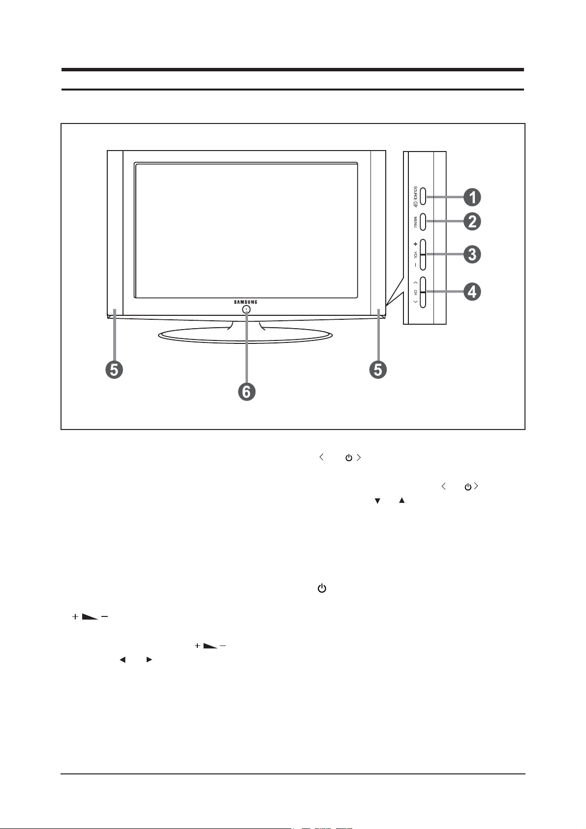
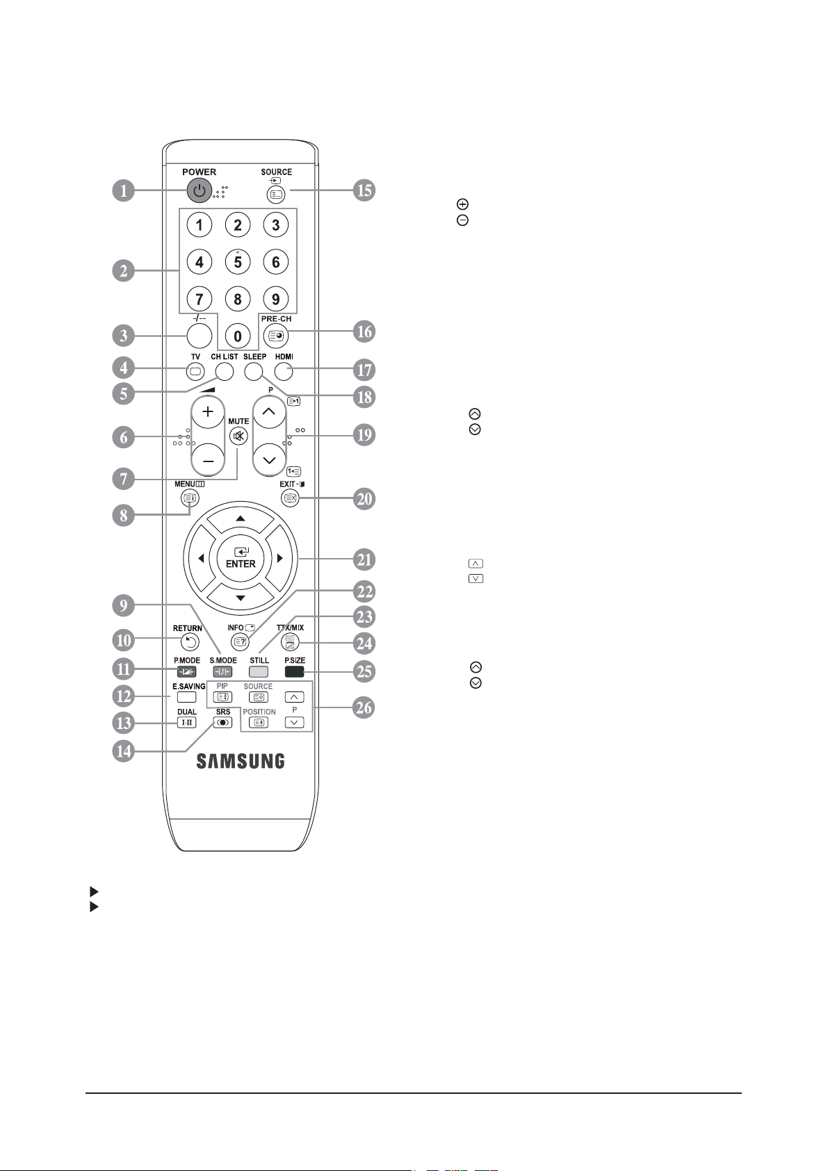
10 Operating Instructions and Installation
10-1
10 Operating Instructions and Installation
10-1 Front
1. SOURCE
Toggles between all the available input sources
(TV, Ext.1, Ext.2, AV, S-Video, Component, PC,
HDMI1, HDMI2).
In the on-screen menu, use this button as you use the
ENTER button on the remote control.
2. MENU
Press to see an on-screen menu of your TV's features.
In case of DTV mode, the DTV menu appears.
3.
Press to decrease or increase the volume.
In the on-screen menu, use the buttons as
you use the and buttons on the remote control.
4. C/P.
Press to change channels.
In the on-screen menu, use the C/P. buttons
as you use the and buttons on the remote control.
(Without the Remote Control, you can turn on the TV
by using the Channel buttons.)
5. Speakers
6. (Power)
Press to turn the TV on and off.
Power Indicator
and turns off when the power is on and lights up
in stand-by mode. Remote Control Sensor Aim the
remote control towards this spot on the TV.
Remote Control Sensor
Aim the remote control towards this spot on
the TV.
- The product colour and shape may vary depending on the model.
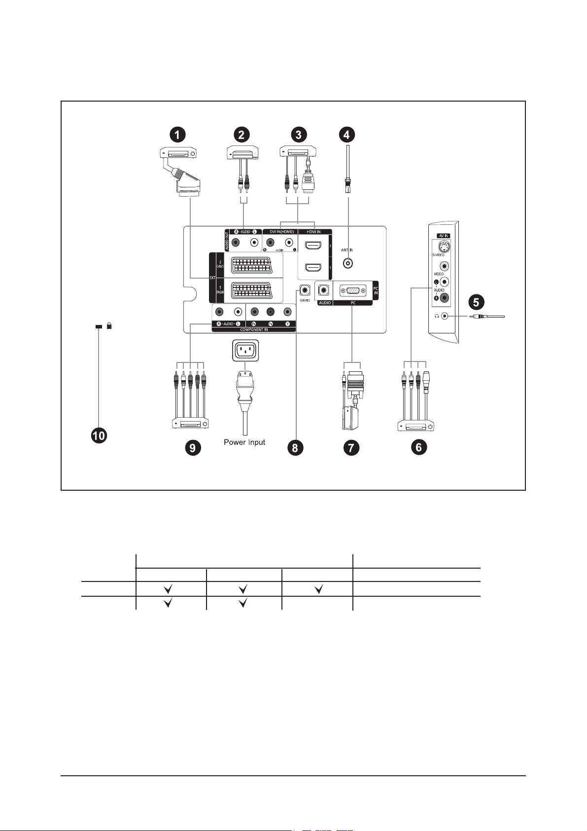
10-2 Connection Panel
10 Operating Instructions and Installation
10-2
- Whenever you connect an external device to your TV, make sure that power on the unit is turned off.
- When connecting an external device, match the colour of the connection terminal to the cable.
1. Connecting Set-Top Box, VCR or DVD
- Inputs or outputs for external devices, such as VCR, DVD, video game device or video disc players.
Connector
EXT 1
EXT 2
Output
Video + Audio (L/R)
Only TV or DTV output is available.
Output you can choose.
Input
Video Audio (L/R) RGB
10 Operating Instructions and Installation
10-3
2. Connecting AUDIO
Connect RCA audio cables to "R - AUDIO - L" on the rear of your set and the other ends to corresponding audio in
connectors on the Amplifier or DVD Home Theater.
3. HDMI IN 1, HDMI IN 2
- Supports connections between HDMI-connection-enabled AV devices (Set-Top Boxes, DVD players).
- No additional Audio connection is needed for an HDMI to HDMI connection.
What is HDMI?
- "High Definition Multimedia interface" allows the transmission of high definition digital video data and
multiple channels of digital audio ( 5.1 channels).
- The HDMI/DVI terminal supports DVI connection to an extended device with the appropriate cable
(not supplied). The difference between HDMI and DVI is that the HDMI device is smaller in size, has the
HDCP (High Bandwidth Digital Copy Protection) coding feature installed, and supports multi - channel
digital audio.
DVI IN (HDMI IN 2) / (AUDIO R/L)
- When connecting this product via HDMI or DVI to a Set Top Box, DVD Player or Games Console etc, make sure
that it has been set to a compatible video output mode as shown in the table below. Failure to observe this may
result in picture distortion, image breakup or no picture.
- When using an HDMI/DVI cable connection, it is only possible from the HDMI 2 IN terminal.
You should use the DVI-to-HDMI cable or DVI-HDMI Adapter for the connection, and the "R- AUDIO - L"
terminal on DVI for sound output.
Supported modes for HDMI/DVI and Component
4. Connecting an Aerial or Cable Television Network
To view television channels correctly, a signal must be received by the set from one of the following sources:
- An outdoor aerial / A cable television network / A satellite network
6. Connecting External A/V Devices
- Connect RCA or S-VIDEO cable to an appropriate external A/V device such as VCR, DVD or Camcorder.
- Connect RCA audio cables to "R - AUDIO - L" on the rear of your set and the other ends to corresponding audio
out connectors on the A/V device.
- Headphone may be connected to the headphone output ( 5 ) on the rear of your set. While the headphone is
connected, the sound from the built-in speakers will be disabled.
7. Connecting Computer
- Connect the D- Sub cable (optional) to "PC (PC IN)" on the rear of your set and the other end to the Video Card of
your computer.
- Connect the stereo audio cable (optional) to "AUDIO (PC IN)" on the rear of your set and the other end to "Audio
Out" of the sound card on your computer.
8. SERVICE
- Service connection for qualified service engineer.
9. Connecting Component Devices (DTV/DVD)
- Connect component video cables (optional) to component connector ("P
R", "PB", "Y") on the rear of your set and
the other ends to corresponding component video out connectors on the DTV or DVD.
- If you wish to connect both the Set-Top Box and DTV (or DVD), you should connect the Set-Top Box to the DTV
(or DVD) and connect the DTV (or DVD) to component connector ("P
R", "PB", "Y") on your set.
- The PR, PB and Y connectors on your component devices (DTV or DVD) are sometimes labeled Y, B-Y and R-Y
or Y, Cb and Cr.
- Connect RCA audio cables (optional) to "R - AUDIO - L" on the rear of your set and the other ends to
corresponding audio out connectors on the DTV or DVD.
- This LCD TV displays its optimum picture resolution in 720p mode.
- This LCD TV displays its maximum picture resolution in 1 080i mode.
10. Kensington Lock
- The Kensington lock (optional) is a device used to physically fix the system when used in a public place.
- If you want to use a locking device, contact the dealer where you purchased the TV.
- The place of the Kensington Lock may be different depending on its model.
480i 480p 576i 576p 720p 1080i
HDMI/DVI 50Hz X X X O O O
HDMI/DVI 60Hz X O X X O O
Component O O O O O O
10 Operating Instructions and Installation
10-4
The performance of the remote control may be affected by bright light.
This is a special remote contro for the visually impaired, and has Braille points on the Power, Channel
and Volume buttons.
10-3 Remote Control
1. Television Standby button
2. Number buttons for direct channel access
3. One/Two-digit channel selection
4. Selects the TV mode directly
5. Used to display Channel Lists on the screen.
6. Volume increase
Volume decrease
7. Temporary sound switch-off
8. Menu display and change confirmation
9. Sound mode selection
10.Returns to the previous menu.
11.Picture effect selection
12.Adjusts screen brightness to save energy.
13.Sound effect selection
14.SRS TSXT selection
15.Available source selection
16.Previous channel
17.Selects the HDMI mode directly.
18.omatic Power-off
19.P : Next channel
P : Previous channel
20.Exit the OSD
21.Control the cursor in the menu
22.
Use to see information on the current broadcast
23.Picture freeze
25.Picture size selection
26.PIP:Picture-In-Picture On / Off
SOURCE: Input source selection
POSITION: PIP position selection
P : Next channel
P : Previous channel
Tteletext Functions
4. Exit from the teletext display
8. Teletext index
15.Teletext mode selection (LIST/FLOF)
16.Teletext sub pag
19.P : Teletext next page
P : Teletext previous page
20.Teletext cancel
22.Teletext reveal
24.Alternately select Teletext, Double, or Mix.
9. 11. 23. 25 Fastext topic selection
26.PIP: Teletext Hold
SOURCE: Teletext Store
POSITION: Teletext size selection
10 Operating Instructions and Installation
10-5
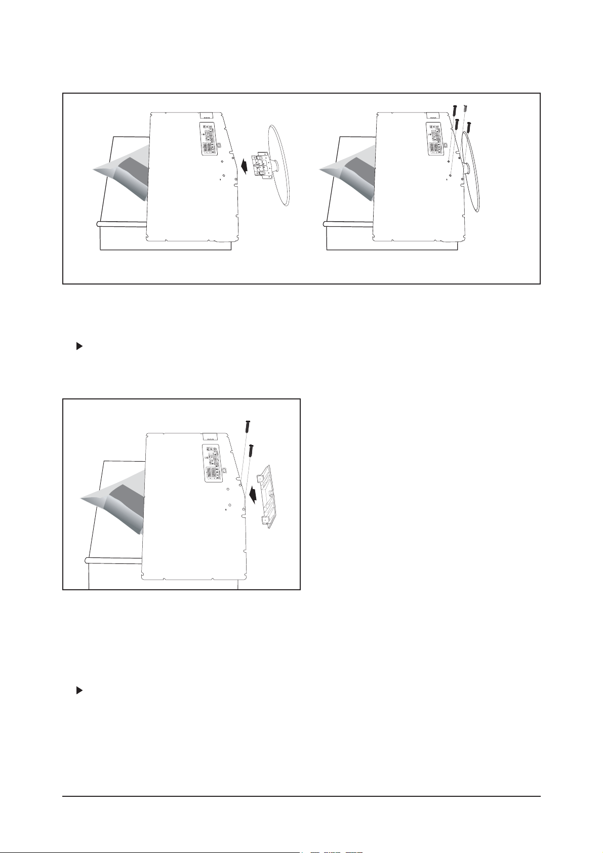
10-4 Installing the Stand
1. Place the TV fdown on a soft cloth or cushion on a table.
2. Put the stand into the hole at the bottom of the TV.
3. Insert screw into the hole indicated and tighten.
The stand is installed for models with the screen size of 40 inch and above.
10-5 Installing the Wall Mount Kit
Wall mount items (sold separately) allow you to mount the TV on the wall.
For detailed information on installing the wall mount, see the instructions provided with the Wall Mount
items. Contact a technician for assistance when installing the wall mounted bracket.
Samsung Electronics is not responsible for any damage to the product or injury to yourself or others if you
elect to install the TV on your own.
Remove the stand and cover the bottom hole with a cap and fasten with two screws.
<2> <3>

Memo
10 Operating Instructions and Installation
10-6
11 Disassembly and Reassembly
11-1
11 Disassembly and Reassembly
This section of the service manual describes the disassembly and reassembly procedures for the TFT-LCD
TV.
WARNING : This monitor contains electrostatically sensitive devices. Use caution when
handling these components.
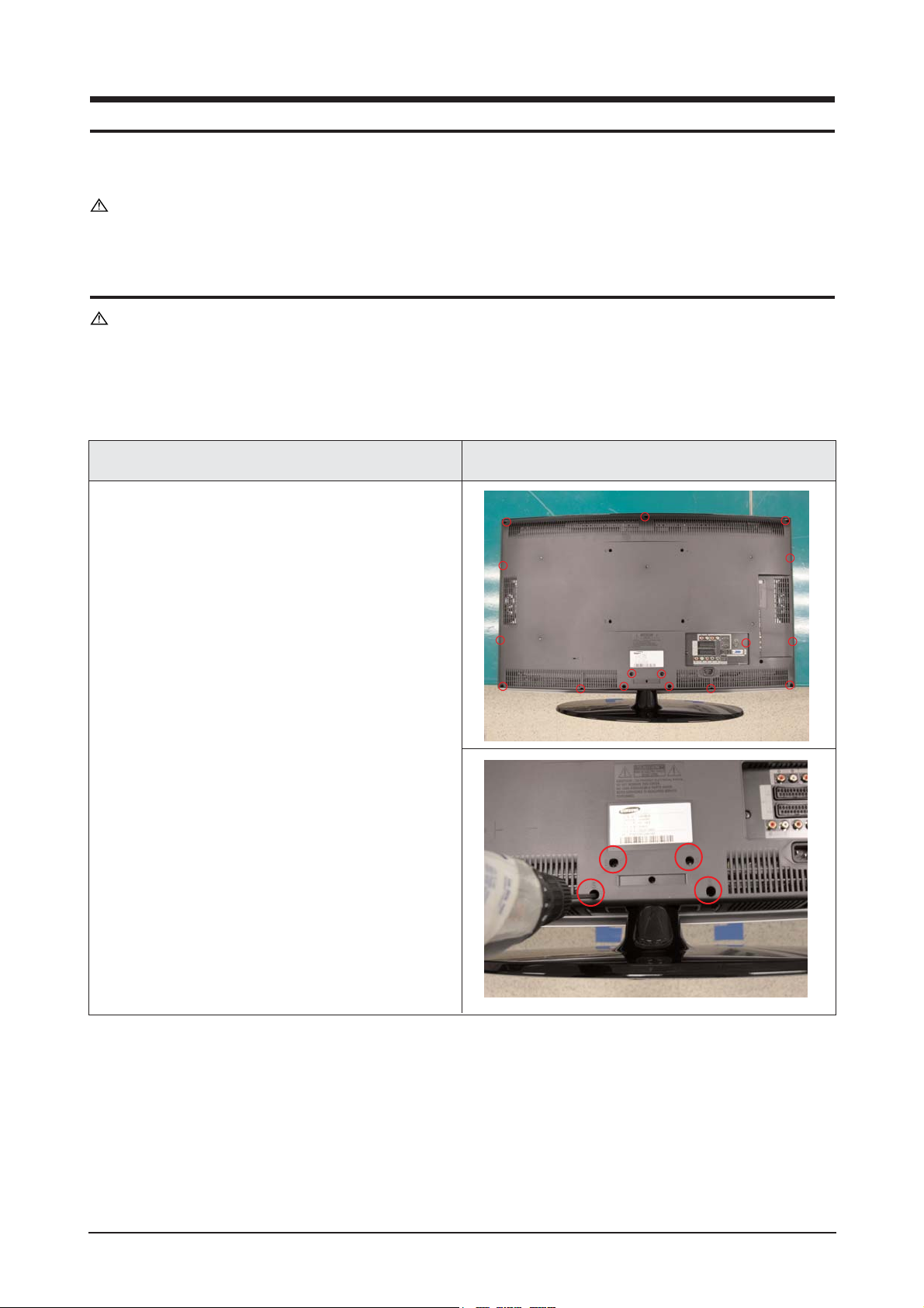
11-1 Disassembly
Cautions : 1. Disconnect the monitor from the power source before disassembly.
2. Follow these directions carefully; never use metal instruments to pry apart the
cabinet.
Description Picture Description
1. Place monitor face down on cushioned table.
Remove screws from the rear cover.
Remove screws from the stand.
11 Disassembly and Reassembly
11-2
3. Remove Screws from the stand BRKT and lift
up the stand BRKT.
Description Picture Description
2. Lift up the rear cover and remove the stand.
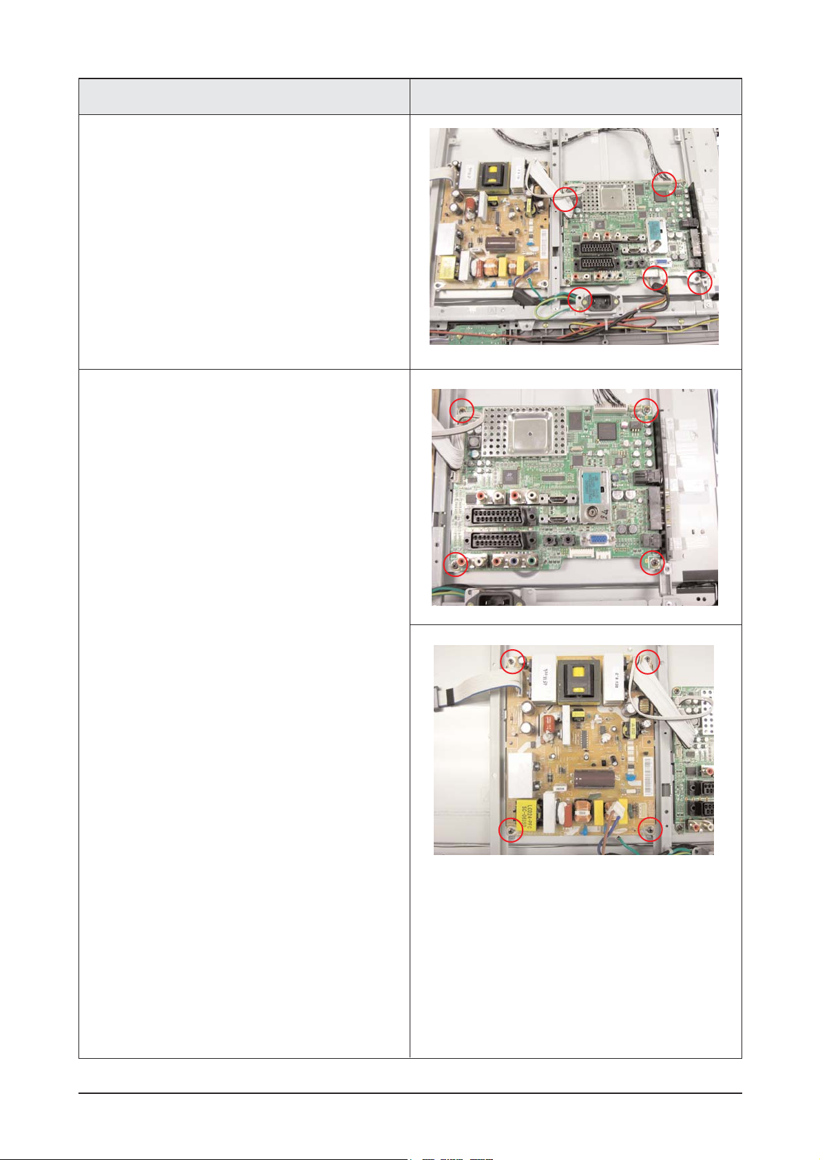
11 Disassembly and Reassembly
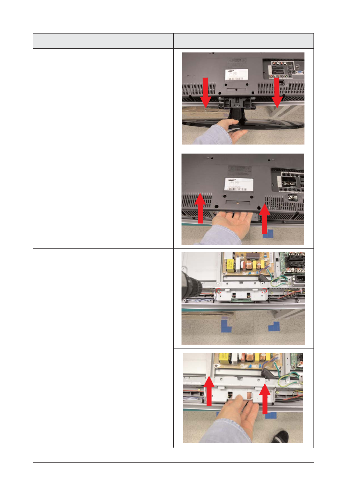
11-3
5. Remove screws from the boards and lift up the
boards.
Description Picture Description
4. Disonnect cable from the boards.
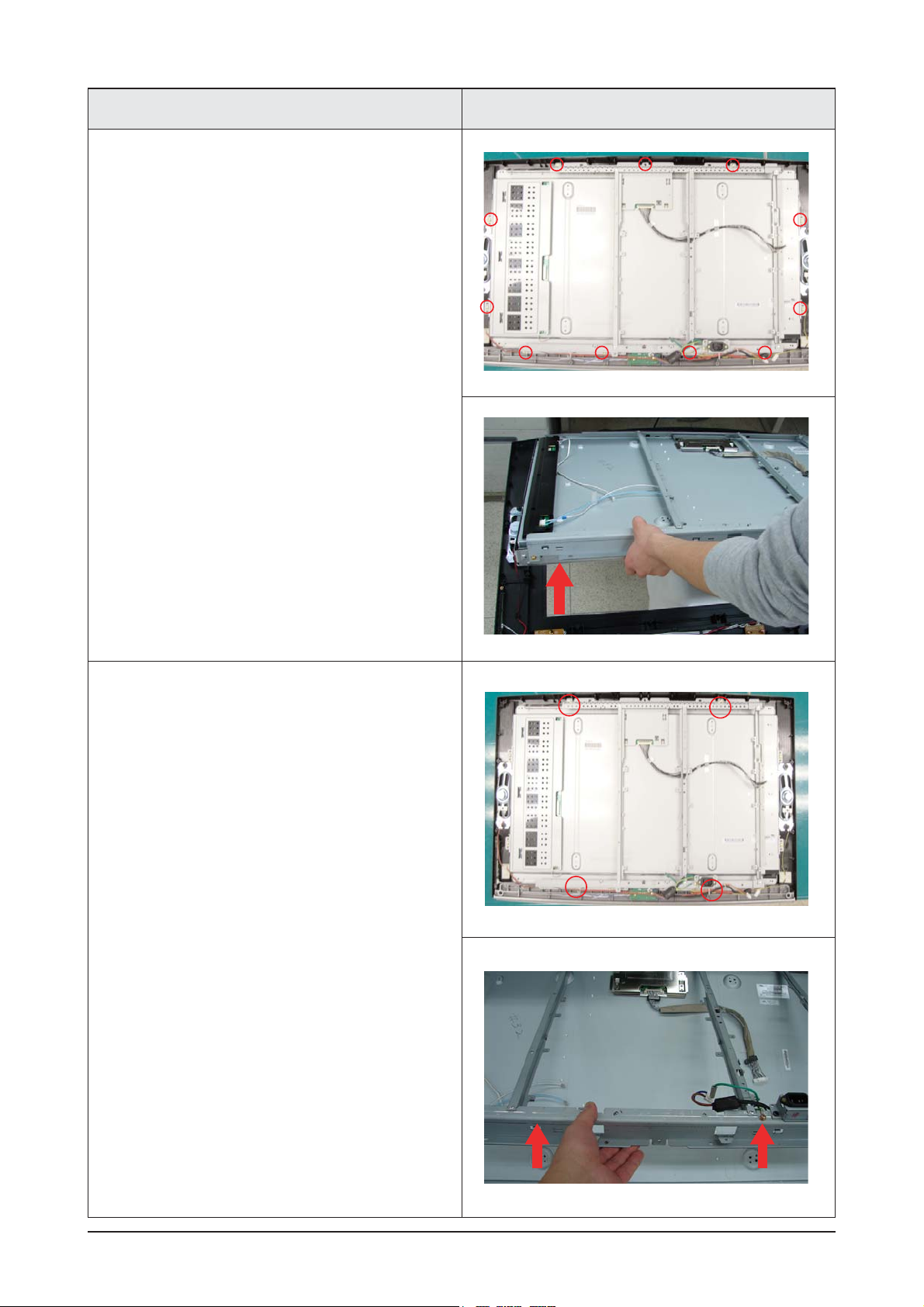
11 Disassembly and Reassembly
11-4
7. Remove 5 secews from the BRKT.
Lift up the BRKT.
Description Description Picture
6. Remove screws and Lift up the Lcd panel.
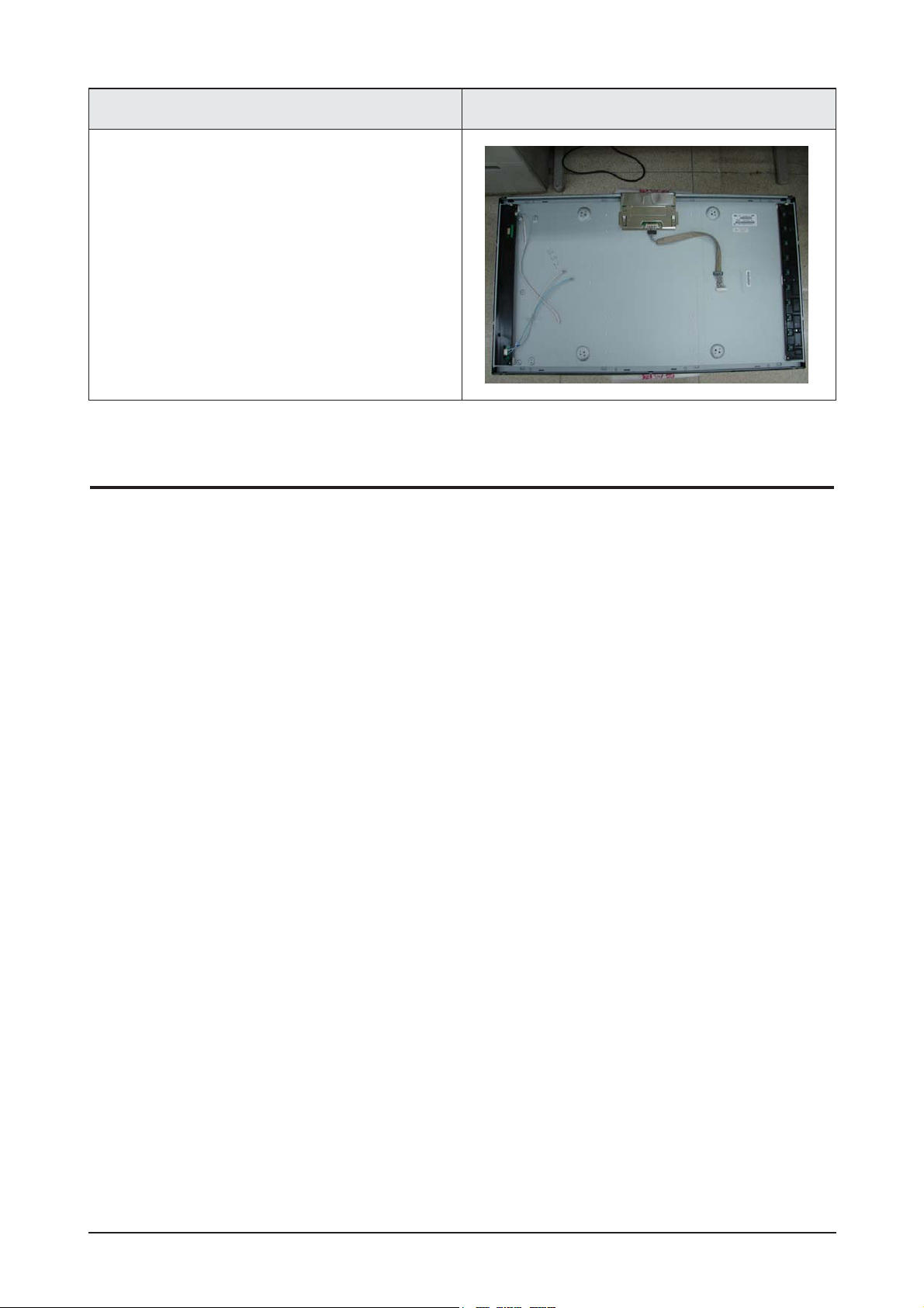
11 Disassembly and Reassembly
11-5
Description Description Picture
11-2 Reassembly
Reassembly procedures are in the reverse order of disassembly procedures.

11 Disassembly and Reassembly
11-6
Memo
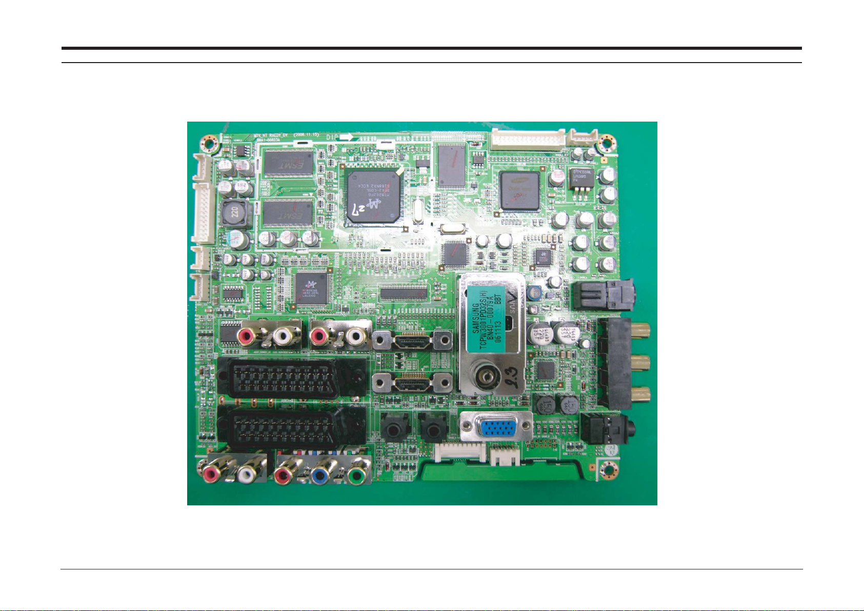
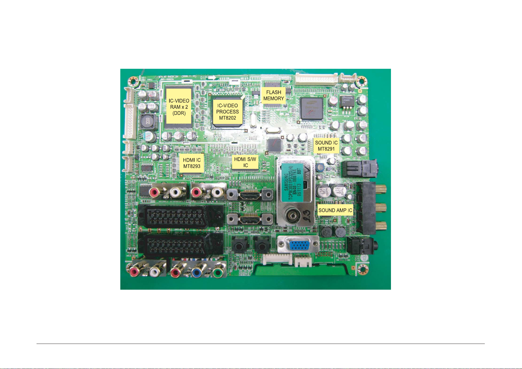
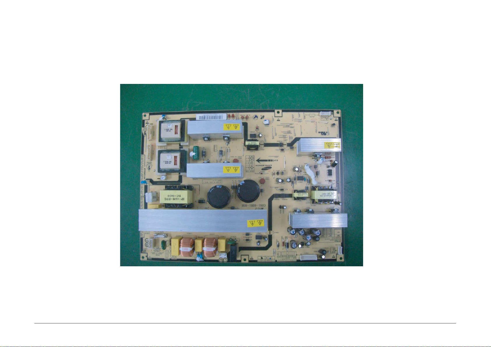
12 PCB Diagram
12-1
12 PCB Diagram
12-1-1 26", 32", 37", 40", 46" Main PCB Diagram
12 PCB Diagram
12-2
12-2-2 26", 32", 37", 40", 46" Main PCB Diagram
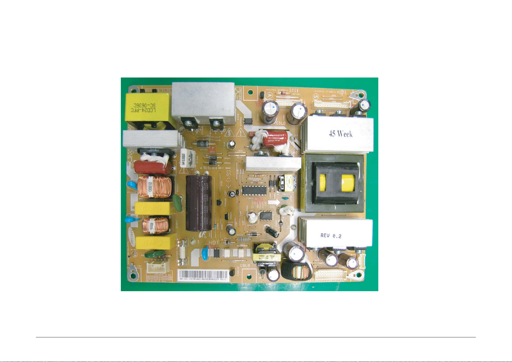
12 PCB Diagram
12-3
12-3 26, 32" SMPS
12 PCB Diagram
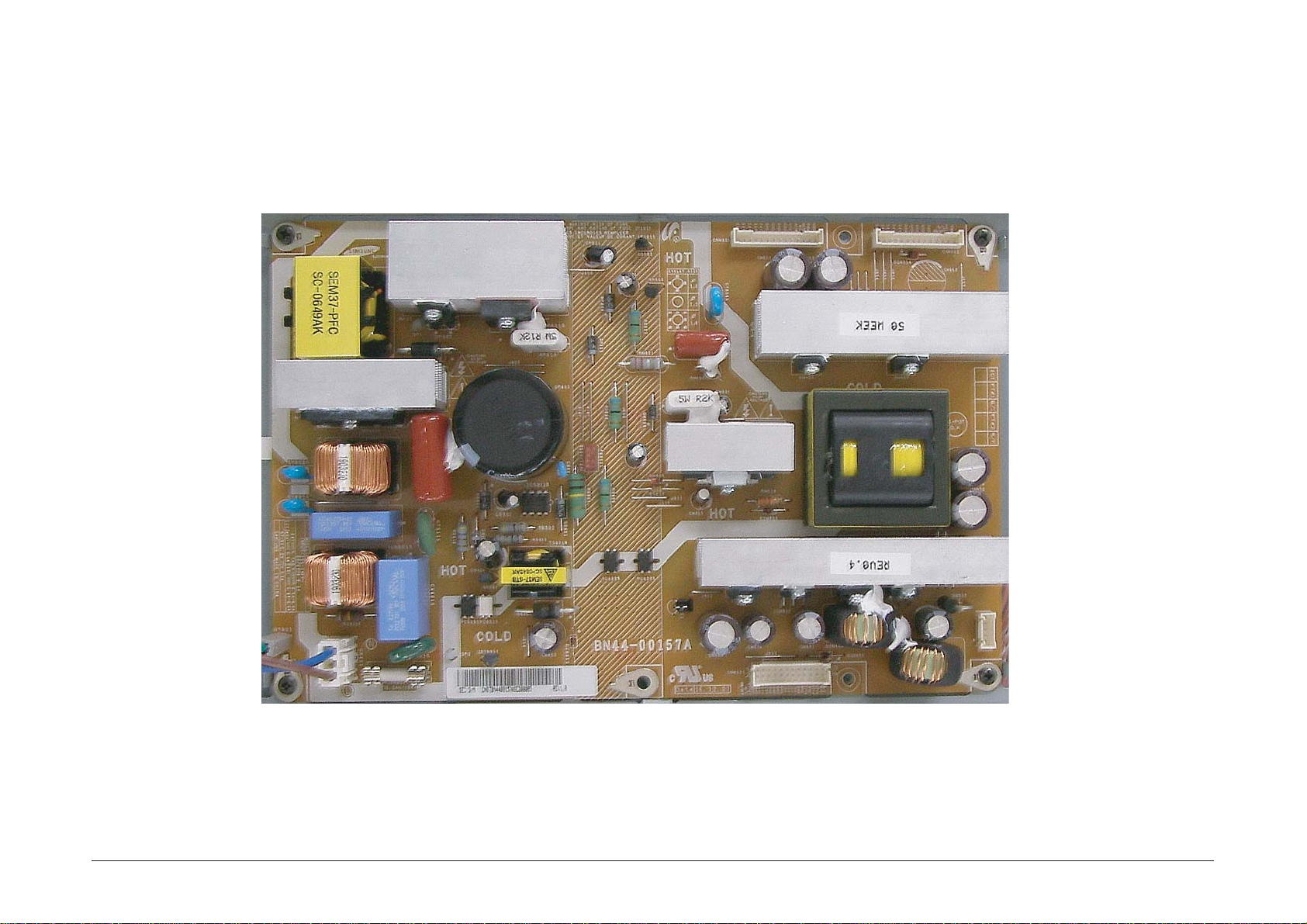
12-4
12-4 37" SMPS
12 PCB Diagram
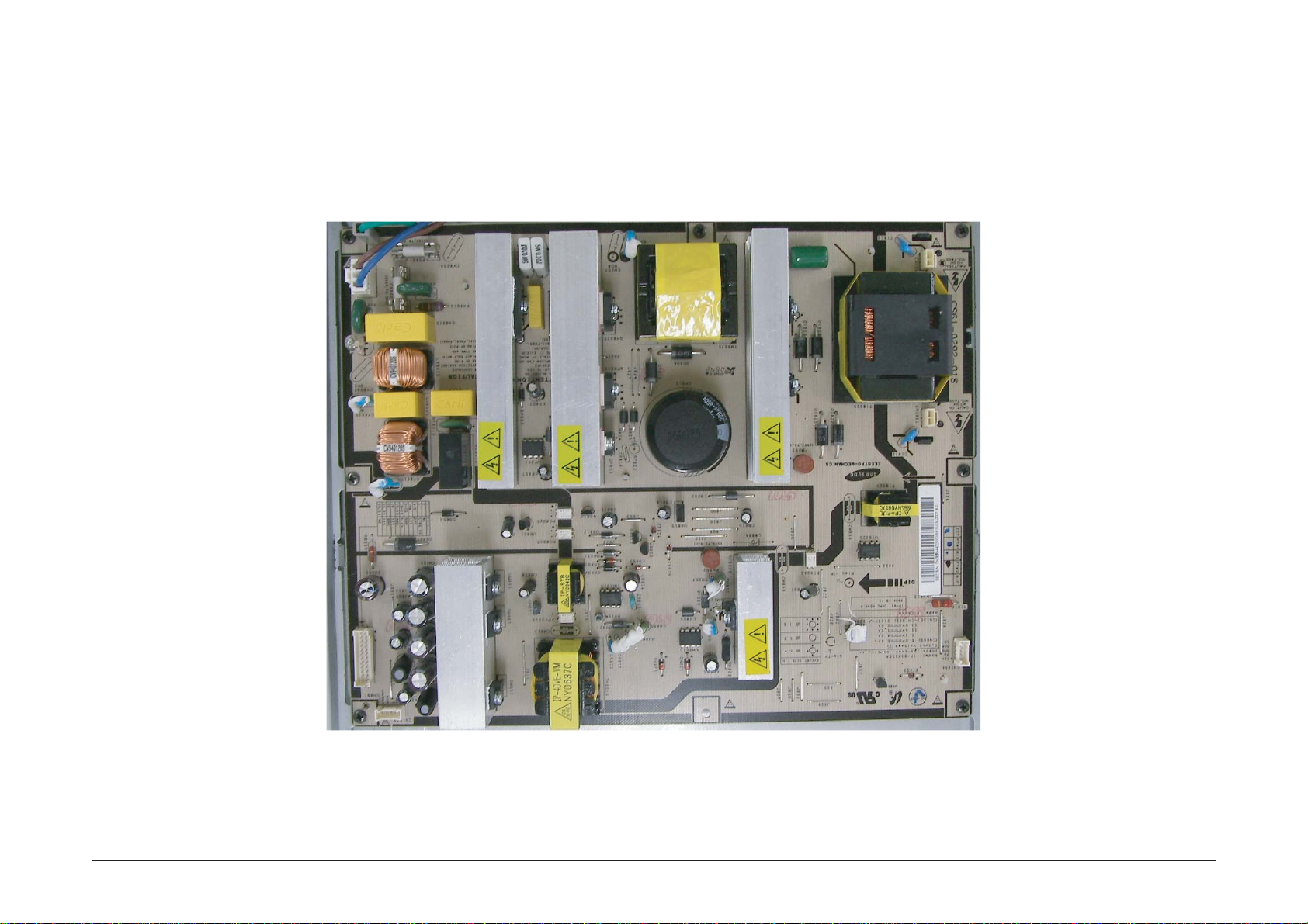
12-5
12-5 40" SMPS
12 PCB Diagram
12-6
12-6 46" SMPS
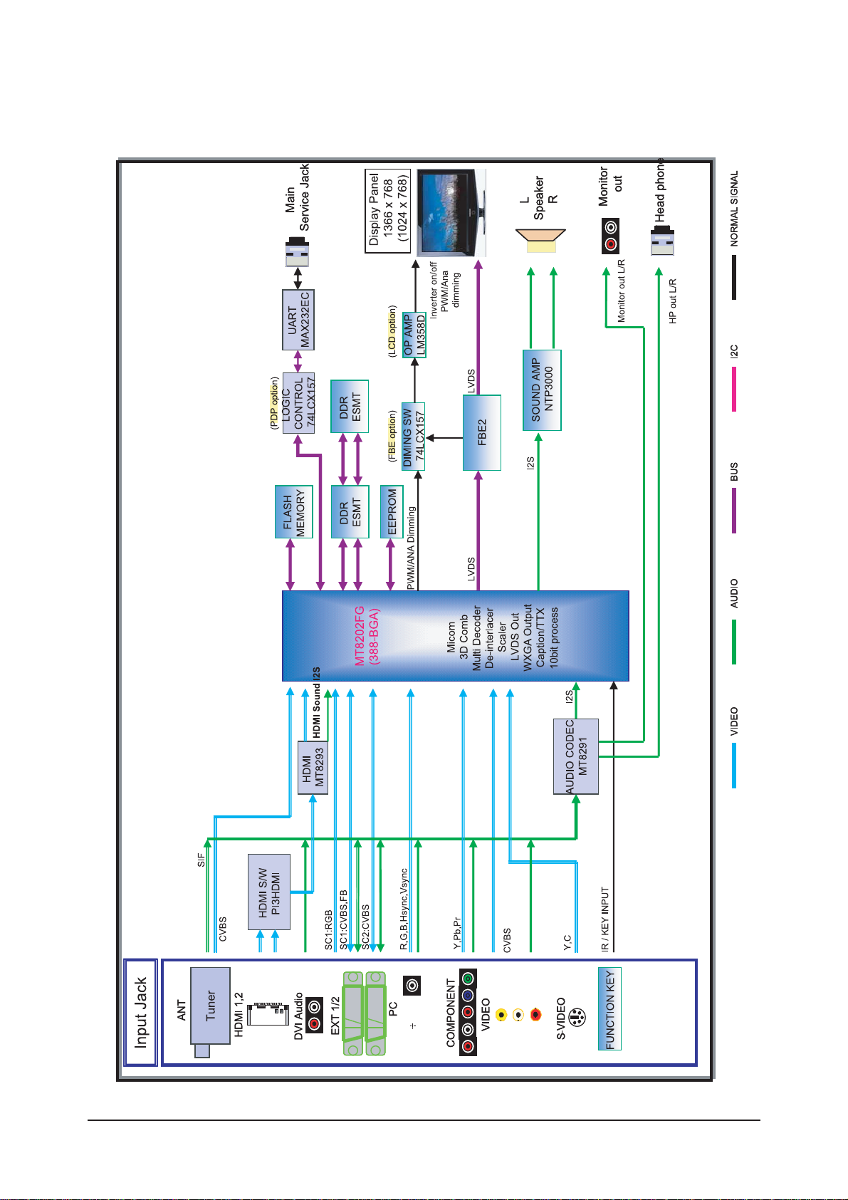
13 Circuit Descriptions
13-1
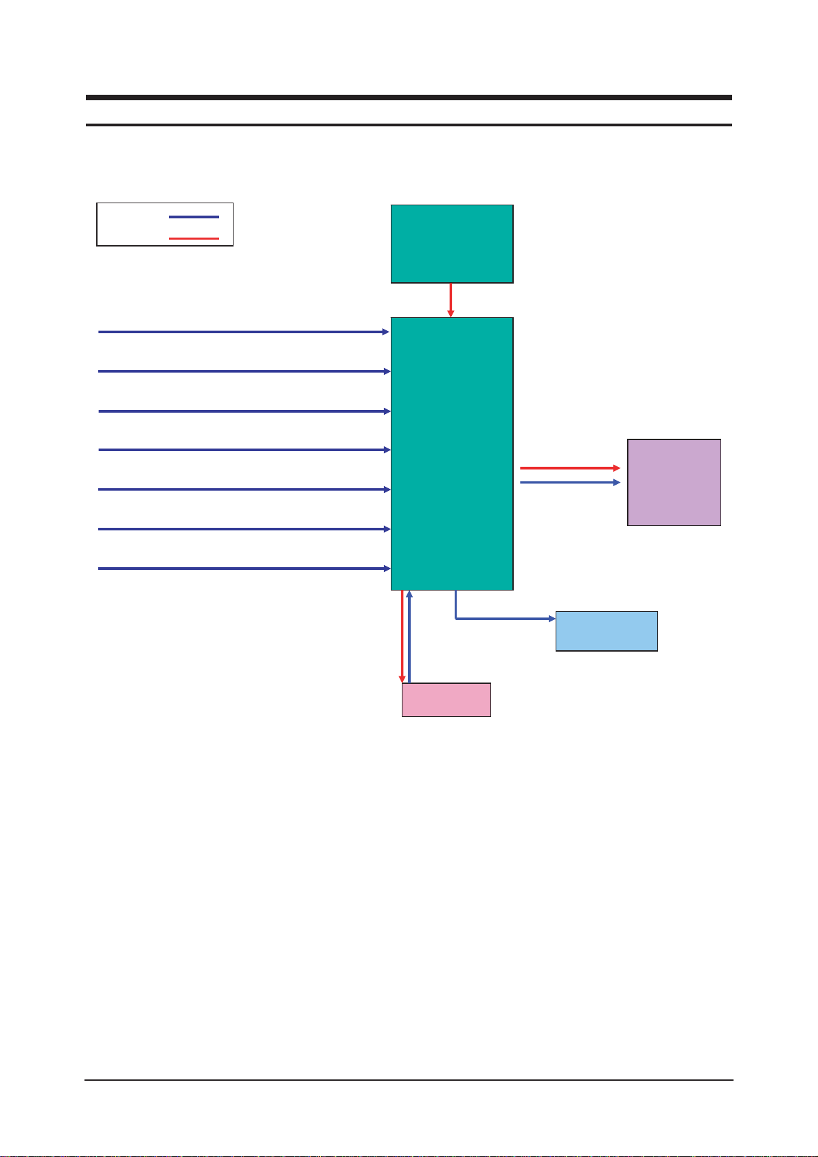
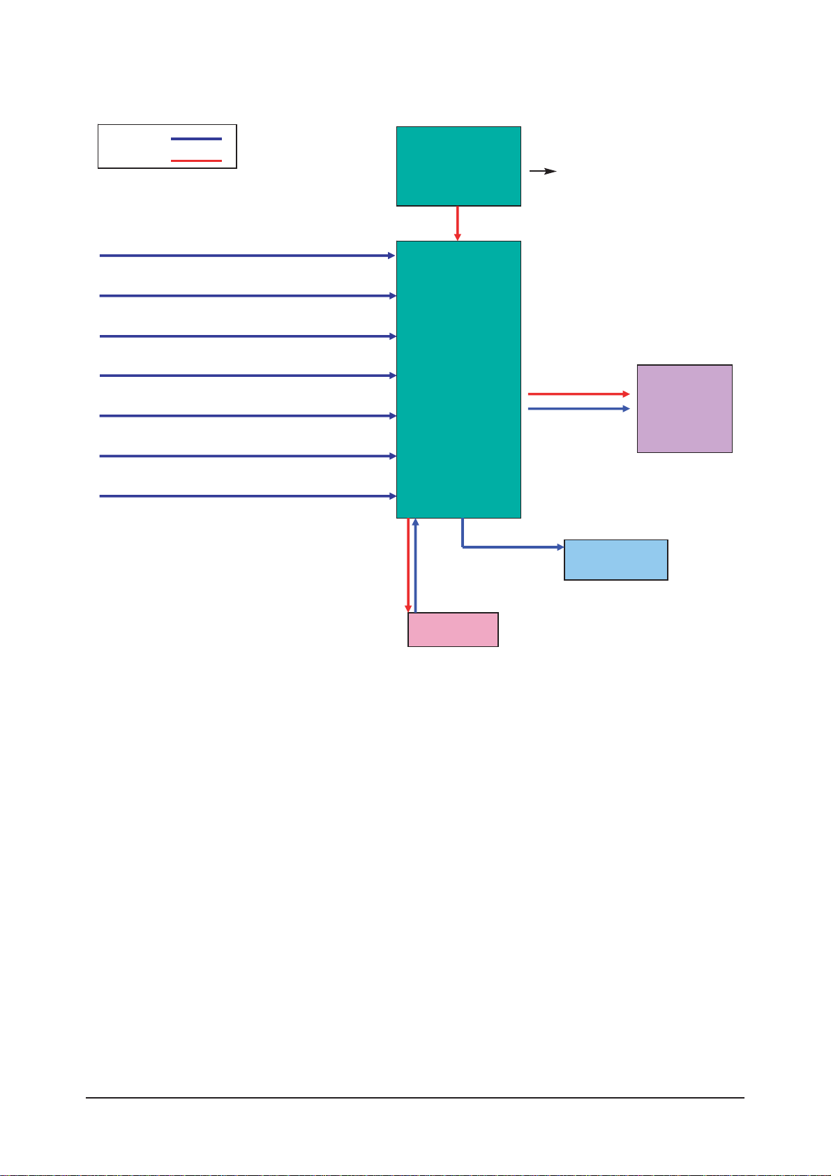
13 Circuit Descriptions
13-1 Block description
RF IN
Scart 1,2
A/V
S-Video
Component
HDMI 1, 2
PC
Main
Board
Panel
T-con
Board
Speaker
IR/LED
Signal
Power
Bordeaux consists of three main blocks
1. Main board : Video signal processing
2. IP board : Power supply & Inverter
3. T-con board : LCD Panel control
IP Board
13 Circuit Descriptions
13-2
Bordeaux consists of three main blocks
1. Main board : Video signal processing
2. SMPS : Power supply
3. T-con board : LCD Panel control
SMPS
INVERTER
RF IN
Scart 1,2
A/V
S-Video
Component
HDMI 1, 2
Main
Board
Panel
T-con
Board
Speaker
IR/LED
Signal
Power
PC
13 Circuit Descriptions
13-3
13-2 Main Block
13 Circuit Descriptions
13-4
13-3 SMPS Board
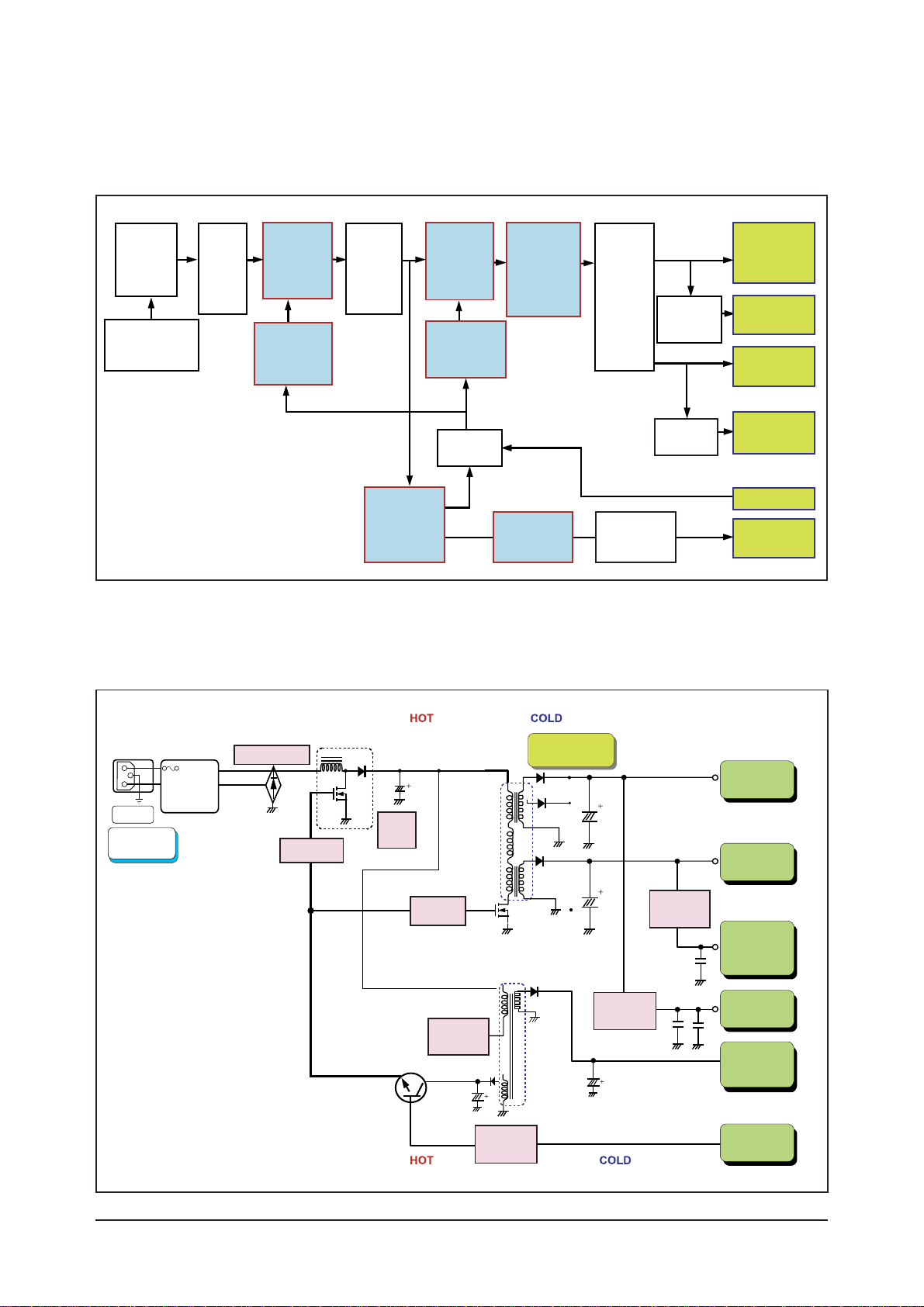
13-3-1 26", 32" Power Block
13-3-2 26", 32" SMPS Diagram
Line
Filter
Part
PFC
Switching
Part
Resonance
Switching
Part
Resonance
Transformer
Output
Rectifier
Part
DC/DC
SI-8008HFE
or AP1501A
Inverter
SMPS
24V
Signal
5.3V
Signal
13V
Sound
12V
Stand-By
5.2V
Regulator
KA278R12
Resonance
Controller
MC33067
PFC
Controler
TDA4863
Stand-By
Controller
STR-A6159
AC Input
(90Vac~264Vac)
AC
Rectifier
PFC
Rectifier
On/Off
Control
On/Off
EMI
FILTER
AC Input
90V~264V
INPUT
Rectifier
MC33067
STR-A6159
Current
Resonant Type
450V
150uF
TDA4863
PFC DC
Output
Trans EER4445
Trans EE2020
PFC
Regulator
Sound
+12V
V5D
+5.3V
Stand-By
5.2V
INVERTER
24V
Main
+13V
DC/DC
Converter
On/Off
Control
Power On/Off
Signal
ST-BY
Transformer
Output
Rectifier
Part
13 Circuit Descriptions
13-5
Output
Name
Output Voltage Output Current
Load Characteristics PCB Loc.
Usage Remark
Normal
24.5V
5.3V
12.7V
9.2V
8.0V
0.1V
0.1V
0.01V
0.01V
0.1V
4.0V
5.0V
0.5V
1.1V
0.6V
Pulsating Main B'D Drive -
-
-
-
-
Sound
Stand-by
Drive, Logic,
Buffer,
Image Digital
Image Analog
Main B'D
Main B'D
Main B'D
Main B'D
Constant
Constant
Constant
Constant
3.0V
3.0V
0.3V
0.3V
0.3V
23.52V
~25.48V
5.13V
~5.67V
11.9V
~13.7V
8.83V
~9.57V
5.58V
~8.5V
4
5
7
4
5
Min Typical PeakRegulation(%) Variable Range
24V
13V
Vamp
ST-BY
5.3V
13 Circuit Descriptions
13-6
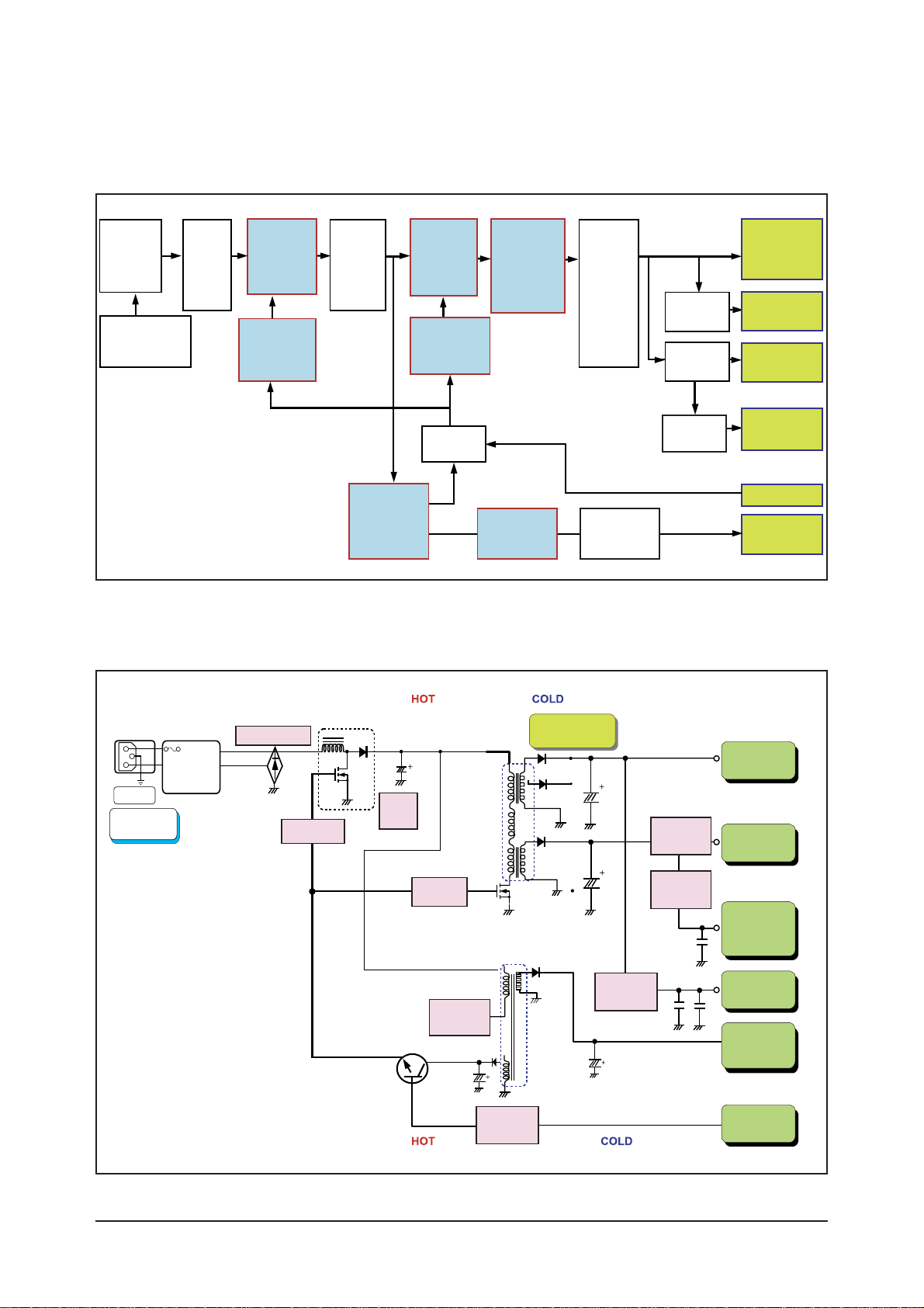
13-3-5 37" Power Block
13-3-6 37" SMPS Diagram
Line
Filter
Part
PFC
Switching
Part
Resonance
Switching
Part
Resonance
Transformer
Output
Rectifier
Part
DC/DC
MC33167
DC/DC
LM2576
Inverter
SMPS
24V
Signal
5.3V
Signal
13V
Sound
12V
Stand-By
5.2V
Regulator
KA278R12
Resonance
Controller
F9222L
PFC
Controler
TDA4863
Stand-By
Controller
Viper22A
AC Input
(90Vac~264Vac)
AC
Rectifier
PFC
Rectifier
On/Off
Control
On/Off
EMI
FILTER
AC Input
90V~264V
INPUT
Rectifier
F9222L
Viper22A
Current
Resonant Type
450V
150uF
TDA4863
PFC DC
Output
Trans EER4445
Trans EE2020
PFC
Regulator
DC/DC
Converter
Sound
+12V / +9V
V5D
+5.3V
Stand-By
5.2V
INVERTER
24V
Main
+13V
DC/DC
Converter
On/Off
Control
Power On/Off
Signal
ST-BY
Transformer
Output
Rectifier
Part
13 Circuit Descriptions
13-7
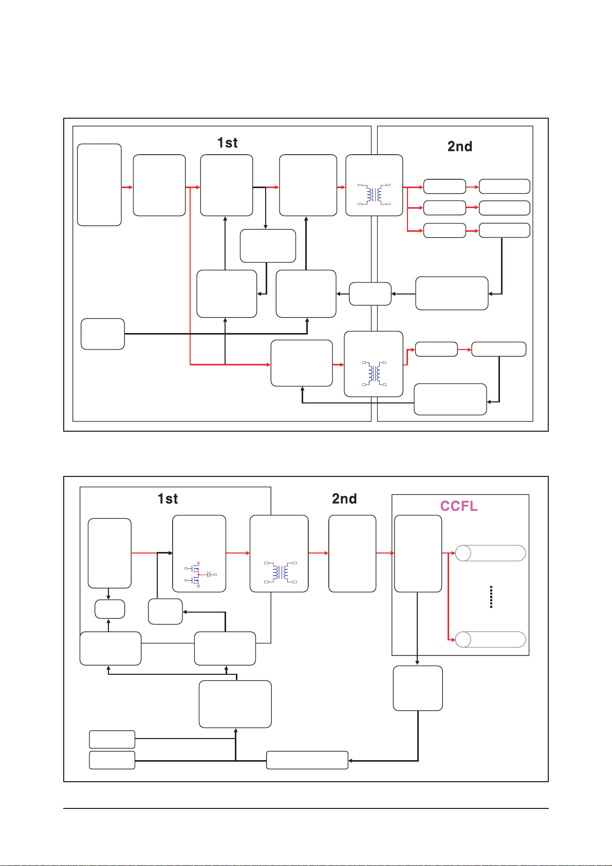
13-3-7 40, 46" IP Board
13-3-8 40, 46" IP Board
Power
Input
(AC90V
~264V)
EMI Filter
Rectifier
Rectifier
Feedback
Protection
Feedback
Protection
Feedback
Protection
FWM
CONTROLLER
Stand-by
CONTROLLER
(Switch)
FWM
CONTROLLER
VCC
On/Off
Opto-
coupler
13.0V / 0.4A
12.0V / 2.5A
5.4V / 43.5A
6.2V / 0.4A
Rectifier
Rectifier
Rectifier
SWITCHING
TRANSFORMER
TRANSFORMER
RFC
(switching,
Inductor)
Power
Input
(380V)
2
nd
Resonant
Balance
Board
Voltage /
Current /
LAMP /
Detection
LAMP
LAMP
SWITCHING
Feedback
CONTROLLER
Opto-Coupler
UVLO
Gate
DRIVE
Opto-Coupler /
Pulse-
Transformer
ON/OFF
DIM
TRANSFORMER
 Loading...