

Samsung LE26S81BHX Schematic
TFT-LCD TV
Chassis Model
GJA26TSA LE26S81BHX
GJA32TSA LE32S81BHX
GJA37TSA LE37S81BHX
GJA40TSA LE40S81BHX
GJA46TSA LE46S81BHX
Manual
SERVICE
TFT-LCD TV Fashion Feature
- Luxurious Slim Design
- Supreme Picture Quality
- Supreme Sound Quality
- Supreme Convenience Quality
- Convenience for Users

ii
Copyright
2007 by Samsung Electronics Co., Ltd.
All rights reserved.
This manual may not, in whole or in part, be copied,
photocopied, reproduced, translated, or converted to any
electronic or machine readable form without prior
written permission of Samsung Electronics Co., Ltd.
LE26S81BH/LE32S81BH/LE37S81BH/LE40S81BH/
LE46S81BH Service Manual
First edition Oct 2007.
Printed in Korea.
Trademarks
Samsung is the registered trademark of Samsung
Electronics Co., Ltd.
LE26S81BH/LE32S81BH/LE37S81BH/LE40S81BH/
LE46S81BH and Macmaster Cable Adapter are
trademarks of Samsung Electronics Co., Ltd.
Macintosh and Power Macintosh are trademarks of
Apple Computer, Inc.
All other trademarks are the property of their respective
owners.
Contents
Contents
©2007 Samsung Electronics Co.,Ltd.
All rights reserved.
Printed in Korea
P/N : BN82-00184A-00
This Service Manual is a property of Samsung
Electronics Co.,Ltd.
Any unauthorized use of Manual can be punished under
applicable International and/or domestic law.
Area
GSPN(Global Service Partner Network)
North America
Latin America
CIS
Europe
China
Asia
Mideast & Africa
http://service.samsungportal.com
http://latin.samsungportal.com
http://cis.samsungportal.com
http://europe.samsungportal.com
http://china.samsungportal.com
http://asia.samsungportal.com
http://mea.samsungportal.com
Web Site
1 Precautions
1-1
1-1-1 Warnings
1. For continued safety, do not attempt to modify the
circuit board.
2. Disconnect the AC power and DC Power Jack before
servicing.
1-1-2 Ser vicing the LCD Monitor
1. When servicing the LCD Monitor Disconnect the AC
line cord from the AC outlet.
2. It is essential that service technicians have an accurate
voltage meter available at all times. Check the
calibration of this meter periodically.
1-1-3 Fire and Shock Hazard
Before returning the monitor to the user, perform the
following safety checks:
1. Inspect each lead dress to make certain that the leads
are not pinched or that hardware is not lodged between
the chassis and other metal parts in the monitor.
2. Inspect all protective devices such as nonmetallic
control knobs, insulating materials, cabinet backs,
adjustment and compartment covers or shields,
isolation resistor-capacitor networks, mechanical
insulators, etc.
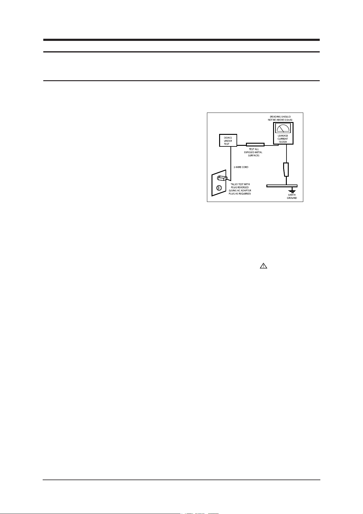
3. Leakage Current Hot Check (Figure 1-1):
WARNING: Do not use an isolation
transformer during
this test.
Use a leakage current tester or a metering system that
complies with American National Standards Institute
(ANSI C101.1, Leakage Current for Appliances), and
Underwriters Laboratories (UL Publication UL1410,
59.7).
Figure 1-1. Leakage Current Test Circuit
1-1-4 Product Safety Notices
Some electrical and mechanical parts have special
safety-related characteristics which are often not evident
from visual inspection. The protection they give may not
be obtained by replacing them with components rated for
higher voltage, wattage, etc. Parts that have special safety
characteristics are identified by on schematics and parts
lists. A substitute replacement that does not have the same
safety characteristics as the recommended replacement part
might create shock, fire and/or other hazards. Product
safety is under review continuously and new instructions
are issued whenever appropriate.
1 Precautions
Follow these safety, servicing and ESD precautions to prevent damage and to protect against potential hazards such as electrical shock.
1-1 Safety Precautions

1 Precautions
1-2
1-2-1 General Ser vicing
Precautions
1. Always unplug the units AC power cord from the AC
power source and disconnect the DC Power Jack
before attempting to:
(a) remove or reinstall any component or assembly, (b)
disconnect PCB plugs or connectors, (c) connect a test
component in parallel with an electrolytic capacitor.
2. Some components are raised above the printed circuit
board for safety. An insulation tube or tape is
sometimes used. The internal wiring is sometimes
clamped to prevent contact with thermally hot
components. Reinstall all such elements to their
original position.
3. After servicing, always check that the screws,
components and wiring have been correctly
reinstalled. Make sure that the area around the
serviced part has not been damaged.
1. Immediately before handling any semiconductor
components or assemblies, drain the electrostatic
charge from your body by touching a known earth
ground. Alternatively, wear a discharging wrist-strap
device. To avoid a shock hazard, be sure to remove the
wrist strap before applying power to the monitor.
2. After removing an ESD-equipped assembly, place it
on a conductive surface such as aluminum foil to
prevent accumulation of an electrostatic charge.
3. Do not use freon-propelled chemicals. These can
generate electrical charges sufficient to damage ESDs.
4. Use only a grounded-tip soldering iron to solder or
desolder ESDs.
5. Use only an anti-static solder removal device. Some
solder removal devices not classified as anti-static
can generate electrical charges sufficient to damage
ESDs.
4. Check the insulation between the blades of the AC
plug and accessible conductive parts (examples: metal
panels, input terminals and earphone jacks).
5. Insulation Checking Procedure: Disconnect the power
cord from the AC source and turn the power switch
ON. Connect an insulation resistance meter (500 V) to
the blades of the AC plug.
The insulation resistance between each blade of the
AC plug and accessible conductive parts (see above)
should be greater than 1 megohm.
6. Always connect a test instruments ground lead to the
instrument chassis ground before connecting the
positive lead; always remove the instruments ground
lead last.
6. Do not remove a replacement ESD from its protective
package until you are ready to install it. Most
replacement ESDs are packaged with leads that are
electrically shorted together by conductive foam,
aluminum foil or other conductive materials.
7. Immediately before removing the protective material
from the leads of a replacement ESD, touch the
protective material to the chassis or circuit assembly
into which the device will be installed.
Caution: Be sure no power is applied to
the chassis or circuit and
observe all other safety
precautions.
8. Minimize body motions when handling unpackaged
replacement ESDs. Motions such as brushing clothes
together, or lifting your foot from a carpeted floor can
generate enough static electricity to damage an ESD.
1-3 Static Electricity Precautions
Some semiconductor (solid state) devices can be easily damaged by static electricity. Such components are commonly called
Electrostatically Sensitive Devices (ESD). Examples of typical ESD are integrated circuits and some field-effect transistors.
The following techniques will reduce the incidence of component damage caused by static electricity.
1-2 Ser vicing Precautions
WARNING: An electrolytic capacitor installed with the wrong polarity might explode.
Caution: Before servicing units covered by this service manual, read and follow the Safety
Precautions section of this manual.
Note: If unforeseen circumstances create conflict between the following servicing precautions and any of the safety
precautions, always follow the safety precautions.

1. For safety reasons, more than two people are
required for carrying the product.
2. Keep the power cord away from any heat emitting
devices, as a melted covering may cause fire or
electric shock.
3. Do not place the product in areas with poor
ventilation such as a bookshelf or closet. The
increased internal temperature may cause fire.
4. Bend the external antenna cable when connecting
it to the product. This is a measure to protect it
from being exposed to moisture. Otherwise, it
may cause a fire or electric shock.
5. Make sure to turn the power off and unplug the
power cord from the outlet before repositioning
the product. Also check the antenna cable or the
external connectors if they are fully unplugged.
Damage to the cord may cause fire or electric
shock.
6. Keep the antenna far away from any high-voltage
cables and install it firmly. Contact with the highvoltage cable or the antenna falling over may
cause fire or electric shock.
7. When installing the product, leave enough space
(10cm) between the product and the wall for
ventilation purposes.
A rise in temperature within the product may
cause fire.
1 Precautions
1-3
1-4 Installation Precautions

Memo
1 Precautions
1-4

2 Product Specifications
2-1
2 Product specifications
2-1 Fashion Feature
Supreme Digital Interface & Networking
-With a built-in HD digital tuner, it supports HD broadcasting with no particular set-top box and provides
simple access with a single remote control.
Excellent Picture Quality
-DNIe technology provides life-like clear images.
Dynamic Contrast
-Automatically detects the input visual signal and adjusts to create optimum contrast.
SRS TruSurround XT
-SRS TruSurround XT provides a virtual Dolby surround system.
Convenience
-The TV utilizes the HDMI system to implement perfect digital sound and picture quality.
±
° ° ° °
° ° ° °
2 Product Specifications
2-2
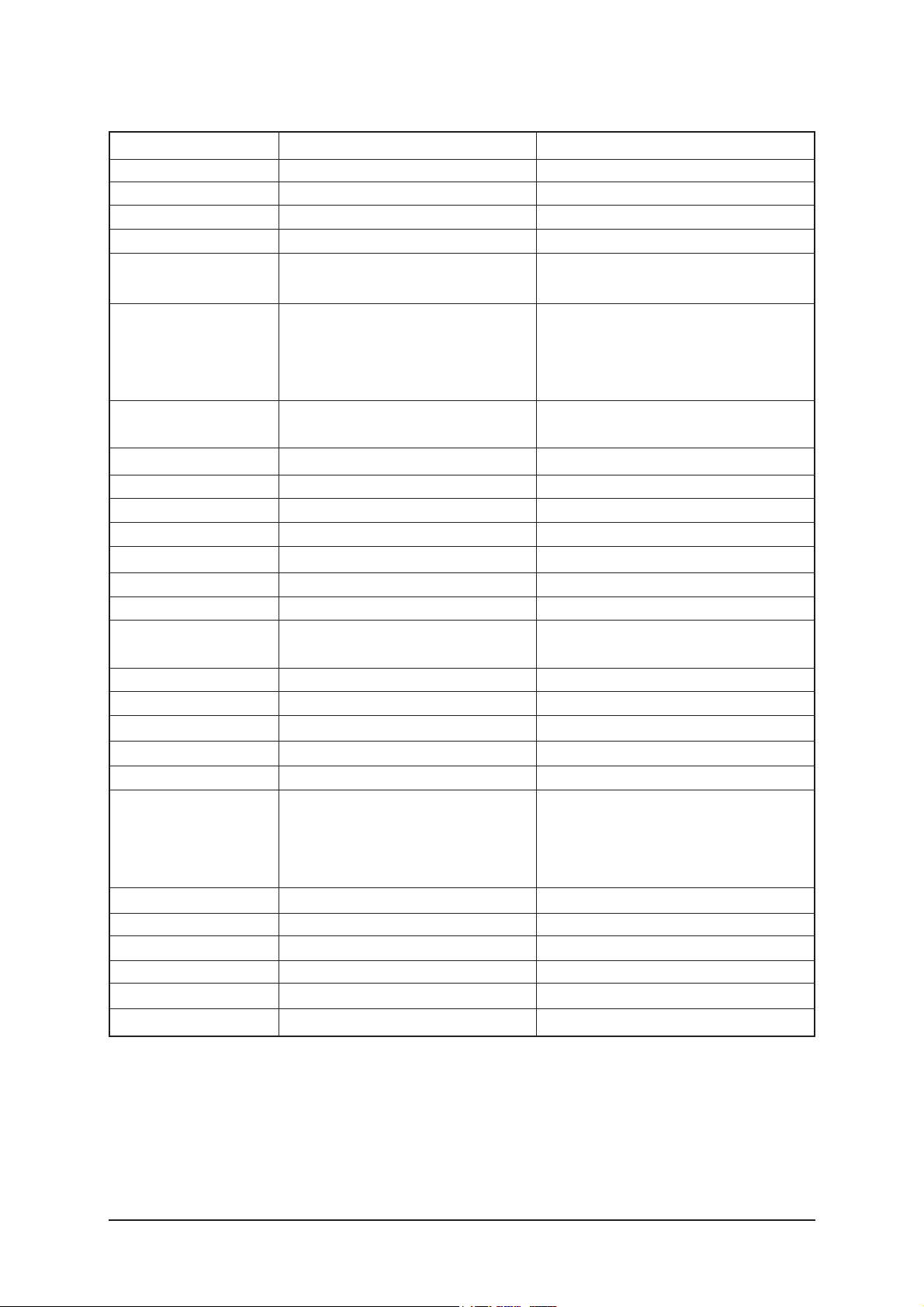
Item
Description
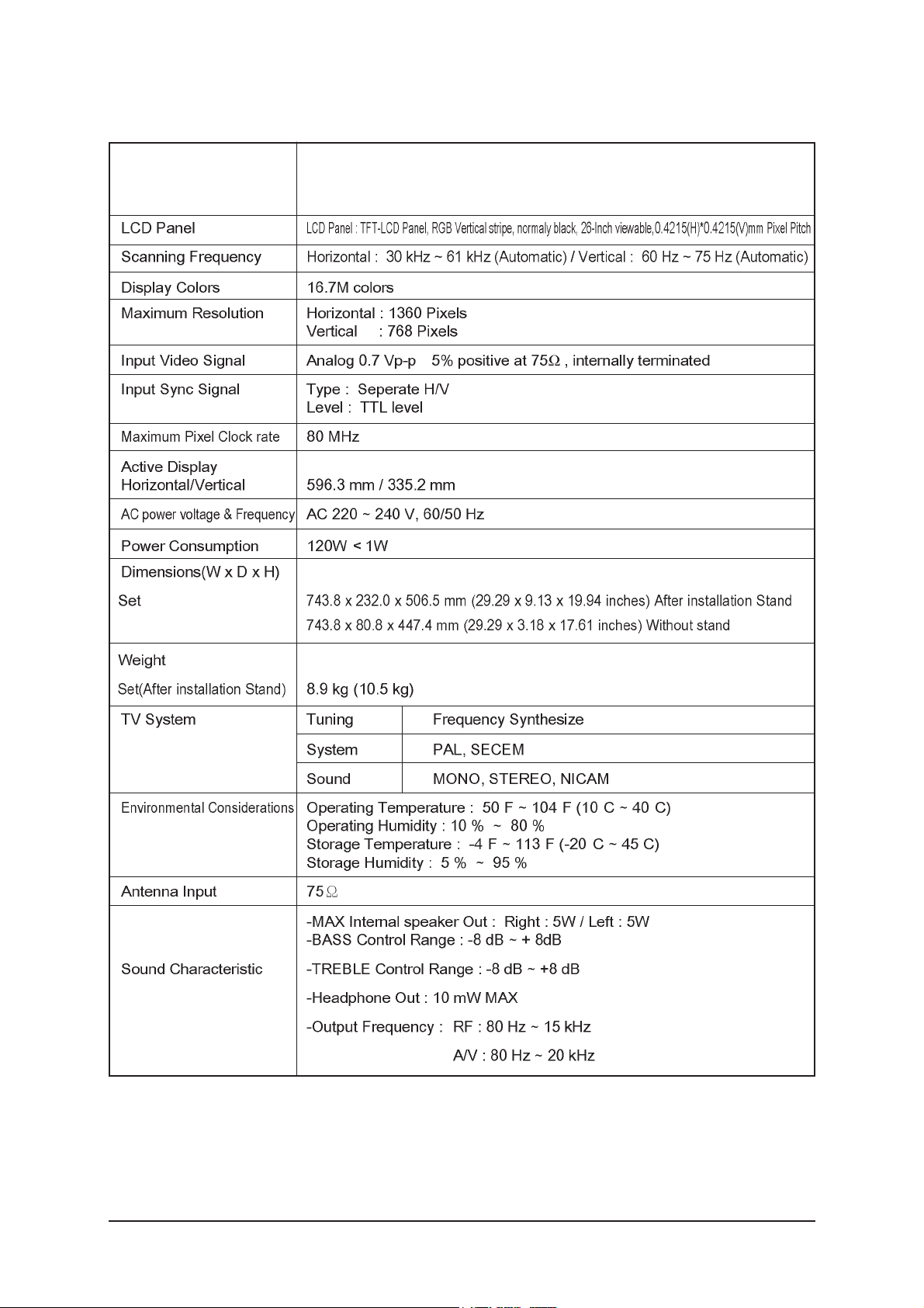
2-2 LE26S81BH Specifications
2 Product Specifications
2-3
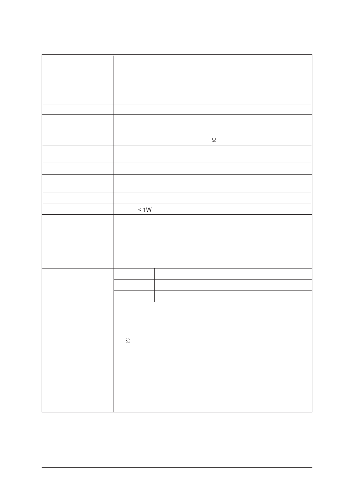
Item
Description
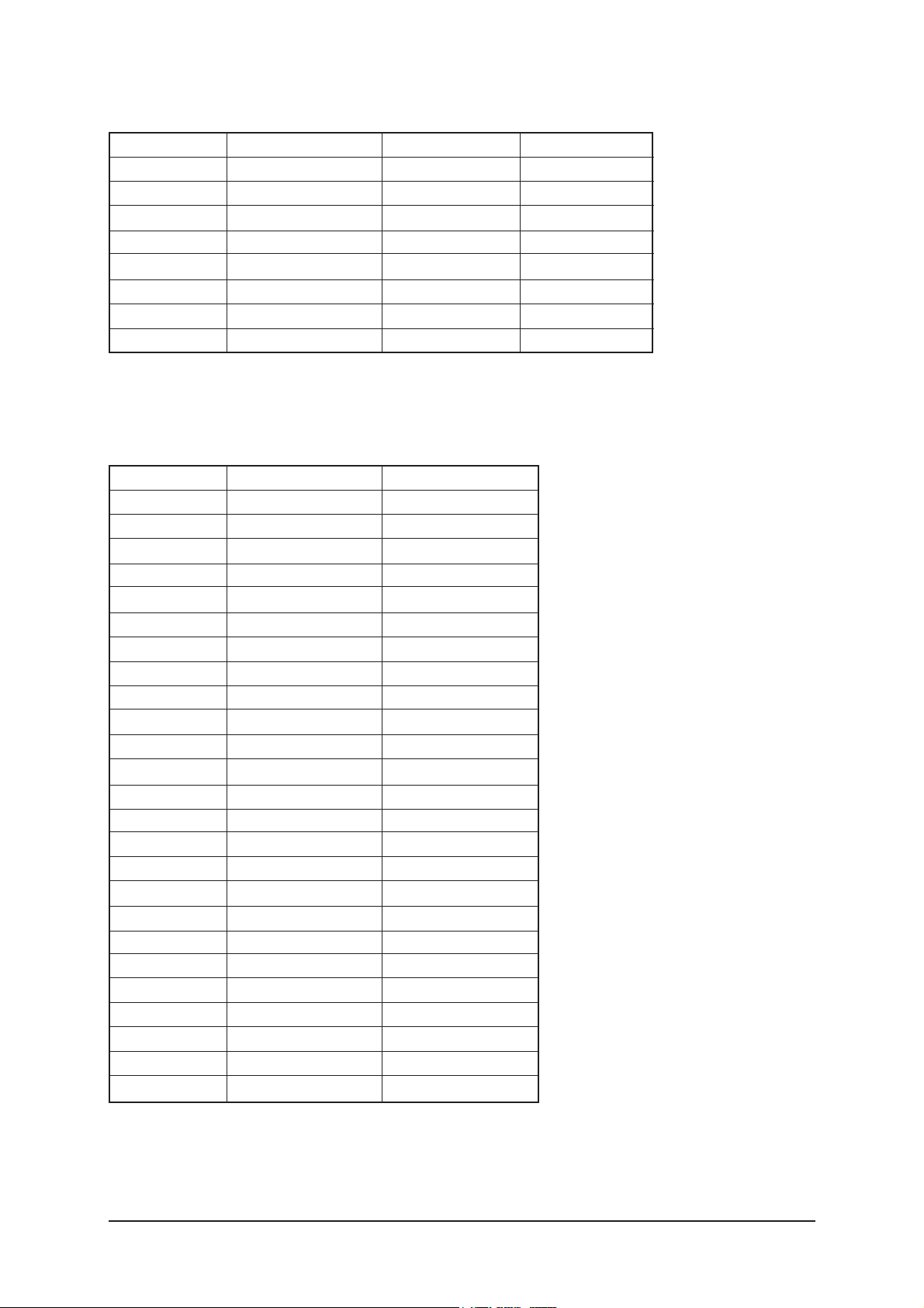
2-3
LE32S81BH Specifications
LCD Panel
TFT-LCD panel, RGB vertical stripe, normaly Black, 32-Inch viewable, 0.511 (H) x 0.511 (V) mm pixel pitchh
Scanning Frequency Horizontal : 30 kHz ~ 61 kHz (Automatic) / Vertical : 60 Hz ~ 75 Hz (Automatic)
Display Colors 16,777,216 colors
Maximum Resolution Horizontal : 1360 Pixels
Vertical : 768 Pixels
Input Video Signal Analog 0.7 Vp-p ± 5% positive at 75
, internally terminated
Input Sync Signal Type : Seperate H/V
Level : TTL level
Maximum Pixel Clock rate
80 MHz
Active Display
Horizontal/Vertical 697.68 mm / 392.26 mm
AC power voltage & Frequency AC 220 ~ 240V, 50 ~ 60 Hz
Power Consumption 150 W
Dimensions(W x D x H)
Set
874.3 x 291.3 x 577.2 mm (34.42 x 11.47 x 22.72 inches)After installation Stand
874.3 x 80.8 x 530.7 mm (34.42 x 3.18 x 20.90 inches) Without stand
Weight
Set
(After installation Stand) 11.7 kg (14.0 kg)
TV System Tuning Frequency Synthesize
System PAL, SECEM
Sound MONO, STEREO, NICAM
Environmental Operating Temperature : 50°F ~ 104°F (10°C ~ 40°C)
Considerations Operating Humidity : 10 % ~ 80 %
Storage Temperature : -4°F ~ 113°F (-20°C ~ 45°C)
Storage Humidity : 5 % ~ 95 %
Antenna Input 75
-MAX Internal speaker Out : Right : 5W / Left : 5W
-BASS Control Range : -8 dB ~ + 8dB
Sound Characteristic -TREBLE Control Range : -8 dB ~ +8 dB
-Headphone Out : 10 mW MAX
-Output Frequency : RF : 80 Hz ~ 15 kHz
A/V : 80 Hz ~ 20 kHz
2 Product Specifications
2-4
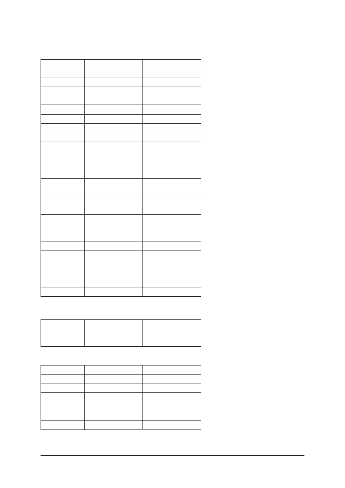
LCD Panel
TFT-LCD panel, RGB vertical stripe, normaly Black, 37-Inch viewable, 0.6 (H) x 0.6 (V) mm pixel pitchh
Scanning Frequency Horizontal : 30 kHz ~ 61 kHz (Automatic) / Vertical : 60 Hz ~ 75 Hz (Automatic)
Display Colors 16,777,216 colours
Maximum Resolution Horizontal : 1360 Pixels
Vertical : 768 Pixels
Input Video Signal Analog 0.7 Vp-p ± 5% positive at 75
, internally terminated
Input Sync Signal Type : Seperate H/V
Level : TTL level
Maximum Pixel Clock rate
80 MHz
Active Display
Horizontal/Vertical 819.6(H) / 460.8(V)
AC power voltage & Frequency AC 220 ~ 240V, 50 ~ 60 Hz
Power Consumption 170 W
Dimensions(W x D x H)
Set
1012.8 x 300.0 x 651.7 mm (39.90 x 11.81 x 25.65 inches)After installation Stand
1012.8 x 92.9 x 602.3 mm (39.90 x 3.65 x 23.71 inches) Without stand
Weight
Set
(After installation Stand) 17.2 kg (20.5 kg)
TV System Tuning Frequency Synthesize
System PAL, SECEM
Sound MONO, STEREO, NICAM
Environmental Operating Temperature : 50°F ~ 104°F (10°C ~ 40°C)
Considerations Operating Humidity : 10 % ~ 80 %
Storage Temperature : -4°F ~ 113°F (-20°C ~ 45°C)
Storage Humidity : 5 % ~ 95 %
Antenna Input 75
-MAX Internal speaker Out : Right : 10W / Left : 10W
-BASS Control Range : -8 dB ~ + 8dB
Sound Characteristic -TREBLE Control Range : -8 dB ~ +8 dB
-Headphone Out : 10 mW MAX
-Output Frequency : RF : 80 Hz ~ 15 kHz
A/V : 80 Hz ~ 20 kHz
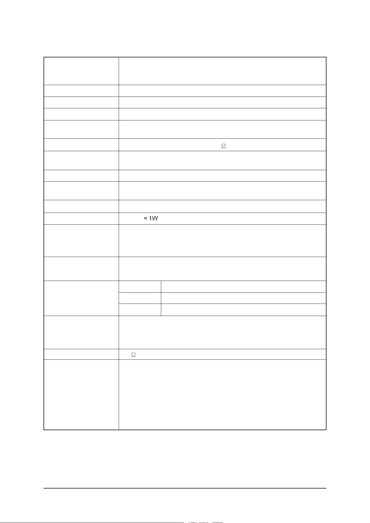
Item
Description
2-4 LE37S81BH Specifications
2 Product Specifications
2-5
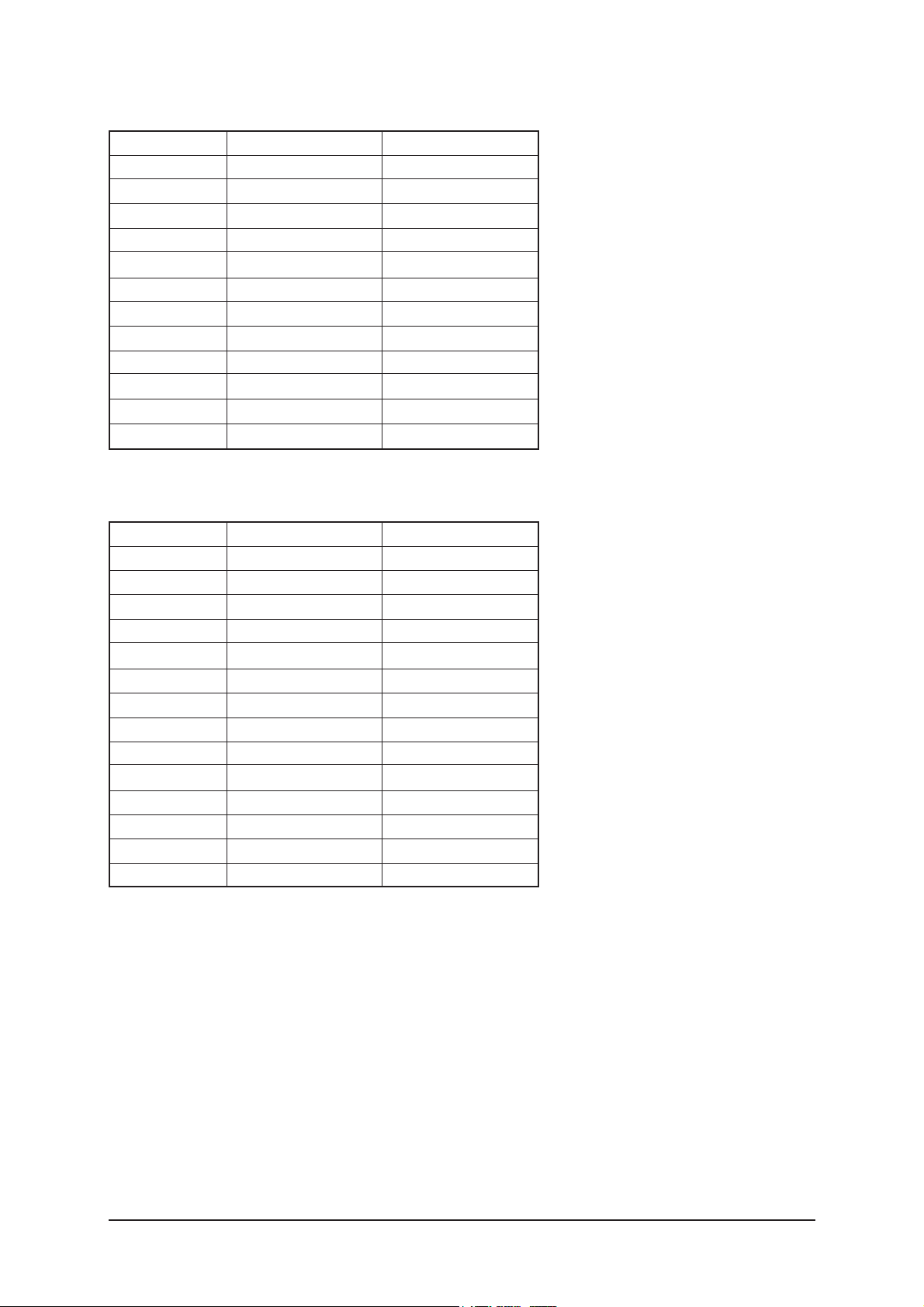
LCD Panel
TFT-LCD panel, RGB vertical stripe, normaly Black, 40-Inch viewable, 0.648(H) x 0.648(V) mm pixel pitch
Scanning Frequency Horizontal : 30 kHz ~ 61 kHz (Automatic) / Vertical : 60 Hz ~ 75 Hz (Automatic)
Display Colors 16,777,216 colors
Maximum Resolution Horizontal : 1360 Pixels
Vertical : 768 Pixels
Input Video Signal Analog 0.7 Vp-p ± 5% positive at 75
, internally terminated
Input Sync Signal Type : Seperate H/V
Level : TTL level
Maximum Pixel Clock rate
80 MHz
Active Display
Horizontal/Vertical 885.17 mm / 497.66 mm
AC power voltage & Frequency AC 220 ~ 240V, 50 ~ 60 Hz
Power Consumption 190 W
Dimensions(W x D x H)
Set
1083.8 x 300.0 x 690.0 mm (42.66 x 11.81 x 27.16 inches) After installation Stand
1083.8 x 94.9 x 638.5 mm (42.66 x 3.73 x 25.13 inches) Without stand
Weight
Set
(After installation Stand) 18.2 kg (21.5 kg)
TV System Tuning Frequency Synthesize
System PAL, SECEM
Sound MONO, STEREO, NICAM
Environmental Considerations Operating Temperature : 50°F ~ 104°F (10°C ~ 40°C)
Operating Humidity : 10 % ~ 80 %
Storage Temperature : -4°F ~ 113°F (-20°C ~ 45°C)
Storage Humidity : 5 % ~ 95 %
Antenna Input 75
-MAX Internal speaker Out : Right : 10W / Left : 10W
-BASS Control Range : -8 dB ~ + 8dB
Sound Characteristic -TREBLE Control Range : -8 dB ~ +8 dB
-Headphone Out : 10 mW MAX
-Output Frequency : RF : 80 Hz ~ 15 kHz
A/V : 80 Hz ~ 20 kHz
Item
Description
2-5
LE40S81BH Specifications
2 Product Specifications
2-6
LCD Panel
TFT-LCD panel, RGB vertical stripe, normaly Black, 47-Inch viewable, 0.7455(H) x 0.7455(V) mm pixel pitch
Scanning Frequency Horizontal : 30 kHz ~ 61 kHz (Automatic) / Vertical : 60 Hz ~ 75 Hz (Automatic)
Display Colors 16,777,216 colors
Maximum Resolution Horizontal : 1360 Pixels
Vertical : 768 Pixels
Input Video Signal Analog 0.7 Vp-p ± 5% positive at 75
, internally terminated
Input Sync Signal Type : Seperate H/V
Level : TTL level
Maximum Pixel Clock rate
80 MHz
Active Display
Horizontal/Vertical 1017.353 mm / 572.544 mm
AC power voltage & Frequency AC 220 ~ 240V, 50 ~ 60 Hz
Power Consumption 260 W
Dimensions(W x D x H)
Set
1220.2 x 326.0 x 776.0 mm (48.03 x 12.83 x 30.55 inches) After installation Stand
1220.2 x 110.9 x 709.0 mm (48.03 x 4.36 x 27.91 inches) Without stand
Weight
Set
(After installation Stand) 24.4 kg (29.8 kg)
TV System Tuning Frequency Synthesize
System PAL, SECEM
Sound MONO, STEREO, NICAM
Environmental Considerations Operating Temperature : 50°F ~ 104°F (10°C ~ 40°C)
Operating Humidity : 10 % ~ 80 %
Storage Temperature : -4°F ~ 113°F (-20°C ~ 45°C)
Storage Humidity : 5 % ~ 95 %
Antenna Input 75
-MAX Internal speaker Out : Right : 10W / Left : 10W
-BASS Control Range : -8 dB ~ + 8dB
Sound Characteristic -TREBLE Control Range : -8 dB ~ +8 dB
-Headphone Out : 10 mW MAX
-Output Frequency : RF : 80 Hz ~ 15 kHz
A/V : 80 Hz ~ 20 kHz
Item
Description
2-6
LE46S81BH Specifications
2 Product Specifications
2-7
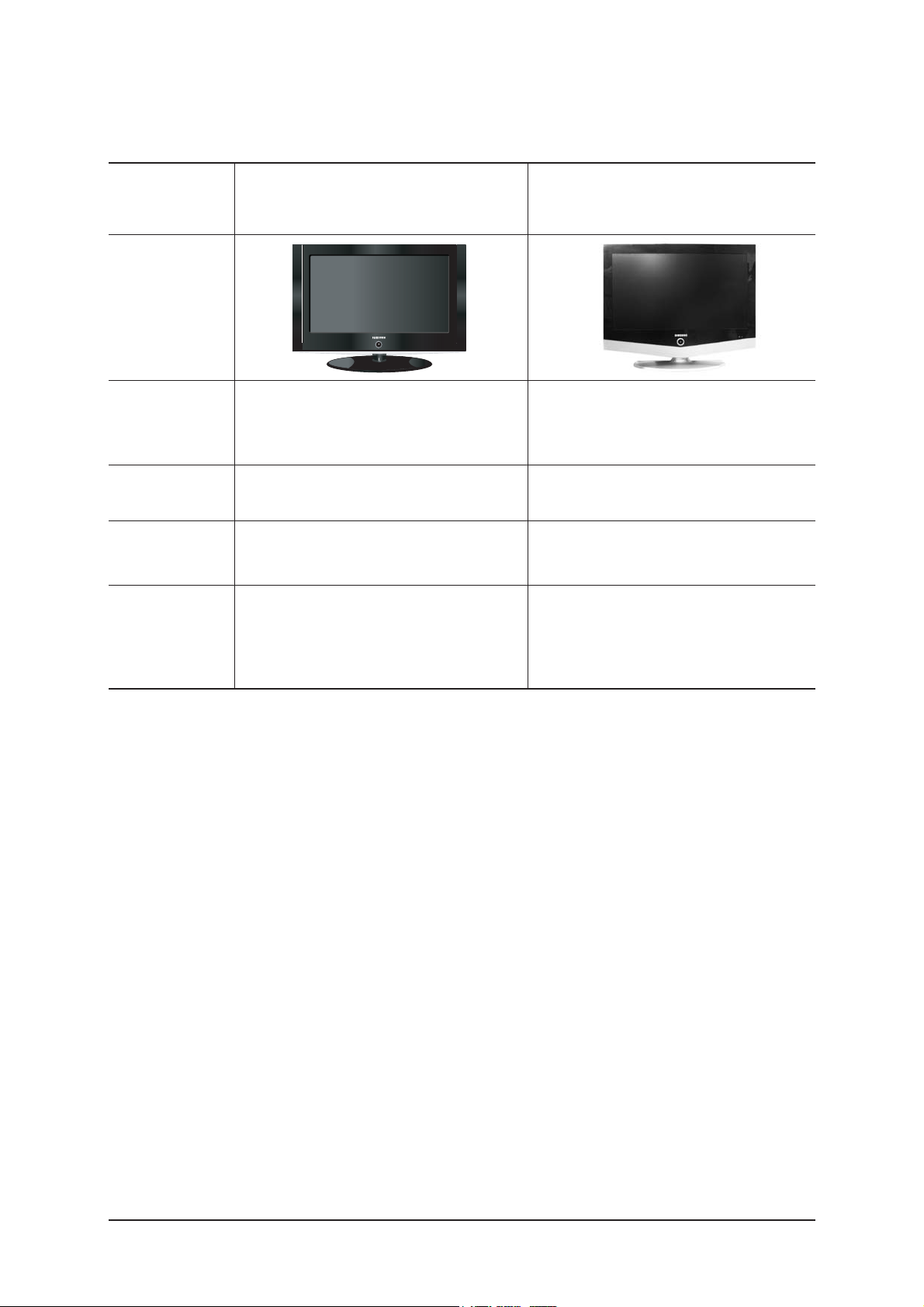
2-7 Spec Comparison
LE26R51B / LE32R51B / LE40R51B
Model
Design
Frequency
Horizontal
Vertical
Display Color
30 ~ 61 kHz
60 ~ 75 Hz
16,777,216 colors
30 ~ 61 kHz
60 ~ 75 Hz
16,777,216 colors
PC Resolution
Maximum mode
Input Signal
Sync Signal
Video Signal
Power
Consumption
Normal
Power Saving
140W / 184W / 285W
< 1W
120W / 150W / 170W / 190W / 260W
< 1W
H/V Separate, TTL, P. or N.
0.7 Vp-p @ 75ohm
H/V Separate, TTL, P. or N.
0.7 Vp-p @ 75ohm
WXGA, 1360 x 768 @ 60 HzWXGA, 1360 x 768 @ 60 Hz
LE26S81BH / LE32S81BH /
LE37S81BH / LE40S81BH / LE46S81BH
2 Product Specifications
2-8
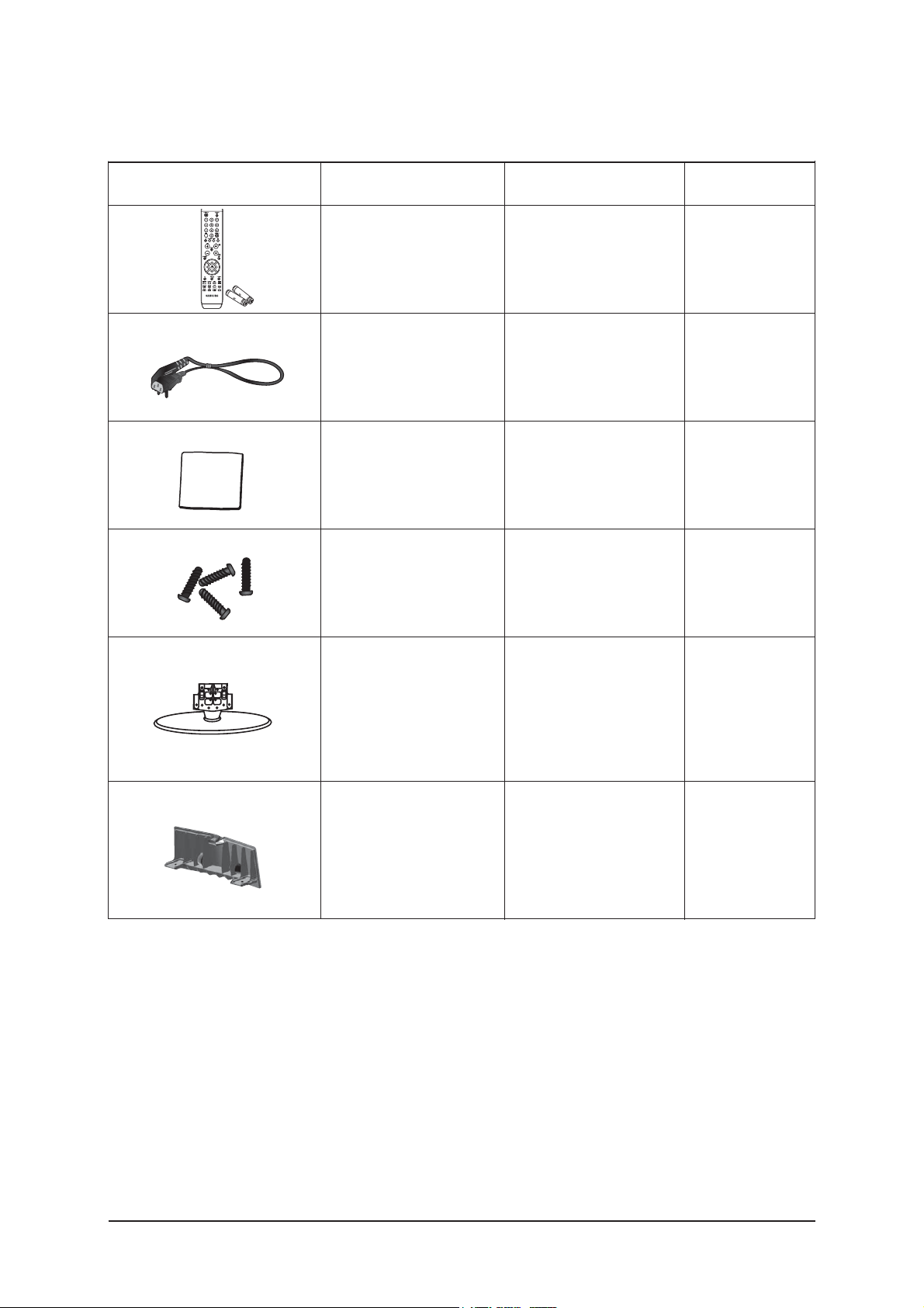
2-7 Option Specification
Item Item Name
Remote Control
&
Batteries (AAA x 2)
Power Cord
Cleaning Cloth
Stand
Cover-Bottom
BN59-00609A
3903-000145
BN63-001798A
26" : BN90-01212A
32" : BN90-01175A
37" : BN90-01214A
40" : BN90-01213A
46" : BN90-01215A
Stand Screw x 4
26" : 6002-001294
32" : 6002-001294
37" : 6002-001294
26" : BN63-03176B
32" : BN63-03093B
37" : BN63-03127B
40" : BN63-03127B
46" : BN63-03185B
Code.No Remark

3 Alignments and Adjustments
3-1
3 Alignments and Adjustments
3-1 Ser vice Instr uction
1. Usually, a color TV-VCR needs only slight touch-up adjustment upon installation.
Check the basic characteristics such as height, horizontal and vertical sync.
2. Use the specified test equipment or its equivalent.
3. Correct impedance matching is essential.
4. Avoid overload. Excessive signal from a sweep generator might overload the front-end
of the TV. When inserting signal markers, do not allow the marker generator to distort
test result.
5. Connect the TV only to an AC power source with voltage and frequency as specified on
the backcover nameplate.
6. Do not attempt to connect or disconnect any wire while the TV is turned on. Make sure
that the power cord is disconnected before replacing any parts.
7. To protect aganist shock hazard, use an isolation transform.
3 Alignments and Adjustments
3-2
3-2 How to Access Service Mode
3-2-1 Entering Factory Mode
" "
- If you have Factory remote - control
- The buttons are active in the service mode.
1. Remote - Control Key : Power, Arrow Up, Arrow Down, Arrow Left
Arrow Right, Menu, Enter, Number Key(0~9)
2. Function - Control Key : Power, CH +, CH -, VOL +, VOL -, Menu, TV/VIDEO(Enter)
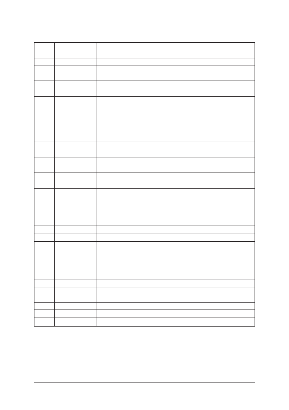
3-2-2 Panel Check
Specially for LE32S8**, You have to check Panel Maker Because of different adjustments as follows.
First of all, Check the label rating!
1) Label Rating File
If Panel Mark is "A", Set the factory mode
indicating as follows.
Panel BOM(Bill of material) : BN07-00421A
Connector between Panel and Power Unit
: BN39-00603L (250mm)
* Option Byte
1. Gamma "AUO"
2. Panel Option "AUO"
If Panel Mark is "S" or not printed.
Set the factory mode indicating as follows.
Panel BOM(Bill of material) : BN07-00453A
Connector between Panel and Power Unit
: BN39-00603G (300mm)
* Option Byte
1. Gamma "AMLCD"
2. Panel Option "AMLCD_INT"
If Panel Mark is "C" , Set the Factory mode
indicating as follows.
Panel BOM(Bill of Material) : BN07-00348A
Connecotor between Panel and Powe Unit :
BN39-00603L (250mm)
* Option Byte
1. Gamma " CMO "
2. Panel Option " CMO "
Others are same shown below.
PANEL MAKER
Power OFF
PICTURE ON
INFO
DISPLAY
MENU
MUTE
FACTORY
Power ON

3 Alignments and Adjustments
3-3
3-3 Factory Data
1. Calibration
2. Option Byte XXXX XXXX
3. W/B
4. W/B Movie
5. MTK8202
6. FBE2 option
7. Sound
8. YC Delay
9. Adjust
10. Bus Stop
11. Password 70 80 75 88
12. Checksum XXXX
13. Dynamic Contrast
14. Spread Spectrum
15. Reset
HDCP Write Success..(or Failure..)
T_JSMMPEU-1017 (Main Micom Ver) Month/ Day / Year / Hour/ Min./Sec.
Panel On Time(Hour) XXXXX
1. Calibration
1) AV Calibration
2) DTV Calibration
3) PC Calibration
4) HDMI Calibration
3 Alignments and Adjustments
3-4
NO
1
2
3
4
5
6
7
8
9
10
11
12
13
14
15
16
17
18
19
20
21
22
23
24
item
Panel Inch
Panel Vender
Panel Type
Gamma
Auto Power
Hotel Mode
Shop Mode
High Devi
Carrier Mute
TTX
TTX List
TTX Group
TTX ATM
Side Jack
Volume Table
Sound Wattage
HP Position
Language
HP Detect
PC Ident
WM Calib
Uart Select
Sub MCU PW Down
Sub MCU Use
Vendor
Code
SPEC
23"/26"/27"/32"/37"/40"/46"
AMLCD_INT,AMLCD_EXT,AUO_EXT_P,AUO_
EXT_N,AUO_INT,CMO_EXT,CMO_INT
32CMO,40AUO,37CPT,46AMLCD,26CMOTN,26AUO,
23AUOTN,32AMLCD,40AMLCD,32CPT,32AUO,37AUO,
32CMO,40AUO,37CPT,46AMLCD,26CMOTN,26AUO,
23AUOTN,32AMLCD,40AMLCD,32CPT,32AUO,37AUO,
off, 0.85, 0.90, 0.92, 0.94, 0.98, 1.07, 1.10, S1,
S2, S3, S4, S5, S6, S7
Off<->On
Off<->On
Off<->On
Off<->On
Off<->On
Off<->On
Flof, List
UserOSD, WestEurope, EastEurope, Russian
,Greek, Turkey, Arab/Hbrw, Farsian Arablic
off<->on
off<->on
Small, Large
LCD 10W, PDP 10W, PDP 15W
Side Rear
English, Germany, French, Italian, Swedish, Spain,
Netherlands, Portuguese, Greek, Czech, Serbian, Croatian,
Romanian, Hungarian, Polish, Russian, Bulgarian, Turkish,
Norwgian, Danish, Finnish
Active High, Active Low
Off<->On
Off<->On
Normal<->Debug/DL
Off<->On
Off<->On
26
BN07-00364A
V315B1-L01(5V,TN,72%)
26"
CMO_INT
26CMOTN
off
On
Off
Off
Off
Off
On
Flof
UserOSD
Off
On
Small
LCD 10W
Side
English
Active High
On
Off
Debug/DL
Off
Off
2. Option Byte
3 Alignments and Adjustments
3-5
item
Panel Inch
Panel Vender
Panel Type
Gamma
Auto Power
Hotel Mode
Shop Mode
High Devi
Carrier Mute
TTX
TTX List
TTX Group
TTX ATM
Side Jack
Volume Table
Sound Wattage
HP Position
Language
HP Detect
PC Ident
WM Calib
Uart Select
Sub MCU PW Down
Sub MCU Use
32
CMO
BN07-00348A
V315B1-L01(5V,SMVA72%)
32"
CMO_INT
32CMO
off
On
Off
Off
Off
Off
On
Flof
UserOSD
Off
On
Small
LCD 10W
Side
English
Active High
On
Off
Debug/DL
Off
Off
32
AUO V9
BN07-00421A
T315XW02(V9), 8bit, 5V
32"
AUO_INT
32AUO
off
On
Off
Off
Off
Off
On
Flof
UserOSD
Off
On
Small
LCD 10W
Side
English
Active High
On
Off
Debug/DL
Off
Off
32
AMLCD VE
BN07-00453A
5V,SMVA 72%,
32"
AMLCD_INT
32AMLCDV
0.9
On
Off
Off
Off
Off
On
Flof
UserOSD
Off
On
Small
LCD 10W
Side
English
Active High
On
Off
Debug/DL
Off
Off

3 Alignments and Adjustments
3-6
37
CPT
BN07-00366A
CLAA370WA03(5V,MVA,72%)
37"
CPT_INT
37 CPT
off
On
Off
Off
Off
Off
On
Flof
UserOSD
Off
On
Small
LCD 10W
Side
English
Active High
On
Off
Debug/DL
Off
Off
37
AUO
BN07-00393A
T370XW02(12V,AMVA 72%)
37"
AUO_EXT_P
37 AUO
off
On
Off
Off
Off
Off
On
Flof
UserOSD
Off
On
Small
LCD 10W
Side
English
Active High
On
Off
Debug/DL
Off
Off
item
Panel Inch
Panel Vender
Panel Type
Gamma
Auto Power
Hotel Mode
Shop Mode
High Devi
Carrier Mute
TTX
TTX List
TTX Group
TTX ATM
Side Jack
Volume Table
Sound Wattage
HP Position
Language
HP Detect
PC Ident
WM Calib
Uart Select
Sub MCU PW Down
Sub MCU Use
3 Alignments and Adjustments
3-7
40
AUO
BN07-00370A
T400XW02(5V,AMVA,72%)
40"
AUO_INT
40AUO
off
On
Off
Off
Off
Off
On
Flof
UserOSD
Off
On
Small
LCD 10W
Side
English
Active High
On
Off
Debug/DL
Off
Off
40
AMLCD
BN07-00387A
LTA400WT-L06(12V,SPVA 72%)
40"
AMLCD INT
40 AMLCD
off
On
Off
Off
Off
Off
On
Flof
UserOSD
Off
On
Small
LCD 10W
Side
English
Active High
On
Off
Debug/DL
Off
Off
40
AMLCD VE
BN07-00451A
12V,SMVA 72%,
40"
AMLCD INT
40 AMLCDV
0.9
On
Off
Off
Off
Off
On
Flof
UserOSD
Off
On
Small
LCD 10W
Side
English
Active High
On
Off
Debug/DL
Off
Off
40
AUO VE
BN07-00448A
5V,SMVA 72%,
40"
AUO_INT
40 AUO
0.92
On
Off
Off
Off
Off
On
Flof
UserOSD
Off
On
Small
LCD 10W
Side
English
Active High
On
Off
Debug/DL
Off
Off
3 Alignments and Adjustments
3-8
46
AMLCD
BN07-00389A
LTA460WT-L11(12V,SPVA72%)
46"
AMLCD_INT
46AMLCD
off
On
Off
Off
Off
Off
On
Flof
UserOSD
Off
On
Small
LCD 10W
Side
English
Active High
On
Off
Debug/DL
Off
Off
46
AMLCD VE
BN07-00452A
LTA460WT-L12(12V,SMVA,72%)
46"
AMLCD_INT
46AMLCDV
0.9
On
Off
Off
Off
Off
On
Flof
UserOSD
Off
On
Small
LCD 10W
Side
English
Active High
On
Off
Debug/DL
Off
Off
item
Panel Inch
Panel Vender
Panel Type
Gamma
Auto Power
Hotel Mode
Shop Mode
High Devi
Carrier Mute
TTX
TTX List
TTX Group
TTX ATM
Side Jack
Volume Table
Sound Wattage
HP Position
Language
HP Detect
PC Ident
WM Calib
Uart Select
Sub MCU PW Down
Sub MCU Use
3 Alignments and Adjustments
3-9
3. White Balance
No
1
2
3
4
5
6
7
8
item
SubBright
Roffset
Goffset
Boffset
SubContrast
RGain
GGain
BGain
RF/AV
128
128
128
130
145
120
128
146
HDMI
4. W/B Movie
NO
1
2
3
4
5
6
7
8
9
10
11
12
13
14
15
16
17
18
19
20
21
22
23
24
25
item
W/B MOVIEOn/Off
Service P Mode
Service Color Tone
MSub Brightness
MSub Contrast
Warm1 Red Gain
Warm1 Blue Gain
Warm1 Red Offset
Warm1 Blue Offset
Warm2 Red Gain
Warm2 Blue Gain
Warm2 Red Offset
Warm2 Blue Offset
Normal Red Gain
Normal Blue Gain
Normal Red Offset
Normal Blue Offset
Cool2 Red Gain
Cool2 Blue Gain
Cool2 Red Offset
Cool2 Blue Offset
Mov. Contrast
Mov. Brightness
Mov. Color
Mov. Sharpness
RF/AV/S_video
Off
Movie
Warm2
128
128
166
54
128
126
171
36
127
129
137
91
129
127
114
146
128
127
80
45
55
45
3 Alignments and Adjustments
3-10
5. MTK8202
1) Cal. Adjustment
2) Cal. Target
NO
1
2
3
4
5
6
7
8
9
10
11
12
13
14
15
16
17
18
19
20
21
22
23
24
25
item
R_Offset
G_Offset
B_Offset
R_Gain
G_Gain
B_Gain
Y_Offset
Cb_Offset
Cr_Offset
Y_Gain
Cb_Gain
Cr_Gain
CVBS Offset
CVBS Gain
CVBS U
CVBS V
HDMI R_Gain Ref.
HDMI G_Gain Ref.
HDMI B_Gain Ref.
HDMI R_Offset Ref.
HDMI G_Offset Ref.
HDMI B_Offset Ref.
2nd Cal Error AV
2nd Cal Error DTV
LVDS Control
value
30
32
23
77
85
89
21
39
41
41
41
41
55
52
0
0
229
229
229
16
16
16
2
2
55
NO
1
2
item
Black Target
White Target
value
1
235
3) Scart RGB
NO
1
2
3
4
5
6
item
SC1_R_Offset
SC1_G_Offset
SC1_B_Offset
SC1_R_Gain
SC1_G_Gain
SC1_B_Gain
ALL Mode
115
115
115
70
70
70
3 Alignments and Adjustments
3-11
4) Picture enhance 1
NO
1
2
3
4
5
6
7
8
9
10
11
12
item
Dynamic Contrast
Dynamic CE
Dynamic Dimming
Black_Min
Black_Middle
Black_Max
Cut Off
Upper
Center L Lmt
Center R Lmt
Ugain Max
Lgain Max
value
on
on
on
14
26
36
4
28
6
26
16
8
5) Picture enhance 2
NO
1
2
3
4
5
6
7
8
9
10
11
12
13
14
item
PreLGain_Main
PreMGain_Main
PreHGain_Main
PreLGain_Sub
PreMGain_Sub
PreHGain_Sub
LocalLGain
LocalMGain
LocalHGain
PostLGain
PostMGain
PostHGain
Vgain
Sub Color
value
64
64
64
64
64
64
72
80
64
72
72
84
0
28
3 Alignments and Adjustments
3-12
6) FBE2 option
NO
1
2
3
4
5
6
7
8
9
10
11
12
13
14
15
16
17
18
19
20
21
22
23
item
Patt-Sel
B-Slope gain
B-Tilt min
B-Tilt max
B-Tilt slpe
Lfunc-Basis
Hfunc-Basis
Mean-Offset1
Mean-Offset2
Mean-Slope
Input-Offset
Input-gain
ACR-Offset
ACR-Th1
ACR-Th2
Skin-Enable
Skin-Tu
Skin-Tv
M-Skin-Tu
M-Skin-Tv
Sub color
M-Au-Sub color
M-Wi-Sub color
value
0
64
20
120
128
75
88
75
150
41
128
128
30
30
100
On
22
22
128
128
143
128
128
3 Alignments and Adjustments
3-13
7) Sound
NO
1
2
3
4
5
6
7
8
9
10
11
12
13
14
15
16
17
18
19
20
21
22
23
24
25
item
AM_mute Th_High
AM_mute Th_Low
FM Mute
FM_mute Th_High
FM_mute Th_Low
Correct Threshold
Sync Loop
Error Threshold
Parity Error Thrd
Every Num Frames
Num of Check
Num of Double Chk
Mono Weight
Stereo Weight
Dual Weight
M2S Threshold
S2M Threshold
NICAM FINE VOL
FM FINE VOL
AM FINE VOL
FINE TUNE VOL
SC1 Fine Vol
SC2 Fine Vol
Output Matrix
Speaker EQ
value
9
8
Off
34
32
6
201
8
48
512
10
10
1
1
1
10
10
20
20
19
20
21
21
Bypass
Off
 Loading...