

Samsung LE23R32B, LE26R32B Service manual

SERVICE
Manual
LCD-TV
Features
LCD-TV
Chassis GRM23HEU
GRM26HEU
Model LE23R32B
LE26R32B
- HDMI/DVI, PC(Analog), 1 Component,
2 SCART, 1 Composite, S-Video, RF
- Brightness : 500cd/
- Contrast Ratio : 800:1
- Response time : 8ms

ii
Copyright
©2006 by Samsung Electronics Co., Ltd.
All rights reserved.
This manual may not, in whole or in part, be copied,
photocopied, reproduced, translated, or converted to
any electronic or machine readable form without prior
written permission of Samsung Electronics Co., Ltd.
LE23R32B / LE23R32B Service Manual
First edition March 2006.
Printed in Korea.
Trademarks
Samsung is the registered trademark of Samsung
Electronics Co., Ltd.
LE23R32B / LE23R32B and MacMaster Cable
Adapter are trademarks of Samsung Electronics Co.,
Ltd.
Macintosh, Power Macintosh are trademarks of Apple
Computer, Inc.
All other trademarks are the property of their respective
owners.
Contents

Contents

Samsung Electronics Co.,Ltd.
416, Maetan-3Dong, Yeongtong-Gu, Suwon City,
Gyeonggi-Do, Korea, 443-742
Printed in Korea
P/N : BN82-00168C-00
URL : http://itself.sec.samsung.co.kr/
-This Service Manual is a property of Samsung
Electronics Co., Ltd.
Any unauthorized use of Manual can be punished
under applicable International and/or domestic law.

3 Alignments and Adjustments
3-1
3 Alignments and Adjustments
3-1 General Alignment Instuction
1. Usually, a color LCD-TV needs only slight touch-up adjustment upon installation.
Check the basic characteristics such as height, horizontal and vertical sync.
2. Use the specified test equipment or its equivalent.
3. Correct impedance matching is essential.
4. Avoid overload. Excessive signal from a sweep generator might overload the front-end
of the TV. When inserting signal markers, do not allow the marker generator to distort test result.
5. Connect the TV only to an AC power source with voltage and frequency as specified on
the backcover nameplate.
6. Do not attempt to connect or disconnect any wire while the TV is turned on. Make sure
that the power cord is disconnected before replacing any parts.
7. To protect aganist shock hazard, use an isolation transformer.

3 Alignments and Adjustments
3-2
3-2 Factory Mode Adjustments
3-2-1 Entering Factory Mode
To enter 'Service Mode' Press the remote -control keys in this sequence :
- If you do not have Factory remote - control
3-2-2 Factory Mode Tree
- If you have Factory remote - control
[INFO] -> [FACTORY]
INFO MUTE Power OnMENU
1. Calibration
2. Option Byte
3. W/B
4. VCTi
5. YC Delay
6. FLI 5928
7. Adjust
8. Test Pattern
9. Password
10. Check Sum 0000
11. Spread spectrum
12. HDCP
13. DownLoad : Off
14. WatchDog Timer
15. Reset
T_BRD23PEU-1004
Month/ Day / Year / Hour/ Min./Sec.
P_TRNPEU-1002
Panel On Time(Hour) XXXXX
1. Calibration
AV Calibration
DTV Calibration
PC Calibration
3. White Balance
Sub Bright : 128
R off set : 128
G off set : 128
B off set : 128
Sub contrast : 128
R gain : 128
G gain : 128
B gain : 128
Low Light : 274/274 1.0 +/- 0.15
High Light : 274/274 55 ÀÌ»ó
2. Option Byte
Panel option :
23" AUO / 26" CMO
Dimming
: A_P3(AM7), P (CMO)
Gamma : On
Auto Power :
On
Video Mute : 8
Language : English
Hotel Mode : Off
V-Chip : Off
Auto FM : Off
High Dev. : Off
TTX List : Flof
MCC : Off
TTX Group : User OSD
Shop Mode : Off
------ : Off
4.
VCTi
VCTi Page 1
VCTi Page 2

3 Alignments and Adjustments
3-3
1. Calibration
2. Option Byte
3. W/B
4. VCTi
5. YC Delay
6. FLI 5928
7. Adjust
8. Test Pattern
9. Password
10. Check Sum 0000
11. Spread spectrum
12. HDCP
13. DownLoad : Off
14. WatchDog Timer
15. Reset
T_BRD23PEU-1004
Month/ Day / Year / Hour/ Min./Sec.
P_TRNPEU-1002
Panel On Time(Hour) XXXXX
5. YC Delay
RF PAL-B/G : 5
RF PAL-D/K : 6
RF PAL-I : 5
RF PAL-L/L' : 5
RF SECAM-B/G : 2
RF SECAM-D/K : 0
RF SECAM-I : 2
RF SECAM-L/L : 5
RF NTSC 3.58 : 5
RF NTSC 4.43 : 5
AV PAL : 5
AV SECAM : 2
AV NTSC 3.58 : 5
AV NTSC 4.43 : 5
AV PAL 60 : 5
6. FLI 5928
1.
Component Calibration--(ADC)
2. PC Calibration--(ADC)
3. ACC/ACM
4. TNR
5. Picture Enhance
6. Calibration Target
7. Adjust
User Control lnitial
LNA PLUS
Hotel Option
11. Spread Spectrum
Spread Spectrum : ON
Spread Spectrum Range : 3
Step : 12
LVDS_ICTRL : 0
Memc Clk Freq0 : 122
Memc Clk Freq1 : 180
Sdram Clk Delay : 81
Sdram Drive0 : 52
Sdram Drive1 : 51
8. Test Pattern ------------ 0
10. Check Sum : XXXX
12. HDCP : XXXX
13. DownLoad On/Off
14. WatchDog Timer Off
15. Reset
9. Password : 80 80 80 80

3 Alignments and Adjustments
3-4
3-3 White Balance - Calibr ation
3-3-2 White Balance - Adjustment
3-3-1 White Balance -Calibration
3-3-3 Conditions for Measurement
1. Calibration
AV Calibration
DTV Calibration
PC Calibration
(Calibration Condition refer to next page)
3. W/B
(low light) (high light)
1. On the basis of toshiba ABL pattern : High Light level (57 IRE)
- INPUT SIGNAL GENERATOR : MSPG-925LTH
* Mode NO 2: 768 x 575 @ 50Hz(PAL composite)
NO 6 : 1280 x 720 @ 60 Hz (Component 720P)
NO 21 : 1024 x 768 @ 60 Hz
*
Pattern
NO 24: chess pattern
NO 16 : Toshiba ABL Pattern
NO 17 : 16 gray
2. Optical measuring device : CA210 (FL)
Please use the MSPG-925 LTH generator for model LE23R71BX.
(W/B adjustment Condition refer next page)
Sub Bright Sub Contrast
R offset R gain
G offset G gain
B offset B gain

3 Alignments and Adjustments
3-5
2. Adjust the white balance of AV, Component and DVI Modes.
a) Set the input to the mode in which the adjustment will be made (AV Component DVI).
* Input signal - VIDEO Mode : Model #1 (744*484 Mode), Pattern #16
- Component, DVI Mode : Model #6 (1280*720 Mode), Pattern #16
b) Enter factory W/B.
c) Adjust the low light.
- Adjust sub - Brightness to set the 'Y' value.
- Adjust red offset ('x') and blue offset ('y') to the color coordinates. ( x : 263, y : 267, Y : 1.3 ft)
* Do not adjust green offset data.
3-3-4 Method of Adjustment
1. Adjust the basic level of A/V and Component and PC input signals.
a) Set the input to the mode in which the adjustment will be made(A/V -> Component -> PC).
* Input signal - A/V Mode : Mode#2(768 x 575@50Hz), Pattern #24 ( picture 3-1 )
- Component Mode : Model # 6 ( 1280*720 @ 60Hz ) , Pattern #15 ( picture 3-2 ).
- PC Mode : Model #21 ( 1024*768 @ 60Hz ) , Pattern #17 ( picture 3-3 ).
b) Enter Factory Calibration ( A/V , DTV , PC Mode Only).
* AV Calibration -> Source change for Component -> DTV Calibration -> Source change for PC -> PC
Calibration
Picture 3-3 16gray
Picture 3-2 Color barPicture 3-2 Color bar
Picture 3-1 Chess pattern

3 Alignments and Adjustments
3-6
Picture 3-4 Toshiba ABL Pattern
High light
Measurement point
d) Adjust the high light. (Refer to table 1, 2 in adjustment position by mode)
- Adjust red gain ('x') and blue gain ('y') to the color coordinates. ( x : 263, y : 267 )
* Do not adjust the green gain and sub-contrast (Y) data.
Picture 3-3 Toshiba ABL Pattern
Low light
Measurement point

3 Alignments and Adjustments
3-7
3-4 Bordeaux Micom Update
3-4-1 Installing G-Probe
1. Uncompress GProbe5.1.0.18.zip.
2. Run GProbe5.1.0.18.exe.
3. The files are created in the C:
Program Files Genesis Microchip GProbe 5 folder.
4. Copy the ispoak_spi.hex file to the C:
Program Files Genesis Microchip GProbe 5 folder.
5. Copy the bordeaux.txt, torino.txt file to the C:
Program Files Genesis Microchip GProbe 5 folder.
(bordeaux.txt or torino.txt have the command list to download. The file name should be changed.)
6. Execute the 'Gprobe 5'
7. Click the 'connection settings' button.
8. Change the connection from 'Serial' to 'Parallel'

3 Alignments and Adjustments
3-8
9. Set the 'Pin assignments'
3-4-2 Connecting the download JIG to the MAIN PCB
Connect the DDC manager from Parallel of PC to D-sub of set.

3 Alignments and Adjustments
3-9
3-4-3 Update Procedures
1. Execute the 'Gprobe 5'
2. Open the command list file(ex. bordeaux.txt or torino.txt. The file name should be changed.)
1) Click the Button to open the file>
2) Open the command list file.
3 Alignments and Adjustments
3-10
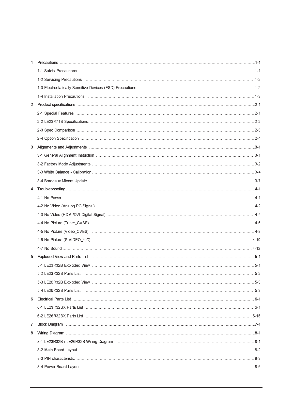
3) You can see the file contents. It's command lists. (In this case the command file is insam.txt for
example.)
4) Check the the SOFT name and path to download. (For example T-BRD23US-0152.hex is used at
insam folder in C driver)
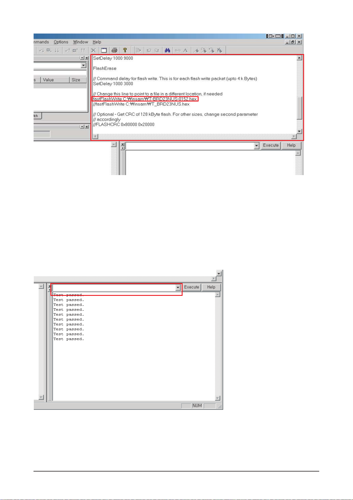
3. Enter to '13.download' mode in service menu.
4. Check the connection with 'test' command.
If you can get 'Test passed.' massage, the connection is OK or else check the Jig cable.
5. Execute the command list file. For it enter 'batch file name.txt'.
If you can get 'Batch: command Successful' massage Download is all done.
test

3 Alignments and Adjustments
3-11

3 Alignments and Adjustments
3-12
Memo

7 Block Diagrams
7-1
7 Block Diagram
- This Document can not be used without Samsung’s authorization

7 Block Diagrams
7-2
Memo

13 Circuit Descriptions
13-1
13 Circuit Descriptions
13-1 Block description
consists of three main blocks
1. Main board : Video signal processing
2. SMPS board : Power supply
3. Panel Inverter & T-con board : LCD Panel control

13 Circuit Descriptions
13-2
*
VCTi : IF AV1/2, S-Video input and video decoding, Audio signal processing.
*
FLI5928H : - Scaler IC.
- Component, PC, HDMI/DVI input and LVDS signal output.
*
BA7657 : component 1/2, Switching IC.
13-2 Main Block

13 Circuit Descriptions
13-3
13-3 SMPS Board
13-3-1 SMPS Diagram (Free_Volt)

Memo
13 Circuit Descriptions
13-4

11 Disassembly and Reassembly
11-1
11 Disassembly and Reassembly
This section of the service manual describes the disassembly and reassembly procedures for the TFT-LCD TV.
WARNING: This monitor contains electrostatically sensitive devices. Use caution when handling
these components.
11-1 LE23R32B Disassembly
Cautions: 1. Disconnect the monitor from the power source before disassembly.
2. Follow these directions carefully; never use metal instruments to pry apart the
cabinet.
Description Picture Description
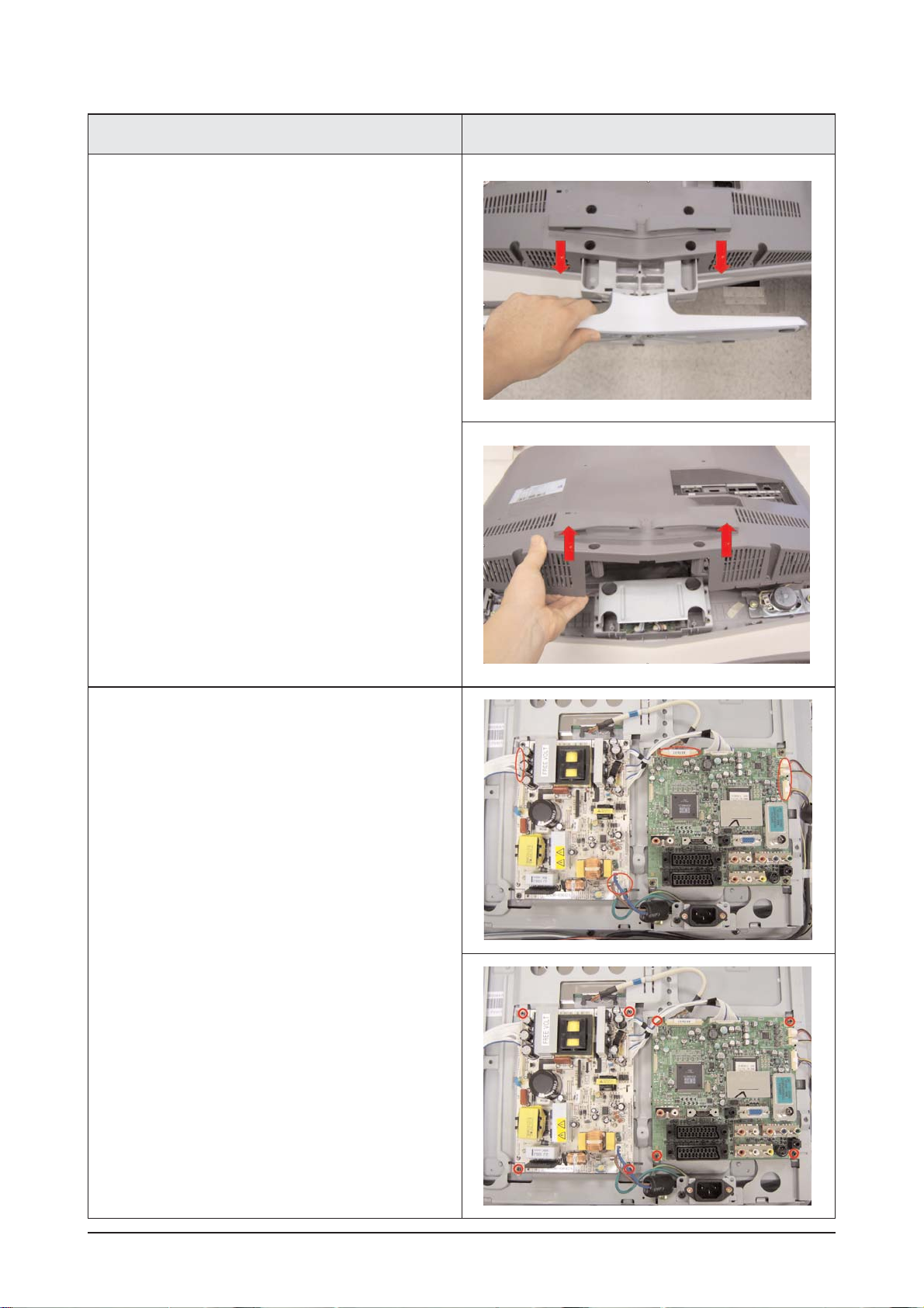
1. Place LCD TV face down on cushioned table.
Remove 13 screws from the rear cover.
Remove 2 screws from the jack cover
11 Disassembly and Reassembly
11-2
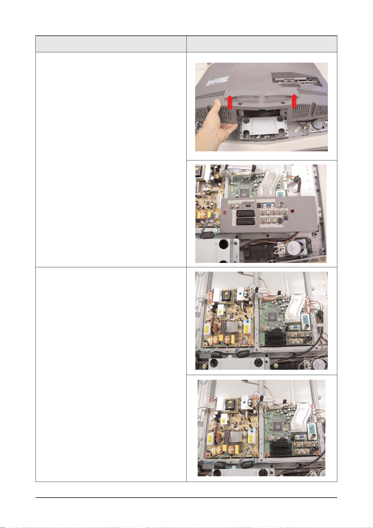
3. Disconnect cables and remove screws from the
boards.
Description Picture Description
2. Remove stand and lift up the rear cover.

11 Disassembly and Reassembly
11-3
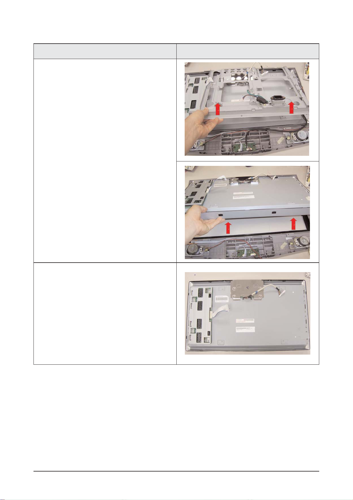
5. Lift up the stand brkt and remove 8 screws from
the panel brkt.
Description Picture Description
4. Lift up the boards and remove screws from the
stand brkt.
11 Disassembly and Reassembly
11-4
7. LCD panel
Description Picture Description
6. Lift up the brkt and LCD panel.

11 Disassembly and Reassembly
11-5
11-2 LE26R32B Disassembly
Cautions: 1. Disconnect the monitor from the power source before disassembly.
2. Follow these directions carefully; never use metal instruments to pry apart the
cabinet.
Description Picture Description
1. Place LCD TV face down on cushioned table.
and Remove the Stand 13 screws from the rear
cover.
11 Disassembly and Reassembly
11-6
3. Disconnect cables and remove screws from the
boards
Description Picture Description
2. lift up the rear cover.
Remove 2 screws and lift up the jack cover.

11 Disassembly and Reassembly
11-7
5. Remove 6 screws from the stand brkt and Lift
up the Stand brkt.
Description Picture Description
4. Lift up the main board.
Remove 2 screws.
 Loading...