

Page 1

Specifications
Alignment and Adjustments
Troubleshooting
Exploded View and Parts List
Service Item
Block Diagrams
Schematic Diagrams
1.
2.
3.
4.
5.
6.
7.
DLP TV
Chassis : L64A(N_L5)_Robocop-1
Model : HLR4677WX/XAA (HL-R4677W)
HLR5677WX/XAA (HL-R5677W)
SERVICE
Manual
DLP TV CONTENTS
Page 2

This Service Manual is a property of Samsung Electronics Co.,Ltd.
Any unauthorized use of Manual can be punished under applicable
International and/or domestic law.
© Samsung Electronics Co., Ltd. DEC. 2004
Printed in Korea
AA82-01909A
ELECTRONICS
Page 3

Specifications
Samsung Electronics
1-1
1. Specifications
Model HL-R4677W HL-R5677W
Voltage AC 120V
Frequency of Operation 60Hz
Power Consumption 230 Watts
Dimensions
(W x D x H)
1094x339x814 mm
43.07x13.35x32.05 inches
1330x396x962.5 mm
52.36x15.59x37.89 inches
Weight 71.65lbs/32.5Kg 93.7lbs/42.5Kg
Page 4

1-2
Samsung Electronics
MEMO
Page 5

Alignment and Adjustments
Samsung Electronics 2-1
Factory
DDP1011(L5)
DNIe
ADV7402(M)
ADV7402(S)
uPD64083
MSP4440
CCA
Cinema CCA
SP Actuator
CHECKSUM 0000
OPTION
SERVICE
T_RoboAUS0_XXXX
20XX_XX_XX
T-DTVUCOM5-XXXX
T-RoboAUS1_XXXX
2-1 When Entering Service Mode:
2-1-1 Service Mode Entry Method
1. Turn off the power to make the SETSTAND-BY mode.
2. In order to enter the Service Mode, Press "Mute" → "1” → "8" → "2" → "POWER" button on the Remote Control.
In case entry into SERVICE MODE is unsuccessful, repeat the procedures above.
2-1-2 Initial DISPLAY State in times of SERVICE MODE Switch overs
2-1-2(A) OSD DISPLAY
2-1-2(B) BUTTONS OPERATIONS WITHIN SERVICE MODE
2. Alignment and Adjustments
MENU Full Menu Display / Move to Parent Menu
Direction keys ▲ / ▼
Item Selection by Moving the Cursor
Direction keys ◀ / ▶
Data Increase/Decrease for the Selected Item
Source Cycles through the active input source that are connected to the unit
Page 6

Alignment and Adjustments
2-2 Samsung Electronics
2-1-3 Factory Data
1) DDP1011
No Item Range Default Remark
1 V-Position 0~60 30 Screen upper and lower adjustment
2 H-Position 0~120 60 Screen left right adjustments
3 LAMP SYNC Pulse(P) Pulse(P), Pass(T)
4 INDEX DELAY 0~359 100 Index Delay adjustment
5 SEQ SELECT 0~15 7 Sequence Selection
6 V-FLIP Normal/Flip Normal Vertical Flip Operation
7 H-FLIP Normal/Flip Normal Horizontal Flip Operation
8 GAMMA 0~15 2 Gamma Table Selection
9 SLR OFF/ON OFF SLR Function Selection
10 DMD_BIAS B,C,D,E E DMD Bias bin vlotage selection
11 Lamp Boost 0~63 20 Lamp Boost value selection
12 Lamp Sync Delay 0~4095 0 Lamp Sync delay value selection
13 Test Pattern 0 Test Pattern Selection
Page 7

Alignment and Adjustments
Samsung Electronics 2-3
2) DNIe
No Item Range Default Remark
1 Test Pattern 0 Test Pattern Selection
2 NR_MAX Y/C 0~255 48 Temporal NR Gain
3 NR_MIN Y/C 0~255 16 Temporal NR Gain
4 Core 0~15 4 NEOnDCE User Set Up
5 B_RATIO 12000 Low level information for the minimum value
6 BLACK_TILT 0~255 120 Black Stretch Area
7 W_RATIO 12000 High level information for the minimum value
8 WHITE_TILT 0~255 200 White Stretch Area
9 GAIN1X 0~63 16 Gain of horizontal high frequency region
10 GAIN1Y 0~63 12 Gain of vertical high frequency region
11 GAIN2X 0~63 8 Gain of horizontal middle frequency region
12 GAIN2Y 0~63 4 Gain of vertical middle frequency region
13 GAIN3X 0~63 1 Gain of horizontal low frequency region
14 NDON ON
ON,OFF Background Noise Detection ON/OFF
Switch
15 CORING_ON ON ON,OFFCoring On/Off
16 SCALE_R 0~255 92 Log Mapping Gain
17 WTE_CSC YCCRGB YCCRGB,YPPRGB
18 DITHER_MOD 0 1,2,3
19 RED_C_COEFF 128 Gain adjustment of the contrast for the Red signal
20 GRN_C_COEFF 128 Gain adjustment of the contrast for the Green signal
21 BLU_C_COEFF 128 Gain adjustment of the contrast for the Blue signal
22 RED_B_COEFF 128
Gain adjustment of the brightness for the Red
signal
23 GRN_B_COEFF 128
Gain adjustment of the brightness for the Green
signal
24 BLU_B_COEFF 128
Gain adjustment of the brightness for the Blue
signal
25 Sub Contrast 0~150 105
Brightness adjustment for the high-light parts of the
screen
26 Sub Brightness 235
Brightness adjustment for the low-light parts of the
screen
Page 8

Alignment and Adjustments
2-4 Samsung Electronics
4) CCA
No Item Range Default Remark
1 CCA On/Off On CCAOn/Off Selection
2 Red-x 0~32768 651 Red-x adjustment
3 Red-y 0~32768 340 Red-y adjustment
4 Red-Y 0~32768 128 Red-Y adjustment
5 Green-x 0~32768 290 Green-x adjustment
6 Green-y 0~32768 709 Green-y adjustment
7 Green-Y 0~32768 455 Green-Y adjustment
8 Blue-x 0~32768 148 Blue-x adjustment
9 Blue-y 0~32768 53 Blue-y adjustment
10 Blue-Y 0~32768 67 Blue-Y adjustment
11 White-x 0~32768 272 White-x adjustment
12 White-y 0~32768 285 White-y adjustment
13 White-Y 0~32768 703 WHite_Y adjustment
14 WB Spread Spread CCAvalue to all mode
15 Move HDMI Move to the HDMI Mode
16 DRedX 640 Target Red X value for CCA
17 DRedY 330 Target Red Y value for CCA
18 DGreenX 300 Target Green X value for CCA
19 DGreenY 670 Target Green Y value for CCA
20 DBlueX 150 Target Blue X value for CCA
21 DBlueY 60 Target Blue Y value for CCA
22 DCyanX 200 Target Cyan X value for CCA
23 DCyanY 268 Target Cyan Y value for CCA
24 DMagentaX 275 Target Magenta X value for CCA
25 DMagentaY 130 Target Magenta Y value for CCA
26 DYellowX 435 Target Yellow X value for CCA
27 DYellowY 535 Target Yellow Yvalue for CCA
28 D_White_X 291 Target White X value for CCA
29 D_White_Y 300 Target White Y value for CCA
30 DTV/HDMI 0
3) MSP4440
No Item Range Default Remark
1 MDB Effect 0~127 56 Micronas Dynamic Bass
2 SRS Dialog 0~127 64 SRS Dialog clarity adjustment
3 PLL Pilot low adjustment
4 PLH Pilot high adjustment
Page 9

Alignment and Adjustments
Samsung Electronics 2-5
6) CHECKSUM 0000
Excute Checksum calcuation
5) Cinema CCA
No Item Range Default Remark
1 DRedX 640 Target Red X value for CCA
2 DRedY 330 Target Red Y value for CCA
3 DGreenX 300 Target Green X value for CCA
4 DGreenY 670 Target Green Y value for CCA
5 DBlueX 150 Target Blue X value for CCA
6 DBlueY 60 Target Blue Y value for CCA
7 DCyanX 200 Target Cyan X value for CCA
8 DCyanY 268 Target Cyan Y value for CCA
9 DMagentaX 275 Target Magenta X value for CCA
10 DMagentaY 130 Target Magenta Y value for CCA
11 DYellowX 435 Target Yellow X value for CCA
12 DYellowY 535 Target Yellow Y value for CCA
13 D_White_X 313 Target White X value for CCA
14 D_White_Y 329 Target White Y value for CCA
Page 10

Alignment and Adjustments
2-6 Samsung Electronics
7) OPTION
No Item Range Default Remark
1 Lamp Clear Initialize lamp using time. Lamp Life is set to zero
2 User Reset All setting is back to the default
3 WB Reset OFF Initialize the White Balance value
4 EER Reset Clear the EEPROM
5 Lamp Life 0h Time for which the lamp has been used
6 AUTO POWER ON/OFF ON
The sets turns on automatically when the power cord
is plugged in
7 DNle DEMO ON/OFF ON DNle Demo function selection
8 Lamp Control Dynamic Dynamic, Always
9 MUTE TIME 600ms
Time which the screen will be black while switching
channels
10 EDID WRITE
11 DELAYMOD ON/OFF OFF Sound Delay Module ON/OFF selection
12 DBG/ANY SEL Debug/AnyNet Select the use of the Aynet jack
13 GEM/GEMIR SEL GemIR/Gemstar Not used
14 226 TEST PATT Xilleon 226 test pattern
15 Set Default Data Initialize Service Data
16 DDC protection OFF DDC write ON/OFF selection
17 LNADefault AUTO LNAsetting OFF/Auto selection
18 PROTECT ON Protection ON/OFF selection
19 WATCH DOG Watch Dog ON/OFF selection
20 WD COUNT 0 Count for Watch Dog event
21 Auto Pgm Range Not used
8) SERVICE
No Item Range Default Remark
1 V-Position 30 Screen upper and lower adjustment
2 H-Position 60 Screen left right adjustment
3 LAMP SYNC Pulse(P)
4 Actuator Gain Actuator Gain adjustment
5 INDEX DELAY 100 Index delay adjustment
6 AUTO COLOR Auto Color function execution
7 CCA CCAmenu
8 Lamp Clear Initialize Lamp using time
9 User Reset All setting is back to the default
Page 11

Samsung Electronics 2-7
Alignment and Adjustment
2-2 CCA Adjustment Service Methods
CCAAdjustment is needed after changing a light engine or digital board
2-2-1 CCA
In DLP TV, even the same RGB color may differ depending on the light engine. CCA(Color Coordinate Adjustment) corrects the
color to achieve the color accuracy. CCAperforms color correction after measuring and inputting the current light engine's data on
actual color coordinates for displayed Red, Green, Blue, and White color patterns, using a color coordinate measuring equipment.
At this moment, color correction is performed on the basis of previously inputted Desired Color Coordinates and Measured Color
Coordinates. Measured Data on Service Engine's color coordinates is presented on the CCAlabel. Input the label values to per-
form CCAcolor correction.
2-2-2 Condition of the CCA Label upon Receipt of the Service Engine
*"CCALABEL" describes the measured color coordinates on the light engine.
CCA LABEL
R G B W
X X X X
X X X X
X X X X
Page 12

Alignment and Adjustments
2-8 Samsung Electronics
2-3 INDEX DELAY Adjustment
1. Turn off the power to make the SETSTAND-BY mode.
2. In order to enter the Service Mode, Press "Mute" → "1” → "8" → "2" → "POWER" button on the Remote Control.
3. Select "Service" on the first display of the Service mode menu.
4. Press the ▲▼(Up or Down) button to move to INDEX DELAY, then press ENTER to select.
5. The INDEX DELAY setup screen (with a red bar at the bottom of the screen) will be displayed.
6. Press the ◀▶ (Left of Right) button to check the red color at the bottom of the screen at its minimum and maximum values of
changing from red to magenta, then adjust to the mean value.
2-4 Projected Image Adjustment
1. Turn off the power to make the SETSTAND-BY mode.
2. In order to enter the Service Mode, Press "Mute" → "1” → "8" → "2" → "POWER" button on the Remote Control.
3. Select "Service" on the first display of the Service mode menu.
4. Select the V-position for vertical positioning and H-position for horizontal positioning by using the ▲▼(up, down) buttons.
※ Do not set the V-position value to 34 or 35.
(Setting to these values will cause horizontal lines on the right side of the screen.)
2-2-3 CCAService Procedures
CCAON/OFF
Red - x : ???
Red - y : ???
Red - Y : ???
Green - x : ???
Green - y : ???
Green - Y : ???
Blue - x : ???
Blue - y : ???
Blue - Y : ???
White - x : ???
White - y : ???
White - Y : ???
WB SPREAD
Move HDMI
CCAMenu in FACTORY Mode
To execute CCAadjustment , perform the following steps:
1. Turn off the power to make the SETSTAND-BY mode.
2. In order to enter the Service Mode, Press "Mute" → "1” → "8" →
"2" → "POWER" button on the Remote Control.
3. Select FACTORY > SERVICE > CCA mode on the SET.
4. Switch the CCAOFF.
5. Input the CCAbasic engine data to the SET.
6. Input the D-White -x, y values in the coordinates per destination.
(if necessary)
7. Select WB SPREAD, then press Enter to activate the WB Spread
SET ensuring that you adjust until you get the OK sign.
After adjusting, exit Factory Mode.
8. When the adjustment is complete, check the picture quality.
*Attention
Performing CCAis independent on current display's resolution and input signal type if you don't measure color coordinates data.
Measuring color coordinates data requires specific equipment not possessed by service personnel, what makes performing manual
adjustment impossible. Adjusting CCAis applied to all the signal mode. Don't change Desired value because it will be hamful to
the color of the SET.
Page 13

Alignment and Adjustments
Samsung Electronics 2-9
2-5 POD Channel Board
* Analog Channel Tuning
* Digital(VSB, QAM) Channel Tuning
* 3wire(CLK,Data,Select) control in method tuner control
2-5-1 Assy POD Channel Board
CN600
Transporting video stream
Pin Name PIN No. Pin Name
S_5V 1 32 NRESET
GND 2 31 GND
QAM_SCL 3 30 VSB_SDA
QAM_SDA 4 29 VSB_SCL
GND 5 28 CH_RST
DRX 6 27 CRX
QTX 7 26 ETX
ITX 8 25 CTX
GND 9 24 GND
TS_CLK 10 23 TS_SEL
TS_SYNC 11 22 TS_VAL
TS_D7 12 21 TS_D6
TS_D5 13 20 TS_D4
TS_D3 14 19 TS_D2
TS_D1 15 18 TS_D0
D3.3V 16 17 GND
Pin Name PIN No. Pin Name
S_A30V 1 32 GND
GND 2 31 GND
S_A9V 3 30 TU_CLK
GND 4 29 TU_EN
GND 5 28 TU_DAT
S_A6.5V 6 27 GND
GND 7 26 XTAL_ON_OFF
NTSC_AFT 8 25 GND
GND 9 24 GND
CVBS 10 23 Crystal_CTL
GND 11 22 TU_AGC
SIF 12 21 GND
GND 13 20 GND
GND 14 19 GND
GND 15 18 GND
GND 16 17 GND
CN601
Connecting the control signal between Digital & Channel board
QAM-Demod
8VSB-Demod
Tuner
RF_Splitter
IF_NT_Demod
Page 14
Alignment and Adjustments
2-10 Samsung Electronics
2-6 ASSY PCB POWER Service Manual
CN804
CN805
*Supply DC Voltage
CN805
Connecting Power to Analog Board
Pin Name PIN No.
STD 5V 1
GND 2
STD 5V 3
GND 4
12VA 5
GND 6
12VA 7
GND 8
33VA 9
POD-SW 10
Pin Name PIN No. Pin Name
STD 5V 1 2 S-MUTE
GND 3 4 S14.5V
33V 5 6 GND
GND 7 8 S14.5V
POWER-SW 9 10 GND
5.5VB 11 12 5.5VB
GND 13 14 GND
12VB 15 16 12VB
GND 17 18 GND
12VB 19 20 12VB
GND 21 22 GND
GND 23 24 80VB
CN804
Connecting Power to Analog Board
2-6-1 Assy Power Board
Page 15

Alignment and Adjustments
Samsung Electronics 2-11
2-7 ASSY PCB DIGITAL Service Manual
RS232 - S/W Upgrarde and Anynet
HDMI - A/V Input
* Microprocessor (Generates turn on signal to power board)
* Monitor LED's
* All Digital Video Processing
* Sensor / Switch Controls
* OSD / Menu
* Reset Switch
* Connected with POD channel Board. See the right picture.
2-7-1 Assy Digital Board
Page 16

Alignment and Adjustments
2-12 Samsung Electronics
Pin Name PIN No. Pin Name
I2SWS_OUTA 1 2 TxDM
I2SSD_OUTA 3 4 RxDM
I2SCLK_OUTA 5 6 GND
GND 7 8 SDA_M5
SDA_PANNEL 9 10 SCL_M5
SCL_PANNEL 11 12 NT_I2S_SCLK
GND 13 14 NT_I2S_LRCLK
NT_I2S_DATA 15 16 USB_SW_UP_P
nMICOM_INIT 17 18 USB_SW_UP_N
nRESET 19 20 S_nRESET
ANALOG_nRST 21 22 DDP_READY
MD_nRESET 23 24 PWRGOOD
LAMP_ERROR 25 26 DTV_Lt
DLP_SYNCVAL 27 28 DTV_Rt
GND 29 30 GND
CN16
Connecting the control signal between Digital & Analog Board
Pin Name PIN No. Pin Name
MD3.3V 1 2 MD3.3V
MD3.3V 3 4 D3.3V
GND 5 6 D3.3V
GND 7 8 GND
STB_6.5V 9 10 GND
GND 11 12 GND
STB_9V 13 14 D5.7V
GND 15 16 D5.7V
STB_30V 17 18 GND
STB_5V 19 20 GND
5VA 21 22 D12V
GND 23 24 GND
GND 25 26 D9V
33V 27 28 GND
CN17
Connecting Power to the Digital Board
Pin Name PIN No. Pin Name
MAIN_Y 1 2 GND
MAIN_C 3 4 GND
SUB_Y 5 6 GND
SUB_C 7 8 GND
DTV_CVBS 9 10 GND
COMP1_Y 11 12 GND
COMP1_Pb 13 14 GND
COMP1_Pr 15 16 GND
COMP2_Y 17 18 GND
COMP2_Pb 19 20 GND
COMP2_PR 21 22 GND
M_CVBS 23 24 GND
M_SIF 25 26 GND
S_CVBS 27 28 GND
S_SIF 29 30 GND
CN21
Connecting the audio / video signal from the rear input terminal
Digital Board Connector Pin
Page 17

Alignment and Adjustments
Samsung Electronics 2-13
2-8 ASSY PCB ANALOG Service Manual
* Distributes supply voltage from the Power Board to Digital Board
* Transfers Turn-On Command from Digital Board to Power Board
* Encompasses the majority of the Audio Circuit
* Analog Video Switching / Processing
* Analog AudioSwitching / Processing
* 3D Comb Processing
2-8-1 Assy Analog Board
Page 18

Alignment and Adjustments
2-14 Samsung Electronics
CN275
Connecting USB cable for Software Upgrade
Analog Board Pin Assignment
Pin Name PIN No.
GND 1
5VB 2
USB-NEG 3
USB-POS 4
GND 5
CN249
For Debugging
Pin Name PIN No.
SDA-A 1
SCL-A 2
GND 3
5VA 4
CN250
For Debugging
Pin Name PIN No.
SDA-DMD 1
SCL-DMD 2
GND 3
5VA 4
CN259
Connecting Power to the DMD
Pin Name PIN No.
5VB 1
5VB 2
GND 3
GND 4
12VB 5
12VB 6
GND 7
GND 8
GND 9
CN266
Connecting Power and the Control Signal to the Actuator
Protection Board
Pin Name PIN No.
GND 1
12VB 2
GND 3
SDA-M1 4
SCL-M1 5
GND 6
5VA 7
GND 8
70VB 9
GND 10
Pin Name PIN No. Pin Name
3.3V-ATI 1 2 3.3V-ATI
3.3VB-D 3 4 3.3V-ATI
3.3VB-D 5 6 GND
GND 7 8 GND
GND 9 10 6.5VA-D
GND 11 12 GND
5.7VB 13 14 9VA
5.7VB 15 16 GND
GND 17 18 30VA
GND 19 20 5VA
12VB 21 22 5VA
GND 23 24 GND
9VB 25 26 GND
GND 27 28 33VB
GND 29 30 GND
CN268
Connecting Power to the Digital Board
Page 19

Alignment and Adjustments
Samsung Electronics 2-15
CN265
Connecting the IR signal
Pin Name PIN No.
IR 1
GND 2
5VA 3
CN261
Connecting front LED indicators
Pin Name PIN No.
5VA 1
KEY-PWR 2
GND 3
LED1 4
LED2 5
LED3 6
CN273
Connecting Side Buttons
Pin Name PIN No.
GND 1
KEY1 2
KEY2 3
GND 4
CN228
Connecting and transmitting Audio signal to Speaker
Pin Name PIN No.
-L-OUT 1
+L-OUT 2
-R-OUT 3
+R-OUT 4
Pin Name PIN No.
FAN-ERROR 1
GND 2
8VA-FNA 3
CN223
Transmitting Video Signal from Side Terminal
Pin Name PIN No.
SIDE-Y 1
SIDE-C 2
GND 3
SIDE-V 4
GND 5
SIDE-L 6
GND 7
SIDE-R 8
GND 9
SIDE-SDET 10
SIDE-VDET 11
CN274
Connecting the Power and Control Signal to the POD Fan
Page 20

Alignment and Adjustments
2-16 Samsung Electronics
Pin Name PIN No. Pin Name
MAIN_Y 1 2 GND
MAIN_C 3 4 GND
SUB_Y_V 5 6 GND
SUB_C 7 8 GND
DTV_CVBS 9 10 GND
COMP1_Y 11 12 GND
COMP1_Pb 13 14 GND
COMP1_Pr 15 16 GND
COMP2_Y 17 18 GND
COMP2_Pb 19 20 GND
COMP2_Pr 21 22 GND
MTNR_CVBS 23 24 GND
MTNR_SIF 25 26 GND
STNR_CVBS 27 28 GND
STNR_SIF 29 30 GND
CN257
Connecting the audio / video signal from the rear input terminal
Pin Name PIN No. Pin Name
TxDM 1 2 ATI-I2S-WS
RxDM 3 4 ATI-I2S-DATA
GND 5 6 ATI-I2S-CLK
SDA_A 7 8 GND
SCL_A 9 10 SDA_DMD
I2SCLK 11 12 SCL_DMD
I2S_WS 13 14 GND
USB_POS 15 16 I2S_DATA
USB_NEG 17 18 CPU_INIT
SOUND_RESET 19 20 CPU_RESET
DDP_READY 21 22 RESET_D
PWRGOOD 23 24 MD_nRESET
DTV_L 25 26 LAMP_ERROR
DTV_R 27 28 DLP_SYNCVAL
GND 29 30 GND
CN258
Connecting the control signal between Digital and Analog
Pin Name PIN No. Pin Name
5VA 1 2 POWER-MUTE
GND 3 4 S16VB
33VB 5 6 GND
GND 7 8 S16VB
POWER-SW 9 10 GND
5.7VB 11 12 5.7VB
GND 13 14 GND
12VB 15 16 12VB
GND 17 18 GND
12VB 19 20 12VB
GND 21 22 GND
GND 23 24 70VB
CN267
Connecting Power
Pin Name PIN No.
5VA 1
GND 2
5VA 3
GND 4
12VA 5
GND 6
12VA 7
GND 8
30VA 9
POD-SW 10
CN270
Connecting Power
Page 21

Alignment and Adjustments
Samsung Electronics 2-17
2-9 ASSY PCB DMD Service Manual
* Control Lamp Turn-On
* Powers Color Wheel Motor
* Drives DMD Panel
* Sensor Control
* Attached to optical Engine
2-9-2 Block Diagram
2-9-1 Assy DMD Board
Page 22
Alignment and Adjustments
2-18 Samsung Electronics
PIN NAME DESCRIPTION
SCTRL_BN/P B channel LVDS serial control
DCLK_BN/P B channel LVDS CLOCK
SCPDI SERIALCONTROLDATAINPUT
SCPDO SERIAL CONTROLDATAOUTPUT
SCPENB SERIAL CONTROL ENABLE
SCPCK SERIAL CONTROL CLOCK
DMD RESETB DMD LOGIC RESET
MBRST(14:0) MIRROR BIAS RESET
MBRST_EXTRA UNUSED MIRROR BIAS RESET
SCR_CLR TEST CLEAR PINS(NORMALGND)
READOUTA(1:0) A-CHANNEL SERIAL DATAOUT DURING SPAM READ TEST OPERATION
READOUTB(1:0) B-CHANNEL SERIAL DATAOUT DURING SPAM READ TESTOPERATION
TP(2:0) MANUFACTORING TEST POINT(NO CONNECTED DURING NORMAL CPERATION)
RSV_A(4:0)/RSV_B(4:0) RESERVED PINS(NORMAL:GND)
EVCC REFERENCE VOLTAGE DURING SPAM READ TEST OPERATION(NORMALGND)
VCC2 MIRROR ELECTRODE VOLTAGE(7.3V)
VCC LOGIC SUPPLY
VSS LOGIC GROUND
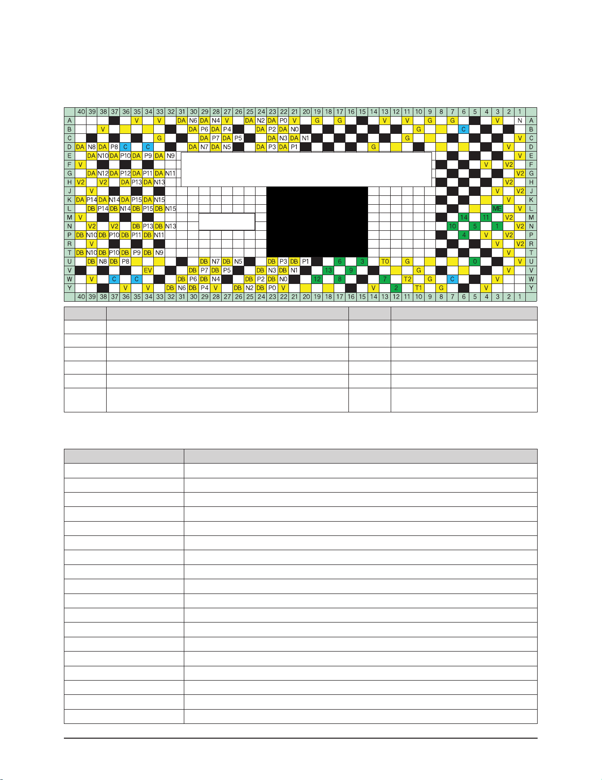
2-9-3 DMD Panel Pin Terminal Characteristics Diagram
2-9-4 Description of Terminal Characteristics
※ Remove the heat sink attached to the DMD Board and tighten the screws in four places and then inspect the characteristics of
each pin terminal.
Pin Name Description Pin Name Description
V Voltage : 3.3V T Test Point
V2 VCC2 : 8V ME Mirror Bias Extra
DA AChannel Data Bus [When measured, there should be a waveform] C Clock
DB B Channel Data Bus [When measured, there should be a waveform] P# A,B Channel Positive
No. MBRST# (Mirror Bias Rest) 26V N# A,B Channel Negative
G
The part from the present position to the GND
(The black part is also a GND.)
The vertical lines, which may occur due to improper connections between the panel and the
PCB, occur with intervals of 50 inches(26mm). If vertical lines occur with intervals of more than
26mms, it indicates a failure of the DDP1011 IC itself. If they occur with intervals of less than
26mm, it means that more than two pins have bad connections.
DA,DB output wave
[Screen:WHITE]
Page 23

Alignment and Adjustments
Samsung Electronics 2-19
No Description Key Point Remark
1
1) When the power cord is plugged in,
2) DC 380V is automatically supplied to the ballast.
Check whether the DC380V
power is supplied to the ballast.
2
1) When the power key is pressed via the remote control, the micom
of the digital board outputs high (5V) PWR signals.
2) The power board operates normally.
5V and 12V are supplied to the DMD CN105 terminal.
Check whether 5V and 12V are
supplied to the CN105 terminal.
* 12V must be supplied to operate the motor.
(The voltage of the motor driving power is 12V.)
3
1) The MTR Reset signal is supplied to the R161 terminal of the
motor IC101 from the micom on the digital board and then the
motor starts to drive.
2) If the color wheel rotates for a certain time and then stops, check
whether the color wheel sensor is normal.
(Check the waveform on the No.2 terminal below CN102.)
After the set is powered on, check
whether 5V is detected on pin
No.49 of IC101.
→ After a while, the sound
generated by the rotating color
wheel is heard.
* If 5V is not detected, the motor will not operate.
4
1) Check whether the signal (SCI: STARTCONTROL INPUT)
that turns on lamp #2 of CN109 on the DMD board is high (5V).
Check whether CN109 #2 signal
is 5V.
* When SCI is high (5V), the lamp litz of CN109
is low (0V).
* CN109 #2 terminal voltage changes to pulse
wave form 14 seconds after (for 50 inch TV)
the time that the voltage is 5V.
* When about 4 seconds have passed after
changing to pulse waveform, the screens are
displayed on the set.
5 1) Method for checking whether the DDP1010 IC RESET is normal.
If the voltage between R254 and
R255 is 3V, it is normal.
2-9-5 Engine Failure Inspection Flow Chart for the DMD Board
2-9-6 Output Voltage States of the DMD Board Parts
Output terminal
Wave form for
RA101,102,103,104
Page 24

Alignment and Adjustments
2-20 Samsung Electronics
2-10 Optical Science
2-10-1 Engine
2-10-2 Optical Specification
Parameter Nominal Value Unit Connent
Brightness 450 nits
6-segment color wheel, TI development board,
no spoke light recapture, reference lamp
Uniformity (ANSI)
- Typical
- Minimal
+/- 15
+/- 25
%
%
+ : brightest of 13 ANSI points/average of 9 points
- : darkest of 13 ANSI points/average of 9 points
Contrast full on/off
- Typical
1000 to 1 n.a.
6-segment color wheel, TI development board,
no spoke light recapture
Color Temperature 7,500 K (Warm 1) n.a. measured in image center
F-number
≥ 2.6
n.a. design value
Projection distance at 50"
screen size
680 mm
projection distance : distance from vertex of front
lens to projection screen
Exit pupil position 48.69 mm design value, distance to vertex of front lens
F.O.V (Field of View) 84 deg. design value
Panel size 17.5104x9.8496 mm Diamond Pixel Configuration
Lateral color aberration
@ 50" (R-G ; B-G)
≤ 7
≤ 7
㎛
㎛
Desion value
440/546/640 ㎛
TV distortion
- in horizontal direction
- in vertical direction
≤│0.3│
≤│0.3│
%
%
Pin Cushion or Barrel condition
folding angle 62 deg. mechanical design value
Lamp Module
Color Wheel Cover
DMD Module
Optical Module
Page 25

Alignment and Adjustments
Samsung Electronics 2-21
2-11 Service
2-11-1 Service Hint #1 - DMD Board Assy
2-11-2 Service Hint #2 - ColorWheel Assy
Problem : PIXEL DEFECT, VERTICALLINE
Solution : Change the DMD Board assembly
Problem : INCREASED NOISE
Solution : Change the Color wheel module
G
Page 26

Alignment and Adjustments
2-22 Samsung Electronics
2-11-3 Service Hint #3 - LAMP Assy
Problem : LOW BRIGHTNESS or No Power
Solution : Change the Lamp module
Page 27
Alignment and Adjustments
Samsung Electronics 2-23
2-12 Tilt the Screen
Remove the bottom cover.
Remove the cover of the
signal terminal.
Fix the safety switch on the right with tape
so that the set can be turned on after
removing the bottom cover.
Page 28

Alignment and Adjustments
2-24 Samsung Electronics
Remove the four screws on the upper and lower part
of the power board, and remove the whole assembly
without removing the cable.
Page 29

Alignment and Adjustments
Samsung Electronics 2-25
Place the power board on the back, and
keep the cables connected.
Remove the two screws on the left and the one screw
on the bottom right, without removing the engine.
※ Even when those screws are removed, the board
does not separate, it can be moved within the
adjustable range because there is a spring screw
at the center that holds it.
Fix the safety switch on the right with tape
so that the set can be turned on after removing
the bottom cover.
Page 30

Alignment and Adjustments
2-26 Samsung Electronics
Turn on the TV to send signals.
Then, adjust the screen position,
by holding both of the upper corners
of the DMD board.
※ When adjusting the screen, it is better for two people to work together.
On person should direct the picture position while the other person looks
at the screen.
※ The movement direction of the board and the picture are opposite.
- When the board is lifted upward, the screen descends down.
- When it is tilted to the left, the screen tilts to the right.
※ When the picture adjustment is completed:
First, tighten the two screws on the left of the DMD board
and then slowly tighten the one screw on the bottom right.
Be careful not to touch the board while screwing.
(When using an electric-powered screwdriver, be careful that
the torque is not too high.)
Page 31

Alignment and Adjustments
Samsung Electronics 2-27
2-13 Side Panel Buttons
The buttons on the right side panel control your TV's basic features, including the on-screen menu system. To use the more
advanced features, you must use the remote control.
2-14 Side Panel Jacks
Use the right side panel jacks to connect a component that is used only occasionally (a camcorder or video game, for example).
①
SOURCE
Press to switch between viewing TV programs and signals from connected
components.
②②
MENU
Press to see the on-screen menu.
③
+ VOL –
Press to lower or raise the volume and to select items when using the on-screen
menu.
④④ ∧
CH
∨∨
Press to change channels and move between items on the on-screen menu.
⑤
Press to activate (or change) a particular item.
⑥⑥
POWER
Press to turn the TV on and off.
①
VIDEO Input jack
Connect the video signal from a camcorder or video game.
②②
AUDIO Input jacks
Connect the audio signal from a camcorder or video game.
③
S-VIDEO Input jack
Connect an S-video signal from a camcorder or video game.
(S-Video 3 jack and Audio L/R input 3 are used in conjunction.)
Page 32

Alignment and Adjustments
2-28 Samsung Electronics
2-15 Rear Panel Jacks
Use the rear panel jacks to connect components such as a VCR. You can connect different components such as VCRs, Set-Top
Box and a DVD player etc., because there are two sets of video input jacks and two sets of component video input jacks on the
rear panel of your TV. For more information, please see "Connections".
① ANTENNAterminals
Two independent cables or antennas can be connected to these
terminals. Use "Cable IN" and "Air IN" terminals to receive a
signal from VHF/UHF antennas or your cable system. Use the
"Cable OUT" terminal to send the signal being received by the
"Cable IN" terminal out to another component (such as a Cable
Set-Top Box).
② S-VIDEO INPUT jacks
Connects an S-Video signal from an S-VHS VCR or DVD player.
③ DVI (Digital Video Interface) AUDIO INPUT jacks
Connect to the digital audio output jacks of a device with DVI
output.
④ VIDEO/AUDIO INPUT jacks
Connect video/audio signals from external sources, such as VCR
or DVD players.
⑤ VIDEO/AUDIO OUTPUT jacks
Sends video/audio signals from the TV to an external source,
such as a VCR. These jacks are available only in RF, Video and
S-Video modes.
⑥ Component1, 2 jacks (Y, PB, PR, L, R)
Use these jacks to connect the component video/audio signals
from a DVD player or a Set-Top Box.
⑦ DIGITALAUDIO OUT(OPTICAL) jack
Connect to a Digital Audio Component.
⑧ Anynet
Please refer to the Anynet Owner's Instruction.
⑨ HDMI (High Definition Multimedia Interface)/
DVI INPUT jack
Connect to the HDMI jack of a device with HDMI output.
Connect to the digital video output jack for device with DVI
output.
⑩ CableCARD™
Insert the CableCARD into the slot.
⑪ SERVICE
This jack is for repair and software upgrades.
Page 33

Alignment and Adjustments
Samsung Electronics 2-29
17.EXIT
Press to exit the menu.
18.▲, ▼, ◀, ▶, ENTER
Press to select highlight up, down, left, or
right. While using the on-screen menus,
press the ENTER to activate (or change) a
particular item.
19.MTS(Multichannel Television
Stereo
)
Press to choose Stereo, Mono or SAP
(Secondary Audio Program).
20.PIP(Picture In Picture)
Displays the available channels in
sequence.
(These buttons change channels in the PIP
window only.)
21.STILL
Press to pause the current screen.
22.ASPECT
Press to change the screen size.
23.SRS
Activates TruSurround.
24.DNIe
(Digital Natural Image engine)
Activates DNIe.
25.SET
Used during set up of this remote control, so
that it will work compatibly with other
devices.
(Set-Top box, VCR, Cable box, DVD, etc.)
26.SLEEP
Press to select a preset time interval for
automatic shutoff.
27.PIP Controls
CH ∧∧/
∨
; Press to displays the available
channels in sequence. (These buttons
change channels in the PIP window only.)
28.CAPTION
Controls the caption decoder.
29.VCR/DVD Controls
Controls VCR or DVD functions: Rewind,
Stop, Play/Pause, Fast Forward.
27.RESET
If your remote control is not functioning
properly, take out the batteries and press
the reset button for about 2~3 secons.
Re-insert the batteries and try using the
remote control again.
1. POWER
Turns the TV on and off.
2. P.MODE
Adjust the TV picture by selecting one of
the preset factory settings (or select your
personal, customized picture settings.)
3. ANTENNA
Press to select "AIR" or "CABLE".
4. CHANNEL NUMBER
Press to directly tune to a particular
channel.
5. -
Press to select additional channels
(digital and analog) being broadcast by
the same station. For example, to select
channel "54-3", press "54", then press
"-" and "3".
6. VOL+, VOL-
Press to increase or decrease the
volume.
7. MUTE
Press to mute the TV sound.
8. ANYNET
Runs the Anynet view functions and sets
up Anynet devices.
9. MENU
Displays the main on-screen menu.
10.CH.LIST
Displays the channel list.
11.FAV.CH (Favorite Channel)
Press to switch between your favorite
channels.
12.MODE
Selects a target device to be controlled
by the Samsung remote control (i.e., TV,
STB, VCR, CABLE, or DVD).
13.PRE-CH
Tunes to the previous channel.
14.SOURCE
Press to display all of the available video
sources (i.e., TV, Set-Top box, VCR,
DVD, DTV).
15.CH
Press to change channels.
Moves from one set of screen information to the next in TV Guide menu.
16.INFO
Press to display information on the TV
screen.
2-16 Remote Control
You can use the remote control up to about 23 feet from the TV. When using the remote control, always point it directly at the TV.
You can also use your remote control to operate your VCR, Cable box, DVD player or Samsung Set-Top Box.
Page 34

2-30 Samsung Electronics
MEMO
Page 35

Troubleshooting
Samsung Electronics 3-1
3. Troubleshooting
3-1 Flow Chart for Malfunction
If the DLP turns on
No
Check the Power Cord
Yes
Can you see anything
in the screen?
No
Yes
Can you see OSD menu
running in the screen?
Check Cables connected to
Digital Board. If necessary,
replace Digital Board
Yes
No
Can you see Digital
Channel broadcast ?
No
Replace POD Channel Board
Does the LAMP turn on?
No
2)
Check if LED1 on the
Analog Board turns on?
Yes
Replace LAMP
Check Cables connected to
BALLAST. If necessary,
replace BALLAST.
Check Cables connected to
DMD Board.
If necessary, replace DMD Board.
Yes
1)
Check DVI Cable.
If necessary, replace DVI Cable.
No
3)
Check if DMD Fan is running?
Check Cables connected to
Power Board. If necessary,
replace Power Board.
No
Check Cables connected to
DMD Board. If necessary,
replace DMD Board.
Yes
Check Cables connected to
Analog Board.
If necessary, Analog Board.
1) DVI Cable
2) LED1
3) DMD Fan
Page 36

Troubleshooting
3-2 Samsung Electronics
3-2 Front Panel LED Indicators
The three lights on the front panel indicate the status of your TV.
• It takes about 30 seconds for the TV to warm up, so normal brightness may not appear immediately.
• The TV has a fan to keep the inside lamp from overheating. You'll occasionally hear it working.
Indicator Light Key
: Light is On
: Light is Blinking
: Light is Off
TIMER LAMP STAND BY/TEMP
Standby state.
The picture will automatically appear in about 15 seconds.
Auto Timer ON/OFF has been set and the set will automatically be
turned on in about 25 seconds.
A cooling fan inside the set is not operating normally.
Lamp cover on rear of the set is not properly shut.
Check if the ventilation hole on the rear of the set is blocked, because
if the inner temperature is too high, the power will shut off.
Lamp may be defective. Please contact a certified technician.
Indication
Page 37

Troubleshooting
Samsung Electronics 3-3
3-3 Blinking Temp & Timer LED
Are fans running?
No
Check for 8Vdc at
CN103 & 104 on Actuator
Board
No
Check CN802 pins 8&10 on
the Power board for 12VB
Yes
Replace
the Analog board
Yes
Replace Actuator board
Yes
Replace fan(s)
No
Replace Power Board
Page 38

Troubleshooting
3-4 Samsung Electronics
3-4 Blinking Temp LED
CN106
Temperature
Sensor
Ablinking lamp LED is the most common failure indication. It can be caused by no lamp, no color wheel, no
fan(s), or other defective components.
CN106
Check Temp Sensor
connector CN106
on Sub Detector Board
Yes
Install jumper across
Temp Sensor Terminals
Does it work?
Yes
Replace Temp. Sensor
No
No
Reinsert
the Connector
Replace
Sub Detector Board
Temperature
Sensor
Yes
Yes
Does color wheel run?
No
Yes
Yes
Yes
Is lamp on?
Does lamp
No
come on, then
shut off?
No
Yes
No
Replace DMD Board
Do fan(s) run?
Replace color wheel assy'
Check 280V DC to lamp ballast(CN1)
Measure with DC meter
No
Replace Power Board Re-install lamp assy'
No
Check pin 1 on CN503
on DMD Board for 5V DC
No NoYes Yes
Check 5Vpp at CN503
pin 3 on DMD Board
Replace lamp assy' or ballast Replace DMD Board Replace ballast or lamp assy'
Page 39

Troubleshooting
Samsung Electronics 3-5
3-5 Blinking Lamp and Temp LEDs
Is lamp cover installed?
Make sure lamp cover
switch is activating
Yes
Short CN107
on Actuator Board
No
Install lamp cover
Yes
No
Check boss
on Lamp Cover
No
Replace the Actuator Driver Board
No
Replace the Digital Board
CN107
Page 40

Troubleshooting
3-6 Samsung Electronics
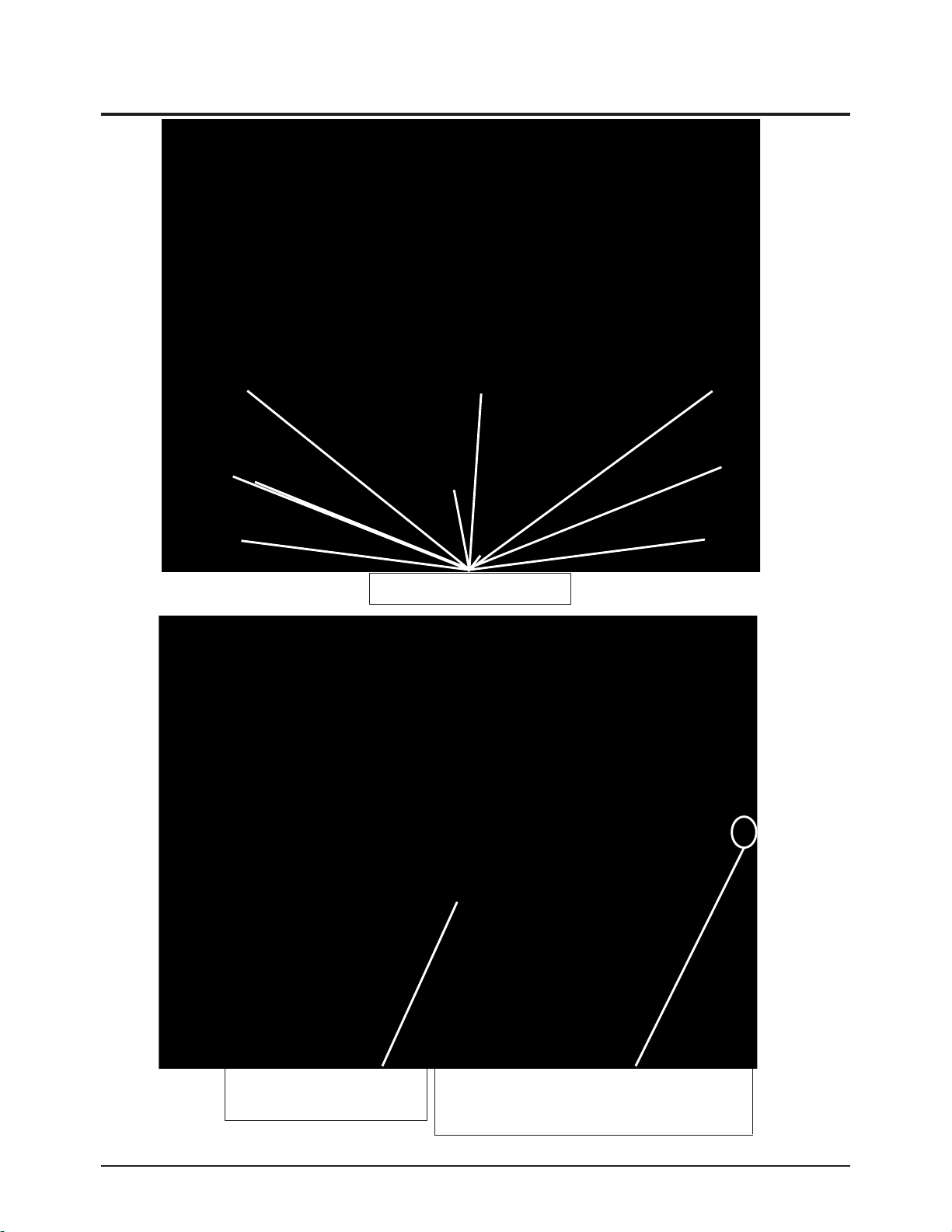
3-6 Disassemble and Reassemble
① Remove screws and back cover.
③ Separate a GT-Wire and DVI cable.
⑤ Chassis.
② Remove the screws and the terminal.
④ Separate the cables.
3-6-1 Separation of the back cover and the chassis
Page 41

Troubleshooting
Samsung Electronics 3-7
① Remove the screws and cables.
③ Analog, Digital Board and Fan.
⑤ Remove the nuts.
② Remove the screws and cables.
④ Remove the nuts.
⑥ Remove the screws.
3-6-2 Separation of the Analog and Digital Board
Page 42

Troubleshooting
3-8 Samsung Electronics
⑦ After removing a Top Shield case.
① Remove the screws and cables.
② Power Board.
3-6-3 Separation of the Power Board
Page 43

Troubleshooting
Samsung Electronics 3-9
* For replacement, you will need a 5.91 Inches-long Phillips screwdriver and a pair of gloves.
1. Unplug TV, then use a screwdriver to remove
the screw as shown in the picture.
(Remove the rubber cap and unscrew the
screw. )
2. Remove the Lamp cover.
(Exert a bit of force to the right and pull for easy
opening.)
3. Use a screwdriver to remove the screws
securing the Lamp.
There are 2 screws: one on the left and one on
the right. When the screws have been
completely unfastened, they will still be
connected to the body of the Lamp.
4. Separate the Lamp from the engine by holding
the handle and pulling it out.
5. To reinstall the Lamp, follow these steps in
reverse order.
☞ NOTES
1. Be sure the replacement Lamp is the same model.
2. After replacing the lamp align the lamp cover with the groove and secure the screw.
3. The TV will not turn on if the lamp cover is not correctly closed (as this will activate the protective circuit).
3-6-4 Lamp Replacement
Page 44

Troubleshooting
3-10 Samsung Electronics
3-6-5 BALLAST replacement Method
■ Failure type : The lamp does not operate.
1. Loosen the two screws which hold the lamp in place, and then remove the lamp.
2. Loosen the screw which holds the connector in place.
3. Loosen the four screws on the ballast board.
4. Replace it with a new board and re-assemble it in the reverse order.
1
2
3
4
Page 45

Troubleshooting
Samsung Electronics 3-11
3-6-6 Color Wheel Ass'y Replacement
1. Remove the three screws
2. Remove the dust preventing tape.
3. Lift up the C/W
cover.
Loosen the two screws
and remove the lamp.
Page 46

Troubleshooting
3-12 Samsung Electronics
Remove the five screws.
Lift up the bracket and the light tunnel.
※ Be careful not to dirty the light tunnel with foreign materials.
Remove the screw
at the side of the
light tunnel.
Remove the three screws
and replace the
color wheel ASSY.
*Caution: Never touch the color wheel.
Touch only the instruments.
Page 47

4. Exploded View & Parts List
4-1 HLR4677WX/XAA
Exploded View & Parts List
Samsung Electronics 4-1
You can search for the updated part code through ITSELF web site.
URL : http://itself.sec.samsung.co.kr
Loc.No. Code No. Description;Specification Q'ty S.N.A
M0256 BP96-00849D ASSY BRACKET P-MAIN PCB;L5,SECC,T1.0,SEA 1 S.N.A
T0003 BP96-00321E ASSY COVER P-FRONT;46L5(L62B),AL EXTR,DG 1
T0053 BP67-00051A SCREEN FRESNEL;46W,PMMA,1021*580.5,2T 1
T0054 BP67-00107A SCREEN LENTI;46W,MS,1021*580.5,2T 1
T0066 AA96-20129A ASSY POWER CORD;-,EP2/YES,H/C300,ME301P, 1 S.N.A
T0068 BP61-00337A BRACKET-MIRROR ASSY;SECC,46L5 1 S.N.A
T0070 BP61-00899A HOLDER-CHASSIS;HLP4674W,ABS V0,T2.5,W60, 1 S.N.A
T0074 BP59-00076A REMOCON;ROBOCOP,TM76A,200*54*21,47,Light 1
T0120 BP94-02141P ASSY PCB POWER; 1 S.N.A
T0129 BP96-00305P ASSY ENGINE P-DLP PL46;46L5 DLP,PHILIPS 1
T0130 BP96-00947A ASSY COVER P-TERMINAL BOARD;L5(L64A),HIP 1 S.N.A
T0131 BP96-00324C ASSY COVER P-BACK TOP;46L5,HIPS,V0,GRY,D 1
T0131 BP96-00328A ASSYCOVER P-BACK BOT;46L5,HIPS,V0,GR503 1
T0134 BP67-00040A MIRROR-FRONT,DM1;43",GLASS,810*472*434,F 1
T0132 BP94-01853A ASSY PCB MISC-DIGITAL;HLR4677WX/XAA,L64A 1 S.N.A
T0137 BP94-02211A ASSY PCB S-SUB DETECTOR S/W;HLP4674WX/XA 1 S.N.A
T0145 BP94-02037A ASSY PCB MISC-ANALOG;HLR4677WX/XAA,L64A, 1 S.N.A
T0147 BP96-00325G ASSY COVER P-SIDE L;46L5,HIPS,HB,GRY,DGM 1
T0158 BP96-00322J ASSY COVER P-MAIN;46L5(L64A),HIPS,V0,GRY 1 S.N.A
T0177 BP63-00072B COVER-FRONT JERSEY;46L5,AL6063,BLK,EXTR 1 S.N.A
T0186 BP96-00431B ASSYCOVER P-GRILLE HOLE;46L5,HIPS,HB,GR 1
T0211 BP61-00383A BRACKET-SCREEN BOT;46L5,AL 6063 EXT,BLK 1 S.N.A
T0214 BP63-00144S COVER SIDE-R ASSY;46L5,HIPS,HB,GRY,DGM12 1 S.N.A
T0264 AA63-00021G SPACER-MIRROR;524J,434J,PVC,-,-,-,BLK,-, 3 S.N.A
T0265 AA63-00021U SPACER-MIRROR BOT;47Q7,PVC HB,L770,BLK 1 S.N.A
T0409 BP61-00338A BRACKET-FRONTTOP ASSY;AL6063,46L5,EXTR, 1 S.N.A
T0890 BP96-00855A ASSY FAN P;1B1S,50*50*0.5,1.9,0.19,24,-1 1 S.N.A
T0928 BP61-00259A BRACKET-MIRROR TOP(T);46L5,AL6063,BLK,EX 1 S.N.A
T0074 T0066
T0053
T0003
T0211
T0186
T0054
T0928
T0177
T0264
T0265
T0068
T0134
T0409
T0158
T0147
T0129
T0070
T0137
T0132
T0120
T0131
T0890
T0145
T0214
M0256
T0131
T0130
Page 48

Exploded View & Parts List
4-2 Samsung Electronics
4-2 HLR5677WX/XAA
You can search for the updated part code through ITSELF web site.
URL : http://itself.sec.samsung.co.kr
Loc.No. Code No. Description;Specification Q'ty S.N.A
M0256 BP96-00849D ASSY BRACKET P-MAIN PCB;L5,SECC,T1.0,SEA 1 S.N.A
T0003 BP96-00300C ASSY COVER P-FRONT;56L5,AL EXTR,DGN8422, 1
T0053 BP67-00155A SCREEN FRESNEL;56W,1257*713.5,2T 1
T0054 BP67-00110A SCREEN LENTI;56W,MS,1257*713.5,2T 1
T0066 AA96-20129A ASSY POWER CORD;-,EP2/YES,H/C300,ME301P, 1 S.N.A
T0068 BP61-00305A BRACKET-MIRROR ASSY;BLK,56L5 1 S.N.A
T0070 BP61-00899A HOLDER-CHASSIS;HLP4674W,ABS V0,T2.5,W60, 1 S.N.A
T0074 BP59-00076A REMOCON;ROBOCOP,TM76A,200*54*21,47,Light 1
T0120 BP94-02141P ASSY PCB POWER; 1 S.N.A
T0129 BP96-00305P ASSY ENGINE P-DLP PL46;46L5 DLP,PHILIPS 1
T0130 BP96-00947A ASSY COVER P-TERMINAL BOARD;L5(L64A),HIP 1 S.N.A
T0131 BP96-00299A ASSYCOVER P-BACK BOT;56L5,HIPS,V0,GR503 1
T0131 BP96-00302B ASSY COVER P-BACK TOP;56L5,HIPS V0,GRY,D 1
T0132 BP94-01853A ASSY PCB MISC-DIGITAL;HLR4677WX/XAA,L64A 1 S.N.A
T0137 BP94-02211A ASSY PCB S-SUB DETECTOR S/W;HLP4674WX/XA 1 S.N.A
T0145 BP63-00122P COVER SIDE-RIGHTASSY;56L5,HIPS,HB,GRY,D 1 S.N.A
T0145 BP94-02037A ASSY PCB MISC-ANALOG;HLR4677WX/XAA,L64A, 1 S.N.A
T0147 BP96-00303G ASSY COVER P-SIDE L;56L5,HIPS,HB,GRY,DGM 1
T0158 BP96-00297M ASSY COVER P-MAIN;56L5,HIPS,V0,GRY,SEA(L 1 S.N.A
T0186 BP96-00432B ASSYCOVER P-GRILLE HOLE;56L5,HIPS,HB,GR 1
T0260 BP67-00059A MIRROR-FRONT;Mirror Front 56",glass,1048 1
T0264 AA63-00021L SPACER-MIRROR,TOP;50J6,PVC HB,BLK,L1020 1 S.N.A
T0264 AA63-00021N SPACER-MIRROR,SIDE;50J6,PVC HB,L545,BLK 3 S.N.A
T0409 BP61-00382A BRACKET-FRONT TOPASSY;AL6063+ABS,56L5 1 S.N.A
T0890 BP96-00855A ASSY FAN P;1B1S,50*50*0.5,1.9,0.19,24,-1 1 S.N.A
T0925 BP61-00384A BRACKET-SCREEN HOLE;AL6063 EXTR BLK,56 1 S.N.A
T0927 BP63-00149A COVER-FRONT HOLE;56L5,AL6063 EXTR BLK 1 S.N.A
T0928 BP61-00223A BRACKET-MIRROR TOP(T);46L5,AL6063,BLK,EX 1 S.N.A
T0074 T0066
T0409
T0068
T0928
T0927
T0264
T0264
T0260
T0158
T0054
T0053
T0003
T0925
T0186
T0147
T0129
T0070
T0137
T0132
T0120
T0131
T0890
T0145
T0145
M0256
T0131
T0130
Page 49

Exploded View & Parts List
Samsung Electronics 4-3
Exploded View & Parts List
4-3 ENGINE ASS'Y
L3 Engine Exploded View List
NO. Description CODE NO. Specification Q'TY
1 ASSY LAMP P BP96-00826A L3,LAMPSERVICE,PHILIPS 120W,E22 1
1-1 SCREW-MACHINE 6006-001039 WSP,PH,+,M4,L12,ZPC(YEL),SM10C 1
2 ASSY DMD BOARD P BP96-00678B L3 PHILIPS,DMD BOARD,SERVICE 1
2-1 SPRING ETC-COIL,DMD AA61-01195A B3K,SPRING STEEL 4
2-2 SCREW-MACHINE 6001-000819 PWH,+,-,M3,L30,ZPC(YEL),SWRCH10A,UP,- 4
2-3 SCREW-TAPTITE 6006-000248 PWH,+,-,S,M3,L8,ZPC(YEL),SWRCH18A,P0 2
2-4 SCREW-TAPTITE 6003-000264 PWH,+,B,M3,L6,ZPC(YEL),SWRCH18 1
3 ASSY BALLAST P BP96-00690A L3,SERVICE BALLST 1
3-1 SCREW-TAPTITE 6003-001023 PWH,+,B,M3,L10,ZPC(YEL),SWRCH18A,- 2
4 ASSY K/D-COLOR WHEEL BP98-00489A L3 ENGINE,SERVICE 1
5 ASSY K/D-OPTIC MODULE BP98-00490B L3 ENGINE(FDB),SERVICE 1
5-1 SCREW-TAPTITE 6003-000277 BH,+,B,M3,L12,ZPC(YEL),SWRCH18 5
6 COVER DUCT-TOP23 BP63-00295A SVP-50L3HR,PC G/F20 1
6-1 COVER DUCT-BOTTOM23 BP63-00296A SVP-50L3HR,PC G/F20 1
6-2 FAN-DC BP31-00010B SVP-50L7XHD,UL94V-0, PBT,Wire Length = 500mm 1
6-3 RUBBER-FAN,LAMP BP73-00012A SHP700,NBR,50,LOSS FACTOR>0.02 2
6-4 SCREW-TAPTITE 6003-001023 PWH,+,B,M3,L10,ZPC(YEL),SWRCH18A,- 3
6-5 SCREW-MACHINE 6006-001039 WSP,PH,+,M4,L12,ZPC(YEL),SM10C 3
7 GUIDE-BALLAST 23 BP61-00732A SVP-50L3HR,PC G/F 20 1
7-1 HOLDER-BALLAST 23 BP61-00728A SVP-50L3HR,PC G/F20 1
7-2 SCREW-MACHINE 6006-001039 WSP,PH,+,M4,L12,ZPC(YEL),SM10C 3
8 HOUSING-LAMP,BOTTOM 23 BP61-00726A SVP-50L3HR,AL D/C 1
8-1 SCREW-TAPTITE 6006-000249 PWH M/S (S.P/W) M3*L7 P0.75 3
9 ASSY MISC-THERMOSTAT BP91-00612A HLP5063W,L62B 1
9-1 SCREW-MACHINE 6006-001035 PH M/S (S.P/W) M3*L8 P0.5 2
10 COVER-CW 23 BP63-00299A SVP-50L3HR,PC G/F20 1
10-1 SCREW-MACHINE 6006-001035 PH M/S (S.P/W) M3*L8 P0.5 2
11 COVER-LENS PROJECTION BP63-00338A SVP-50L3,PS,T0.3 1
11-1 SCREW-TAPTITE 6003-001023 PWH B-T M3*L10 2
12 HOLDER-INTERFACE BP61-00668A SVP-50L3HR,ABS V0 BLK 1
12-1 SCREW-MACHINE 6006-001039 WSP,PH,+,M4,L12,ZPC(YEL),SM10C 3
12-2 ASSY PCB S-ACTUATOR BP94-02149K DP,BP41-00121A,L62B,ATLANTIS 1
12-3 SCREW-TAPTITE 6003-001023 PWH B-T M3*L10 4
12-4 ASSY MISC-DETECTOR S/W BP91-00775A ASSY MISC-DETECTOR S/W 1
12-5 SCREW-TAPTITE 6003-001023 PWH B-T M3*L10 1
13 BRACKET-BASE 23 BP61-00730A SVP-50L3HR,SECC,1.6 1
14 HOLDER-BASE BP61-00590A DLP L3,PPS G/F30 1
14-1 SCREW-MACHINE 6006-001039 WSP,PH,+,M4,L12,ZPC(YEL),SM10C 6
15 FAN-DC BP31-00011A AD0612LB-D72GL,P.B.TUL94-Vo,Wire+Metal Bracket 1
15-1 BRACKET-FAN DMD BP61-00595A DLP L3,SECC,T1.0 1
15-2 SCREW-TAPTITE 6006-000250 BH,+,WT,B,M3,L20,ZPC(YEL),SWRCH18A,- 2
15-3 SCREW-TAPTITE 6003-000199 PWH,+,B,M3,L14,ZPC(YEL),SWRCH1 2
15-4 HOLDER-SPACER,RUBBER BN61-00236A B3K,BSBM 2
15-5 RUBBER-DAMPFAN BP73-00040A HLN507W,CR,30,BLACK,V0 2
3
2-
2
2-1,2-
4
2-
12
15
15-1
15-2
15-3
15-4
5
15-
1
11-
1
1
1
5
42
12-
12-1
12-4
2
1-1
12-
5-
6-
1
0
1
10-
1
4
4
6
3
6-
2
6-
1
6-
14-
5
1
6-
12-3
9
1
9-
8
8-
1
5
3
7-2
13
7-1
1
1
3-
Page 50

Electrical Parts List
Samsung Electronics
5-1
5. Service Item
5-1 HLR4677WX/XAA
Yon can search for the updated part code through ITSELF web site.
URL:http://itself.sec.samsung.co.kr
Loc.No. Code No. Description;Specification Q'ty
D0254 AA32-00015A MODULE REMOCON;FRP-3521H31,38KHZ,940MM,M 1
T0268 AA39-10007Y CBF-POWER CORD;-,EP2/YES,SPT-2 18AWGx2C, 1
CIS3 AA40-00122A TUNER;TMQH2-003A,C-TV TM(SUB),NTSC,181CH 1
T0952 AA59-00365A MODULE-RF SPLITTER;UMX-NT-040,2in/2out/l 1
M0114 BP39-00106E CBF SIGNAL;HLP4674WX,24P/24P,UL20276-D,4 1
T0049 BP47-00016A LAMP-BALLAST;EUC 120 P/H 11,120W P/H 11, 1
T0074 BP59-00076A REMOCON;ROBOCOP,TM76A,200*54*21,47,Light 1
T0453 BP61-00244A HOLDER-BALLAST PHILIPS;PPS,NATURAL 1
T0269 BP64-00225A CABINET-BACK BOT;46L5,HIPS,V0,GRAY 1
T0268 BP64-00226A CABINET-BACK TOP;46L5,HIPS,V0,GRAY 1
T0134 BP67-00040A MIRROR-FRONT,DM1;43",GLASS,810*472*434,F 1
T0053 BP67-00051A SCREEN FRESNEL;46W,PMMA,1021*580.5,2T 1
T0512 BP67-00093A LENS-PRJ ASSYVE;HLN507W1X,GLASS,NTR,N/A 1
T0054 BP67-00107A SCREEN LENTI;46W,MS,1021*580.5,2T 1
T0511 BP68-00460A MANUAL USERS;HL-R4677W,SEM,ENG,C.S. Amer 1
T0091 BP94-00502S ASSY PCB MISC-SIDE A/V;HLN467WX/XAA,L62A 1
T0132 BP94-01853A ASSY PCB MISC-DIGITAL;HLR4677WX/XAA,L64A 1
T0145 BP94-02037A ASSY PCB MISC-ANALOG;HLR4677WX/XAA,L64A, 1
T0120 BP94-02141P ASSY PCB POWER; 1
T0245 BP94-02203A ASSY PCB MISC-KEY CONTROL;HLP4674WX/XAA, 1
T0175 BP96-00076A ASSY SPEAKER P;,8OHM,25W,001282/001144,1 1
T0128 BP96-00224C ASSY COVER P-LAMP(PJ);43"50"46"56" DLP P 1
T0127 BP96-00249F ASSY COVER P-DMD;L5(L62B),SVC ASSY 1
T0126 BP96-00250A ASSY COVER P-COLOR WHEEL;DLP(SVC),COLOR 1
T0296 BP96-00251A ASSY COVER P-DUCT FAN;DLP(SVC),FAN ASSY 1
T0129 BP96-00305P ASSY ENGINE P-DLP PL46;46L5 DLP,PHILIPS 1
T0003 BP96-00321E ASSY COVER P-FRONT;46L5(L62B),AL EXTR,DG 1
T0158 BP96-00322J ASSY COVER P-MAIN;46L5(L64A),HIPS,V0,GRY 1
T0131 BP96-00324D ASSY COVER P-BACK TOP;46L5,HIPS,V0,GR503 1
T0147 BP96-00325G ASSY COVER P-SIDE L;46L5,HIPS,HB,GRY,DGM 1
T0131 BP96-00328A ASSY COVER P-BACK BOT;46L5,HIPS,V0,GR503 1
T0186 BP96-00431B ASSY COVER P-GRILLE HOLE;46L5,HIPS,HB,GR 1
CN269 BP96-00547C ASSY BOARD P-JACK;ROBOCOP_1,NTSC,AV+S.VH 1
M0018 BP97-00873A ASSY MICOM;L62B,29W800D,T-AT2MWWS-1001,0 1
Page 51

Electrical Parts List
5-2
Samsung Electronics
5-2 HLR5677WX/XAA
Yon can search for the updated part code through ITSELF web site.
URL:http://itself.sec.samsung.co.kr
Loc.No. Code No. Description;Specification Q'ty
D0254 AA32-00015A MODULE REMOCON;FRP-3521H31,38KHZ,940MM,M 1
T0268 AA39-10007Y CBF-POWER CORD;-,EP2/YES,SPT-2 18AWGx2C, 1
CIS3 AA40-00122A TUNER;TMQH2-003A,C-TV TM(SUB),NTSC,181CH 1
T0952 AA59-00365A MODULE-RF SPLITTER;UMX-NT-040,2in/2out/l 1
M0114 BP39-00106E CBF SIGNAL;HLP4674WX,24P/24P,UL20276-D,4 1
T0049 BP47-00016A LAMP-BALLAST;EUC 120 P/H 11,120W P/H 11, 1
T0074 BP59-00076A REMOCON;ROBOCOP,TM76A,200*54*21,47,Light 1
T0453 BP61-00244A HOLDER-BALLAST PHILIPS;PPS,NATURAL 1
T0269 BP64-00212A CABINET-BACK BOT;56L5,HIPS,V0,,,,,GRAY, 1
M0045 BP64-00213B CABINET BACK-TOP;56L5,HIPS,V0,GRAY,DGM-1 1
T0260 BP67-00059A MIRROR-FRONT;Mirror Front 56",glass,1048 1
T0512 BP67-00093A LENS-PRJ ASSYVE;HLN507W1X,GLASS,NTR,N/A 1
T0054 BP67-00110A SCREEN LENTI;56W,MS,1257*713.5,2T 1
T0053 BP67-00155A SCREEN FRESNEL;56W,1257*713.5,2T 1
T0511 BP68-00460A MANUAL USERS;HL-R4677W,SEM,ENG,C.S. Amer 1
T0091 BP94-00502S ASSY PCB MISC-SIDE A/V;HLN467WX/XAA,L62A 1
T0132 BP94-01853A ASSY PCB MISC-DIGITAL;HLR4677WX/XAA,L64A 1
T0145 BP94-02037A ASSY PCB MISC-ANALOG;HLR4677WX/XAA,L64A, 1
T0120 BP94-02141P ASSY PCB POWER; 1
T0245 BP94-02203A ASSY PCB MISC-KEY CONTROL;HLP4674WX/XAA, 1
T0175 BP96-00076A ASSY SPEAKER P;,8OHM,25W,001282/001144,1 1
T0128 BP96-00224C ASSY COVER P-LAMP(PJ);43"50"46"56" DLP P 1
T0127 BP96-00249F ASSY COVER P-DMD;L5(L62B),SVC ASSY 1
T0126 BP96-00250A ASSY COVER P-COLOR WHEEL;DLP(SVC),COLOR 1
T0296 BP96-00251A ASSY COVER P-DUCT FAN;DLP(SVC),FAN ASSY 1
T0158 BP96-00297M ASSY COVER P-MAIN;56L5,HIPS,V0,GRY,SEA(L 1
T0131 BP96-00299A ASSY COVER P-BACK BOT;56L5,HIPS,V0,GR503 1
T0003 BP96-00300C ASSY COVER P-FRONT;56L5,AL EXTR,DGN8422, 1
T0131 BP96-00302B ASSY COVER P-BACK TOP;56L5,HIPS V0,GRY,D 1
T0147 BP96-00303G ASSY COVER P-SIDE L;56L5,HIPS,HB,GRY,DGM 1
T0129 BP96-00305P ASSY ENGINE P-DLP PL46;46L5 DLP,PHILIPS 1
T0186 BP96-00432B ASSY COVER P-GRILLE HOLE;56L5,HIPS,HB,GR 1
CN269 BP96-00547C ASSY BOARD P-JACK;ROBOCOP_1,NTSC,AV+S.VH 1
M0018 BP97-00873A ASSY MICOM;L62B,29W800D,T-AT2MWWS-1001,0 1
Page 52

Block Diagram
Samsung Electronics 6-1
6. Block Diagram
6-1 Digital Block Diagram
S
O
U
U
T
o
g
S
o
a
u
e
(
)
PO
slo
t
o
d
(
s
m
igl
Page 53

Block Diagram
6-2 Samsung Electronics
6-2 DLP-Builtin Module
X226
MP
UNE
nnel
400
400
DN
LVD
MD_
ntr
MEMO
(1
B)
128
AUD
PCMCIA
Cable Card
POD Channel
(NT &AT SC& QAM)
TUNE
R
#2
TS_1_DATA[ 7:0]
CLK,VLD,SY
(NT )
TUNER SIGNAL
M_CVBS
S_CVBS
M_SIF
S_SIF
VIDEO-1
3D-Y
3D-C
VIDEO-2
SUB-V/Y
SUB-C
Componet-1
COMP1_Y
COMP1_Pb
COMP1_Pr
Componet-2
COMP2_Y
COMP2_Pb
COMP2_Pr
HDMIRx
RS-232
MICOM_Rx
MICOM_Tx
RS-232(Debug)
Rx
Tx
TMDS
COMP1 Y,Pb,Pr
COMP2 Y,Pb,
TMDS
Scramle TS UN Scramle TS
NC
TS_2_DATA[7:0]
CLK,VLD,SYNC
Pr
HDMI
Sii9993
HDMI Rx
M
CImax
U
X
Card I/F
M
U
X
3D- Y/C
SUB- Y/C
VBS
S_C
COMP1 Y,Pb,Pr
COMP2 Y,Pb,
BA7657
7657
COM P
Y,Pb,
S/ W
M
U
X
M
U
X
M
U
X
M
U
X
Pr
Pr
3D- Y/C
SUB- Y/C
S_CVBS
7657 Y,Pb,
PC R,G,B,
HSYNC,VSYNC
I2C_M
SDA_M5
SCL_M5
Pr
TS_A_DATA[ 7:0]
CLK,VLD,SYNC
TS_B_DATA[ 7:0]
CLK,VLD,SYNC
ADV7400
#2
(NT & ADC)
ADV7400
#1
(NT & ADC)
I2C
SDA_PANNEL
NNEL
SCL_PA
MUX
656[7 :0] ,CLK
LK
656[7 :0] ,C
or
24bit[ 7:0],CLK ,
c
HSync,Vsyn
DE
HDMI_I2S_CLK,
CLK
DATA,LR
AUDIO
I2S_CLK,DATA,LRCLK
NT_I2S_CLK,
DATA,LRCLK
TS #A
TS #B
&
Ext
VIDEO
IN #A
Ext
VIDEO
IN #B
FLFLASH
(16MB)
28F128
(CPCPU
MP
Ext
AUDI
IN
MUX
K4D551638Dx2
X226
B
&
EG.G.decode r
&
Video Scaler
&
OSD )
RS- 232 A
O
RS- 232 B
NT_I2S_CLK ,
DATA,L RCLK
RARAM
MB)
(128
Digital
AUDIO
AC 3/PCM
OUT
MICOM_Rx, Tx
OUT
OUT
12bit
[11:0]
CLK 0
Rx,Tx
CONTROL
CPU_RESET
12bit[24:12]
H,VSYN C,CL K 1
D-Flip
-Flo p
AC 3/PCM
OUT
MEMO
K4S643232 x
DN
Enhanc
12bit
[11:0]
I2S_CL K,DATA
LRC LK
6MB)
(1
Ie Pro
Image
OPT ICAL
I2C_5V
RY
2
24bit
[23:0]
H,VSYNC ,
er
CLK
/RCA
LVD
S &
Contr
MD_
TX[3:0]+DLP_SYNCVAL
MD_nRESET
DDP_READY
PWRGOOD
LVDS_EN
LAMP+Txn,Rx
SDA,SCLPANNEL
AUD
SPDIF
SDA_M5
SCL_M5
ol
IO
THC 63LVDH63
LVDS Tx
Page 54

Block Diagram
Samsung Electronics 6-3
6-3 Analog Block Diagram
278
RA0
278
RA0
317SX-ADAD
(1
2VB
DCDC
(12
.3
VB-D)
317SX-ADAD
(12
Si
2.0mm
2.0mm
30p,#2
6
7p,#26
2.0mm
4p,#26
2.0mm
6p,#
190mm
26
2.0mm
3p,#
2.0mm
26
30p,#2
6
2.5mm
p,#26
30
2
3
0
m
m
2.0mm
5p,#
26
U
p
g
r
a
d
e
KA78RH33
(5V→3.3V)
LF25C
(5V→2.5V)
LM317SX-
(1
2VB
→ 9VBVB)
Regulator
LF25
D-to-A (2R)
(AV Signals
KEY
for L7
)
KEY
Micom
Block
Micom/EPG Slicer
DA555X)
(S
J
Video Switching(Y/C, Adder)
3D Comb
Block
& LED
LM317SX-
(12
PWR
VA- >9VAVA)
I/O Expander
(PCF8574)
de AV
Si
Regulator
78D05F
IR
J
D-to-A (2R) D-to-A (2R)
(Control Sign
DCDC
(12
VB- >3.3
VB-D)
als)
DCDC
(12VA->6.5VA-D)
Speaker
Sound Amp Block
ReRegugulator
(278
RA0
5)
ReRegugulator
(278
RA0
MSP4440
Audio Processing
(Power)
DCDC
12VA->3.3V-ATI
5)
(
S
P
T
B
)
(
B
+
)
DMD
PWR
D
E
U
T
°
B
W
R
P
O
W
E
R
S
2.5mm
10
p,#22
2.5mm
24
p,#22
2.0mm
9p,#
2.0mm
10p,#26
26
)
Regulator
BA033
2.0mm
3p,#26
Video Switching(CVBS)
Analog Board
(Built-In)
Audio Switching
I/O Expander
(PCF8574)
(SVHS1/SVHS2)
FAN
AV INPUT/OUTPUT
(V1/V2/V out)
Component1/2
Page 55

Block Diagram
6-4 Samsung Electronics
6-4 RF SWITCH POD LNA BLOCK
6-5 AV Switching(TEA64XX) BLOCK
TEA64
Y/C
TEA64
Video
3D-COMB
TEA64
Mixer
TEA64
Audio
MSP44X
B+(9V)
LNA
S/
W#1
GND
S/W#2
AIR
CABLE LOOP OUT
LNA
SPLIT
RELAY#1
RELAY#2
MAIN SUB
CABLE
BS S/W OFF
LOOP
AMP
SPLIT
SVHS1-Y
SVHS1-C
SVHS2-Y
SVHS2-C
3D-Y
3D-C
MTNR-V
STNR-V
V1-V
V2-V
N.C
SIDE-V
V1-LR
V2-LR
N.C
SIDE-LR
COMP1- LR
COMP2- LR
TEA64
(ADDER
Tri-State)
(96h)
Y/C
TEA64
(ADDER
Tri-State)
(90h)
Video
TEA64
(98h)
Audio
25
SW
25
SW
22
SW
MAIN-V- OUT
SUB
CAP-V-OUT
MON-V-OUT
MAIN-Y- OUT
MAIN-C-OUT
SUB-Y-OUT
SUB-C-OUT
-V-OUT
MAIN-LR
SUB- LR
PC
DVI-LR
3D-C
3D-Y
3D-COMB
-LR
SIDE-Y
SIDE-C
MSP44X
MAIN-Y
MAIN-C
TEA64
(ADDER
Tri-State)
(94h)
Mixer
25
SW
+
+
SUB- V(MIXED)
CAP-V(Y) CAP-Y-OUT
MONOUT-V MON-Y-OUT
MONITOR-LR
X
Page 56

7. Schematic Diagrams
Samsung Electronics
Schematic Diagrams
7-1
7-1 Analog
This Document can not be used without Samsung's authorization.
7-1-1 PowerSignal
C681
4.7uF
50V
Power Signal
from SMPS Board
CN267
SMW250-24V
1
3
56
78
9
11 12
13 14
15
17 18
19
21 22
23 24
2
4
10
16
20
R949 R950
13Kohm
1/10W
13Kohm
1/10W
Regulator
for Audio Amp-Left
Regulator
for Audio Amp-Right
CN259
1
2
3
4
5
6
7
8
9
To DMD Board Assy (B+ Power)
CN270
1
2
3
4
5
6
7
8
9
10
Power Signal from SMPS Board
(only for USA)
FAN-SW
FAN-SW..
High : Output enabled
Low : Output disabled
CN268
VOUT
3
2
VOUTVIN
ADJ
1
R760
845ohm
1/10W
R762
5.1Kohm
1/10W
Thermal Resistance (10 X 10)
IC158
MIC39102BM
1
2
3
4
EN
IN
OUT
ADJ5GND
8
GND
7
GND
6
GND
VOUT
3
2
VOUTVIN
ADJ
1
R808
845ohm
1/10W
R809
5.1Kohm
1/10W
IC154
KIA78D05F
1
3
I
O
G
2
IN-30-BR200
1
34
56
7
11 12
13
15 16
17 18
19
21 22
23 24
25 26
27
2
10
14
20
28
Angle and EMI Shielding Type
(3711-005567)
To Digital Board Assy (Power Signal)
R921
1.2Kohm
1/10W
CableCard Fan Power Control
If a CableCard inserted, IC158 is enabled
to drive the Fan and cool a CableCard
Power Check Indicator LED
Page 57

Schematic Diagrams
7-2 Samsung Electronics
This Document can not be used without Samsung’s authorization.
7-1-2 DCDC
USA
KOR
BD156 BD184
O
X
X
O
IC139
1
2
3
4
MP1583DN
BS
IN
SW
GND5FB
8
SS
7
EN
6
COMP
DCDC Converter for Power of ATI-CPU
USA : STD power
KOR : B+ power
R1122
3Kohm
1/10W
IC140
1
2
3
4
MP1583DN
BS
IN
SW
GND
8
SS
7
EN
6
COMP
5
FB
DCDC Converter for Power of ATI-CPU
USA/KOR Common B+ power
R803
47Kohm
1/10W
IC142
MP1583DN
1
BS
2
IN
3
SW
4
GND5FB
COMP
8
SS
7
EN
6
R807
1.5K
1/16W
DCDC Converter for Power of Channel Board
Only for USA
Page 58

Samsung Electronics
Schematic Diagrams
7-3
This Document can not be used without Samsung’s authorization.
7-1-3 AV_Input
S1-DET
L1
S1-DET
V1-DET
S1-C
S1-Y
V1-IN(EXT2-V(Y))
N.C.(EXT2-VOUT)
N.C.(EXT2-RED(C))
V1-DET
S1-C
S1-Y
V1
MON-ROUT
R1
S2-DET
L2
COMP1-R
COMP2-R
N.C.(EXT2-LOUT)
V1-LIN(EXT2-LIN)
S2-DET
N.C.(EXT3-LOUT)
V2-LIN(EXT3-LIN)
N.C.(EXT3-FB)
MON-ROUT(AUDIO-ROUT)
COMP1-R
COMP2-R
N.C.(EXT2-ROUT)
V1-RIN(EXT2-RIN)
N.C.(EXT2-DET)
V2-DET
S2-C
S2-Y
V2-IN(EXT3-V(Y))
N.C.(EXT3-VOUT)
N.C.(EXT3-RED(C))
N.C.(EXT3-GRN)
N.C.(EXT3-BLU)
N.C.(EXT3-ROUT)
V2-RIN(EXT3-RIN)
N.C.(EXT3-DET)
MON-LOUT(AUDIO-LOUT)
MON-VOUT
COMP1-Y
COMP1-Pb
COMP1-Pr
COMP1-DET
COMP1-L
COMP2-Y
COMP2-Pb
COMP2-Pr
COMP2-DET
COMP2-L
V2-DET
S2-C
S2-Y
V2
R2
MON-LOUT
MON-VOUT
COMP1-Y-IN
COMP1-Pb-IN
COMP1-Pr-IN
COMP1-DET
COMP1-L
CN223
1
2
3
4
5
6
7
8
9
10
11
From Side AV Board Assy
CN269 is a new Item and the Code Number is...
BP96-00547B, full Jack including "PC-L/R"
BP96-00547C, changed Jack removing "PC-L/R"
COMP2-Y-IN
COMP2-Pb-IN
COMP2-Pr-IN
COMP2-DET
COMP2-L
Page 59

Schematic Diagrams
7-4 Samsung Electronics
This Document can not be used without Samsung’s authorization.
7-1-4 AV_Switching
IC159
BA178M08FP
1
I
O
G
2
3
8V-6425
8V-6425
SDA-A
SCL-A
S1-Y
S1-C
S2-Y
S2-C
COMB-Y-OUT
COMB-C-OUT
100R1065
100R1070
100
R1064
R1071
100
100R1066
100R1067
R1068
100
R1069
100
8V-6425
C697
C702 10uF
C699
C700
C701
10uF
16V
16V
10uFC698
16V
10uF
16V
10uF
16V
10uF
16V
R1036
10
C766
100nF
25V
1K
1
3
4
5
6
7
8
9
Y/C Switching-1st
IC148
TEA6425D
IN1
SDA
IN2
SCL
IN3
IN4
SUB
IN5
VCCP
IN6 GND
OUT1
OUT2
OUT3
OUT4
OUT5
OUT6
OUT7
OUT8
20
VCC
192
18
17
16
15
14
13
12
11
C767
100nF
25V
R1056
4.7K
4.7K
8V-6425
R1058R1057
4.7K
R994
R992 0
R991
R1059
4.7K
SDA-A
SCL-A
0
0R993
0
SIDE-Y
SIDE-C
MAIN-Y-OUT
MAIN-COUT
SUB-YOUT
SUB-COUT
R975
75
R1080
R1079 100
C712 10uF
C708
C709
100
R1077
R1078 100
R976
75
100
16V
10uFC713
16V
10uF
16V
10uF
16V
C710 10uF
C711
Y/C Switching-2nd
IC147
TEA6425D
16V
10uF
16V
1
2
3
4
5
6
7
8
9
10 11
C770
100nF
25V
IN1
IN2
SCL
IN3
IN4
SUB
IN5
VCCP
IN6
OUT1SDA
OUT2
OUT3
OUT4
OUT5
OUT6
OUT7
OUT8
VCC
GND
9VB
MAIN-V-OUT
SUB-V-OUT
C771
100nF
25V
20
19
18
17
16
15
14
13
12
SUB-Y-OUT
SUB-C-OUT
MAIN-Y-OUT
MAIN-C-OUT
SUB-Y-V
SUB-C
MAIN-Y
MAIN-C
CAP-Y-OUT
MON-MIXED-V-OUT
MTNR-CVBS
STNR-CVBS
DTV-CVBS
R1154
150ohm
1/10W
R1156
150ohm
1/10W
R1155
150ohm
1/10W
R1158
150ohm
1/10W
R1157
150ohm
1/10W
R1159
150ohm
1/10W
SDA-A
SCL-A
SIDE-V
3.3uH
L187
1
2
3
4
5
6
7
8
9
10
11
12
13
14
C774
1nF
50V
MO
IC149
TEA6422D
SDA
GND
SCL
CAP
VS
ADDR
L1
L2
L3
NC
NC
L4
L5
L6
LOUT1
ROUT3
LOUT3
RPUT1
LOUT2 ROUT2
SWITCHING
28
27
26
25
R1
24
R2
23
R3
22
NC
21
NC
20
R4
19
R5
18
R6
17
16
15
100R1076
100R1075
IC146
C707 10uF
16V
C706 10uF
16V
100R1072
V1
V2
R1073 100
C703 10uF
16V
10uF
C704 C720
16V
R1074 100
R974
75
C705
10uF
16V
1
IN1
SDA
3
IN2
4
SCL
5
IN3
6
IN4
7
SUB
8
IN5
9
VCCP
10
IN6 GND
C768
100nF
25V
TEA6425D
OUT1
OUT2
OUT3
OUT4
OUT5
OUT6
OUT7
OUT8
20
VCC
192
18
17
16
15
14
13
12
11
CVBS Switching
C769
100nF
25V
R998 0
R9951K0
MAIN-V-OUT
SUB-V-OUT
CAP-V-OUT
MON-V-OUT
L1 R1
R1038
L2
DTV-L
SIDE-L
COMP1-L
COMP2-L
R1039 1K
R1041 1K
C684
100uF
25V
1KR1037
C714 10uF
1K
C716 10uF
1KR1040
C717
C718 10uF
C772
100nF
25V
16V
10uFC715
16V
16V
10uF
16V
16V
R997
D289
RLZ12B
0
AUDIO
100
R1081
R1082 100
C719
C721
C722
C723
0R996
10uF
16V
10uF
16V
10uF
16V
10uF
16V
10uF
16V
R1042
R1046
SDA-A
SCL-A
1K
1KR1043
1KR1044
1KR1045
R2
DTV-R
SIDE-R
COMP1-R
COMP2-R
SUB-RSUB-L
MAIN-L
MAIN-R
Page 60

Samsung Electronics
Schematic Diagrams
7-5
This Document can not be used without Samsung’s authorization.
7-1-5 AV_Comp_Buffer
L188
3.3uH
MON-MIXED-V-OUT
MON-V-OUT
MON-VOUT
CAP-Y-OUT
CAP-V-OUT
CAP-CVBS
Page 61

7-1-6 3D_Comb
Schematic Diagrams
7-6 Samsung Electronics
This Document can not be used without Samsung’s authorization.
6
M_IN OUT
5
NC
4
NC
3
M_OUT
2
IN
NC1GND
MGND1MGND2
GND
GND
7
8
9
10
IC128
UPD64083GF-3BA
3D-Comb
IC122
LF25CDT
1
3
I
O
G
2
NC1GND
IN
2
M_OUT
3
NC
4
NC
5
M_IN7OUT
6
MGND1 MGND2
GND
GND
10
1
O3I
9
C795
47uF
16V
8
G
2
Page 62

Samsung Electronics
Schematic Diagrams
7-7
7-1-7 Sound_Processor & Amp
This Document can not be used without Samsung’s authorization.
D295
1N4148WS
D294
1N4148WS
1N4148WS
D293
IC160
KIA7042AF-RTF
1
IC150
74LCX125MX
1
2
3
4
ATI-I2S-DATA
5
6
7
ATI-I2S-WS
ATI-I2S-CLK
GND
3
IN
OUT
GND
2
/OE1
D1
O1
/OE2
D2
O2
GND
VCC
/OE4
/OE3
14
13
12
D4
11
O4
10
9
D3
8
O3
Don't stuff
when JBL-EQ is NOT used
JBL-EQ Module
IC124
Use 1204-002179, MSP4440G
Sound Processor
C396
220uF
35V
C436
470nF
63V
C437
470nF
63V
C813
680nF
63V
IC127
BA178M08FP
3
1
I
O
G
2
CN228's right side pin is No.1
left side pin is No.4
C397
220uF
35V
C438
470nF
63V
C439
470nF
63V
C812
680nF
63V
4
3
2
1
(8 Ohm speaker)
To Sound Delay Module
[Use BN95-00368A]
Page 63

Samsung Electronics
Schematic Diagrams
7-8
This Document can not be used without Samsung’s authorization.
7-1-8 M1_PCF8574_UART
IC137
LF25CDT
1
3
O
I
G
2
I/O Expander
for Jack ID
IC133
AT24C16AN-10SI-2.7
1
VCC
NC
2
NC
/WC
3
NC
SCL
4
VSS5SDA
M1 uCom
8
7
6
I/O Expander
for other function
IC138
KIA7025AP
1
IN
OUT
GND
2
R954
100
1/16W
D296
RLZ3.9B
D297
RLZ3.9B
D301
PMLL4148
R806
820ohm
1/10W
3
Option_A
Option_B
Option_C
Buyer Ident (KOR:Low, USA:High)Port 0.6...
Product Ident (DLP:Low)Port 2.0...
Product Ident (DLP:Low)Port 2.1...
D300
D299
RLZ3.9B
D298
RLZ3.9B
D302
RLZ3.9B
PMLL4148
Page 64

Schematic Diagrams
7-9 Samsung Electronics
This Document can not be used without Samsung's authorization.
7-1-9 Signal_Connection
Caution..
1
2
3
4
5
6
7
8
9
10
From/To Sub-Detect PCB
CN249
1
2
3
4
CN250
1
2
3
4
A
Front IR/LED PCB - IR
For Debugging
CN265
1
2
3
If you have an old 4pin Connector,
use pin number 2 to 5, instead of 1
CN275
1
2
3
4
5
For Soft-Upgrade using USB
1
2
3
4
C
Side Key
3
2
1
CableCARD Cooling FAN
AV Signal Connection
Between Analog and Digital
CN258
IN-30-BR200
1
3
56
7
9
11 12
13
15 16
17 18
19
21 22
23 24
25
27 28
29
2
4
8
10
14
20
26
30
CN257
SMW200-30C
1
3
5
78
9
11 12
13
15 16
17 18
19
21 22
23
25 26
27 28
29
2
4
6
10
14
20
24
30
A
1. IR
2. GND
3. 5VA
B
1. 5VA
3. GND
4. LED1
5. LED2
6. LED3
C
1. GND
2. KEY1
3. KEY2
4. GND
D
1. LED1
2. KEY12. KEY-PWR
3. KEY2
4. SDA-M1
5. SCL-M1
6. 5VB
7. GND
CN261
1
2
3
4
5
6
Control Signal Connection
Between Analog and Digital
1
2
3
4
5
6
7
Used as follows...
L3 : A+B, C
L5 : A, B, C
L7 : A, D
B
Front IR/LED PCB - LED
L7 CABINET
D
Front KEY/LED
Page 65

Samsung Electronics
Schematic Diagrams
7-10
7-2 Digital
This Document can not be used without Samsung’s authorization.
7-2-1 DTV Module-1
X226
IC32-4
215H31AGB11
B27
MEM_AA0
MEM_AA1
MEM_AA2
MEM_AA4
MEM_AA5
MEM_AA6
MEM_AA7
MEM_AA8
MEM_AA9
MEM_AB0
MEM_AB1
MEM_AB2
MEM_AB3
MEM_AB4
MEM_AB5
MEM_AB6
MEM_AB7
MEM_AB8
MEM_AB9
MEM_AB10
MEM_AB11
MEM_AB12
MEM_AB13
MEM_AB14
MEM_CASA
MEM_CASB
MEM_nCLKA_En
MEM_nCLKB_En
MEM_CLKA
MEM_nCLKA
MEM_CLKB
SUPLVALTP9
1
TP16SUPLVAL
1
MEM_nCLKB
MEM_CSA0
MEM_CSA1
MEM_CSB0
MEM_CSB1
PCI_nDEVSEL
MEM_DATAA0
MEM_DATAA1
MEM_DATAA2
MEM_DATAA4
MEM_DATAA5
MEM_DATAA6
MEM_DATAA7
MEM_DATAA8
MEM_DATAA9
MEM_DATAA10
MEM_DATAA11
MEM_DATAA12
MEM_DATAA13
MEM_DATAA14
MEM_DATAA15
MEM_DATAA16
MEM_DATAA17
MEM_DATAA18
MEM_DATAA19
MEM_DATAA20
MEM_DATAA21
MEM_DATAA22
MEM_DATAA23
MEM_DATAA24
AA0
A27
AA1
C26
AA2
A26
AA4
D25
AA5
C25
AA6
B25
AA7
A25
AA8
D24
AA9
A9
AB0
B9
AB1
C9
AB2
D9
AB3E1QSB3
A8
AB4
B8
AB5
C8
AB6
D8
AB7
A7
AB8
B7
AB9
B6
AB10
C6
AB11
D6
AB12
A5
AB13
B5
AB14
C21
CASAB
C4
CASBB
C22
CKEA
C5
CKEB
C24
CLKA
B24
CLKAB
C7
CLKB
D7
CLKBB
A24
CLKFBA
A6
CLKFBB
B22
CSAB0
A22
CSAB1
D5
CSBB0
A4
CSBB1
M29
DEVSELB
G26
DQA0
F29
DQA1
F28
DQA2
E28
DQA4
E27
DQA5
E26
DQA6
D29
DQA7
D28
DQA8
D27
DQA9
D26
DQA10
C29
DQA11
B29
DQA12
B28
DQA13
A29
DQA14
A28
DQA15
A21
DQA16
D20
DQA17
C20
DQA18
B20
DQA19
C19
DQA20
B19
DQA21
A19
DQA22
D18
DQA23
C18
DQA24
SUB-board connector
ADDR1
ADDR3
ADDR4
ADDR5
ADDR2
GROUND1
ADDR6
ADDR7
ADDR8
ADDR9
ADDR12
ADDR11
ADDR10
ADDR14
ADDR16
ADDR15
ADDR13
GROUND3
ADDR18
ADDR19
ADDR17
ADDR20
ADDR21
ADDR22
ADDR24
D35
BE2
BE1
FLEX_ADD24
FLEX_ADD23
FLEX_ADD22
FLEX_ADD21
FLEX_ADD20
FLEX_ADD19
FLEX_ADD18
FLEX_ADD17
FLEX_ADD16
FLEX_ADD15
FLEX_ADD14
FLEX_ADD13
FLEX_ADD12
FLEX_ADD11
FLEX_ADD10
FLEX_ADD9
FLEX_ADD8
FLEX_ADD7
FLEX_ADD6
FLEX_ADD5
FLEX_ADD4
FLEX_ADD3
FLEX_ADD2
FLEX_ADD1
FLEX_BE0
FLEX_BE1
MD3.3V
C255
100nF
25V
MO
DQA3
MEMTEST
VREF
WEBB
WEAB
RASBB
RASAB
QSB2
QSB1
QSB0
QSA3
QSA2
QSA1
QSA0
DQMBB3
DQMBB2
DQMBB1
DQMBB0
DQMAB3
DQMAB2
DQMAB1
DQMAB0
DQB31
DQB30
DQB29
DQB28
DQB27
DQB26
DQB25
DQB24
DQB23
DQB22
DQB21
DQB20
DQB19
DQB18
DQB17
DQB16
DQB15
DQB14
DQB13
DQB12
DQB11
DQB10
DQB9
DQB8
DQB7
DQB6
DQB5
DQB4
DQB3
DQB2
DQB1
DQB0
DQA31
DQA30
DQA29
DQA28
DQA27
DQA26
DQA25
AA10
AA14
AA11
AA3
AA12
AA13
F27
D23
D22
C23
B26
B23
A23
C15
B15
A3
B21
B4
D21
C3
D11
B13
B17
D19
C28
E29
E2
B1
C11
A13
C17
A20
C27
F26
F1
F2
F4
F3
E3
E4
D1
D2
C1
C2
D3
D4
B2
B3
A1
A2
D10
C10
B10
A10
B11
A11
D12
C12
B12
A12
D13
C13
D14
C14
B14
A14
B16
C16
D16
A17
D17
A18
B18
FLEX_DATA15
FLEX_DATA14
FLEX_DATA13
FLEX_DATA12
FLEX_DATA11
FLEX_DATA10
FLEX_DATA9
FLEX_DATA8
FLEX_DATA7
FLEX_DATA6
FLEX_DATA5
FLEX_DATA4
FLEX_DATA3
FLEX_DATA2
FLEX_DATA1
FLEX_DATA0
FLEX_CLK
nCS_SEF
BR_SEL1
nCS_SF0
FLEX_nRD
FLEX_nWR
BR_SEL0
nCS_SF1
LAN_INT
nVPEN
SYS_nRESET
MEM_DATAA3
MEM_AA10
MEM_AA14
MEM_AA11
MEM_AA3
MEM_AA12
MEM_AA13
MEM_WAB_En
MEM_WAA_En
MEM_RASB
MEM_RASA
MEM_STROBEB3
MEM_STROBEB2
MEM_STROBEB1
MEM_STROBEB0
MEM_STROBEA3
MEM_STROBEA2
MEM_STROBEA1
MEM_STROBEA0
MEM_DQMB3
MEM_DQMB2
MEM_DQMB1
MEM_DQMB0
MEM_DQMA3
MEM_DQMA2
MEM_DQMA1
MEM_DQMA0
MEM_DATAB31
MEM_DATAB30
MEM_DATAB29
MEM_DATAB28
MEM_DATAB27
MEM_DATAB26
MEM_DATAB25
MEM_DATAB24
MEM_DATAB23
MEM_DATAB22
MEM_DATAB21
MEM_DATAB20
MEM_DATAB19
MEM_DATAB18
MEM_DATAB17
MEM_DATAB16
MEM_DATAB15
MEM_DATAB14
MEM_DATAB13
MEM_DATAB12
MEM_DATAB11
MEM_DATAB10
MEM_DATAB9
MEM_DATAB8
MEM_DATAB7
MEM_DATAB6
MEM_DATAB5
MEM_DATAB4
MEM_DATAB3
MEM_DATAB2
MEM_DATAB1
MEM_DATAB0
MEM_DATAA31
MEM_DATAA30
MEM_DATAA29
MEM_DATAA28
MEM_DATAA27
MEM_DATAA26
MEM_DATAA25
w0.3
1/10W
44.2ohm R1243
MEM_VREF
DATA1
DATA2
DATA3
DATA5
DATA4
DATA6
GROUND2
DATA8
DATA7
DATA12
DATA11
DATA10
DATA9
DATA13
DATA16
DATA14
DATA15
CLK1
CS2
BR1
CS1
NRD1
NWR1ADDR23
BR2
CS3
IORNW1
NVPEN1
RESET1
D36
MEM_D2.5V
C1274
100nF
25V
C270
100nF
25V
MO
R1235
1K
R1236
1K
1/16W
MO
MEMA_2.5V
MEM_D2.5V
M_MEM_DATAA0
M_MEM_DATAA1
M_MEM_DATAA2
M_MEM_DATAA3
M_MEM_DATAA4
M_MEM_DATAA5
M_MEM_DATAA6
M_MEM_DATAA7
M_MEM_STROBEA0
M_MEM_DQMA0
M_MEM_WAA_En
M_MEM_CASA
M_MEM_RASA
M_MEM_CSA0
M_MEM_AA14
M_MEM_AA13
M_MEM_AA10
M_MEM_AA0
M_MEM_AA1
M_MEM_AA2
M_MEM_AA3
MEMB_2.5V
MEM_D2.5V
M_MEM_DATAB0
M_MEM_DATAB1
M_MEM_DATAB2
M_MEM_DATAB3
M_MEM_DATAB4
M_MEM_DATAB5
M_MEM_DATAB6
M_MEM_DATAB7
M_MEM_STROBEB0
M_MEM_DQMB0
M_MEM_WAB_En
M_MEM_CASB
M_MEM_RASB
M_MEM_CSB0
M_MEM_AB14
M_MEM_AB13
M_MEM_AB10
M_MEM_AB0
M_MEM_AB1
M_MEM_AB2
M_MEM_AB3
MD3.3V
C1199
100nF
25V
MO
IC19
-
1
VDD
2
DQ0
3
VDDQ
VSSQ
4
DQ1
5
DQ2
6
VSSQ
VDDQ
7
DQ3
8
DQ4
9
VDDQ
VSSQ
10
DQ5
11
DQ6
12
VSSQ
VDDQ
13
DQ7
14
NC
15
VDDQ
VSSQ
16
LDQS
UDQS
17
NC
18
VDD
19
NC
20
LDM
21
/WE
22
/CAS
23
/RAS
24
/CS
25
NC
26
BA0
27
BA1
28
A10,AP
29
A0
30
A1
31
A2
32
A3
33
VDD
K4D551638F-TC50
C1310
C1306
100nF
100nF
25V
25V
MO
MO
IC31
-
1
2
3
4
5
6
7
8
9
10
11
12
13
14
15
16
17
18
19
20
21
22
23
24
25
26
27
28
29
30
31
32
33
VDD
DQ0
VDDQ
DQ1
DQ2
VSSQ
DQ3
DQ4
VDDQ
DQ5
DQ6
VSSQ
DQ7
NC
VDDQ
LDQS
NC
VDD
NC
LDM
/WE
/CAS
/RAS
/CS
NC
BA0
BA1
A10,AP
A0
A1
A2
A3
VDD
VSSQ
VDDQ
VSSQ
VDDQ
VSSQ
UDQS
DQ15
DQ14
DQ13
DQ12
DQ11
DQ10
VREF
VSS
DQ9
DQ8
NC
NC
VSS
UDM
/CK
CK
CKE
NC
A12
A11
VSS
K4D551638F-TC50
IC14
MIC39300-2.5BU
1
IN
OUT
GND
C1195
100nF
25V
MO
2
DQ15
DQ14
DQ13
DQ12
DQ11
DQ10
VREF
A9
A8
A7
A6
A5
A4
MEMA_2.5V
MEM_STROBEA3
10uF
66
65
64
63
62
61
60
59
58
57
56
55
54
53
52
51
50
49
48
47
46
45
44
43
42
41
40
39
38
37
36
35
34
C1231
100nF
25V
MO
M_MEM_DATAA31
M_MEM_DATAA30
M_MEM_DATAA29
M_MEM_DATAA28
M_MEM_DATAA27
M_MEM_DATAA26
M_MEM_DATAA25
M_MEM_DATAA24
M_MEM_STROBEA3
M_MEM_DQMA3
M_MEM_nCLKA
M_MEM_CLKA
M_MEM_nCLKA_En
M_MEM_AA12
M_MEM_AA11
M_MEM_AA9
M_MEM_AA8
M_MEM_AA7
M_MEM_AA6
M_MEM_AA5
M_MEM_AA4
C1235
100nF
25V
MO
16V
C1232
C1239
C1237
100nF
25V
MO
100nF
25V
MO
MEM_VREF
C1270
100nF
25V
MO
C1272
100nF
25V
MO
C1240
C12331/16W
100nF
VDD
DQ0
VDDQ
DQ1
DQ2
VSSQ
DQ3
DQ4
VDDQ
DQ5
DQ6
VSSQ
DQ7
NC
VDDQ
LDQS
NC
VDD
NC
LDM
/WE
/CAS
/RAS
/CS
NC
BA0
BA1
A10,AP
A0
A1
A2
A3
VDD
25V
MO
IC28
100nF
25V
MO
-
VSS
DQ15
VSSQ
DQ14
DQ13
VDDQ
DQ12
DQ11
VSSQ
DQ10
DQ9
VDDQ
DQ8
NC
VSSQ
UDQS
NC
VREF
VSS
UDM
/CK
CK
CKE
NC
A12
A11
A9
A8
A7
A6
A5
A4
VSS
C1200
100nF
25V
MO
66
VSS
65
64
63
62
61
60
59
58
57
56
DQ9
55
54
DQ8
53
NC
52
51
50
NC
49
48
VSS
47
UDM
46
/CK
45
CK
44
CKE
43
NC
42
A12
41
A11
40
A9
39
A8
38
A7
37
A6
36
A5
35
A4
34
VSS
100nF
25V
MO
M_MEM_DATAA15
M_MEM_DATAA14
M_MEM_DATAA13
M_MEM_DATAA12
M_MEM_DATAA11
M_MEM_DATAA10
M_MEM_DATAA9
M_MEM_DATAA8
M_MEM_STROBEA1
M_MEM_DQMA1
M_MEM_nCLKA
M_MEM_CLKA
M_MEM_nCLKA_En
M_MEM_AA12
M_MEM_AA11
M_MEM_AA9
M_MEM_AA8
M_MEM_AA7
M_MEM_AA6
M_MEM_AA5
M_MEM_AA4
C1201
100nF
25V
MO
C1241
C1202
100nF
25V
MO
C1203
100nF
25V
MO
MEM_VREF
C1234
100nF
25V
MO
C1238
100nF
25V
MO
C1236
100nF
25V
MO
MEM_D2.5V
M_MEM_DATAA16
M_MEM_DATAA17
M_MEM_DATAA18
M_MEM_DATAA19
M_MEM_DATAA20
M_MEM_DATAA21
M_MEM_DATAA22
M_MEM_DATAA23
M_MEM_STROBEA2
M_MEM_DQMA2
M_MEM_WAA_En
M_MEM_CASA
M_MEM_RASA
M_MEM_CSA0
M_MEM_AA14
M_MEM_AA13
M_MEM_AA10
M_MEM_AA0
M_MEM_AA1
M_MEM_AA2
M_MEM_AA3
1
2
3
4
5
6
7
8
9
10
11
12
13
14
15
16
17
18
19
20
21
22
23
24
25
26
27
28
29
30
31
32
33
K4D551638F-TC50
16V
10uF
C1204
MEM_STROBEA2
MEM_STROBEA1
MEM_STROBEA0
C1308
MEM_DQMA3
100nF
25V
MO
MEM_DQMA2
MEM_DQMA1 M_MEM_DQMA1
MEM_DQMA0 M_MEM_DQMA0
MEM_DATAA31
MEM_DATAA30
MEM_DATAA29
MEM_DATAA28
MEM_DATAA27
MEM_DATAA26
MEM_DATAA25
MEM_DATAA24
MEM_DATAA23
MEM_DATAA22
MEM_DATAA21
MEM_DATAA20
MEM_DATAA19
MEM_DATAA18
MEM_DATAA17
MEM_DATAA16
MEM_DATAA15
MEM_DATAA14
MEM_DATAA13
MEM_DATAA12
MEM_DATAA11
MEM_DATAA10
MEM_DATAA9
MEM_DATAA8
MEM_DATAA7
MEM_DATAA6
MEM_DATAA5
MEM_DATAA4
MEM_DATAA3
MEM_DATAA2
MEM_DATAA1
MEM_DATAA0
MEMB_2.5V
16V
C1269
100nF
25V
MO
C1305 10uF
C1307
100nF
25V
MO
66
65
M_MEM_DATAB15
64
63
M_MEM_DATAB14
62
M_MEM_DATAB13
61
M_MEM_DATAB12
60
M_MEM_DATAB11
59
58
M_MEM_DATAB10
57
56
M_MEM_DATAB9
55
54
M_MEM_DATAB8
53
52
M_MEM_STROBEB1
51
50
49
48
M_MEM_DQMB1
47
46
M_MEM_nCLKB
45
M_MEM_CLKB
44
M_MEM_nCLKB_En
43
M_MEM_AB12
42
M_MEM_AB11
41
M_MEM_AB9
40
M_MEM_AB8
39
M_MEM_AB7
38
37
M_MEM_AB6
36
M_MEM_AB5
35
M_MEM_AB4
34
C1271
100nF
25V
MO
C1309
100nF
25V
MO
MEM_VREF
C1357
C1356
100nF
100nF
25V
25V
MO
MO
w0.3
C1354
100nF
25V
MO
MEM_D2.5V
M_MEM_DATAB16
M_MEM_DATAB17
M_MEM_DATAB18
M_MEM_DATAB19
M_MEM_DATAB20
M_MEM_DATAB21
M_MEM_DATAB22
M_MEM_DATAB23
M_MEM_STROBEB2
M_MEM_DQMB2
M_MEM_WAB_En
M_MEM_CASB
M_MEM_RASB
M_MEM_CSB0
M_MEM_AB14
M_MEM_AB13
M_MEM_AB10
M_MEM_AB0
M_MEM_AB1
M_MEM_AB2
M_MEM_AB3
1
2
3
4
5
6
7
8
9
10
11
12
13
14
15
16
17
18
19
20
21
22
23
24
25
26
27
28
29
30
31
32
33
VDD
DQ0
VDDQ
DQ1
DQ2
VSSQ
DQ3
DQ4
VDDQ
DQ5
DQ6
VSSQ
DQ7
NC
VDDQ
LDQS
NC
VDD
NC
LDM
/WE
/CAS
/RAS
/CS
NC
BA0
BA1
A10,AP
A0
A1
A2
A3
VDD
C1360
100nF
25V
MO
IC36
C1353
100nF
25V
MO
-
VSS
DQ15
VSSQ
DQ14
DQ13
VDDQ
DQ12
DQ11
VSSQ
DQ10
DQ9
VDDQ
DQ8
NC
VSSQ
UDQS
NC
VREF
VSS
UDM
/CK
CK
CKE
NC
A12
A11
A9
A8
A7
A6
A5
A4
VSS
16V
10uF
C1352
C1273
100nF
25V
MO
C1355
100nF
25V
MO
66
M_MEM_DATAB31
65
64
63
M_MEM_DATAB30
62
M_MEM_DATAB29
61
M_MEM_DATAB28
60
M_MEM_DATAB27
59
58
M_MEM_DATAB26
57
M_MEM_DATAB25
56
55
54
M_MEM_DATAB24
53
52
51
M_MEM_STROBEB3
50
49
48
M_MEM_DQMB3
47
M_MEM_nCLKB
46
45
M_MEM_CLKB
44
M_MEM_nCLKB_En
43
42
M_MEM_AB12
M_MEM_AB11
41
M_MEM_AB9
40
M_MEM_AB8
39
M_MEM_AB7
38
M_MEM_AB6
37
36
M_MEM_AB5
35
M_MEM_AB4
34
C1358
100nF
25V
MO
C1359
100nF
25V
MO
MEM_VREF
C1404
100nF
25V
MO
C1406
100nF
25V
MO
C1405
100nF
25V
MO
K4D551638F-TC50
MEMA_2.5V
3
C1169
C99
100uF
100nF
10V
25V
MO
MEMB_2.5V
L1025
MMZ2012R121A
B
1/16W 33
M_MEM_STROBEA3
R1233
331/16W
M_MEM_STROBEA2
R1234
1/16W
33
M_MEM_STROBEA1
R1190
1/16W 33
M_MEM_STROBEA0
R1189
331/16W
M_MEM_DQMA3
R1232
1/16W 33
M_MEM_DQMA2
R1231
331/16W
R1188
1/16W 33
R1187
M_MEM_DATAA31
7
8
6
RA1046
4
2
2
RA1045
4
6
8
2
4
6
8
2
4
RA1043 33
6
8
8
6
4
2
2
4
RA1041
68
8
2
6
8
2
4
RA1031
6
MEM_AA0
MEM_AA1
MEM_AA2
MEM_AA3
MEM_AA4
MEM_AA5
MEM_AA6
MEM_AA7
MEM_AA8
MEM_AA9
MEM_AA10
MEM_AA11
MEM_CSA0
MEM_CSA1
MEM_CLKA M_MEM_CLKA
MEM_nCLKA
MEM_WAA_En
MEM_nCLKA_En
MEM_RASA
MEM_CASA M_MEM_CASA
84
2
4
8
RA19 33
6
6
2
4
RA17
8
2
6
4
RA18 33
8
4
6
2
RA22 33
1/16W 33
1/16W 33
1/16W 33
1/16W 33
R184
R185
R1206
R1205
R183
R1207
R1237
R1238
M_MEM_DATAA30
5
33
M_MEM_DATAA29
3
1/16W
M_MEM_DATAA28
1
M_MEM_DATAA27
1
M_MEM_DATAA26
3
33
M_MEM_DATAA25
5
1/16W
M_MEM_DATAA24
7
M_MEM_DATAA23
1
M_MEM_DATAA22
3
33RA1042
M_MEM_DATAA21
5
1/16W
M_MEM_DATAA20
7
M_MEM_DATAA19
1
M_MEM_DATAA18
3
M_MEM_DATAA17
1/16W
5
M_MEM_DATAA16
7
M_MEM_DATAA15
M_MEM_DATAA14
5
33RA1044
M_MEM_DATAA13
3
1/16W
M_MEM_DATAA12
1
M_MEM_DATAA11
1
M_MEM_DATAA10
3
33
M_MEM_DATAA9
5
1/16W
M_MEM_DATAA8
7
M_MEM_DATAA7
1
M_MEM_DATAA6
3
33RA1030
M_MEM_DATAA5
5
1/16W
M_MEM_DATAA4
7
M_MEM_DATAA3
1
M_MEM_DATAA2
3
33
M_MEM_DATAA1
5
1/16W
M_MEM_DATAA0
7
M_MEM_AA0
1
M_MEM_AA1
3
1/16W
M_MEM_AA2
7
M_MEM_AA3
5
M_MEM_AA4
5
M_MEM_AA5
1
1/16W
M_MEM_AA6
3
33
M_MEM_AA7
7
M_MEM_AA8
1
M_MEM_AA9
5
1/16W
M_MEM_AA10
3 7
M_MEM_AA11
7
M_MEM_AA12MEM_AA12
3
M_MEM_AA13MEM_AA13
5
1/16W
M_MEM_AA14MEM_AA14
1
7
331/16W
M_MEM_CSA0
M_MEM_CSA1
331/16W
M_MEM_nCLKA
M_MEM_WAA_En
331/16W
M_MEM_nCLKA_En
M_MEM_RASA
331/16W
MD3.3V
C1456
100nF
25V
MO
1
REG102
LF25CDT
IN
OUT
GND
2
MEM_STROBEB3
MEM_STROBEB2
MEM_STROBEB1
MEM_STROBEB0
MEM_DQMB3
MEM_DQMB2
MEM_DQMB1
MEM_DQMB0
MEM_DATAB31
MEM_DATAB30
MEM_DATAB29
MEM_DATAB28
MEM_DATAB27
MEM_DATAB26
MEM_DATAB25
MEM_DATAB24
MEM_DATAB23
MEM_DATAB22
MEM_DATAB21
MEM_DATAB20
MEM_DATAB19
MEM_DATAB18
MEM_DATAB17
MEM_DATAB16
MEM_DATAB15
MEM_DATAB14
MEM_DATAB13
MEM_DATAB12
MEM_DATAB11
MEM_DATAB10
MEM_DATAB9
MEM_DATAB8
MEM_DATAB7
MEM_DATAB6
MEM_DATAB5
MEM_DATAB4
MEM_DATAB3
MEM_DATAB2
MEM_DATAB1
MEM_DATAB0
MEM_AB0
MEM_AB1
MEM_AB2
MEM_AB3
MEM_AB4
MEM_AB5
MEM_AB6
MEM_AB7
MEM_AB8
MEM_AB9
MEM_AB10
MEM_AB11
MEM_AB12
MEM_AB13
MEM_AB14
MEM_CSB0 M_MEM_CSB0
MEM_CSB1 M_MEM_CSB1
MEM_CLKB
MEM_nCLKB
MEM_WAB_En
MEM_nCLKB_En M_MEM_nCLKB_En
MEM_RASB
MEM_CASB M_MEM_CASB
3
C1500
100uF
10V
1/16W 33
1/16W 33
1/16W 33
1/16W 33
RA1070
RA1063
RA1065 33
RA1066
RA1064
RA1054
RA1055
RA30
RA35
1/16W 33
1/16W 33
1/16W 33
1/16W 33
C1457
100nF
25V
MO
331/16W
R1274
R1275
R1248
331/16W
R1242
R1273
331/16W
R1272
R1247
331/16W
R1241
1
2
3
4
1/16W
5
6
33RA1071
7
8
2
1
4
3
1/16W
6
5
33
7
8
1
2
4
3
1/16W
5
6
33
7
8
7
8
5
6
1/16W
4
3
1
24
1
2
4
3
1/16W
5
6
33
7
8
1
2
3
4
1/16W
5
6
33
7
8
1
2
3
1/16W
6
5
33
7
8
7
8
5
6
1/16W
3
4
33
1
2
1
2
4
3
1/16W
6
5
33RA24
7
8
5
6
7
8
1/16W
1
2
33
3
4
1
2
3
4
1/16W
8
7
33RA29
5
6
5
6
1
2
1/16W
3
4
33
7
8
R1253
331/16W
R1252
331/16W
R1255
R1245
331/16W
R1249
R1254
331/16W
R1251
R1250
MEM_D2.5V
L1047
MMZ2012R121A
M_MEM_STROBEB3
M_MEM_STROBEB2
M_MEM_STROBEB1
M_MEM_STROBEB0
M_MEM_DQMB3
M_MEM_DQMB2
M_MEM_DQMB1
M_MEM_DQMB0
M_MEM_DATAB31
M_MEM_DATAB30
M_MEM_DATAB29
M_MEM_DATAB28
M_MEM_DATAB27
M_MEM_DATAB26
M_MEM_DATAB25
M_MEM_DATAB24
M_MEM_DATAB23
M_MEM_DATAB22
M_MEM_DATAB21
M_MEM_DATAB20
M_MEM_DATAB19
M_MEM_DATAB18
M_MEM_DATAB17
M_MEM_DATAB16
M_MEM_DATAB15
M_MEM_DATAB14
M_MEM_DATAB13
M_MEM_DATAB12
M_MEM_DATAB11
M_MEM_DATAB10
M_MEM_DATAB9
M_MEM_DATAB8
M_MEM_DATAB7
M_MEM_DATAB6
M_MEM_DATAB5
M_MEM_DATAB4
M_MEM_DATAB3
M_MEM_DATAB2
M_MEM_DATAB1
M_MEM_DATAB0
M_MEM_AB0
M_MEM_AB1
M_MEM_AB2
M_MEM_AB3
M_MEM_AB4
M_MEM_AB5
M_MEM_AB6
M_MEM_AB7
M_MEM_AB8
M_MEM_AB9
M_MEM_AB10
M_MEM_AB11
M_MEM_AB12
M_MEM_AB13
M_MEM_AB14
M_MEM_CLKB
M_MEM_nCLKB
M_MEM_WAB_En
M_MEM_RASB
B
Page 66

Schematic Diagrams
7-11 Samsung Electronics
This Document can not be used without Samsung’s authorization.
7-2-2 DTV Module-2
C187
100nF
25V
MO
FLEX_ADD21
FLEX_ADD20
nVPEN
SYS_nRESET
FLEX_ADD8
FLEX_ADD6
FLEX_ADD4
FLEX_ADD3
FLEX_ADD1
C1459
100nF
25V
MO
FLEX_ADD20
FLEX_ADD13
nVPEN_SUB
SYS_nRESET
FLEX_ADD8
FLEX_ADD4
FLEX_ADD3
FLEX_ADD1
MD3.3V
C217
100nF
25V
MO
MD3.3V
C216
100nF
25V
MO
FLEX_DATA0
FLEX_DATA1
FLEX_DATA2
FLEX_DATA3
FLEX_DATA4
FLEX_DATA5
FLEX_DATA6
FLEX_DATA7
FLEX_DATA8
FLEX_DATA9
FLEX_DATA10
FLEX_DATA11
FLEX_DATA12
FLEX_DATA13
FLEX_DATA14
FLEX_DATA15
TSSC_VLD
TSSC_ERR
TxDM
28F128J3
IC42
SUPLECODE
1
A22
CE1
A21
A20
A19
A18
A17
A16
VCC
A15
A14
A13
A12
CE0
VPEN
RP
A11
A10
A9
A8
GND
A7
A6
A5
A4
A3
A2
A1
28F128J3
IC41
A22
CE1
A21
A20
A19
A18
A17
A16
VCC
A15
A14
A13
A12
CE0
VPEN
RP
A11
A10
A9
A8
GND
A7
A6
A5
A4
A3
A2
A1
10K1/16W
10K1/16W
1/16W10K R311
1/16W
1/16W10K R304
1/16W10K R357
1/16W10K R309
10K R308
1/16W
1/16W10K R282
w0.3
A24
WE
OE
STS
DQ15
DQ7
DQ14
DQ6
GND
DQ13
DQ5
DQ12
DQ4
VCCQ
GND
DQ11
DQ3
DQ10
DQ2
VCC
DQ9
DQ1
DQ8
DQ0
A0
BYTE
A23
CE2
A24
WE
OE
STS
DQ15
DQ7
DQ14
DQ6
GND
DQ13
DQ5
DQ12
DQ4
VCCQ
GND
DQ11
DQ3
DQ10
DQ2
VCC
DQ9
DQ1
DQ8
DQ0
A0
BYTE
A23
CE2
MD3.3V
2
3
4
5
6
7
8
9
10
11
12
13
14
15
16
17
18
19
20
21
22
23
24
25
26
27
28
SUPLECODE
1
2
3
4
5
6
7
8
9
10
11
12
13
14
15
16
17
18
19
20
22
23
24
25
26
27
28 29
MD3.3V
C1414
C1413
100nF
56
FLEX_ADD24FLEX_ADD22
55
FLEX_nWRnCS_MF0
54
FLEX_nRD
53
52
FLEX_DATA15FLEX_ADD19
51
FLEX_DATA7FLEX_ADD18
50
FLEX_DATA14FLEX_ADD17
49
FLEX_DATA6FLEX_ADD16
48
47
FLEX_DATA13FLEX_ADD15
46
FLEX_DATA5FLEX_ADD14
45
FLEX_DATA12FLEX_ADD13
44
FLEX_DATA4FLEX_ADD12
43
42
41
FLEX_DATA11
40
FLEX_DATA3FLEX_ADD11
39
FLEX_DATA10FLEX_ADD10
38
FLEX_DATA2FLEX_ADD9
37
36
FLEX_DATA9
35
FLEX_DATA1FLEX_ADD7
34
FLEX_DATA8
33
FLEX_DATA0FLEX_ADD5
32
31
R1309
30
FLEX_ADD23FLEX_ADD2
29
R359
10K
1/16W
56
FLEX_ADD24FLEX_ADD22
55
FLEX_nWRnCS_MF1
54
FLEX_nRDFLEX_ADD21
53
52
FLEX_DATA15FLEX_ADD19
51
FLEX_DATA7FLEX_ADD18
50
FLEX_DATA14FLEX_ADD17
49
FLEX_DATA6FLEX_ADD16
48
47
FLEX_DATA13FLEX_ADD15
46
FLEX_DATA5FLEX_ADD14
45
FLEX_DATA12
44
FLEX_DATA4FLEX_ADD12
43
42
41
FLEX_DATA11
40
FLEX_DATA3FLEX_ADD11
39
FLEX_DATA10FLEX_ADD10
38
FLEX_DATA2FLEX_ADD9
37
3621
FLEX_DATA9
35
FLEX_DATA1FLEX_ADD7
34
FLEX_DATA8FLEX_ADD6
33
FLEX_DATA0FLEX_ADD5
32
31
30
FLEX_ADD23FLEX_ADD2
R353
10K
1/16W
C1460
100nF
25V
MO
R3611/16W10K
10K1/16W
R356
1/16W10K R1315
R36010K1/16W
1/16W10K R1311
10K1/16W
R310
1/16W10K R1299
R30710K
1/16W10K R1305
1/16W
R35810K1/16W
1/16W10K R402
10K1/16W
R36210K1/16W
1/16W10K R1313
R30510K1/16W
1/16W10K
R30610K1/16W
1/16W10K R1303
1/16W
R1259 10K
1/16W10KR1258
R29310K1/16W
FLEX_ADD0
FLEX_ADD1
FLEX_ADD2
FLEX_ADD3
FLEX_ADD4
FLEX_ADD5
FLEX_ADD6
FLEX_ADD7
FLEX_ADD8
FLEX_ADD9
FLEX_ADD10
FLEX_ADD11
1/16W
FLEX_ADD12
10K
FLEX_ADD13
FLEX_ADD14
FLEX_ADD15
FLEX_ADD16
FLEX_ADD17
FLEX_ADD18
FLEX_ADD19
FLEX_ADD20
FLEX_ADD21
FLEX_ADD22
FLEX_ADD23
FLEX_ADD24
FLEX_ADD25
FLEX_ADD26
FLEX_ADD27
FLEX_ADD28
FLEX_ADD29
FLEX_ADD30
FLEX_ADD31
1/16W
10KR352
R1312
R363
R129810K1/16W
R130410K
R1310
R1314
R130110K1/16W
R1300
R130210K1/16W
R127910K1/16W
R361 delete
R356 / R1315 delete
R360 / R1311 delete
R1299 delete
R311 delete
R307 delete
R304 delete
R358 delete
R357 / R1314 delete
R362 / R1313 delete
R309 / R1301 delete
R305 / R1300 delete
R1302 delete
R1303 delete
R1279 delete
1
2
3
4
6
5
7
8
1/16W
RA1085
22
1
2
3
4
5
6
7
8
RA1086
1/16W
22
1
2
3
4
5
6
7
8
RA1087
1/16W
22
1
2
3
4
6
5
7
8
RA1088
1/16W
22
1
2
3
4
5
6
7
8
RA1089221/16W
1
2
3
4
5
6
7
8
1/16W
RA1090
22
1
2
3
4
6
5
7
8
1/16W
RA1091
22
1
2
3
4
5
6
7
8
1/16W
RA1092
22
BUS_WIDTH
R1259 delete
R1258 delete
R293 delete
25V
MO
C1410
100nF
25V
MO
100nF
25V
MO
MD3.3V
C1411
100nF
25V
MO
IC1035
/OE2
24
O15
23
O14
22
GND
21
O13
20
O12
19
VCC
O11
17
O10
16
GND
15
O9
14
O8
13
O7
12
O6
11
GND
10
O5
9
O4
8
VCC
7
O3
6
O2
5
GND
4
O1
3
O0
2
/OE1
1
74LCX16373MTDX
IC1037
/OE224LE2
O15
23
O14
22
GND
21
O13
20
O12
19
VCC
18
O11
17
O10
16
GND
15
O9
14
O8
13
O7
12
O6
11
GND
10
O5
9
O4
8
VCC
7
O3
6
O2
5
GND
4
O1
3
O0
2
/OE1
1
74LCX16373MTDX
FLEX_DATA0
FLEX_DATA4
FLEX_DATA[6:5]
FLEX_DATA[8:7]
FLEX_DATA12
FLEX_DATA14
FLEX_ALE0
LE2
25
FLEX_DATA0
I15
26
FLEX_DATA1
I14
27
GND
28
FLEX_DATA2
I13
29
FLEX_DATA3
I12
30
VCC
3118
FLEX_DATA4
I11
32
FLEX_DATA5
I10
33
GND
34
FLEX_DATA6
I9
35
FLEX_DATA7
I8
36
FLEX_DATA8
I7
37
FLEX_DATA9
I6
38
GND
39
FLEX_DATA10
I5
40
FLEX_DATA11
I4
41
VCC
42
FLEX_DATA12
I3
43
FLEX_DATA13
I2
44
GND
45
FLEX_DATA14
I1
46
FLEX_DATA15
I0
47
FLEX_ALE0
LE1
48
PCI_nGNT1
FLEX_ALE1
25
FLEX_DATA0
I15
26
FLEX_DATA1
I14
27
GND
28
FLEX_DATA2
I13
29
FLEX_DATA3
I12
30
VCC
31
FLEX_DATA4
I11
32
FLEX_DATA5
I10
33
GND
34
FLEX_DATA6
I9
35
FLEX_DATA7
I8
36
FLEX_DATA8
I7
37
FLEX_DATA9
I6
38
GND
39
FLEX_DATA10
I5
40
FLEX_DATA11
I4
41
VCC
42
FLEX_DATA12
I3
43
FLEX_DATA13
I2
44
GND
45
FLEX_DATA14
I1
46
FLEX_DATA15
I0
47
FLEX_ALE1
LE1
48
0 : LITTLE ENDIAN
0 : BIG ENDIAN
0 : ROM ENABLE
0 : ROM DISABLE
00 : MIPS
01: x86
10 : SH4
11 : Strong Arm
00 : Solo
01 : Reserved
10: Peer
11 : Peer+
0 : set USB no power switching bit on reset
1 : reset USB no power switching bit on reset
0 : MEM = 128MB, pcu = 64MB
1 : MEM = 64MB, pcu = 32MB
R1218
2.2K
1/16W
FLEX_DATA0
FLEX_DATA1
FLEX_DATA2
FLEX_DATA3
FLEX_DATA4
FLEX_DATA5
FLEX_DATA6
FLEX_DATA7
FLEX_DATA8
FLEX_DATA9
FLEX_DATA10
FLEX_DATA11
FLEX_DATA12
FLEX_DATA13
FLEX_DATA14
FLEX_DATA15
FLEX_ALE0
FLEX_ALE1
FLEX_BE0
FLEX_BE1
BOOT_nCS0
BOOT_nCS1
FLEX_CLK
FLEX_nRD
FLEX_nWR
PCI_nGNT0
PCI_AD0
PCI_AD1
PCI_AD2
PCI_AD3
PCI_AD4
PCI_AD5
PCI_AD6
PCI_nCBE0
PCI_nCBE1
PCI_nCBE2
PCI_nCBE3
RA36
8
6
4
2
RA37
33
8
6
4
2
RA1072
33
2
4
6
8
RA1073
33
2
4
6
8
RA1074
33
4
8
6
2
RA1075
33
6
4
8
2
RA38
33
6
4
8
2
33
D3.3V
7
5
3
1/16W
1
7
5
3
1/16W
1
1
3
1/16W
7
1
3
1/16W
5
7
35
7
5
1/16W
1
5
3
1/16W
7
1
5
3
1/16W
7
1
MD3.3V
MO
25V
100nF
nCS_MF0
C1514
nCS_MF1
nCS_SF0
nCS_SF1
nCS_SEF
R403
1K
1/16W
R372
IC44
KIA7025AF
OUT
VCC
GND
215H31AGB11
T1
FAD0
R3
FAD1
R2
FAD2
R1
FAD3
P1
FAD4
P2
FAD5
P3
FAD6
P4
FAD7
N1
FAD8
N2
FAD9
N4
FAD10
N3
FAD11
M1
FAD12
M2
FAD13
M3
FAD14
L1
FAD15
T4
FALE0
T3
FALE1
T2
FBE0
R4
FBE1
W2
FCEB0
V4
FCEB1
M4
FCLK
U4
FRD
L3
FREQB
U3
(FWE)
W28
GNTB0
W27
GNTB1
Y26
GNTB2
G27
AD0
G28
AD1
G29
AD2
H26
AD3
H27
AD4
H28
AD5
H29
AD6
J27
CBEB0
L28
DBEB1
N29
DBEB2
R26
DBEB3
1/16W
4.7K
R398
BR_SEL0
BR_SEL1
ADV721_nCS
BOOT_nCS1
R399
R400
100
R401
100
1/16W
100
SW1
KPT-1105A
1
2
C272
100nF
25V
MATERIAL
IC32-3
RESETOUTB
FRAMEB
PCIVREF
PCICLKOUT3
PCICLKOUT2
PCICLKOUT1
PCICLKOUT0
MD3.3V
MATERIAL
1/16W
4.7K
R397
100
1/16W
100
1/16W
3
4
C271
100nF
25V
MO
MD3.3V
R1221
2.2K
R1222
1/16W
R1216
2.2K
MD3.3V
R1367
1K
1/16W
C
B
E
R1217
10K
1/16W
R1209
2.2K
1/16W
R1210
1/16W
Q1021
KSR1104
1/16W
2.2K
R1208
2.2K
1/16W
R1214
2.2K
1/16W
R1327
26
I_O23
I_O9
11
R1215
2.2K
1/16W
PCI_nREQ1
R153
33
1/16W
nRST
I_O22
I_O10
SUPLVAL
AUD_nRESET
100
1/16W
R1307
1/16W100
25
I_O21
I_O20
I_O19
I_O18
I_O17
I_O16
GND_2
NC_2
VCC_1
I_O15
I_O14
I_O13
I_O12
I_O11
12
R1329
1/16W
TP7
1
24
23
22
21
20
19
18
17
16
15
14
13
IO1.8V
2ND_RESET
FLEX_ADD24
FLEX_ADD25
FLEX_ADD26
FLEX_ADD27
FLEX_ADD28
FLEX_CLK
4.7K
1/10W
100Kohm
R1223
C1258
10nF
50V
MO
BOOT_nCS0
PCI_nRST
BUS_WIDTH
100 1/16W
R1308
100 1/16W
R354
SEC_IO_nRST
SYS_nRESET
R355
4.7K
1/16W
nMICOM_INIT
RS232_SEL
C1513
100nF
25V
MO
R1366
4.7K
1/16W
Option_Delete_KOR_V1.0
MD3.3V
C1501
100nF
25V
MO
MD3.3V
W26
PCI_nRST
N28
PCI_nFRAME
N26
PCI_nTRDY
TRDYB
M28
PCI_nSTOP
STOPB
M26
PCI_nSERR
SERRB
W29
REQB2
V26
REQB1
V27
REQB0
PERRB
PCICLK
PAR
IRDYB
AD31
AD30
AD29
AD28
AD27
AD26
AD25
AD24
AD23
AD22
AD21
AD20
AD19
AD18
AD17
AD16
AD15
AD14
AD13
AD12
AD11
AD10
AD9
AD8
AD7
PCI_nREQ0
M27
PCI_nPERR
AB26
PCI_VREF
AA28
PCI_CLK_OUT3
Y27
PCI_CLK_OUT2
Y28
PCI_CLK_OUT1
Y29
PCI_CLK_OUT0
AA29
PCI_CLK_IN
L29
PCI_PAR
N27
PCI_nIRDY
V28
PCI_AD31
V29
PCI_AD30
U27
PCI_AD29
U26
PCI_AD28
U28
PCI_AD27
U29
PCI_AD26
T26
PCI_AD25
T27
PCI_AD24
T28
PCI_AD23
R27
PCI_AD22
R28
PCI_AD21
R29
PCI_AD20
P29
PCI_AD19
P28
PCI_AD18
P27
PCI_AD17
P26
PCI_AD16
L27
PCI_AD15
L26
PCI_AD14
K29
PCI_AD13
K28
PCI_AD12
K27
PCI_AD11
K26
PCI_AD10
J29
PCI_AD9
J28
PCI_AD8
J26
PCI_AD7
For H/W DEBUG MODE SEL
HW_SERIAL_SEL
ANALOG_nRST
CPU_nRESET
C1512
100nF
25V
100
4.7K
R1321
1/16W
R1320
TP1026
4.7K
1/16W
R1326
TP1020
SUPLVAL
4.7K
1/16W
R1325
4.7K
1/16W
R1323
36
35
I_O26
I_O27
37
I_O28
38
I_O29
39
I_O30
40
I_O31
41
VCC_2
42
NC_4
43
GND_4
1/16W
44
M4LV-32/32-12VC48
I_O0
1/16W
45
I_O1
46
I_O2
47
I_O3
48
I_O4
I_O5
I_O6
R373
1
2
4.7K
1/16W
nPCMCIA_CS
1/16W
1
1
34
I_O7
3
nRESET
SUPLVAL
33
I_O24
I_O25
TDI
5
4
IC47
1/16W100
R1328
4.7K
1/16W
R1324
30
29
31
28
TDO32TMS
NC_3
GND_3
CLK1_I1
CLKO_IO
TCK
GND_1
NC_1
7
8
9
6
100
I_O8
pRST
1/16W
R1322
27
10
CN15
R1220
1/16W
R1219
2.2K
1/16W
PCI_nINTA
2.2K
1/16W
PCI_nINTC
2.2K
PCI_nINTB
PCI_nREQ0
PCI_nRST
PCI_nGNT0
PCI_nFRAME
PCI_nTRDY
PCI_nSTOP
R1211
2.2K
1/16W
2.2K
R1212
1/16W
PCI_nIRDY
PCI_nDEVSEL
PCI_nPERR
PCI_nSERR
2.2K
R1213
1/16W
Page 67

Samsung Electronics
Schematic Diagrams
7-12
This Document can not be used without Samsung’s authorization.
7-2-3 DTV Module-3
D5V
R1280
1/16W
11K
MD3.3V
L39
MMZ2012R121A
10uF
16V
C167
25V
ATI_SPDIF
BUS_STOP
SCL_M
SDA_M
B
R1282
11K
1/16W
16V
R1283
51K
1/16W
C1417 10uF
9.1K
R313
1/16W
1K
R287
1/16W
C192
1nF
50V
MO
C194
4.7uF
RxD_DEBUG
TxD_DEBUG
R190
C168
100nF
25V
MO
R286
R189
1/16W
1K
1K
1/16W
R1281
51K
1/16W
1/16W
18K
R312
w0.2
C191
1K
1/16W
300
1/16
R288
C196
1nF
50V
MO
FT1
LFA30-2A1E223MT
1
Delete_US_KOR_V1.0[9/15]
Delete_US_KOR_V1.0
INPUTS4_
INPUTS4
1nF
VEE_GND
50V
MO
INPUTS3
INPUTS3_
OUT3
1/16W
1K
R290
w0.3
2
A
B
C
3
CN8
SMW250-04
1
2
3
4
C1
100nF
25V
MO
Delete_KO_V1.0[9/15]
CN12
1
2
3
4
for PHONE JACK
PWMB
D12V
C1392
100nF
25V
MO
R1263
51K
1/16W
IC1033
MC3403D
OUT4
14
13
12
11
10
9
8
OPAMP
OUT1
INPUTS1_
INPUTS1
VCC
INPUTS2
INPUTS2_
OUT2
1/16W
1K
R291
1
2
3
4
5
6
7
C195
1nF
50V
MO
2
1
3
optical jack
1/16W
C172
1nF
50V
MO
300
1/16
VCC
VIN
GND
18K
1/16W
R289
CN2
R1257
27K
1/16W
R1265
11K
1/16W
R1266
51K
1/16W
R236
1K
R237
CN11
R157
100nF
R159
R188
75
1/16W
1K
16V
1
2
3
4
SERIAL_SEL
No fixed
1/16W
MO
MD3.3V
D29
D28
to DAC_SUB BOARD
ATI_CVBS
R187
R193
75
75
1/16W
1/16W
R250 1/16W
4.7K
1/16W
TxD_CONTROL
RxD_CONTROL
2.2uH
L28
C128
C130
220pF
220pF
50V
50V
MO
MO
R154
1K
1/16W
RLZ5.6B-TE-11
R152
0
1/16W
RLZ5.6B-TE-11
1/16W0R191
DTV_CVBS
MO
25V
100nF
C1461
CH2_EN
TSSA_SYNC
TSSA_VLD
TSSA_ERR
TSSA_CLK
CH1_EN
IC37
MC74VHC244DTR2
IN
IN
IN
IN
IN
IN
IN
IN
IN
IN
RA109547 1/16W
1
3
7
5
1
3
5
7
RA1093
1
3
5
7
47 1/16W
1
3
7
5
1
3
5
7
1
3
5
7
20
VCC
19
18
O0
17
16
O1
15
14
O2
13
12
O3
11
2
4
8
6
1/16W47 RA1094
2
4
6
8
2
4
6
8
MO
25V
100nF
C259
1/16W22 RA42
2
4
8
6
RA4122 1/16W
2
4
6
8
RA40
2
4
6
8
1/16W22
OE2
I4
I5
I6
I7
TSSB_SYNC
TSSB_VLD
TSSB_ERR
TSSB_CLK
TSSB_DD7
TSSB_DD6
TSSB_DD5
TSSB_DD4
TSSB_DD3
TSSB_DD2
TSSB_DD1
TSSB_DD0
TSSA_DD7
TSSA_DD6
TSSA_DD5
TSSA_DD4
TSSA_DD3
TSSA_DD2
TSSA_DD1
TSSA_DD0
R249
1K
C
Q13
B
KSR1104
E
1
R248
1/10W
75ohm
LPBK_PCLK
R158
1K1/16W
1/16W1KR245
MO
16V
100nF
C126
OE1
2
I0
3
O4
4
I1
5
O5
6
I2
7
O6
8
I3
9
O7
10
GND
74LCX16245MTDX
1
1DIR
2
1B0
3
1B1
4
GND
5
1B2
6
1B3
7
VCC
8
1B4
9
1B5
10
GND
11
1B6
12
1B7
13
2B0
14
2B1
15
GND
16
2B2
17
2B3
18
VCC
19
2B4
20
2B5
21
GND
22
2B6
23
2B7
24
2DIR /2OE
74LCX16245MTDX
1
1DIR
2
1B0
3
1B1
4
GND
5
1B2
6
1B3
7
VCC
8
1B4
9
1B5
10
GND
11
1B6
12
1B7
13
2B0
14
2B1
15
GND
16
2B2
17
2B3
18
VCC
19
2B4
20
2B5
21
GND
22
2B6
23
2B7
24
2DIR /2OE
R294
IC1039
/1OE
1A0
1A1
GND
1A2
1A3
VCC
1A4
1A5
GND
1A6
1A7
2A0
2A1
GND
2A2
2A3
VCC
2A4
2A5
GND
2A6
2A7
IC45
/1OE
1A0
1A1
GND
1A2
1A3
VCC
1A4
1A5
GND
1A6
1A7
2A0
2A1
GND
2A2
2A3
VCC
2A4
2A5
GND
2A6
2A7
16V
C198 10uF
1/16W1K
1K1/16WR247
R246 1001/16W
R292 1/16W100
D3.3V
C1502
100nF
25V
MO
48
47
46
45
44
43
42
41
40
39
38
37
36
35
34
33
32
31
30
29
28
27
26
25
47
RA10811/16W
2
TS2_SYNC
1
3
4
TS2_VLD
5
6
TS2_CLK
TS2_ERR
7
8
1/16WRA1080
47
TS2_DD7
2
1
TS2_DD6
3
4
TS2_DD5
5
6
TS2_DD4
7
8
TS2_DD3
1
2
TS2_DD2
3
4
TS2_DD1
5
6
TS2_DD0
7
8
RA10791/16W47
MD3.3V
48
47
46
45
44
43
42
41
40
39
38
37
36
35
34
33
32
31
30
29
28
27
26
25
L41
MMZ2012R121A
C197
B
100nF
25V
MO
TxDM
22
22
22
RxDM
RA47
1
3
5
7
1/16W
RA46
1
3
5
7
1/16W
RA45
1
3
5
7
1/16W
LAMP_TXn
XREF
LAMP_RX
XREF
25V
100nF
C218
MO
2
TS1_SYNC
4
TS1_VLD
6
TS1_CLK
8
TS1_ERR
TS1_DD7
2
TS1_DD6
4
TS1_DD5
6
TS1_DD4
8
TS1_DD3
2
TS1_DD2
4
TS1_DD1
6
TS1_DD0
8
MD3.3V
DTV_Y
75
R177
1/16W
DTV_PB
75
R176
1/16W
75
R178
1/16W
R174
R186
1/16W
L34
INSTPAR
ATI_YG
TSSB_SYNC
TSSB_VLD
TSSB_ERR
TSSB_CLK
620ohm 1/10W
1K
L35
INSTPAR
ATI_PbB
DVODATA0
DVODATA5
DVODATA1
DVOCLK1
DVODATA4
DVOCLK0
DVODATA3
DVODATA2
DVOGAMMA
TxD_CONTROL
TxD_DEBUG
RxD_DEBUG
RxD_CONTROL
CPU_nRESET
390ohm
R192 1/10W
DVODATA7
DVODATA6
DVIDATA_R6
DVIDATA_R5
DVIDATA_R7
DVIDATA_R1
DVIDATA_R0
DVIDATA_G7DVIDATA_G6
DVOVSYNC
DVOHSYNC
DVODEDVODATA11
L33
INSTPAR
1/16W
1/16W
1/16W
ATI_PrR
1/16W
PWMB
PWMA
75
75
75
1K
R172
R175
R173
R216
PCI_nINTC
PCI_nINTB
PCI_nINTA
MD3.3V
C185
C186
0.018nF
0.018nF
50V
50V
X4
MO
MO
TSSC_CLK
TSSC_DD0
ATI_SPDIF
1/16W100
R235
TSSC_VLD
TSSC_SYNC
TSSC_ERR
DVIDATA_G0
DVIDATA_G1
DVIDATA_G2
DVIDATA_G3
DVIDATA_HSYNC
DVIDATA_CLK
DVIDATA_B0
DVIDATA_B1
DVIDATA_B2
DVIDATA_B3
DVIDATA_B4
DVIDATA_B5
DVIDATA_B6
DVIDATA_B7
DVIDATA_DE
DVIDATA_VSYNC
TSSA_ERR
I2SIN_SCLK
I2SIN_DATA
I2SIN_LRCLK
DVIDATA_R3
DVIDATA_R2
DVIDATA_G4
DVIDATA_R4
DVIDATA_G5
IR_HDMI_CEC
DVODATA8
DVODATA9
DVODATA10
MD3.3V
8
VCC
7
WP
6
SCL
5
SDA
100
R1198
E226162357
1M
R281
1/16W
100
R277
R232
100
C1219
100nF
25V
MO100K
1/16WR1199
100
1/16W
1/16W
1/16W
R280
0
1/16W
AG6
AH6
AJ11
AH12
AG12
AF12
AJ12
AH11
AF13
AH1
AH2
AH3
AF10
AH9
AG9
AH8
AG8
AH7
AG7
AE26
AE28
AE27
AE29
AG26
AF26
AG29
AG28
AH29
AF27
AH28
AJ28
AJ29
AG27
AH27
AJ27
AF29
AF28
AH26
AJ26
AC2
AG5
AH5
AG15
AH15
AJ15
AG14
AH14
AH19
AE18
AJ19
AF18
AG18
AH18
AJ18
AF17
AG17
AH17
AF16
AG16
AC26
AJ5
AF6
AJ9
AF9
AJ8
AJ7
AF8
AF7
AJ6
AJ1
AJ4
AJ3
AJ2
AF5
W1
V3
V2
V1
100
IC32-1
215H31AGB11
I2CCLKA
I2CCLKB
I2CDATAA
I2CDATAB
ACBIT_CLK
ACDATA_IN0
ACDATA_IN1
ACDATA_OUT
ACRESETTB
ACSYNC
ACXTAL_OUT
VCXO_INA
USB_OVRCURB
VCXO_INB
TSTRTB
XTALIN
XTALOUT
GPIOA0
TSTRTA
GPIOA1
GPIOA2
TDATB7
GPIOA3
TDATB6
GPIOA4
TDATB5
GPIOA5
TDATB4
GPIOA6
TDATB3
GPIOA7
TDATB2
GPIOA8
TDATB1
GPIOA9
TDATB0
GPIOA10
TDATA7
GPIOA11
GPIOA12
TDATA6
TDATA5
GPIOA13
GPIOB0
TDATA4
GPIOB1
TDATA3
GPIOB2
TDATA2
GPIOB3
TDATA1
TDATA0
GPIOB4
GPIOB5
GPIOB6
TESTEN
GPIOB7
GPIOB8
SMVCCS
GPIOB9
SMVCCA
SMRSTS
GPIOB10
SMRSTA
GPIOB11
SMDETECTS
GPIOB12
GPIOB13
SMDETECTA
SMDATAS
GPIOB14
GPIOB15
SMDATAA
GPIOB16
SMCLKS
FPIOB17
SMCLKA
NRSSCLKA
GPIOB18
GPIOB19
TERA
I2SSCK_IN
I2SSCK_OUTA
RESETB
I2SSD_IN
I2SSD_OUTA
I2SSOSCK_OUTA
I2SWS_IN
I2SWS_OUTA
IDE_CSB0
IDE_CSB1
INTROUTB
IDE_DA0
IDE_DA1
IDE_DA2
IDE_DD0
IDE_DD1
IDE_DD10
IDE_DD2
IDE_DD3
IDE_IOWB
IDE_DD4
IDE_IORDY
IDE_IORB
IDE_DD5
IDE_DD6
IDE_INTRQ
IDE_DD7
IDE_DMARQ
IDE_DMACKB
IDE_DD8
IDE_DD15
IDE_DD9
IDE_DD11
IDE_DD14
IDE_DD13
IDE_DD12
HDMI_CEC
FCEB2
FCEB3
FCEB4
FCEB5
1/16W
MAIN_EEPROM_WP
R1200
EEPROM
AJ24
DAC1
AJ22
DAC6
AH25
DAC2
AH24
DAC0
AH23
DAC4
AH22
DAC5
AG25
DAC3
AG13
USBPB
AJ13
USBPA
AF14
USBNB
AH13AG2
USBNA
AJ14
AE4
TVLDB
AC1
TVLDA
AB3
AG1
TERB
AD2
AD3
AD4
AE1
AE2
AE3
AA1
AA2
AA3
AA4
AB1
AB2
AD1
TCLKB
TCLKA
AG10
AC28
TDA
AJ21
TDB
AF20
RDB
AC29
RDA
AA27
AJ25
RSET
AJ23
R2SET
AH4
PWMB
AG3
PWMA
IRTXD
IRRXD
AA26
AB28
INTRB2
AB29
INTRB1
AB27
INTRB0
AJ17
IDSEL
AF19
AJ20
AG19
AG20
AH20
AE19
AH16
AJ16
AF15
AD29
LPBK
FRDYB
FSTB
FGNTB
R1201
4.7K
1/16W
SCL_EEPROM
SDA_EEPROM
AF3
AF2
AF1
Y3
Y4
Y2
K4
H4
J1
G3
K3
G2
K2
G1
J2
G4
W3
L4
K1
T29
U2
U1
L2
8
4
6
1/16
4.7K
RA31
7
5
123
C1412
100nF
25V
MO
SCL_M
SDA_M
SCL_D
SDA_D
PWMA
X1000
3DH-52S 27MHz
1
C_V
C1386
2
GND
330nF
16V
MO
Option_Delete_US_KOR_V1.0[9/15]
CLK27_CAS
27M_1394
10uFC1393
16V
R1264
11K
1/16W
50V
C190
3.3uF
9.1K
R238
1/16W
1/16W
C193
1nF
50V
MO
50V
C189
3.3uF
1K
R285
C1391
1uF
50V
25V
C173
4.7uF
16V
10uF
C274
16V
R1336
10uF
C273
1/16W
R274
27K
1/16W
w0.3
4
VCC
R1277
1/16W
22
3
OUT
R1296
100
1/16W
MD3.3V
R284
R283
10K
10K
1/16W
1/16W
50V
1uF
R1337
1/16W
1/16W
1/16W
C1416
1K
1K
R1338
R1335
C1389
100nF
25V
MO
C1390
100nF
25V
MO
100K
X7
3DH-52S 27MHz
1
4
C_V
VCC
NOT USED
1/16W
VDD
GND2OUT
8
7
6
5
3
XREF
DV_DEC_CLK27
22
R276
LAN_INT
VCOXB_IN
C183
330nF
16V
MO
Option_Delete_KOR_V1.0[9/15]
IC1036
CY2305SC-1H
1
CLKOUT
REF
2
CLK4
CLK2
3
CLK1
4
GND
CLK3
Option_Delete_US_KOR_V1.0[9/15]
D5V
C1415
100nF
25V
MO
IC1032
CS4340-KSR
15
AOUTL
16
MUTEC
9
FILT
10
VQ
11
REF_GND
12
AOUTR DEM0
FT8
LFA30-2A1E223MT
1
A
C
3
2
w0.2
B
FT7
LFA30-2A1E223MT
1
A
3
14
N
SCLK_DEM1
M
13
2
w0.2
B
C
SDATA
LRCK
MCLK
RST_
DIF1
DIF0
D/A Converter
2
3
4
5
6
7
8
1
nVPEN
nMAIN_7400_INT
nSUB_7400_INT
nHDMI_INT
nPCMCIA_INT
nEXT_INT
MD3.3V
C
B
E
1/16W
16V
100
R1261
C188 10uF
I2SSD_OUTA
I2SSCK_OUTA
I2SWS_OUTA
I2SSOSCK_OUTA
R1262
100
1/16W
DTV_Rt
DTV_Lt
nPCMCIA_WAIT
R233
4.7K
1/16W
Q12
KSR1104
I2SSD_OUTA
I2SSCK_OUTA
I2SWS_OUTA
I2SSOSCK_OUTA
R1260
100
1/16W
R1297
4.7K
1/16W
NOT USED
100
VCOXB_IN
R278
R279
100 1/16W
TP11
1
TP12
TP13
1
TP15
TP14
1
TP8
TP10
7
5
3
1
22
R1213 DELETE
AUD_nRESET
MD3.3V
1
1
1
1
RA1076
1/16W
J-Tag
8
6
4
2
SUPLVAL
BUS_STOP
DVI_HOTPLUG_CONTROL
HDMI_HOTPLUG_CONTROL
R1278
100
1/16W
0
1/16W
R1276
1/16W
TP1025
R234
4.7K
1/16W
R1225
4.7K
1/16W
BOOT STRAP
IC21
M24256-WMN6T
1
A0
2
A1
3
NC
4
GND
TU_CLK
TU_EN
Gemstar_INDEX
TU_DATA
I2SSOSCK_OUTB
100 1/16W
R217
1
X226B-TEST
R1193
4.7K
1/16W
R171
10K
1/16W
Delete_US_KOR_V1.0[9/15]
DTV_PR
LPBK_PCLK
USBBP
USBBN
USBAP
USBAN
MD3.3V
R151
R1224
100K
100K
MD3.3V
1/16W
1/16W
R160
4.7K
1/16W
C127
R156
1K
C129
1/16W
100nF
16V
MO
R155
0
1/16W
75ohm
D30
RLZ5.6B-TE-11
1/10W
Page 68

Schematic Diagrams
7-13 Samsung Electronics
This Document can not be used without Samsung’s authorization.
7-2-4 DTV Module-4
MD3.3V
MD3.3V
MD3.3V
STB_5V
C117
100uF
10V
L1022
MMZ2012R121A
MD3.3V
C1388
100nF
25V
MO
C1350
100nF
25V
MO
C116
100nF
25V
MO
POD_5V
B
C1331
10nF
50V
w0.3
C1301
C1298
C1296
C1321
C1262
C1291
C1253
C1379
C1257
C1372
C1245
C1246
C1377
C1249
C1384
C1324
C1281
C1319
C1243
C1277
C1282
C1242
C1362
C1338
C1289
C1381
C1336
C1337
C1318
C1250
C1341
C1380
C1210
C1252
C1251
C1208
C1211
C1209
C1313
C1275
C1276
C1367
C1365
C1369
C1371
C1293
C1378
C1408
C182
C166
IO1.8V
50V
10nF
C1285
C1284
10nF
50V
50V
10nF
C1283
C1326
10nF
50V
50V
10nF
C1334
50V
10nF
C1325
100nF 25VMO
100nF 25VMO
100nF 25VMO
100nF 25VMO
100nF 25VMO
100nF 25VMO
100nF 25VMO
100nF 25VMO
100nF 25VMO
100nF 25VMO
100nF 25VMO
100nF 25VMO
100nF 25VMO
100nF 25V
100nF 25VMO
100nF 25VMO
100nF 25VMO
100nF 25V
100nF 25VMO
100nF 25VMO
100nF 25VMO
100nF 25VMO
100nF 25VMO
100nF 25VMO
100nF 25V
C1295
10nF
50V
MO
MO
MO
MO
MO
MO
MO
MO
MO25V100nF
MO25V100nF
MO25V100nF
MO25V100nF
MO25V100nF
MO25V100nF
MO25V100nF
MO25V100nF
MO25V100nF
MO25V100nF
MO25V100nF
MO25V100nF
MO25V100nF
MO25V100nF
MO
MO25V100nF
MO25V100nF
MO25V100nF
MO25V100nF
MO25V100nF
MO
MO25V100nF
MO25V100nF
MO25V100nF
MO25V100nF
MO25V100nF
MO25V100nF
MO
MO
50V
10nF
C1264
C1265
10nF
50V
MO
MO
50V
10nF
C1266
C1260
10nF
50V
MO
MO
50V
10nF
C1261
C1263
10nF
50V
MO
w0.3
100nF 25VMO
C1299
MO25V100nF
C1300
1/16W4.7KR1244
MO25V100nF
C1387
100nF 25VMO
C1259
MO25V100nF
C1385
100nF 25VMO
C1383
MO25V100nF
C1366
100nF 25VMO
C1368
MO25V100nF
C1370
100nF 25VMO
C1254
MO25V100nF
C1288
100nF 25VMO
C1287
MO25V100nF
C1256
100nF 25VMO
C1255
100nF 25VMO
C1248
MO25V100nF
C1323
100nF 25VMO
C1364
MO25V100nF
C1363
100nF 25VMO
C1280
MO25V100nF
C1278
MO25V100nF
C1322
100nF 25VMO
C1244
MO25V100nF
C1320
100nF 25VMO
C1340
MO25V100nF
C1286
MO25V100nF
C1335
100nF 25VMO
C1339
MO25V100nF
C1290
100nF 25VMO
C1373
MO25V100nF
C1332
100nF 25VMO
C1342
100nF 25VMO
C1344
MO25V100nF
C1317
100nF 25VMO
C1247
MO25V100nF
C1315
100nF 25VMO
C1316
100nF 25VMO
C1314
MO25V100nF
C1279
100nF 25VMO
C1345
MO25V100nF
C1375
100nF 25VMO
C1374
MO25V100nF
C1343
MO25V100nF
C1346
100nF 25VMO
C1376
MO25V100nF
C1382
100nF 25VMO
C184
MO25V100nF
C1407
MO25V100nF
C1409
100nF 25VMO
C181
MO25V100nF
C165
w0.3
C1294
10nF
50V
MO
C1292
10nF
50V
MO
C1312
10nF
50V
MO
C1311
10nF
50V
MO
ATI2.5V
L1030
MMZ2012R121A
L1027
B
MMZ2012R121A
MD3.3V
B
MMZ2012R121A
B
L1032
MMZ2012R121A
MO
50V
10nF
C1347
B
MMZ2012R121A
L1031
MO
50V
10nF
C1328
B
ATI1.5V
B
B
MO
50V
10nF
C1333
PLL1.8V
L1038
MMZ2012R121A
B
L1037
MMZ2012R121A
w0.4
L1034
MMZ2012R121A
B
ATI2.5V
REG101
LF25CDT
1IN3
OUT
C1206
100nF
25V
MO
GND
2
C1196
100uF
10V
C1205
100nF
25V
MO
3
1
2
D1020
BAV99-E6327
C1330
1nF
50V
MO
C1329
10nF
50V
MO
C123
1nF
50V
MO
C1212
C122
C119
10nF
10nF
10nF
50V
50V
50V
MO
MO
MO
PLL1.8V
3
OUT
IC1031
IN
TAB
1
4
GND
MIC39100-1.8BS
2
C171
100uF
10V
C1349
100nF
25V
MO
IO1.8V
3
OUT
IC1030
IN
TAB
1
4
GND
MIC39100-1.8BS
2
w0.3
C1348
100uF
10V
C1297
100nF
25V
MO
3
3
3
1
2
1
2
1
2
D1019
BAV99-E6327
D1012
BAV99-E6327
D1013
BAV99-E6327
ATI1.5V
1
GND
VIN
3
1/16W
REG3
4
VOUT_2
VOUT_1
LT1086CM#TR
2
1%
1%
7.5K
R150
1.2K
1/16W
R126
C1161
100nF
25V
MO
C118
C120
100uF
100nF
10V
25V
C100
100nF
25V
MO
1
MO
4
IC1015
MIC39100-3.3BS
GND
3
OUT
IN
GND
2
C1162
100uF
10V
10uFC115
16V
POD_3.3V
C1163
100nF
25V
MO
C121
10nF
50V
MO
RxC_SERIAL
TxC_SERIAL
Default Delete
L25
MMZ2012R121A
B
POD_5V
C1229
100nF
25V
MATERIAL
4
IC1024
MIC39100-3.3BS
GND
3
1
OUT
IN
GND
2
C1268
100uF
10V
POD_CARD_3.3V
C1230
100nF
25V
MATERIAL
L1033
w0.3
C1207
1nF
50V
MO
IC32-2
215H31AGB11
L11
VSS
L12
VSS
L13
VSS
L14
VSS
L15
VSS
L16
MEMVMODE
VSS
L17
VSS
L18
VSS
L19
VSS
M11
VSS
M12
VSS
M13
VSS
M14
VSS
M15
VSS
M16
VSS
M17
VSS
M18
VSS
M19
VSS
N11
VSS
N12
VSS
N13
VSS
N14
VSS
N15
VSS
N16
VSS
N17
VSS
N18
VSS
N19
VSS
P11
VSS
P12
VSS
P13
VSS
P14
VSS
P15
VSS
P16
VSS
P17
VSS
P18
VSS
P19
VSS
R11
VSS
R12
VSS
R13
VSS
R14
VSS
R15
VSS
R16
VSS
R17
VSS
R18
VSS
R19
VSS
T11
VSS
T12
VSS
T13
VSS
T14
VSS
T15
VSS
T16
VSS
T17
VSS
T18
VSS
T19
VSS
U11
VSS
U12
VSS
U13
VSS
U14
VSS
U15
VDDC18_TOP
VSS
U16
VDDC18_RIGHT
VSS
U17
VDD18_LEFT
VSS
U18
VDDC18_BOTTOM
VSS
U19
VSS
V11
VSS
V12
VSS
V13
VSS
V14
VSS
V15
VSS
V16
VSS
V17
VSS
V18
VSS
V19
V19
W11
VSS
W12
VSS
W13
VSS
W14
VSS
W15
VSS
W16
VSS
W17
VSS
W18
VSS
W19
VSS
AD24
VSSDI
AD25
AVSSN
AE20
VSS2DI
AE22
A2VSSQ
AE23
A2VSSN
AE25
AVSSN
AF22
A2VSSN
AF23
AVSSQ
AG21
PMIVSS
AG4
APVSS
AB4
NC
AC27
NC
AC3
NC
AC4
NC
AD26
NC
AD27
NC
AD28
NC
AF11
NC
AG11
NC
L1029
MMZ2012R121A
B
XMVSS
AVDDQ
A2VDD
A2VDD
A2VDDQ
PMIVDD
APVDD
XMVDD
AVDD
AVDD
VDDR3
VDDR3
VDDR3
VDDR3
VDDR3
VDDR3
VDDR3
VDDR3
VDDR3
VDDR3
VDDR3
VDDR3
VDDR3
VDDR3
VDDR3
VDDR3
VDDR3
VDDR3
VDDR3
VDDR3
VDDR3
VDDR1
VDDR1
VDDR1
VDDR1
VDDR1
VDDR1
VDDR1
VDDR1
VDDR1
VDDR1
VDDR1
VDDR1
VDDR1
VDDR1
VDDR1
VDDR1
VDDP
VDDP
VDDP
VDDP
VDDP
VDDP
VDDP
VDDP
VDDP
VDDDI
VDDC
VDDC
VDDC
VDDC
VDDC
VDDC
VDDC
VDDC
VDDC
VDDC
VDDC
VDDC
VDDC
VDDC
VDDC
VDDC
VDDC
VDDC
VDDC
VDDC
VDDC
VDDC
VDDC
VDDC
VDDC
VDDC
VDDC
VDDC
VDDC
VDDC
VDD2DI
NC
NC
NC
NC
NC
NC
NC
NC
NC
C1327
MMZ2012R121A
L1035
A16
AG24
AG23
AG22
AE21
D15
AH21
AF4
A15
AF25
AF24
AE17
AE12
AE11
AE8
AE7
AE6
AE5
AD23
AD22
AD19
AD18
AD17
AD5
AC5
AB5
W5
V5
N5
M5
J5
H5
G25
G5
F25
F5
E25
E24
E23
E22
E19
E18
E12
E11
E8
E7
E6
E5
AC25
AC24
AB25
W25
V25
N25
M25
J25
H25
AE24
P5
E15
AE15
P25
AE16
AE14
AE13
AE10
AE9
AD21
AD20
AD16
AA25
AA5
Y25
Y5
U25
U5
T25
T5
R25
R5
L25
L5
K25
K5
E21
E20
E17
E16
E14
E13
E10
E9
AF21
Y1
W4
J4
J3
H3
H2
H1
AJ10
AH10
MO
50V
10nF
Page 69

Samsung Electronics
Schematic Diagrams
7-14
This Document can not be used without Samsung’s authorization.
7-2-5 DTV Module-5
continue # 14-13
with transmitter
DNIE_nRESET
100R11
HD_HSYNC
HD_VSYNC
HD_CLK
HD_PR0
HD_PR1
HD_PR2
HD_PR3
HD_PR4
HD_PR5
HD_PR6
HD_PR7
HD_Y0
HD_Y1
HD_Y2
HD_Y3
HD_Y4
HD_Y5
HD_Y6
HD_Y7
HD_PB0
HD_PB1
HD_PB2
HD_PB3
HD_PB4
HD_PB5
HD_PB6
HD_PB7
DVOGAMMA
SDA_DD0
SCL_DD0
C6
100nF
Default delete
R1094
D3.3V
R1110
100
1/16W
R1111
0
1/16W
R13 100
L1002
MMZ2012R121A
B
C1007
100uF
10V
+3.3V_LVDS
R1057 100
R1055 100
100R1002
100R1056
+1.2V_DNI
+1.2V_DNIA
C1008
100nF
H3
J1
H2
K3
C11
D11
A12
B12
C12
D12
A13
B13
B5
A5
C6
B6
A6
B7
C7
A7
E1
D1
D3
C1
B1
A1
C2
B2
A8
A9
B9
A10
B10
C10
A11
B11
A2
C3
B3
A3
C4
B4
A4
C5
G1
G2
G3
F2
F1
F3
F4
K2
J3
J4
J2
H1
M1
L2
N1
I_HSYNC
I_VSYNC
I_CLK
I_EXT_CLK
I_IND_RCR0
I_IND_RCR1
I_IND_RCR2
I_IND_RCR3
I_IND_RCR4
I_IND_RCR5
I_IND_RCR6
I_IND_RCR7
I_IND_GYY0
I_IND_GYY1
I_IND_GYY2
I_IND_GYY3
I_IND_GYY4
I_IND_GYY5
I_IND_GYY6
I_IND_GYY7
I_IND_BCB0
I_IND_BCB1
I_IND_BCB2
I_IND_BCB3
I_IND_BCB4
I_IND_BCB5
I_IND_BCB6
I_IND_BCB7
I_DTV_RED0
I_DTV_RED1
I_DTV_RED2
I_DTV_RED3
I_DTV_RED4
I_DTV_RED5
I_DTV_RED6
I_DTV_RED7
I_DTV_GRN0
I_DTV_GRN1
I_DTV_GRN2
I_DTV_GRN3
I_DTV_GRN4
I_DTV_GRN5
I_DTV_GRN6
I_DTV_GRN7
I_DTV_BLU0
I_DTV_BLU1
I_DTV_BLU2
I_DTV_BLU3
I_DTV_BLU4
I_DTV_BLU5
I_DTV_BLU6
I_DTV_BLU7
I_DTV_CLK
I_DTV_HSYNC
I_DTV_VSYNC
I_BISTMODE0
I_BISTMODE1
I_SCAN_ENABLE
I_nRESET
RLZ3.6B
D1000
SNI(0)
SNI(1)
SNI(2)
D13
C13
B_SDRAM_DQ1
B_SDRAM_DQ0
B_SDRAM_DQ2
I_I2C_SCL
B_I2C_SDA
I_I2C_ADDR0
L4
K4
K1
SNI(3)
SNI(4)
SNI(5)
B14
A14
C14
B_SDRAM_DQ5
B_SDRAM_DQ4
B_SDRAM_DQ3
I_I2C_ADDR1
CORE_VDD(1.2V)
L1
D8
SNI(6)
SNI(7)
SNI(8)
SNI(9)
SNI(10)
A16
B15
A15
D14
C15
B_SDRAM_DQ8
B_SDRAM_DQ7
B_SDRAM_DQ6
B_SDRAM_DQ9
CORE_VDD(1.2V)
CORE_VDD(1.2V)
CORE_VDD(1.2V)
CORE_VDD(1.2V)
P4
E4
L17
U11
+3.3V_DNI
SNI(11)
SNI(12)
SNI(13)
SNI(14)
A17
B16
B17
C16
B_SDRAM_DQ14
B_SDRAM_DQ12
B_SDRAM_DQ11
B_SDRAM_DQ10
B_SDRAM_DQ13
IO_VDD(3.3V)
PRE_DVDD
POST_DVDD
R2
N2
D10
SNI(15)
SNI(16)
SNI(17)
SNI(18)
A18
A19
B18
C17
B_SDRAM_DQ15
B_SDRAM_DQ17
B_SDRAM_DQ16
IO_VDD(3.3V)
IO_VDD(3.3V)
IO_VDD(3.3V)
IO_VDD(3.3V)
D4
D7
G4
D16
SNI(19)
SNI(20)
SNI(21)
SNI(22)
B20
A20
B19
M18
B_SDRAM_DQ18
B_SDRAM_DQ22
B_SDRAM_DQ21
B_SDRAM_DQ20
B_SDRAM_DQ19
IO_VDD(3.3V)
IO_VDD(3.3V)
IO_VDD(3.3V)
IO_VDD(3.3V)
T4
K17
H17
M17
+3.3V_DNIA
SNI(23)
SNI(24)
SNI(25)
C18
C19
C20
D20
B_SDRAM_DQ24
B_SDRAM_DQ23
B_SDRAM_DQ25
IO_VDD(3.3V)
IO_VDD(3.3V)
IO_VDD(3.3V)
U6
U9
U14
SNI(26)
SNI(27)
SNI(28)
SNI(29)
SNI(30)
E20
D17
D18
D19
B_SDRAM_DQ28
B_SDRAM_DQ27
B_SDRAM_DQ26
B_SDRAM_DQ29
PRE_AHVDD
PRE_AHVDDG
PRE_IO_VDD
M2
M3
M4
SNI(31)
SNI(32)
SNI(33)
SNI(34)
L18
L19
E18
E19
B_SDRAM_DQ33
B_SDRAM_DQ32
B_SDRAM_DQ34
B_SDRAM_DQ31
B_SDRAM_DQ30
POST_AHVDD
POST_AHVDDG
POST_IO_VDD
P1
P3
U3
SNI(35)
SNI(36)
SNI(37)
SNI(38)
SNI(39)
SNI(40)
SNI(41)
SNI(42)
L20
P17
P18
P19
P20
R20
N20
N17
B_SDRAM_DQ41
B_SDRAM_DQ40
B_SDRAM_DQ39
B_SDRAM_DQ38
B_SDRAM_DQ37
B_SDRAM_DQ35
B_SDRAM_DQ36
IC4
DNIEPRO
VSS
VSS
VSS
VSS
VSS
VSS
VSS
VSS
J9
H4
D9
J10
J11
J12
J17
D15
SNI_CSn
SNI(0:63)
SNI(43)
SNI(44)
SNI(45)
SNI(46)
SNI(47)
SNI(48)
SNI(49)
SNI(50)
SNI(51)
SNI(52)
SNI(53)
SNI(54)
SNI(55)
SNI(56)
SNI(57)
SNI(58)
SNI(59)
SNI(60)
SNI(61)
SNI(62)
SNI(63)
SNIA(0)
SNIA(1)
SNIA(7)
SNIA(6)
SNIA(2)
SNIA(3)
SNIA(4)
SNIA(5)
T20
R17
R18
R19
B_SDRAM_DQ45
B_SDRAM_DQ44
B_SDRAM_DQ43
B_SDRAM_DQ42
VSS
VSS
VSS
VSS
K9
K10
K11
K12
D3.3V
T18
T19
V17
U18
B_SDRAM_DQ48
B_SDRAM_DQ46
B_SDRAM_DQ50
B_SDRAM_DQ47
B_SDRAM_DQ49
VSS
VSS
VSS
VSS
L9
L10
L11
L12
L18
MMZ2012R121A
V20
V18
V19
N18
W19
W20
B_SDRAM_DQ55
B_SDRAM_DQ54
B_SDRAM_DQ53
B_SDRAM_DQ51
B_SDRAM_DQ52
VSST1PRE_AHVSSG
VSS
VSS
VSS
VSS
VSS
R4
M9
T17
M12
M10
M11
B
Y20
Y18
Y19
W18
B_SDRAM_DQ57
B_SDRAM_DQ59
B_SDRAM_DQ58
B_SDRAM_DQ56
B_SDRAM_DQ60
VSS
VSS
PRE_AHVSS
L3
U7
U12
C44
100uF
Y17
U19
U20
W17
B_SDRAM_DQ62
B_SDRAM_DQ63
B_SDRAM_DQ61
PRE_IO_VSS
PRE_DVSS
T3
N4
100nF
G20
O_SDRAM_ADDR0
R1
H20
G17
G18
G19
O_SDRAM_ADDR4
O_SDRAM_ADDR3
O_SDRAM_ADDR2
O_SDRAM_ADDR1
POST_AHVSSG
POST_DVSS
POST_IO_VSS
POST_AHVSS
T2
P2
N3
C1112C1111
100nF
J20
H18
H19
O_SDRAM_ADDR6
O_SDRAM_ADDR5
O_SDRAM_ADDR7
NC
NC
B8
C8NCC9
C66
100nF
SNI(0:63)
SNI(0)
SNI(1)
SNI(2)
SNI(3)
SNI(4)
SNI(5)
SNI(6)
SNIDQM SNIDQM
SNIWEn
SNICASn
SNIRASn
SNIBA0
SNIA(10)
SNIA(0)
SNIA(1)
SNI(16)
SNI(17)
SNI(18)
SNI(19)
SNI(20)
SNI(21)
SNI(22)
SNIA(0:11)
SNIBA0
SNIA(10)
SNIBA1
SNIBA0
F20
F18
K18
K19
K20
E17
O_SDRAM_CLK
O_SDRAM_DQM
O_SDRAM_nCAS
O_SDRAM_BANK0
O_SDRAM_BANK1
O_SDRAM_ADDR10
O_OUT_DIVCLK
NC
NC
NC
NC
NC
E2
E3
D6
N19
M19
M20
C62
C68
10nF
100nF
SNIBA1
F17
F19
O_OUTD_R0
O_SDRAM_nWE
O_OUTD_R1
O_SDRAM_nRAS
O_OUTD_R2
O_OUTD_R3
O_OUTD_R4
O_OUTD_R5
O_OUTD_R6
O_OUTD_R7
O_OUTD_R8
O_OUTD_R9
O_OUTD_R10
O_OUTD_R11
O_OUTD_R12
O_OUTD_R13
O_OUTD_R14
O_OUTD_R15
O_OUTD_G0
O_OUTD_G1
O_OUTD_G2
O_OUTD_G3
O_OUTD_G4
O_OUTD_G5
O_OUTD_G6
O_OUTD_G7
O_OUTD_G8
O_OUTD_G9
O_OUTD_G10
O_OUTD_G11
O_OUTD_G12
O_OUTD_G13
O_OUTD_G14
O_OUTD_G15
O_OUTD_B0
O_OUTD_B1
O_OUTD_B2
O_OUTD_B3
O_OUTD_B4
O_OUTD_B5
O_OUTD_B6
O_OUTD_B7
O_OUTD_B8
O_OUTD_B9
O_OUTD_B10
O_OUTD_B11
O_OUTD_B12
O_OUTD_B13
O_OUTD_B14
O_OUTD_B15
O_OUT_CLK
O_OUT_DENAB
O_OUT_HSYNC
O_OUT_VSYNC
NC
NC
R3
C63
10nF
SNIA(9)
SNIA(8)
J18
J19
O_SDRAM_ADDR9
O_SDRAM_ADDR8
NC
NC
D5
D2
C1109
100nF
IC1008
K4S643232E-TC60
1
VDD1
2
DQ0
3
VDDQ1
4
DQ1
5
DQ2
6
VSSQ1
7
DQ3
8
DQ4
9
VDDQ2
10
DQ5
11
DQ6
12
VSSQ2
13
DQ7
14
N_C1
15
VDD2
16
DQMO
17
WE_
18
CAS_
19
RAS_
20
CS_
21
N_C2
22
BA0
23
BA1
24
A10
25
A0
26
A1
27 60
A2
28
DQM2 DQM3
29
VDD3
30
N_C3 N_C4
31
DQ16
32
VSSQ3
33
DQ17
34
DQ18
35
VDDQ3
36
DQ19
37
DQ20
38
VSSQ4
39
DQ21
40
DQ22
41
VDDQ4
42 45
DQ23
43
VDD4
DQ15
VSSQ8
DQ14
DQ13
VDDQ8
DQ12
DQ11
VSSQ7
DQ10
VDDQ7
DQM1
DQ31
VDDQ6
DQ30
DQ29
VSSQ6
DQ28
DQ27
VDDQ5
DQ26
DQ25
VSSQ5
DQ24
VSS4
N_C7
VSS3
N_C6
N_C5
VSS2
VSS1
DQ9
DQ8
CLK
CKE
R1109
U15
U16
V16
W16
V15
Y16
W15
Y15
V14
W14
Y14
W13
V13
V12
Y13
W12
Y12
V11
Y11
W11
U10
V10
W10
Y10
V9
W9
Y9
Y8
U8
V8
W8
W7
Y7
V7
Y6
W5
Y5
V6
W6
V5
Y4
W4
W3
Y3
V3
Y2
W2
Y1
U1
W1
V2
V1
U2
NC
U13
NC
U17
NC
U4
NC
U5
NC
V4
C64 C72
10nF
86
85
84
83
82
81
80
79
78
77
76
75
74
73
72
71
70
69
68
67
66
A9
65
A8
64
A7
63
A6
62
A5
61
A4
A3
59
58
57
56
55
54
53
52
51
50
49
48
47
46
44
SNIA(0:11)
D3.3V
22
SNICLK
SNIDQM
SNICASn
SNIRASn
SNIWEn
L1013
MMZ2012R121A
B
C1105
100uF
10V
+3.3V_DNI
8
6
4
2
8
6
4
2
RA1009
4
2
8
6
8
6
4
2
RA1008
DNI_PR(0)
7
DNI_PR(1)
RA1015
5
DNI_PR(2)
47
3
DNI_PR(3)
1
DNI_PR(4)
RA1007
7
DNI_PR(5)
47
5
DNI_PR(6)
3
DNI_PR(7)
1
47
DNI_Y(0)
3
DNI_Y(1)
1
DNI_Y(2)
7
DNI_Y(3)
5
DNI_Y(4)
7
DNI_Y(5)
5
DNI_Y(6)
3
DNI_Y(7)
1
47
DNI_PR(0:7)
DNI_Y(0:7)
D3.3V
C28
100nF
to LVDS
C1113
100uF
2
4
VOUT_2
VOUT_1
3
VIN
LM317EMP
REG100
ADJ
1
10V
CN9
RA1003
47
DNI_PB(0)
5
6
DNI_PB(1)
3
4
DNI_PB(2)
7
8
DNI_PB(3)
1
2
DNI_PB(4)
7
8
DNI_PB(5)
RA1002
5
6
DNI_PB(6)
47
3
4
DNI_PB(7)
1
2
47
R6
47
R3
47
R5
47
R4
47
R7
C70
10nF
10nF
C1148
10nF
10nF
50V
MO
SNI(15)
SNI(14)
SNI(13)
SNI(12)
SNI(11)
SNI(10)
SNI(9)
SNI(8)SNI(7)
SNICLK
SNIA(9)
SNIA(8)
SNIA(7)
SNIA(6)
SNIA(5)
SNIA(4)
SNIA(3)SNIA(2)
SNI(31)
SNI(30)
SNI(29)
SNI(28)
SNI(27)
SNI(26)
SNI(25)
SNI(24)SNI(23)
DNI_CLK
DNI_EN
DNI_HSYNC
DNI_VSYNC
C1147
10nF
50V
MO
DNI_PB(0:7)
SNIDQM SNIDQM
SNIWEn
SNICASn
SNIRASn
SNI_CSn
SNIBA0
SNIBA1SNIBA1
D3.3V
MGND1
MGND2
SNIA(10)
SNIA(0)
SNIA(1)
1
9
17
2
10
18
3
11
19
4
12
20
5
13
21
6
14
22
7
15
23
8
16
24
B
L17
MMZ2012R121A
SNI(32)
SNI(33)
SNI(34)
SNI(35)
SNI(36)
SNI(37)
SNI(38)
SNI(48)
SNI(49)
SNI(50)
SNI(51)
SNI(52)
SNI(53)
SNI(54)
R1051
R1108 0
R1106 0
C43
100uF
0
100nF 10nF
K4S643232E-TC60
1
VDD1
2
DQ0
3
VDDQ1
4
DQ1
5
DQ2
6
VSSQ1
7
DQ3
8
DQ4
9
VDDQ2
10
DQ5
11
DQ6
12
VSSQ2
13
DQ7
14
N_C1
15
VDD2
16
DQMO
17
WE_
18
CAS_
19
RAS_
20
CS_
21
N_C2
22
BA0
23
BA1
24
A10
25
A0
26
A1
27
A2 A3
28 59
DQM2
29
VDD3
30 57
N_C3
31
DQ16
32
VSSQ3
33
DQ17
34
DQ18
35
VDDQ3
36
DQ19
37
DQ20
38
VSSQ4
39
DQ21
40
DQ22
41
VDDQ4
42
DQ23 DQ24
43
VDD4
+3.3V_DNI
C1102
C1051
100nF
C1019
100nF
C1055
100nF
100nF
+3.3V_DNIA
C1016
100nF
C1046 C1103
100nF
L1004
MMZ2012R121A
B
+1.2V_DNI
C1110
100uF
10V
D1008
RLZ3.6B
C1048
100nF
TP1008
TP1006
1
1
TP1012
TP1011
1
1
TP1013
TP1005
1
1
TP1014
TP1009
1
1
100 1/16W
TP1007
1
100
100
R1107
C58C60
100nF
C1099
100nF
C57
100nF
C1100
100nF
C1098
10nF
IC1007
86
VSS4
85
DQ15
84
VSSQ8
83
DQ14
82
DQ13
81
VDDQ8
80
DQ12
79
DQ11
78
VSSQ7
77
DQ10
76
DQ9
75
VDDQ7
74
DQ8
73
N_C7
72
VSS3
71
DQM1
70
N_C6
69
N_C5
68
CLK
67
CKE
66
A9
65
A8
64
A7
63
A6
62
A5
61
A4
60
DQM3
58
VSS2
N_C4
56
DQ31
55
VDDQ6
54
DQ30
53
DQ29
52
VSSQ6
51
DQ28
50
DQ27
49
VDDQ5
48
DQ26
47
DQ25
46
VSSQ5
45
44
VSS1
1/16W
C1010
100nF
R101
R66
C1101
100nF
C1056
100nF
C42
10nF
C1017
10nF
C1106
100nF
100nF
C1011
C1104
C1052
10nF
10nF
TX2TX2+
TX1TX1+
TX0-
TX0+
TXC-
TXC+
TX3-
TX3+
DLP_SYNCVAL
MD_nRESET
DDP_READY
XREF
PWRGOOD
XREF
SCL_PANNEL
LVDS_EN
SDA_PANNEL
LAMP_RX
LAMP_Error
XREF
C56
C55
10nFC65
SNI(47)
SNI(46)
SNI(45)
SNI(44)
SNI(43)
SNI(42)
SNI(41)
SNI(40)SNI(39)
SNICLK
SNI(63)
SNI(62)
SNI(61)
SNI(60)
SNI(59)
SNI(58)
SNI(57)
SNI(56)SNI(55)
C1014
10nF10nF
SNIA(9)
SNIA(8)
SNIA(7)
SNIA(6)
SNIA(5)
SNIA(4)
SNIA(3)SNIA(2)
C1053
10nF
C1057
10nF
10nF10nF
D5V
C1107
10nF
C1050
10nF
50V
L1005
MMZ2012R121A
C1013
100nF
14
13
12
11
10
9
8
C61C59
C1108
10nF
C1047
10nF
50V
MOMO
B
C33
100nF
25V
MATERIAL
MM74HCT125M
VCC
/OE4
D4
O4
/OE3
D3
O3
C1054
C1021
10nF
10nF
50V
50V
MO
MO
C1049
10nF
50V
MO
+1.2V_DNIA
C1015
10nF
C1012
10nF
50V
MO
D5V
MD3.3V
R65
1K
1/16W
C
Q3
B
KSR1104
E
IC10
1
/OE1
2
D1
3
O1
4
/OE2
5
D2
6
O2
7
GND
C1146 C1145
10nF
10nF
50V
50V
MO
MO
SHEET.NO
page # 18-5
C1045
10nF
50V
MO
R100
4.7K
1/16W
LAMP_TXn
LAMP_SEL
LAMP_TX_SEL
Page 70

Schematic Diagrams
7-15 Samsung Electronics
Delete_US_KOR_V1.0
R24,Q1019,R1028
HDMI Connector
delete(default)
Delete_US_KOR_V1.0
L1008
MMZ2012R121A
B
D3.3V
R39
3
4
5
6
7
8
1/16W
10
3
1/16W
33
RA14
1
2
D11
SDS7000
12
R1009
10K
1/16W
R40
10
1/16W
100
1/16W
R1013
D3.3V
1/16W
4.7K
R1032
S
1/16W
4.7K
R1025
2N7002L
Q1003
D
G
C1067
100nF
25V
MO
R103
33 1/16W
D5V
MO
25V
100nF
C1002
RLZ6.2B
D14
MMZ2012R121A
L1014
B
C1032
100nF
25V
MO
MO
25V
100nF
C1073
1/16W
4.7K
R1019
XREF
10uF
C1069
16V
MO
25V
100nF
C1033
MO
25V
100nF
C1062
XREF
94
AVCC
95
96
RX2RX2+
97
98
AGND
99
GND
87
AGND
88
AVCC
89
9
RSET
90
AGND
91
RX1RX1+
92
93
AVCC
AGND
COMP
PVCC
80
EXT_RES
81
82
AVCC
RXC-
83
84
RXC+
85
AGND
86
RX0RX0+
RESET#
RSVD
73
74
CSCL
CSDA75DSDA
76
77
DSCL
OGND
78
79
PGND
8
65
66
OGND
67
OVCC
Q2
68
69
Q1
ANRPR
7
Q0
70
INT
71
72
58
59
Q7
6
DACVCCR
Q6
60
61
Q5
Q4
62
63
Q3
64
VCC
GND
50
51
Q13
Q12
52
53
Q11
Q10
54
55
Q9
OVCC
56
OGND
57
Q8
43
44
Q17
45
OGND
ODCK
46
47
OVCC
Q16
48
49
Q15
DACGNDR
5
Q14
Q23
Q22
37
38
Q21
Q20
39
DACVREFO
4
VCC
40
41
GND
42
Q19
Q18
SPDIF
3
DACVREFI
SD0
30
31
WS
SCK
32
33
HSYNC
VSYNC
34
35
DE
36
21
PLLGND
22
23
PLLVCC
PLLIN
24
25
PLLOUT
MCLKOUT
26
27
MCLKIN
OGND
28
29
DACVCCB
15
ANBPB
GND
16
17
VCC
18
RSVD
RSVD
19
2
DACGND
20
RSVD
OVCC
DACVCC
1
10
DACGNDG
VCC
100
DACVCCG
11
ANGY
12
DACGNDB
13
14
4.7K
1/16W
SUPLECODE
IC7
R1030
MO
25V
100nF
C1078
C1116
100nF
25V
MO
4
5
6
7
8
RA9
33
1/16W
1
2
3
1/16W
10K
R1010
2
3
D1021
RLZ5.6B-TE-11
OUT
3
GND
4
SDS7000
D12
1
IC1003
MIC39100-3.3BS
IN
1
2
GND
10uFC1064
16V
G
S
HDMI_5V
C1003
100nF
25V
MO
B
C
E
2N7002L
Q1004
D
KSC1623-G
Q1019
C1070
100nF
25V
MO
C1071
1nF
50V
MO
1/16W
10
R1024
D5V
22
7
8
5
6
3
4
1
2
R22
1/16W
RA1049
-
1
23
4
100
6
1Y4
VCC
7
8
2Y1
9
2Y2
FT4
42
1A4
43
44
1A3
GND
45
46
1A2
47
1A1
/2OE
48
5
1Y3
3A2
3A1
36
2A4
37
38
2A3
39
GND
4
GND
2A2
40
41
2A1
VCC
28
4A2
29
1Y2
3
30
4A1
VCC
31
32
3A4
33
3A3
GND
34
35
20
4Y2
21
GND
4Y3
22
4Y4
23
24
/4OE/3OE
25
26
4A4
27
4A3
GND
13
3Y1
3Y2
14
GND
15
3Y3
16
17
3Y4
VCC
18
4Y1
19
1Y1
2
1
/1OE
GND
10
2Y3
11
12
2Y4
0
1/16W
IC1028
74LCX16244AFT(EL)
R1023
XREF
R210
12
3
1/16W
0
D5V
D20
SDS7000
B
1/16W
4.7K
R1031
L1015
MMZ2012R121A
MO
50V
10nF
C1066
1/16W
10
R38
MO
25V
100nF
C1114
8
2Y1
9
2Y2
MO
50V
1nF
C1060
43
44
1A3
GND
45
46
1A2
47
1A1
/2OE
48
5
1Y3
6
1Y4
VCC
7
36
2A4
37
38
2A3
39
GND
4
GND
2A2
40
41
2A1
VCC
42
1A4
1Y2
3
30
4A1
VCC
31
32
3A4
33
3A3
GND
34
35
3A2
3A1
GND
4Y3
22
4Y4
23
24
/4OE/3OE
25
26
4A4
27
4A3
GND
28
4A2
29
GND
15
3Y3
16
17
3Y4
VCC
18
4Y1
19
1Y1
2
20
4Y2
21
1
/1OE
GND
10
2Y3
11
12
2Y4
13
3Y1
3Y2
14
C1068
IC26
74LCX16244AFT(EL)
MMZ2012R121A
L1009
B
MO
25V
100nF
SDS7000
12
3
1
2
3
4
5
6
7
8
D13
33
1/16W
RA13
C1004
100nF
25V
MO
36ohmR1069
1/10W
D3.3V
C1063
100nF
25V
MO
B
R1018
4.7K
1/16W
D5V
MMZ2012R121A
L1016
MO
25V
100nF
C1029
16V
C1072 10uF
5
6
3
4
1
2
R1074
100
1/16W
HDMI_5V
RA1047
22
1/16W
7
8
RA1053
7
8
5
6
3
4
1
2
5
6
3
4
1
2
22
1/16W
2
1/16W
RA1050
22
7
8
RA1051
1/16W
7
8
5
6
3
4
1
D5V
XREF
22
R33
10
1/16W
3
4
1
2
R1070
75
1/16W
RA1048
1/16W
7
8
5
6
MO
25V
100nF
C1077
22
1/16W
100
R1075
MO
25V
47nF
C46
2Y2
R23
1K
1/16W
45
46
1A2
47
1A1
/2OE
48
5
1Y3
6
1Y4
VCC
7
8
2Y1
9
2A3
39
GND
4
GND
2A2
40
41
2A1
VCC
42
1A4
43
1A3
44
GND
4A1
VCC
31
32
3A4
33
3A3
GND
34
35
3A2
3A1
36
2A4
37
38
24
/4OE/3OE
25
26
4A4
27
4A3
GND
28
4A2
29
1Y2
3
30
17
3Y4
VCC
18
4Y1
19
1Y1
2
20
4Y2
21
GND
4Y3
22
4Y4
23
1
/1OE
GND
10
2Y3
11
12
2Y4
13
3Y1
3Y2
14
GND
15
3Y3
16
XREF
IC1027
74LCX16244AFT(EL)
3
4
5
6
7
8
XREF
1/16W
33
RA5
1
2
R62
100
1/16W
XREF
MO
50V
10nF
C157
MO
50V
10nF
C1065
MO
50V
10nF
C1031
R34
1001/16W
R1011
MGND2
MGND3
MGND4
1/16W
10
17
18
19
2
3
4
5
6
7
8
9
MGND1
1
10
11
12
13
14
15
16
500254-1907
CN6
2
3
4
5
6
MO
25V
100nF
C13
1/16W
33
RA11
7
8
1
1/10W
1.2Kohm
R24
C1076
1nF
50V
MO
D3.3V
MO
25V
100nF
C1119
C148
10nF
50V
MO
1/16W
100
R63
100
1/16W
R1014
MO
25V
100nF
C1115
D3.3V
C1267
10nF
50V
MO
75
R1072
1/16W
4.7K
R180
1/16W
1/16W
10
R36
FT5
-
1
23
4
FT6
1
23
4
7
8
5
6
3
4
1
2
1/16W
22
RA1052
MO
50V
1nF
C1117
D3.3V
1/16W
47
R1016
C1034
100nF
25V
MO
MO
10V
10000nF
C45
MO
25V
100nF
C1030
1/16W
4.7K
R1021
C1061
100nF
25V
MO
D3.3V
1/16W
4.7K
R1001
R1230
4.7K
1/16W
1/16W0
R1239
100nF
C1035
D1002
PMLL4148
12
3
D10
SDS7000
R37
10
1/16W
C1075
10nF
50V
MO
C1074
1nF
50V
MO
C12
100nF
6
7
8
R1015
1/16W
100
AT24C02N-10SC
IC2
1
2
3
4
5
C150
10nF
50V
MO
R1113
R25
0
1/16W
1/16W
33
R1020
0
1/16W
MO
50V
10nF
C149
HDMI_5V
PMLL4148
D1001
3.9Kohm
R102
1/10W
R1000
4.7K
1/16W
5
6
7
8
R1028
10K
1/16W
33
1/16W
RA6
1
2
3
4
MO
25V
100nF
C1120
Q1020
2N7002L
D
G
S
MO
50V
10nF
C1304
XREF
D1006
RLZ5.6B-TE-11
2
3
4
5
6
7
8
D3.3V
RA12
33
1/16W
1
R1071
75
1/16W
MO
25V
100nF
C1059
1
23
4
R1017
4.7K 1/16W
FT3
-
XREF
MO
50V
10nF
C158C159
10nF
50V
MO
2
3
R1029
100
1/16W
6
7
8
SDS7000
D18
1
RA15
1
2
3
4
5
2N7002L
Q1002
D
G
S
1/16W
33
10
1/16W
R1027
DMI_3.3V
R35
C1118
1/16W
4.7K
D15
RLZ5.6B-TE-11
100uF
10V
R1012
1/16W 100
10uFC1122
16V
MO
25V
100nF
C1005
B
R1026
10
1/16W
L1003
MMZ2012R121A
C1121
100nF
25V
MO
12
3
RLZ5.6B-TE-11
D1007
SDS7000
D19
R1022
4.7K
1/16W
8
2Y1
9
2Y2
R1073
390ohm
1/16W
43
1A3
44
GND
45
46
1A2
47
1A1
/2OE
48
5
1Y3
6
1Y4
VCC
7
36
2A4
37
38
2A3
39
GND
4
GND
2A2
40
41
2A1
VCC
42
1A4
1Y2
3
30
4A1
VCC
31
32
3A4
33
3A3
GND
34
35
3A2
3A1
GND
4Y3
22
4Y4
23
24
/4OE/3OE
25
26
4A4
27
4A3
GND
28
4A2
29
GND
15
3Y3
16
17
3Y4
VCC
18
4Y1
19
1Y1
2
20
4Y2
21
1
/1OE
GND
10
2Y3
11
12
2Y4
13
3Y1
3Y2
14
SDS7000
D21
12
3
74LCX16244AFT(EL)
IC27
74002_DIG_SEL
HDMI_DDC_SCL
HDMI_DDC_SDA
HDMI_CrR(5)
HDMI_CrR(4)
HDMI_CrR(3)
HDMI_CrR(2)
HDMI_CrR(1)
HDMI_CrR(0)
HDMI_CrR(0:7)
HDMI_CrR(6)
HDMI_CrR(7)
HDMI_CLK
HDMI_HSYNC
HDMI_VSYNC
HDMI_DE
SUB_EXT_B0
SUB_EXT_B1
SUB_EXT_B4
SUB_EXT_B5
SUB_EXT_B6
SUB_EXT_B7
SUB_EXT_G0
SUB_EXT_G1
SUB_EXT_G2
SUB_EXT_G3
SUB_EXT_G4
SUB_EXT_G5
SUB_EXT_G6
SUB_EXT_G7
SUB_EXT_B3
SUB_EXT_B2
HDMI_VSYNC
HDMI_DE
HDMI_CbB(0)
HDMI_CbB(2)
HDMI_CbB(6)
HDMI_CbB(5)
HDMI_CbB(4)
HDMI_YG(0:7)
HDMI_YG(0)
HDMI_YG(1)
HDMI_YG(2)
HDMI_YG(3)
HDMI_YG(4)
HDMI_YG(5)
HDMI_YG(7)
HDMI_YG(6)
HDMI_CbB(7)
HDMI_CbB(3)
HDMI_CbB(1)
HDMI_CbB(0:7)
SUB_EXT_R0
SUB_EXT_R1
SUB_EXT_R2
SUB_EXT_R3
SUB_EXT_R6
SUB_EXT_R7
SUB_EXT_R5
SUB_EXT_R4
SUB_EXT_DE
SUB_EXT_VS
SUB_EXT_HS
SUB_EXT_CLKDVIDATA_R6
DVIDATA_R7
HDMI_CbB(0:7)
HDMI_CbB(0)
HDMI_CbB(1)
HDMI_CbB(2)
HDMI_CbB(3)
HDMI_CbB(4)
HDMI_CbB(5)
HDMI_CbB(6)
HDMI_CbB(7)
HDMI_YG(0:7)
HDMI_YG(0)
HDMI_YG(1)
HDMI_YG(2)
HDMI_YG(3)
HDMI_YG(4)
HDMI_YG(5)
HDMI_YG(6)
HDMI_YG(7)
HDMI_CrR(0:7)
HDMI_CrR(0)
HDMI_CrR(1)
HDMI_CrR(2)
HDMI_CrR(3)
HDMI_CrR(4)
HDMI_CrR(5)
HDMI_CrR(6)
HDMI_CrR(7)
HDMI_CLK
HDMI_HSYNC
CEC
HDMI_DIGITAL_EN
DVIDATA_G0
DVIDATA_G1
DVIDATA_G2
DVIDATA_G3
DVIDATA_G4
DVIDATA_G5
DVIDATA_G6
DVIDATA_G7
DVIDATA_B7
DVIDATA_B6
DVIDATA_B5
DVIDATA_B4
DVIDATA_B3
DVIDATA_B2
DVIDATA_B1
DVIDATA_B0
DVIDATA_DE
DVIDATA_VSYNC
DVIDATA_HSYNC
DVIDATA_CLK
DVIDATA_R0
DVIDATA_R1
DVIDATA_R2
DVIDATA_R3
DVIDATA_R4
DVIDATA_R5
HDMI_CrR(6)
HDMI_CrR(7)
HDMI_YG(0)
HDMI_YG(1)
HDMI_YG(2)
HDMI_YG(3)
HDMI_YG(4)
HDMI_YG(5)
HDMI_YG(6)
HDMI_YG(7)
HDMI_YG(0:7)
HDMI_CbB(1)
HDMI_CbB(2)
HDMI_CbB(3)
HDMI_CbB(4)
HDMI_CbB(5)
HDMI_CbB(6)
HDMI_CbB(7)
HDMI_CrR(0:7)
HDMI_CbB(0)
CEC
HDMI_DDC_SDA
EEPROM_WP
HDMI_DDC_SCL
HDMI_HOT_PLUG
HDMI_DDC_5V
HDMI_HOTPLUG_CONTROL
SCL_HDMI_ROM
SDA_HDMI_ROM
HDMI_CEC
HDMI_DDC_SDA
HDMI_DDC_SCL
HDMI_ID
HDMI_CbB(0:7)
HDMI_CrR(1)
HDMI_CrR(2)
HDMI_CrR(3)
HDMI_CrR(4)
HDMI_CrR(5)
HDMI_CrR(0)
HDMIS_SCLK
HDMIS_LRCLK
HDMIS_DATA
HDMI_CLK
HDMI_HSYNC
HDMI_VSYNC
HDMI_DE
nRST
nHDMI_INT
HDMI_SPDIF
SDA_DD0
SCL_DD0
This Document can not be used without Samsung’s authorization.
7-2-6 DTV Module-6
Page 71

Samsung Electronics
Schematic Diagrams
7-16
This Document can not be used without Samsung’s authorization.
7-2-7 DTV Module-7
D3.3V
ADVD1.8V
L1040
MMZ2012R121A
C1400
SUB_EXT_R7
SUB_EXT_R6
R264
100
C1399
1/16W
25V MO
100nF
C1398
33
1/16W
25V MO
RA1069
R1271
1
3
5
7
SUB_EXT_B7
SUB_EXT_B6
R1270
SUB_EXT_R5
SUB_EXT_R4
SUB_EXT_B5
nSUB_7400_INT
ITUB_DATA3
ITUB_DATA2
ITUB_DATA1
ITUB_DATA0
SCL_DD0
SDA_DD0
100nF
100nF
100
C249
ITUB_DATA6
ITUB_DATA7
SUB_EXT_HS
SUB_EXT_VS
SUB_EXT_G4
MO
SUB_EXT_G3
SUB_EXT_G2
SUB_EXT_G1
SUB_EXT_G0
ITUB_DATA4
ITUB_DATA5
10pF
50V
SUB_EXT_DE
SUB_EXT_G7
SUB_EXT_G6
SUB_EXT_G5
C247
25V MO
nRST
SCL_DD0
SDA_DD0
R351
33
1/16W100
100 1/16W
R303
C248
R302
1nF
50V
MO
R301
4.7K
1/16W
80
81
83
79
82
P40
SDA
ALSB
SCLK
ALTF/DE_IN
P1
P0
P20
ELPF
PVDD
47
43
44
45
46
100nF
C235
SUB_EXT_R1
SUB_EXT_R0
SUB_EXT_R2
R1291
1.6Kohm
1/10W
16V
82nF
C1439
1/16W
100 1/16W
R350
77
78
76
SOY
AIN6
/RESET
AGND
CAPC2
CAPC1
AGND
REFOUT
CAPY2
CAPY1
AGND
AGND
AGND
PVDD
AGND
AGND
48
49
50
C236
MO25V
100nF
25V MO
C210
C1440
8.2nF
50V
ADV1.8V
MMZ2012R121A
AIN12
AIN5
AIN11
AIN4
AIN10
BIAS
CML
AVDD
AIN3
AIN9
AIN2
AIN8
AIN1
AIN7
SOG
B
1nF
50V
MO
C211
10nF
50V
MO
C250
100nF
25V
MO
75
74
73
72
71
70
697
68
67
66
65
64
63
62
61
60
59
58
57
56
55
54
53
52
51
L43
1/16W100
100 1/16W
R1294
R1295
RA33
RA34
8
2
2
6
678
1
1
7
345
345
MO25V
100nF
C1401
B
MO25V
1
2
3
4
5
2
4
6
8
1/16W
100
1/16W
6
8
9
10
11
12
13
14
15
16
17
18
19
20
21
22
23
24
25
10
33
63mW
1/16W
98
99
97
100
VS
P34
P33
P32
FIELD/DE
P31
P30
CS/HS
DGND
DVDDIO
P15
P14
P13
P12
DGND
DVDD
P29
P28
SFL/SYNC_OUT
SCLK2
DGND
DVDDIO
SDA2
P11
P10
P9
P8
P27
P7
26P627P528P429
ADV7400A
SUB_NT_DECODER
P2333P22
P21
P26
P2531P24
34
30
32
SUB_EXT_B4
SUB_EXT_B3
SUB_EXT_B2
SUB_EXT_B1
SUB_EXT_B0
SUB_EXT_R3
RA39
2
1
34567
10
90
91
86
87
89
P1992P1893P1794P1695P3696P35
P3888P37
DVDD
DGND
HS_IN
IC40
DGND40P3
DCLK_IN36LLC137XTAL138XTAL39DVDD
35
R263
0
1/16W
MO25V
100nF
ITUB_CLK
SUB_EXT_CLK
8
63mW
84
85
VS_IN
41
42
C1441
P39
P2
X6
C207
33pF
50V
MO
Q0 Q1
C208
33pF
50V
MO
HC-49/SM5H(27MHz,30ppm)
C246
25V MO
C242
C245
C243
C1449
10nF
50V
MO
100nF
MO25V
25V MO
100nF
2.7Kohm
2.7Kohm
C241
C239
C212
10nF
50V
MO
100nF
MO25V
C209
C238
100nF
MO25V
100nF
MMZ2012R121A
C1448
C244
10uF
C1455
10uF
C1442
16V
10uF
C1452
25V MO
16V
10uF
C1443
1/16W
R1292
1/16W
R1293
25V MO
C1499
100nF
C1496
C1493
L1046
MO25V
16V
16V
100nF
MO25V
100nF
100nF
MO25V
50V
50V
50V
100nF
MO25V
100nF
C1451
C1445
C1450
100nF
C1447
100nF
MO25V
R349
100
10nF
10nF
C1490
50V
C1487
50V
C1486
50V
1/16W
100pF
A3.3V
B
50V
MO
50V
MO
100pF
100pF
100nF
C1453
100nF
C1446
100pF
100pF
100pF
75
R348
R345
75 1/16W
R342
25V MO
25V
MO25V
1/16W
1/16W75
C1454
C1444
25V MO
R339
75 1/16W
R337
R336
100nF
MO
100nF
MO25V
1/16W75
C240
100nF
C237
100nF
1/16W75
R333
COMP1_Y_SUB
COMP1_Pb_SUB
COMP1_Pr_SUB
R346
75
C1492
C1497
82pF
50V
82pF
50V
C1498
22pF
50V
MO
C1491
22pF
50V
MO
R347
75
1/16W
75
R343
75
1/16W
R341
1/16W
1/16W
SUB_C_2
SUB_Y_2
R344
R340
75
1/16W
75
R335
75
1/16W
75
1/16W
75
R334
1/16W
R338
1/16W
C1494
82pF
22pF
50V
C1495
MO25V
C1489
w0.2
C1484
82pF
50V
82pF
50V
50V
MO
C1488
22pF
50V
MO
C1485
22pF
50V
MO
COMP2_Pr_SUB
COMP2_Pb_SUB
COMP2_Y_SUB
1/16W
100
S_CVBS_SUB
XREF
MAIN_C_2
MAIN_Y_2
D3.3V
ITUB_DATA7
ITUB_DATA6
ITUB_DATA5
ITUB_DATA4
ITUB_DATA3
ITUB_DATA2
ITUB_DATA1
ITUB_DATA0
4
MIC39100-1.8BS
IC1038
C1481
100nF
25V
MO
ITUB_CLK
3
OUT
IN
TAB
1
GND
2
R1267
1/16W
C1418
100nF
25V
MO
0
C1482
100uF
10V
D3.3V
C1438
100nF
25V
MO
L1045
L1044
MMZ2012R121A
R252
1/16W
IC1034
74LCX16244AFT(EL)
48
/2OE
47
1A1
46
1A2
45
GND
44
1A3
43
1A4
42
VCC
41
2A1
40
2A2
39
GND
38
2A3
37
2A4
36
3A1
35
3A2
34
GND
33
3A3
32
3A4
31
VCC
30
4A1
29
4A2
28
GND
27
4A3
26
4A4
25
ADV1.8V
MMZ2012R121A
B
B
0
1
/1OE
2
1Y1
3
1Y2
4
GND
5
1Y3
6
1Y4
7
VCC
8
2Y1
9
2Y2
10
GND
11
2Y3
12
2Y4
13
3Y1
14
3Y2
15
GND
16
3Y3
17
3Y4
18
VCC
19
4Y1
20
4Y2
21
GND
22
4Y3
23
4Y4
24
/4OE/3OE
R1285
4.7K
ADVD1.8V
MMZ2012R121A
1/16W
ADVA1.8V
L1043
MMZ2012R121A
B
L1042
B
ITUB_EN
22 R1284
1/16W
22
1/16W
1
2
3
4
5
6
8
7
22
1/16W
RA1078
2
1
3
4
5
6
7
8
RA1077
ADVDA1.8V
25V
100nF
C1394
MATERIAL
TSSB_CLK
TSSB_DD7
TSSB_DD6
TSSB_DD5
TSSB_DD4
TSSB_DD3
TSSB_DD2
TSSB_DD1
TSSB_DD0
C1483
10pF
50V
MO
Page 72

Samsung Electronics
Schematic Diagrams
7-17
This Document can not be used without Samsung’s authorization.
7-2-8 DTV Module-8
TS1_SYNC
TS1_VLD
TS1_CLK
TS1_ERR
TS1_DD7
TS1_DD6
TS1_DD5
TS1_DD4
TS1_DD3
TS1_DD2
TS1_DD1
TS1_DD0
TSSA_SYNC
TSSA_VLD
TSSA_CLK
TSSA_DD7
TSSA_DD6
TSSA_DD5
TSSA_DD4
TSSA_DD3
TSSA_DD2
TSSA_DD1
TSSA_DD0
C1226
100nF
25V
MO
CIMAX_nADOE
CAS_MA0
CAS_MA1
CAS_MA2
CAS_MA3
CAS_MA4
CAS_MA5
CAS_MA6
CAS_MA7
CAS_MA8
CAS_MA9
CAS_MA10
CAS_MA11
CAS_MA12
CAS_MA13
CAS_MA14
CIMAX_nADOE
POD_3.3V
MMZ2012R121A
B
nDATOE
FLEX_DATA0
FLEX_DATA1
FLEX_DATA2
FLEX_DATA3
FLEX_DATA4
FLEX_DATA5
FLEX_DATA6
FLEX_DATA7
1/16W
RA1040
RA1037
1/16W 22
RA1036
POD_EN
POD_3.3V
C1225
100nF
25V
MO
L13
22
1
2
3
4
5
6
8
7
221/16W
2
1
3
4
5
6
7
8
1
2
3
4
6
5
7
8
IC23
/OE2 LE2
24
O15
23
O14
22
GND
21
O13
20
O12
19
VCC
18
O11
17
O10
16
GND
15
O9
14
O8
13
O7
12
O6
11
GND
10
O5
9
O4
8
VCC
7
O3
6
O2
5
GND
4
O1
3
O0
2
/OE1
1
74LCX16373MTDX
C52
100nF
25V
MO
20
19
18
17
16
15
14
13
12
25V
MO
MO
25V
100nF
C1194
1/16W22
RA1028
2
1
3
4
7
8
5
6
RA1027
22 1/16W
2
1
3
4
5
6
7
8
RA1026
1
2
3
4
5
6
8
7
1/16W22
I15
I14
GND
I13
I12
VCC
I11
I10
GND
I9
I8
I7
I6
GND
I5
I4
VCC
I3
I2
GND
I1
I0
LE1
IC1009
74LCX245MTCX
VCC
/OE A1
B1
B2
B3
B4
B5
B6
B7
B8
POD_3.3V
C1228
100nF
25
26
27
28
29
30
31
32
33
34
35
36
37
38
39
40
41
42
43
44
45
46
47
48
74LCX16373
C53
1uF
10V
MO
1
DIR
2
3
A2
4
A3
5
A4
6
A5
7
A6
8
A7
9
A8
1011
GND
IC1014
74LCX16245MTDX
1
1DIR
2
1B0
3
1B1
4
GND
5
1B2
6
1B3
7
VCC
8
1B4
9
1B5
10
GND
11
1B6
12
1B7
13
2B0
14
2B1
15
GND
16
2B2
17
2B3
18
VCC
19
2B4
20
2B5
21
GND
22
2B6
23
2B7
24
2DIR25/2OE
CIMAX_ADLE
FLEX_ADD1
FLEX_ADD2
FLEX_ADD3
FLEX_ADD4
FLEX_ADD5
FLEX_ADD6
FLEX_ADD7
FLEX_ADD8
FLEX_ADD9
FLEX_ADD10
FLEX_ADD11
FLEX_ADD12
FLEX_ADD13
FLEX_ADD14
FLEX_ADD15
CIMAX_ADLE
IC24
74LCX16245MTDX
48
/1OE
1DIR
47
1A0
1B0
46
1A1
1B1
45
GND
GND
44
1B2
1A2
43
1B3
1A3
42
VCC
VCC
41
1B4
1A4
40
1B5
1A5
39
GND
GND
38
1A6
1B6
37
1A7
1B7
36
2A0
2B0
35
2A1
2B1
34
GND
GND
33
2A2
2B2
32
2B3
2A3
31 18
VCC
VCC
30
2A4
2B4
29
2A5
2B5
28
GND
GND
27
2A6
2B6
26
2A7
2B7
25
2DIR
/2OE
48
/1OE
47
1A0
46
1A1
45
GND
44
1A2
43
1A3
42
VCC
41
1A4
40
1A5
39
GND
38
1A6
37
1A7
36
2A0
35
2A1
34
GND
33
2A2
32
2A3
31
VCC
30
2A4
29
2A5
28
GND
27
2A6
26
2A7
w0.3
OOB_SELA
CAS_MA4
CTX
CTX_A4
CAS_MA8
CRX
CRX_A8
DATDIR
CAS_MD0
CAS_MD1
CAS_MD2
CAS_MD3
CAS_MD4
CAS_MD5
CAS_MD6
CAS_MD7
1
2
3
4
5
6
7
8
9
10
11
12
13
14
15
16
17
19
20
21
22
23
24
POD_3.3V
1
2
3
4
5
6
7
8
OOB_SEL
ITX_A5
ITX
ETX_A6
ETX
MO
25V
100nF
C1227
RA1039
RA1038
RA1035
100nF
C1192
16V
C1166 10uF
IC1017
VCC
SEL
1D0
/OE
4D0
1D1
/1Q
4D1
2D0
/4Q
2D1
3D0
3D1
/2Q
GND9/3Q
74HC257PW
22 1/16W
3
4
5
6
7
8
2
1
22
1
2
3
4
5
6
8
7
2
1
3
4
5
6
7
8
22 1/16W
MO
25V
C1167
100nF
25V
MO
16
15
14
13
12
11
10
10uFC1092
IC1043
74HC257PW
1
2
3
4
5
6
7
8
1/16W
POD_EN
RA1019
22
1
3
5
7
RA1023
1
3
5
7
1
3
5
7
22 1/16W
RA1024
16V
VCC
SEL
1D0
/OE
4D0
1D1
/1Q
4D1
/4Q
2D0
2D1
3D0
/2Q
3D1
/3Q
GND
TSPOD_IN_SYNC
TSPOD_IN_VLD
TSPOD_IN_CLK
1/16W
2
4
6
8
1/16W22
2
4
6
8
2
4
6
8
POD_3.3V
L1024
MMZ2012R121A
B
1/16W
C1091
100nF
25V
MO
16
15
14
13
12
11
10
9
TSPOD_IN_DD7
TSPOD_IN_DD6
TSPOD_IN_DD5
TSPOD_IN_DD4
TSPOD_IN_DD3
TSPOD_IN_DD2
TSPOD_IN_DD1
TSPOD_IN_DD0
TSPOD_OUT_SYNC
TSPOD_OUT_VLD
TSPOD_OUT_CLK
TSPOD_OUT_DD7
TSPOD_OUT_DD6
TSPOD_OUT_DD5
TSPOD_OUT_DD4
TSPOD_OUT_DD3
TSPOD_OUT_DD2
TSPOD_OUT_DD1
TSPOD_OUT_DD0
1/16W
0
R116
0
R115
CAS_MA9
DRX
DRX_A9
POD_3.3V
B
L1020
MMZ2012R121A
OOB_ENA
QTX_A7
QTX
R1132 DELETE
POD_3.3V
MO
25V
100nF
C1193
TSPOD_OUT_CLK
TSPOD_OUT_SYNC
TSPOD_OUT_VLD
TSPOD_OUT_DD7
TSPOD_OUT_DD6
TSPOD_OUT_DD5
TSPOD_OUT_DD4
TSPOD_OUT_DD3
TSPOD_OUT_DD2
TSPOD_OUT_DD1
TSPOD_OUT_DD0
TSPOD_IN_CLK
TSPOD_IN_SYNC
TSPOD_IN_VLD
TSPOD_IN_DD7
TSPOD_IN_DD6
TSPOD_IN_DD5
TSPOD_IN_DD4
TSPOD_IN_DD3
TSPOD_IN_DD2
TSPOD_IN_DD1
TSPOD_IN_DD0
CIMAX_nADOE
nDATOE
OOB_SELA
CAS_MA5
CAS_MA6
CAS_MA7
CAS_MA14
Default Delete
For OOB Bidirection
CIMAX_ADLE
C1197
100nF
25V
MO
65
ADLE
VCC_DVB2
VCC_TSO
64
MOCLK
63
MOSTRT
62
MOVAL
61
MDO7
60
MDO6
59
MDO5
58
MDO4
57
MDO3
56
MDO2
55
MDO1
54
MDO0
53
GND_TSO
52
VCC_TSI
51
MICLK
50
MISTRT
49
MIVAL
48
MDI7
47
MDI6
46
MDI5
45
MDI4
44
MDI3
43
MDI2
42
MDI1
41
MDI0
40
GND_TSI
39
GND_CORE
VCC_PROC
38
C1198
100nF
25V
MO
R1178 DELETE
10uFC1143
16V
IC1013
MC74VHC244DTR2
1
IN
OE1
2
IN
I0
3
IN
O4
4
IN
I1
5
IN
O5
6
IN
I2
7
IN
O6
8
IN
I3
9
IN
O7
10
IN
GND
US_Olny_Page
CIMAX_nADOE
DATDIR
nDATOE
nCD1
MDOA3
MDOA4
MDOA5
MDOA6
nCE1
MDOA7
nCE2
nOE
nIORD
72
66
67
68
69
70
71
CD1A
CD1B
ADOE
DATOE
VCCEN
MDOB373MDOA374MDOB475MDOA476MDOB577MDOA578MDOB6
DATDIR
VCC_CORE
37
C1190
100nF
25V
36
35
R1186
0
1/16W
MO
CLK27_CAS
C1191
pRST
100nF
25V
MATERIAL
A25
SDA30SCL
SA0
SA133RESET34CLK
29
31
32
28
R1184
4.7K
1/16W
R1185
0
1/16W
FLEX_ADD24
FLEX_ADD25
SDA_POD
SCL_POD
0
1/16W
R1178
FLEX_ADD26
POD_3.3V
L1021
MMZ2012R121A
R1128
4.7K
1/16W
B
0 1/16W
C1142
100nF
25V
MO
20
VCC
19
18
O0
17
16
O1
15
14
O2
13
12
O3
11
OE2
I4
I5
I6
I7
For S/W UPDATE
79
80
MDOA6
SUPLECODE
CIMAX
A1923A20
A21
A2226A2327A24
24
25
FLEX_ADD22
FLEX_ADD21
FLEX_ADD19
FLEX_ADD20
FLEX_ADD23
R1179
0
1/16W
ITX_A5
ETX_A6
QTX_A7
R1126
82
CE1B81CE1A
MDOB783MDOA7
IC18
A17
A18
A16
21
22
FLEX_ADD17
FLEX_ADD18
84
85
CE2B
GND_DVB2
19
20
FLEX_nRD
nPCMCIA_CS
FLEX_ADD16
1234567
DRX
87OE88
86
OE2A
nPCMCIA_WAIT
FLEX_nWR
RA102510K
8
1/16W
CRX
CTX
MOCLK
IORD
INT14WAIT/ACK15WR/STR16RD/DIR17CS18A15
nPCMCIA_INT
QTX_A7
nIOWR
89
IOWR
EXTCS
90
MISTRTB91MISTRTA
EXTINT
13
MISTRT
92
NC
12
11
1234567
MDIA0
93
MDIA094MDIB195MDIA1
MDIB0
GND_PRO0
NC
10
RA1010K
ITX_A5
9
1/16W
QTX
MDIA1
GND_DVB1
8
nCD2
8
ITX
CD2A
nWE
96WE97
MDIB298MDIA2
CD2B
MDOA2
7
6
MODA2
ETX
MDIA2
nIREQ
99
100
101
MDIB3
RDY/IRQB
RDY/IRQA
VCC_DVB1
MOCLKB
MOCLKA
MOVALB
MOVALA
MOSTRTB
MOSTRTA
MDOB2
MDOA1
MDOB1
MDOA0
5
4
2
3
MODA1
MODA0
100nF
MATERIAL
R97
10K
1/16W
R96
10K
1/16W
OOB_SELA
OOB_SEL
POD_3.3V
R1176
4.7K
1/16W
102
MDIA3
103
MIVALB
104
MIVALA
105
MDIB4
106
MDIA4
107
MICLKB
108
109
MICLKA
110
MDIB5
111
MDIA5
112
MDIB6
113
MDIA6
114
MDIB7
115
MDIA7
116
117
118
RSTB
119
RSTA
120
WAITB
121
WAITA
122
REG
123
124
125
126
127
MDOB0
128
1
C83
25V
POD_PWR4
POD_PWR3
C89
R1127
10K
1/16W
ETX_A6
100nF
25V
POD_5V
R108
10K
1/16W
74HC02PW
1
2
3
4
5
6
7
MO
10uFC1164
16V
IC1016
/O0
VCC
A0
B0
/O1
A1
B1
GND8A3
MDIA3
MIVAL
MDIA4
MICLK
MDIA5
MDIA6
MDIA7
MOCLK
RSTA
MOVAL
MOSTRT
1
2
3
4
/O2
/O3
w0.3
R1175
10K
1/16W
R1177
10K
1/16W
IC1010
8
OUT
OUT
7
3VIN
5VIN
6
EN1
3VIN
EN05GND
LTC1470CS8
Default Delete
C1165
100nF
25V
MO
14
13
12
B2
11
A2
10
9
B3
nWAIT
nREQ
POD_3.3V
C1139
100nF
25V
MATERIAL
POD_3.3V
L1023
MMZ2012R121A
B
OOB_EN
OOB_ENA
POD_VCC_CHECK
nCD1
MDOA3
MDOA4
MDOA5
MDOA6
MDOA7
nCE2
nIORD
nIOWR
MISTRT
MDIA0
MDIA1
MDIA2
MDIA3
MDIA4
MDIA5
MDIA6
MDIA7
RSTA
nWAIT
nREQ
MOVAL
MOSTRT
MODA0
MODA1
MODA2
nCD2
C84
1uF
10V
MO
R112
1/16W
10K
R1204
1/16W
10K
C112
100nF
25V
MATERIAL
PCMCIA CARD SLOT
CN13
C134
100uF
IC25
LTC1477CS8
8
VOUT
VOUT
10V
7
VIN1
VIN2
6
VINS
VIN3
5
1
2
3
R181
EN4GND
POD_CARD_3.3V
220Kohm
C136
1/10W
100nF
25V
MO
C135
100uF
10V
T33BR55B2A
35
1
MGND1MGND2
2
36
37
3
4
38
5
39
40
6
41
7
42
8
43
9
44
10
11
45
46
47
48
49
50
51
52
53
54
55
56
57
58
59
60
61
62
63
64
65
66
67
68
R118001/16W
12
13
14
15
16
17
18
19
20
21
22
23
24
25
26
27
28
29
30
31
32
33
34
CAS_MD3
CAS_MD4
CAS_MD5
CAS_MD6
CAS_MD7
nCE1
CAS_MA10
nOE
CAS_MA11
DRX_A9
CRX_A8
CAS_MA13
nWE
nIREQ
MIVAL
MICLK
CAS_MA12
QTX_A7
ETX_A6
ITX_A5
CTX_A4
CAS_MA3
CAS_MA2
CAS_MA1
CAS_MA0
CAS_MD0
CAS_MD1
CAS_MD2
R113
R111
10K
1/16W
R114
C86
10K
1uF
1/16W
10V
MO
POD_VPP1_CHECK
POD_PWR2
POD_PWR1
POD_5V
C85
100nF
25V
MO
IC1011
1
OUT
2
5VIN
3
EN1
4
EN0
LTC1470CS8
POD_3.3V
8
OUT
7
3VIN
6
3VIN
5
GND
C1140
100nF
25V
MO
MOCLK
R1125
100K
1/16W
1/16W
10K
POD_VPP2_CHECK
Page 73

Schematic Diagrams
7-18Samsung Electronics
This Document can not be used without Samsung’s authorization.
7-2-9 DTV Module-9
MD3.3V
1
GND
VIN
3
REG1
4
VOUT_2
VOUT_1
C1085
C1040
C1038
100nF
25V
10V
1/16W
1/16W
10V
1/16W
MO
C1087
100nF
1uF
MO
R47
56.2
56.2
R42
MO
1uF
25V
7.5K
MO
C1125
100nF
LT1086CM#TR
2
1.2K
R104
R105
1/16W
C1083
100nF
25V
MO
C1086
100nF
25V
MO
MO
50V
0.27nF
C1041
1/16W
56.2
R49
R43
56.2
1/16W
C1039
0.27nF
50V
MO
C1128
100nF
25V
25V
MO
MO
1394 CONNECTOR
MGND3
CN1
YKF45-5004N
MGND1
123
4
MGND4
MGND2
567
8
R851 delete
C1080
100nF
25V
MO
C1160
100uF
10V
MD3.3V
4
4
4
4
C1079
100nF
25V
MO
C82
100nF
25V
MO
MD3.3V
L1011
MMZ2012R121A
B
L1017
MMZ2012R121A
B
C1090
100nF
25V
MO
R45
56.2
1/16W
L4
23
1
23
1
L3
L2
23
1
23
1
L1
1/16W
56.2
R41
C1123
100nF
25V
MO MO
1/16W
1/16W
C1081
100nF
56.2
R51
R44
56.2
C50
100nF
25V
MO
25V
MO
C1131
100nF
25V
MO
PCI_AD21
PCI_nRST
1/10W
5.1Kohm
5.1Kohm
C1129
100nF
25V
MO
R1035
R1033
C1082
100nF
1/10W
C1138
100uF
10V
25V
MO
C1084
100nF
1/16W
25V
MO
C1089
100nF
C47
100nF
25V
MO
PCI_AD4
PCI_AD3
PCI_AD2
PCI_AD1
PCI_AD0
PCI_CLK_OUT2
PCI_nINTB
PCI_nCBE3
PCI_nCBE2
PCI_nCBE1
PCI_nCBE0
PCI_nDEVSEL
R1114
PCI_nIRDY
PCI_nPERR
PCI_PAR
PCI_nREQ1
PCI_nSERR
PCI_nSTOP
PCI_nTRDY
25V
1394_1.5V
C1124
100nF
25V
MO
PCI_nFRAME
PCI_nGNT1
33
R1076
33
C1088
100nF
25V
MO
10uFC49
16V
C1127
100nF
25V
MO
1/16W
R1077
100 1/16W
1394_1.5V
MMZ2012R121A
B
L1012
B
MMZ2012R121A
L1010
C1126
100nF
DV_SYNC
XREF
XREF
DV_CLK
DV_VALID
R1116
22
1/16W
R48
100
1/16W
1/16W
R52
100
R54 1/16W
100
R53
100
R50
100
R46
100
ATI_SPDIF
1394_SPDIF
1/16W
1/16W
R1083
100
100
R1084
1/16W
100
R67
R107
100
1/16W
1/16W
1/16W
1/16W
D3.3V
L9
w0.3
MMZ2012R121A
1394S_DIR
I2SSOSCK_OUTB
R103633
1/16W
n1394C_EN
R68
100
1/16W
B
R85
4.7K
1/16W
B
R82
1/16W
R79 33
1/16W
R77 33
1/16W
MD3.3V
RA1082
n1394A_EN
1394_LINK_RST
1394C_DIR
n1394C_EN
R84
1K
1/16W
C
E
33
22
R73
2
4
6
8
MMZ2012R121A
L1048
n1394B_EN
2
4
6
8
RA1084
RA1083
2
4
6
8
2
4
6
8
2
4
6
8
RA1006
RA1005
2
4
6
8
2
4
6
8
n1394B_EN
n1394A_EN
1394A_DIR
1394S_DIR
16V
C35
100nF
25V
MO
Q4
KSR1104
L7
MMZ2012R121A
B
R72
4.7K
1/16W
1/16W
RA1011
1
3
1/16W
5
22
7
B
R1306
4.7K
1/16W
1
3
1/16W
5
22
7
1
3
1/16W
5
22
7
1
3
1/16W
5
22
7
R55
1
3
1/16W
5
22
7
1
3
1/16W
5
22
7
1
3
1/16W
5
22
7
RA1004
1
OE1
2
I0
3
O4
4
I1
5
O5
6
I2
7
O6
8
I3
9
O7
10
GND
IC1004
20
VCC
19
/OE A1
18
B1
17
B2
16
B3
15
B4
14
B5
13
B6
12
B7
B8
74LCX245MTCX
20
19 2
18
17
16
15
14
13
12
11
20
19
18
17
16
15
14
13
12
4.7K
20
1/16W
19 2
18
17
16
15
14
13
12
11
20
19
18
17
16
15
14
13
12
74LCX245
IC1005
MC74VHC244DTR2
IN
IN
IN
IN
IN
IN
IN
IN
IN
IN
1
DIR
2
3
A2
4
A3
5
A4
6
A5
7
A6
8
A7
9
A8
1011
GND
IC1041
VCC
DIR
/OE
A1
A2
B1
A3
B2
B3
A4
A5
B4
B5
A6
B6
A7
A8
B7
GNDB8
74LCX245MTCX
IC1040
DIR
VCC
/OE2A1
B1
A2
B2
A3
A4
B3
A5
B4
B5
A6
A7
B6
A8
B7
GND
B8
74LCX245MTCX
IC1001
VCC
DIR
/OE
A1
A2
B1
A3
B2
A4
B3
A5
B4
A6
B5
B6
A7
A8
B7
GNDB8
74LCX245MTCX
IC1000
VCC
DIR
/OE A1
B1
A2
A3
B2
A4
B3
B4
A5
B5
A6
A7
B6
B7
A8
GND
B8
74LCX245MTCX
C1132 10uF
20
VCC
19
OE2
18
O0
17
I4
16
O1
15
I5
14
O2
13
I6
12
O3
11
I7
RA1020
1
3
4
5
6
7
8
9
10
1
3
4
5
6
7
8
9
1011
R56
1
3
4
5
6
7
8
9
10
1
2
3
4
5
6
7
8
9
1011
R83
1/16W
R80 33
1/16W
1/16W
R74
4.7K
1/16W
R366
4.7K
1/16W
RA1098
RA1097
RA1096
RA1014
RA1013
RA1012
4.7K
1/16W
33
33R76
4
8
C1042
100nF
R1124
2
6
R81 33
1/16W
1/16W
R75
1/16W
25V
MO
1/16W
47
1
3
5
7
1394B_DIR
2
4
6
8
2
4
6
8
2
4
6
8
1394A_DIR
2
4
6
8
2
4
6
8
2
4
6
8
1394S_DATA
I2SSD_OUTA
1394S_SCLK
33R78
I2SSCK_OUTA
1394S_LRCLK
33
I2SWS_OUTA
1/16W
47
1
3
1/16W
5
47
7
1
3
1/16W
5
47
7
1
3
1/16W
5
47
7
1
3
1/16W
5
47
7
1
3
1/16W
5
47
7
1
3
1/16W
5
47
7
16V
C24 10uF
C1043
100nF
C34
100nF
25V
25V
MO
MO
1394C_DIR
C1463
100nF
25V
MO
1394B_DIR
US_Only_Page & No Using
C1462
100nF
TSSC_ERR
TSSC_VLD
TSSC_SYNC
TSSC_CLK
TSSC_DD0
16V
10uFC1464
25V
MO
TSSB_SYNC
TSSB_VLD
TSSB_CLK
TSSB_ERR
TSSB_DD0
TSSB_DD1
TSSB_DD2
TSSB_DD3
TSSB_DD4
TSSB_DD5
TSSB_DD6
TSSB_DD7
TSSA_SYNC
TSSA_VLD
TSSA_CLK
TSSA_ERR
TSSA_DD0
TSSA_DD1
TSSA_DD2
TSSA_DD3
TSSA_DD4
TSSA_DD5
TSSA_DD6
TSSA_DD7
D5V
L1018
MMZ2012R121A
B
10uFC41
16V
C39
100nF
25V
MO
VCO_GND
D3
B7
1
VCO_VDD
VCO_IN
WAKEUP
4.7K
BIAS
NC
16V
NO_CONNECTC3NO_CONNECT
BIASDIS
E8
1/16W
C2
D8
R86
0
1/16W
R88
1K
1/16W
C1133
2.2uF
14
13
12
11
10
9
8
100nF
J9
A4
A2
N/A
NO_CONNECT
NO_CONNECT
DSSClk27
PHY_TEST_MODEn
R1
A1
C11
M10
R1082
4.7K
1/16W
1/16W
100
R1115
R1078 6.34Kohm
R92
10K
R87
10K
1/16W
1/16W
220nF
C37
16V
MO
R94
2.2K
1/16W
100nF
C38
25V
MO
C36
25V
MO
J8
N/A
XO
R0
E2
B1
1/10W
DV_DATA(7:0)
J6
H6
N/AJ7N/A
N/A
N/AH7N/AH8N/AH9N/A
TEST_MODE
XI
REF_SYT
VCO_CLK
DIV_VCO
JTAG_TCK
E1
D9
J11
F14
K10
R1080
0
1/16W
TP6
JTAG_TDI
P9
K9
1
SUPLVAL
JTAG_TDO
L10
N/AG7N/AG8N/AG9N/AF8N/AF9N/A
JTAG_TMS
G6
JTAG_TRSTn
L9
MCIF_SEL1
N9
R106
10K
1/16W
HSDI2_ERRORz
HSDI2_DVALIDz
HSDI1_ERRORz
HSDI1_DVALIDz
HSDI0_ERRORz
HSDI0_DVALIDz
MCIF_SEL0
E9
A14
TP5
R1037
4.7K
1/16W
F6
N/AF7N/A
AUDIO_MUTE
AUDIO_ERR
60958_OUT
60958_IN
DAC_DATA
DAC_LRCK
DAC_MCK
DAC_BCK
HSDI2_CLKz
HSDI2_SYNCz
HSDI2_D0
HSDI1_CLKz
HSDI1_SYNCz
HSDI1_D0
HSDI1_D1
HSDI1_D2
HSDI1_D3
HSDI1_D4
HSDI1_D5
HSDI1_D6
HSDI1_D7
HSDI0_CLKz
HSDI0_SYNCz
HSDI0_D0
HSDI0_D1
HSDI0_D2
HSDI0_D3
HSDI0_D4
HSDI0_D5
HSDI0_D6
HSDI0_D7
RESET_LINKn
PHYHCLKA9PHY8CLK
1
SUPLVAL
E5
GPIO0
GPIO1
GPIO2
GPIO3
GPIO4
GPIO5
GPIO6
GPIO7
GPIO8
GPIO9
GPIO10
A8
R95
10K
1/16W
1/16W
PCI_AD25
PCI_AD26
H2
PCI_AD[25]
PCI_AD[26]
IC8
DGND
DGND
B5
390Kohm
1
SUPLVAL
TLC29321PWLE
PCI_AD27
PCI_AD28
PCI_AD29
H3
H1
H5
G1
PCI_AD[27]
PCI_AD[29]
DGND
DGND
PLLVDD1.5
D6
D1
D4
P11
1/10W
R1034
SUPLVAL
TP1
1/16W
1
2
3
4
5
6
7
R89
1K
1/16W
PCI_AD30
PCI_AD31
G3
PCI_AD[31]
PCI_AD[30]
PLLVSS
CN
C1
TP4
1
IC1006
LOGIC_VDD
SELECT
VCO_OUT
FIN-A
FIN-B
VCO_INHIBIT
PFD_OUT
PFD_INHIBIT
LOGIC_GND
F5
NO_CONNECT
CPS
A7
SUPLVAL
R1079
C48
10nF
50V
MO
VCO_CLK
REF_SYT
DIV_VCO
C1130
100nF
25V
25V
MO
MO
K7
P8
L8
N8
K8
F4
F2
H4
M1
L5
K6
P1
M2
G2
J3
N1
N5
M4
F1
P4
P2
M3
A13
B10
C9
D10
G4
N10
D5
A6
B6
E7
E6
A3
C4
B3
C5
B4
C12
C13
E3
E4
M12
N13
N2
N3
B8
C14
F3
IC1012
74LCX14MX
1
IN
A
2
IN
B
3
IN
C
4
IN
D
5
IN
E
6
IN
F
7
IN
G
PCI_AD5
PCI_AD6
M8
PCI_AD[5]
PCI_AD[4]
PCI_AD[3]
PCI_AD[2]
PCI_AD[1]
PCI_AD[0]
PCI_CLK
PCI_INTAn(MCIF_INTn)
PCI_C/BE3n
PCI_C/BE2n
PCI_C/BE1n
PCI_C/BE0n
PCI_DEVSELn
PCI_FRAMEn
PCI_GNTn
PCI_IDSEL
PCI_IRDYn
PCI_PERRn
PCI_PARR
PCI_REQn
PCI_SERRn
PCI_STOPn
PCI_TRDYn
DMAACK_CH0n
DMAREQ_CH0n
DMAACK_CH1n
DMAREQ_CH1n
RESET_HOSTn
RESETn
TPBIAS0
TPA0N
TPA0P
TPB0N
TPB0P
TPBIAS1
TPA1N
TPA1P
TPB1N
TPB1P
VDD1.5
VDD1.5
VDD1.5
VDD1.5
VDD1.5
VDD1.5
VDD1.5
VDD1.5
VDD3.3
VDD3.3
VDD3.3
VDD3.3
N
M
L
K
J
I
H
L7
PCI_AD[6]
VDD3.3
K11
14
13
12
11
10
9
8
PCI_AD7
PCI_AD8
P7
PCI_AD[7]
VDD3.3
K5
PCI_AD[8]
VDD3.3
PCI_AD9
N7
PCI_AD[9]
VDD3.3
L2
PCI_AD10
PCI_AD11
L6
M6
PCI_AD[10]
VDD3.3
M9
P14
AVdd3.3
A5
C1141
100nF
25V
gap
MO
PCI_AD12
PCI_AD13
N6
PCI_AD[12]
PCI_AD[13]P6PCI_AD[11]
AVdd3.3
AVdd3.3
C6
PCI_AD14
PCI_AD15
P5
M5
PCI_AD[14]
AVdd3.3
D7
D2
P3
PCI_AD[15]
DGND
B12
PCI_AD16
PCI_AD[16]
DGND
PCI_AD17
PCI_AD18
PCI_AD19
L1
L3
K2
PCI_AD[17]
PCI_AD[18]K3PCI_AD[19]K4PCI_AD[22]
DGND
DGND
DGND
G5
F13
C10
H14
R93
100
R91
100
R90 1/16W
100
PCI_AD20
PCI_AD21
PCI_AD22
PCI_AD23
PCI_AD24
J2
J4
J1
K1
PCI_AD[20]
PCI_AD[21]
PCI_AD[24]J5PCI_AD[28]
PCI_AD[23]
TSB43DA42
DGND
DGND
DGND
DGND
DGND
L4
B2
N4
M7
K13
TP2
R1080 DELETE
27M_1394
X1
HC-49/SM5H(24.576MHz)
C1037
Q0Q1
MO
MO
50V
50V
22pF
22pF
C1036
REF_SYT
DIV_VCO
VCO_CLK
TP3
R1081
4.7K
1/16W
RA1016
B14
A12
H10
G12
D13
D11
B13
D12
M11
N11
N12
P13
P12
L12
K12
L13
L14
H12
H13
H11
J10
J14
J13
J12
K14
G13
G10
G14
G11
D14
E13
E14
E12
E11
F10
F12
F11
C8
P10
L11
M13
N14
M14
B11
A10
A11
E10
B9
C7
1
SUPLVAL
MMZ2012R121A
10uF
16V
C40
DV_DATA(7)
DV_DATA(4)
DV_DATA(5)
DV_DATA(6)
1/16W
22
1
563
2
4
R69
10K
1/16W
XREF
DV_READY
B
7
8
7
8
L1019
DV_DATA(2)
DV_DATA(3)
563
22
DV_DATA(1)
1/16W
4
1
2
DV_DATA(0)
1/16W
1/16W
RA1010
R70
C1134
100uF
10V
XREF
R71
22
22
Page 74

Samsung Electronics
Schematic Diagrams
7-19
This Document can not be used without Samsung’s authorization.
7-2-10 DTV Module-10
KOR Only - Alps NIM tuner
C113
10nF
50V
MO
C87
10nF
50V
MO
TUNER_1
TU1S
7
5
100 RA20
3
1/16W
1
7
5
3
1/16W
1
8
6
4
2
8
6
4
2
100 1/16W
R231
1/16W100
R271
C141
10nF
50V
MO
RA21100
C114
100nF
16V
MO
C88
100nF
16V
MO
R182
C95
10nF
50V
MO
100 1/16W
R149
1/16W100
R147
100 1/16W
R148
1/16W100
R170
100 1/16W
R169
1/16W100
C142
100nF
16V
MO
C94
100nF
16V
MO
L22
MMZ2012R121A
C96
100uF
10V
CH1.25V_1
C139
100uF
10V
D3.3V
TU_5V
B
M_AFT
TU_nRESET_1
XTAL_ON_OFF_1
TS1_ERR
TS1_SYNC
TS1_VLD
TS1_DD7
TS1_DD6
TS1_DD5
TS1_DD4
TS1_DD3
TS1_DD2
TS1_DD1
TS1_DD0
TS1_CLK
SDA_CH1
SCL_CH1
CH2.5V_1
C92
100uF
10V
M_CVBS_T
XREF
AGC_MON
M_SIF
XREF
M_CVBS_T
XREF
US/KOREA OPTION
KOREA DELETE
1/16W47R167
STB_5V
US
R168
68ohm
1/10W
L26
MMZ2012R121A
B
16V
22uF
C143
R146
10K
1/16W
1/10W
22Kohm
R145
TU_5V
L27
MMZ2012R121A
B
C
Q5
B
KSC1623-G
E
R124
0
1/16W
R125
470
1/16W
US/KOREA OPTION
KOR
M_CVBS
XREF
SMW250-05 WHT
34
2
B+
1
GT1
UMX-NT-042
TU4S
MGND4
MGND3
GND
S/W1
LNA
MGND2
MGND1
GT2
KOR
Very Closed to Splitter
CN3
STB_9V
C16
10nF
50V
MO
1
2
3
4
5
US
2.2ohm
R30
1/10W
Q2
R29
100nF
C
E
2.2ohm
1/10W
10uF
16V
C1006
C15
50V
R31
1/16W1K
1/16W1K
B
KSC1623-Y
R1105
C
1K 1/16W
Q1
B
KSC1623-Y
R28
E
D9V
L1000
1uH
L1001
1uH
US/KOREA OPTION
US: L1001DELETE
KOREA: L1000 DELETE
LNA_ON_OFF
2RF_S
C1094
1nF
50V
MO
C14
1nF
50V
MO
2RF_S_2
TU_33V
US Only - OOB channel board connector
D3.3V
D3.3V
C140
100nF
25V
MO
Stitch-Cap
MD3.3V D5V
POD_3.3V
C1168
100nF
25V
MO
4
VOUT_2
3
VIN
1
VOUT_1
ADJ
C1216
C51
2
1
1nF
1nF
REG2
LF25CDT
OUT
IN
GND
2
50V
50V
MO MO
3
REG4
LM317EMP
C91
100uF
10V
C138
100uF
10V
MD3.3V D3.3V
C1503
1nF
50V
MO
MD3.3V
MEM_D2.5V
1nF
C1458
MO
50V
CH2.5V_1
L23
MMZ2012R121A
B
C90
100nF
25V
MO
L32
MMZ2012R121A
C137
100nF
25V
MO
w0.3
CH1.25V_1
w0.3
B
L24
MMZ2012R121A
C98
10nF
50V
MO
50V
100nF C97
B
C93
1uF
50V
CN14
PCN10EAK-32S-2.54DSA
MGND1MGND2
16
32
15
31
14
30
13
29
12
28
11
27
10
26
9
25
8
24
7
23
6
22
5
21
4
20
3
19
2
18
1
17
TS1_SYNC
TS1_CLK
ITX
CTX
QTX
DRX
TU_nRESET_1
SDA_QAM
SCL_CH1
SCL_QAM
SDA_CH1
TS1_DD1
TS1_DD0
TS1_DD3
TS1_DD2
TS1_DD5
TS1_DD4
TS1_DD7
TS1_DD6
TS1_VLD
TS_SEL
ETX
CRX
D3.3V
STB_5V
STB_30V
17
1
18
2
19
3
20
4
21
5
22
6
23
7
24
8
25
9
26
10
27
11
28
12
29
13
30
14
31
15
32
16
MGND1 MGND2
PCN10EAK-32S-2.54DSA
STB_9V
TU_DATA
M_AFT
XTAL_ON_OFF_1
M_CVBS_T
XREF
M_SIF
XREF
TU_CLK
TU_EN
STB_6.5V
AGC_MON
CN10
Page 75

Schematic Diagrams
7-20Samsung Electronics
This Document can not be used without Samsung’s authorization.
7-2-11 DTV Module-11
R199
4.7K
1/16W
SYS_nRESET
nONENAND_INT
SDA_CH2
SCL_CH2
SDA_EXPANDER
SCL_EXPANDER
D5V
L30
MMZ2012R121A
C110
100nF
25V
MO
SYS_nRESET
SDA_EEPROM
SCL_EEPROM
SDA_M5
SCL_M5
R197
4.7K
1/16W
D5V
US/KOREA OPTION
US: D5V (R201,R204 delete)
KOREA: MD3.3V (R202, R203 delete)
R204
R201
4.7K
4.7K
1/16W
1/16W
R202
R203
4.7K
4.7K
1/16W
1/16W
1/16W
100
STB_5V
L31
MMZ2012R121A
B
R138
4.7K
1/16W
R137
4.7K
1/16W
B
1/16W
R142
100
R205
4.7K
R207
1/16W
4.7K
1/16W
R206
4.7K
1/16W
US/KOREA OPTION
US: L30 DELETE
KOREA: L31 DELETE
R140
4.7K
1/16W
R143
R200
R139
4.7K
1/16W
1/16W4.7K
10
R141
4.7K
1/16W
1
3
4
5
6
7
8
9
R144
4.7K
1/16W
PCA9545PW
A0
A1
/RESET
/INTO
SD0
SC0
/INT1
SD1
SC1
VSS /INT2
ADDR(0xE2)
PCA9545
1
2
3
4
5
6
7
8
9
10 11
IC34
VDD
SDA
SCL
/INT
SC3
SD3
/INT3
SC2
SD2
PCA9545PW
A0
/RESET
/INTO
SD0
SC0
/INT1
SD1
SC1
VSS
VDD
SDAA1
SCL
/INT
SC3
SD3
/INT3
SC2
SD2
/INT2
20
192
18
17
16
15
14
13
12
11
ADDR(0xE4)
PCA9545
MD3.3V
IC22
For TEST(US)
R1098
10K
1/16W
D
G
Q1006
R1099
4.7K
1/16W
S
2N7002L
NOT USE(KOREA)
R1117
4.7K
1/16W
SEC_IO_nRST
R256
4.7K
1/16W
1/16W
1/16W
4.7K
R218
MD3.3V
20
19
18
17
16
15
14
13
12
MD3.3V
R255
4.7K
1/16W
4.7K
R257
1/16W100
R163
4.7K
1/16W
1001/16W R258
R254
4.7K
R166
4.7K
1/16W
C174
100nF
25V
MO
R259
1/16W
R253
4.7K
1/16W
R162
4.7K
1/16W
1/16W
100
100
1/16W
L14
B
CIC21J601NE
R251
4.7K
1/16W
R165
R164
SCL_PC_ROM
SDA_PC_ROM
SCL_HDMI_ROM
SDA_HDMI_ROM
L15
MMZ2012R121A
SDA_M
SCL_M
nEXT_INT
SCL_EMPTY
SDA_EMPTY
C1220
100nF
25V
MO
SDA_M
SCL_M
B
STB_5V
D5V
SCL_PANNEL
XREF
SDA_PANNEL
XREF
nADV721_INT
XREF
MD3.3V
SCL_EXPANDER
SDA_EXPANDER
R1162
4.7K
1/16W
R1151
4.7K
1/16W
LAMP_TX_SEL
XREF
SEC_IO_nRST
US/KOREA OPTION
US: L15 DELETE
KOREA: L14 DELETE
POD_PWR1
POD_PWR2
R1152
4.7K
1/16W
1/16W
100
1/16W
100
R1226
R1137
R1136
100
100
R1153
4.7K
1/16W
1
3
4
5
6
7
8
9
10
1/16W
R1154
PCF8574T
1
2
3
1/16W
4
5
6
7
8
IC1019
PCF8574ATS
/INT
SCL
N.C.
SDA
VDD
A0
A1
N.C.
A2
P0 P1
IC1025
VDD
A0
A1
SDA
SCL
A2
P0
/INT
P1
P7
P2
P6
P3
P5
VSS
P4
MD3.3V
20
P7
192
P6
18
N.C.
17
P5
16
P4
15
VSS
14
P3
13
N.C.
12
P2
11
MD3.3V
R1227
4.7K
1/16W
16
15
14
13
12
11
10
9
1/16W
1/16W
R1155100
R1157100
1/16W
C1303
100nF
25V
MO
1/16W
1/16W
1/16W
100 R1156
1/16W
100 R1158
R1159100
1/16W
R1161100
100
100
SDA_QAM
SCL_QAM
Option_Delete_KO_V1.0[9/15]
ANY_GEMSTAR_SEL
IR_HDMICEC_SEL
USB_VCC_CHECK
POD_VCC_CHECK
POD_VPP1_CHECK
1/16W
POD_VPP2_CHECK
R1160
100
SERIAL_SEL
1394_LINK_RST
OOB_SEL
OOB_EN
POD_EN
TS_SEL
SDA_EXPANDER
SCL_EXPANDER
R1228
R1229
SYS_nRESET
SDA_DD0
SCL_DD0
SMW250-04
CN7
SPDIF_SEL1
SPDIF_SEL2
DNIE_nRESET
TU_nRESET_2
4
3
2
1
LVDS_EN
RA16
4.7K
1/16
XREF
RA1099
785
POD_PWR3
POD_PWR4
2ND_RESET
8
MD3.3V
C1519
1/16
R404
1/16W
1/16W
100nF
25V
MO
100
R405
100
SCL_CH1
SDA_CH1
SCL_POD
SDA_POD
SDA_D
SCL_D
16
15
14
13
12
11
10
RA1100
785
4
2
6
4.7K
3
1
4
2
6
1/16
4.7K
3
1
1/16W
100
R368
IC49
PCA9546PW
1
A0
2
A1
3
/RESET
4
SD0
5
SC0
6
SD1
7
SC1
8
VSS9SD2
VDD
SDA
SCL
SC3
SD3
SC2
A2
ADDR(0xE0)
PCA9546
MD3.3V
C1144
100nF
R1123
4.7K
1/16W
R1133
4.7K
1/16W
25V
MO
IC13
1
2
3
4
5
6
7
8
PCF8574T
2
R1135
4.7K
1/16W
1
34567
A0
VDD
A1
SDA
A2
SCL
P0
/INT
P1
P2
P3
VSS9P4
P7
P6
P5
16
15
14
13
12
11
10
MD3.3V
R1148
4.7K
1/16W
1/16W
1/16W
R1119
R1134
100
100 1/16W
C1172
100nF
25V
MO
IC1018
A0
A1
A2
P0
P1
P2
P3
VSS
VDD
SDA
SCL
/INT
16
15
14
13
12
P7
11
P6
10
P5
9
P4
1
2
3
4
5
6
7
8
1/16W
1/16W
100
100
R1120
4.7K
1/16W
R198
4.7K
1/16W
100
R1121
Gemstar_micom_INDEX
100
R196
100
2
8
4
3
1
567
R1150
R1149
R1132
4.7K
1/16W
SDA_EXPANDER
SCL_EXPANDER
1/16W
R1131
100
R1118
LAMP_SEL
XREF
RA1029
4.7K
1/16
SDA_EXPANDER
SCL_EXPANDER
USBPWON-OFF
TU_nRESET_1
TU_BCM_nRESET
EEPROM_WP
ITUA_EN
ITUB_EN
PCF8574T
R1097
IC1042
KIA7042AF-RTF
10uF
50V
MO
LNA_ON_OFF
2RF_S
EX_XTAL_ON_OFF_1
EX_XTAL_ON_OFF_2
SUB_TUNER_AGC
XREF
AGC_MON
M_AFT
S_AFT
2
GND
GND
8
RA1022
7
56341
1
1/16
NC
A0
A1
A2
A3
A4
A5
A6
A7
NC
A8
A9
A10
A11
A12
A13
A14
A15
4.7K
2
3
4
5
6
7
8
9
10
11
12
13
14
15
16
17
18
19
2021
1/16W47K
OUTVCC
GND
C1097
15pF
50V
MO
HC-49/SM5H(12MHz,30ppm)
Q1
C1095
15pF
50V
Q0
MO
100R1100
R1101 100
R1102
R1103
100
R1104 100
100R1046
R1044 100
R1047 100
100
R1048
R1045
100
X2
1/16W1K
PIN# 15 MUST GND
C1096
330nF
16V
MO
IC9
S3C9428X35-S0T8
1
VSS
2
XIN
330
XOUT
4
TEST,VPP
5
P0.1,SO
6
P0.0,SCK
7
RESET
8
P3.0
9
P3.2
10
P2.0,AD0
11
P2.1,AD1
12
P2.2,AD2
13
P2.3,AD3
14
P2.4,AD4
15
P2.5,AD5
16 17
AVSS
P0.2,SI,SCL
P0.3,CLO,SDA
P0.4,AD8
P0.5,AD9
P0.6,AD10
P0.7,AD11,PWM0
P1.0,T0,ZCD
P1.1,BUZ
P1.2,INT0
P1.3,INT1,PWM1
P2.7,AD7,SCLK
P2.6,AD6,SDAT
AVREF
32
VDD
31
29
28
27
26
25
P3.1
24
P3.3
23
22
21
20
19
18
ADDR(0x60)
C54
100uF
10V
R1090
R1094 100
R1093
R1096 100
R1092 100
R1095 100
R1042 100
R1040
R1039
R1041 100
C1135
100nF
25V
MO
C1093
100nF
25V
MO
100
100R1089
100
100R1091
100R1043
100R1038
100
100
D1011
RLZ5.6B-TE-11
PCJACK_ID
HDMI_ID
COMPONENT_SEL
2RF_S_2
EX_MAIN_EEPROM_WP
EX_CH1_EN
EX_CH2_EN
HDMI_DIG_EN
EX_74002_DIG_SEL
S_nRESET
SCL_EMPTY
SDA_EMPTY
EX_MAIN_EEPROM_WP
EX_CH1_EN
EX_CH2_EN
HDMI_DIG_EN
EX_XTAL_ON_OFF_1
EX_XTAL_ON_OFF_2
IDTQS32X245Q2
40
VCC
39
/CE1
38
B0
37
B1
36
B2
35
B3
34
B4
33
B5
32
B6
31
B7
30
VCC
29
/CE2
28
B8
27
B9
26
B10
25
B11
24
B12
23
B13
22
B14
B15
IC12
R1130
4.7K
1/16W
2
RA1018
1
34567
4.7K
1/16
8
R98
4.7K
1/16W
1/16W
100
R1129
2
4
6
8
RA1021
2
4
6
8
RA1017 100
1/16W
100
1
3
5
7
1/16W
1
3
5
7
MAIN_EEPROM_WP
CH1_EN
CH2_EN
HDMI_DIGITAL_EN
74002_DIG_SELEX_74002_DIG_SEL
XTAL_ON_OFF_1
XTAL_ON_OFF_2
TU_nRESET_1
TU_nRESET_2
Page 76

Schematic Diagrams
7-21 Samsung Electronics
This Document can not be used without Samsung’s authorization.
7-2-12 DTV Module-12
A5V
MGND1
MGND2
CN24
CN21
SMAW200-30C
2
4
10
20
30
AV connector
100nF
C8
3
R16
75
1/16W
25VMO
100nF
C7
MO 25V
12
12
D5
3
MONITOR_B
MONITOR_G
MONITOR_R
R17
75
1/16W
1
2
D6
CDS3C30GTH
25VMO
100nF
C9
12
D3
D4
3
15
5
10
14
4
9
13
3
8
12
2
7
11
1
6
R15
75
1/16W
Delete_US_KOR_V1.0
C1001
C1000
15pF
15pF
50V
50V
MO
1
2
CDS3C30GTH
D7
1
2
CDS3C30GTH
D8
MO
470
1/16W
R20
protect impulse shock
MONITOR_DDC_SDA
MONITOR_DDC_SCL
C11
C10
15pF
15pF
50V
50V
MO
MO
VSYNC
HSYNC
1/16W100
D5V
w0.3
1001/16W
R21
4.7K
1/16W
PCJACK_ID
R19
R18
MONITOR_HS
R1068
1/16W
R1066
R1067
1/16W
1/16W
100
100
100
IC6
DM74LS14M
1
A1
2
/Y1
3
A2
4
/Y2
5
A3
6
/Y3
7
GND8/Y4
D5V
STB_5V
D5V
1.5uH
B
L8
C29
100nF
16V
10uF
C23
14
VCC
13
A6
12
/Y6
11
A5
1/16W
10
/Y5
1/16W
9
A4
100
100
MONITOR_VS
R61
R60
MONITOR_DDC_SCL
MONITOR_DDC_SDA
D1009
CDS3C30GTH
SCL_PC_ROM
CDS3C30GTH
D1010
1
2
R1063
R1058
1
2
1/16W
100
1/16W
100
R1061
R1059
R1062
1/16W
PMLL4148
10K
1/16W
100
1/16W
100
D27
R1060
10K
1/16W
PMLL4148
D25
IC5
AT24C02N-10SC
1
8
2
7
3
6
4
5
Delete_KO_V1.0_[9/15]
L1007
MMZ2012R121A
B
C1058
100nF
25V
MO
R1065
100
1/16W
4.7K
1/16W
R1064
D3.3V
D
2N7002L
Q1005
G
R1112
4.7K
1/16W
S
EEPROM_WPSDA_PC_ROM
A5V
C
A5V
R1361
150ohm
1/10W
R1365
150ohm
1/10W
R1363
150ohm
1/10W
1/16W
A5V
C
E
Q1018
KSC1623-G
R395
1K
1/16W
R1353
10K
1/10W
R382
22Kohm
C261
22uF
16V
DTV_CVBS
COMP1_Y
C
B
E
R383
1K
1/16W
B
A5V
C
Q26
B
KSC1623-G
COMP1_Y_SUB
E
R394
1K
1/16W
A5V
C
B
Q1017
KSC1623-G
B
E
A5V
C
E
R393
1K
1/16W
Q25
KSC1623-G
R392
1K
1/16W
COMP1_Pb
continue # 14 - 13
with ADV7402
COMP1_Pb_SUB
A5V
C
Q1016
B
KSC1623-G
E
R391
1K
1/16W
COMP1_Pr
A5V
C
Q24
B
E
KSC1623-G
R390
1K
1/16W
COMP1_Pr_SUB
1
3
56
78
9
1112
1314
1516
1718
19
2122
2324
2526
2728
29
R1354
150ohm
1/10W
R1355
150ohm
1/10W
B
A5V
C
E
MAIN_Y
MAIN_C
SUB_Y
SUB_C
Q1013
KSC1623-G
R385
1K
1/16W
M_CVBS
XREF
M_SIF
XREF
S_CVBS
XREF
S_SIF
XREF
COMP2_Y
R1364
KSC1623-G
150ohm
1/10W
Q20
A5V
C
Q21
B
KSC1623-G
COMP2_Y_SUB
E
R384
1K
1/16W
R1356
150ohm
1/10W
R1357
150ohm
1/10W
B
A5V
C
E
Q1014
KSC1623-G
R387
1K
1/16W
COMP2_Pb
R1362
150ohm
1/10W
A5V
C
Q22
B
KSC1623-G
COMP2_Pb_SUB
E
R386
1K
1/16W
R1360
150ohm
1/10W
R1359
R1358
150ohm
1/10W
150ohm
1/10W
B
A5V
C
E
Q1015
KSC1623-G
R389
1K
1/16W
COMP2_Pr
A5V
C
Q23
B
KSC1623-G
COMP2_Pr_SUB
E
R388
1K
1/16W
MAIN_Y
Delete_KO_V1.0_[9/15]
MAIN_C
SUB_Y
Delete_KO_V1.0_[9/15]
SUB_C
Delete_KO_V1.0_[9/15]
R1346
150ohm
1/10W
R1348
150ohm
1/10W
Delete_KO_V1.0_[9/15]
R1350
150ohm
1/10W
R1352
150ohm
1/10W
R378
150ohm
1/10W
R380
150ohm
1/10W
R374
150ohm
1/10W
R376
150ohm
1/10W
B
B
B
B
A5V
C
E
A5V
C
E
A5V
C
E
A5V
C
E
B
B
B
B
R379
1K
1/16W
R1349
1K
1/16W
R381
1K
1/16W
R1351
1K
1/16W
E
R375
1K
1/16W
A5V
C
E
R1345
1K
1/16W
A5V
C
E
R377
1K
1/16W
A5V
C
E
R1347
1K
1/16W
Q18
KSC1623-G
Q1011
KSC1623-G
Q19
KSC1623-G
Q1012
KSC1623-G
Q16
KSC1623-G
Q1009
KSC1623-G
Q17
KSC1623-G
Q1010
KSC1623-G
SUB_C_1
SUB_C_2
MAIN_Y_1
MAIN_Y_2
MAIN_C_1
MAIN_C_2
SUB_Y_1
SUB_Y_2
A5V
C1522
100nF
25V
MATERIAL
C1523
100nF
25V
MATERIAL
C1524
100nF
25V
MATERIAL
C1525
100nF
25V
MATERIAL
C1526
C1527 C1528
100nF
100nF
25V
25V
MATERIAL
MATERIAL
C1529
100nF
25V
MATERIAL
100nF
25V
MATERIAL
Page 77

Samsung Electronics
Schematic Diagrams
7-22
This Document can not be used without Samsung’s authorization.
7-2-13 DTV Module-13
D3.3V
L1036
MMZ2012R121A
1394S_DATA
1394S_LRCLK
1394S_SCLK
B
1
OE1
2
I0
3
O4
4
I1
5
O5
6
I2
7
O6
8
I3
9
O7
10
GND
KSR1104
IC29
MC74VHC244DTR2
IN
IN
IN
IN
IN
IN
IN
IN
IN
IN
VCC
O0
O1
O2
O3
20
19
OE2
18
17
I4
16
15
I5
14
13
I6
12
11
I7
R195
1K
1/16W
Q7
C
B
SPDIF_SEL1
E
C1302
100nF
25V
MATERIAL
HDMIS_DATA
HDMIS_LRCLK
HDMIS_SCLK
EXT_AUDIO_SCLK
EXT_AUDIO_LRCLK
EXT_AUDIO_DATA
EXT_AUDIO_DATA
EXT_AUDIO_LRCLK
EXT_AUDIO_SCLK
IC33
MC74VHC244DTR2
1
IN
OE1
2
IN
I0
3
IN
O4
4
IN
I1
5
IN
O5
6
IN
I2
7
IN
O6
8
IN
I3
9
IN
O7
10
IN
GND
DVOHSYNC
DVOVSYNC
R194
1K
1/16W
SC
C
Q8
B
TR-DIGITAL
E
KSR1104
C1351
100nF
25V
20
MATERIAL
VCC
19
OE2
18
O0
17
I4
16
O1
15
I5
14
O2
13
I6
12
O3
11
I7
1/16W
1/16W
1/16W
SPDIF_SEL2
R243
100
1/16W
1/16W
100
R241
R239
100
1/16W
100
R244
100
R242
100
R240
NT_I2S_DATA
NT_I2S_LRCLK
NT_I2S_SCLK
I2SIN_DATA
I2SIN_LRCLK
I2SIN_SCLK
DVOCLK1
DVODE
DVODATA0
DVODATA1
DVODATA2
DVODATA3
DVODATA4
DVODATA5
DVODATA6
DVODATA7
DVODATA8
DVODATA9
DVODATA10
DVODATA11
DVOCLK0
DVODATA0
DVODATA1
DVODATA2
DVODATA3
DVODATA4
DVODATA5
DVODATA6
DVODATA7
DVODATA8
DVODATA9
DVODATA10
DVODATA11
delete
1/16W
R1191221/16W
MO
25V
25V
MO
33R1192
100nF
100nF
100
R275
1/16W
100
R273
1/16W
47
Delete_US_KOR_V1.0
1/16W
R1256
100
R272
1/16W
RA4
7
8
22
3
4
1/16W
1
2
6
5
8
7
RA822
5
6
1/16W
3
4
1
26
7
8
22
5
1/16W
3
4
2
1
RA7
C1213
10pF
50V
MO
RA1032
33
5
1/16W
3
1
C125
33
5
1/16W
3
1
RA1033
C124
5
33
3
1/16W
1
RA1034
IC1021
48
1CLK
47
8
7
7
7
1D1
46
6
1D2
45
4
GND
44
1D3
43
1D4
42
VCC
41
8
1D5
40
6
1D6
39
4
GND
38
22
1D7
37
1D8
36
2D1
35
2D2
34
GND
33
2D3
32
2D4
31
VCC
30
8
2D5
29
6
2D6
28
4
GND
27
2
2D7
26
2D8
2CLK
D3.3V
1
/1OE
2
1Q1
3
1Q2
4
GND
5
1Q3
6
1Q4
7
VCC
8
1Q5
9
1Q6
10
GND
11
1Q7
12
1Q8
13
2Q1
14
2Q2
15
GND
16
2Q3
17
2Q4
18
VCC
19
2Q5
20
2Q6
21
GND
22
2Q7
23
2Q8
2425
/2OE
HD_HSYNC
HD_VSYNC
TP17
SUPLVAL
1
HD_DE
HD_Y4
HD_Y5
HD_Y6
HD_Y7
HD_PR0
HD_PR1
HD_PR2
HD_PR3
HD_PR4
HD_PR5
HD_PR6
HD_PR7
C104
100nF
25V
MO
RA1
HD_PB0
8
7
HD_PB1
5
6
33
1/16W
MO
25V
C103
100nF
MO
25V
C105
100nF
1
3
1/16W
5
3
7
1
1/16W
7
5
3
1
HD_PB2
2
HD_PB3
4
33
HD_PB4
6
HD_PB5
4
HD_PB6
8
HD_PB7
2
RA2
33
HD_Y0
8
HD_Y1
6
HD_Y2
4
HD_Y3
2
RA3
C1361
10pF
50V
MO
HD_CLK
delete
74LVT16374ADGG(R)
+3.3V_LVDS
DVOCLK1
R1376
1/16W
R1373331/16W
R64
10K
R64 DELETE
1/16W
D3.3V
DNI_PR(0:7)
C32
100nF
25V
MO
R99
1M
1/16W
RA1000
6
2
8
4
5
3
1
63mW
10
TX2TX1+
TX1-
TX2+
7
IC3
C1520
IC1044
MC74VHC244DTR2
1
IN
OE1
2
IN
I0
3
0
IN
O4
4
IN
I1
5
IN
O5
6
IN
I2
7
IN
O6
8
IN
I3
9
IN
O7
10
IN
GND
20
VCC
19
OE2
18
O0
17
16
O1
15
14
O2
13
12
O3
11
100nF
25V
MATERIAL
DNI_Y(0:7)
I4
I5
I6
R1374331/16W
I7
HD_CLK
R1054 DELETE
DNI_PB(0:7)
+3.3V_LVDS
R1054
10K
1/16W
R1053
1M
1/16W
DNI_HSYNC
DNI_VSYNC
LVDS_EN
DNI_EN
DNI_CLK
DNI_PR(1)
DNI_PR(7)
DNI_Y(2)
DNI_Y(3)
DNI_Y(4)
DNI_Y(0)
DNI_Y(1)
DNI_Y(5)
DNI_Y(6)
DNI_Y(7)
DNI_PB(2)
DNI_PB(0)
DNI_PB(1)
DNI_PB(3)
DNI_PB(4)
DNI_PB(5)
DNI_PB(6)
DNI_PB(7)
1
RS
2
D5
3
D6
4
D7
5
GND
6
D8
7
D9
8
D10
9
VCC
10
D11
11
D12
12
D13
13
GND
14
D14
15
D15
16
D16
17
R/F
18
D17
19
D18
20
D19
21
GND
22
D20
23
D21
24
D22
25
D23
26
VCC
27
D24
28
D25 GND
DTC34LM85A
0R1052
+3.3V_LVDS
L6
MMZ2012R121A
B
100nF
C21
C27
C22
10nF
1nF
D17
RLZ3.6B
LVDSGND
TXIN0M
TXIN0P
TXIN1M
TXIN1P
LVDSVCC
LVDSGND
TXIN2M
TXIN2P
TXCLKM
TXCLKP
TXIN3M
TXIN3P
LVDSGND
PLLGND
PLLVCC
PLLGND
CLKIN
56
DNI_PR(6)
D4
55
DNI_PR(5)
D3
54
DNI_PR(4)
D2
53
GND
52
DNI_PR(3)
D1
51
DNI_PR(2)
D0
50
DNI_PR(0)
D27
49
48
47
46
45
44
43
42
41
40
39
38
37
36
35
34
33
32
PDN
31
30
D26
29
C17
1nF
C18
100nF
RA1001 10
10 1/16W
R1049
10 1/16W
R1050
MMZ2012R121A
B
D16
RLZ3.6B
+3.3V_LVDS
L5
TX0+
7
8
TX0-
5
6
63mW
TX3+
4
3
TX3-
1
2
TXCTXC+
+3.3V_LVDS
MMZ2012R121A
B
L10
RLZ3.6B
C30
C31
100nF
1nF
D26
Page 78

Schematic Diagrams
7-23 Samsung Electronics
This Document can not be used without Samsung’s authorization.
7-2-14 DTV Module-14
nMAIN_7400_INT
SCL_DD0
SDA_DD0
D3.3V
100
R220
ADV_HSYNC
ADV_G3
ADV_G2
ADV_G1
ADV_G0
C1422
ADV_R7
ADV_R6
ADV_R5
ADV_R4
ADV_R3
ADV_R2
ADV_R1
ADV_R0
L1039
MMZ2012R121A
1/16W
RA27
100nF
MO25V
R1268
63mW
RA1067
ADVDA1.8V
B
C1395
25V MO
C1397
1
3
33
5
1/16W
7
R1269
1/16W 100
1
3
10
5
7
1
3
5
7
1/16W
33
100nF
100nF
MO25V
2
4
6
8
2
4
RA1068
6
8
2
4
6
8
1001/16W
COMP2_Y
COMP2_Pb
COMP1_Pr
COMP1_Y
COMP1_Pb
COMP2_Pr
1/16W33R219
C1396
1
2
3
4
5
6
7
8
9
10
11
12
13
14
15
16
17
18
19
20
21
22
23
24
25
RA26
ADV_G7
ADV_G6
ADV_G5
ADV_G4
ADV_VSYNC
ADV_DE
R297
33
1/16W
RA32
8
R261
R262
33
33
1/16W
1/16W
100nF
25V MO
P32
P31
P30
CS/HS
DGND
DVDDIO
P14
P13
P12
DGND
DVDD
P29
P28
SFL/SYNC_OUT
SCLK2
DGND
DVDDIO
SDA2
P11
P10
P9
P8
P27
P7
2
1
345
ADV_B7
ADV_B6
1234567
33
1/16W
95
96
97
98VS99
100
P35
P34
P33
FIELD/DE
IC39
ADV7400A
MAIN_NT_DECODER
P2530P2431P2332P22
29
RA25
25V
10V
10uF
25V MO
10V
10uF
10V
10uF
25V MO
10V
10uF
10V
10uF
25V MO
10V
10uF
4
123
ADV_B2
ADV_B3
C201
100nF
MO
100nF
100nF
MO25V
100nF
100nF
MO25V
100nF
6
5
C265
C267
C266
C264
C262
C263
P21
33
34
35
R260
8
0
7
33
1/16W
Q0 Q1
ADV_B1
ADV_B0
HC-49/SM5H(27MHz,30ppm)
33pF
50V
MO
w0.2
P626P527P428P26
1/16W
678
1/16W
ADV_B5
ADV_B4
C1509
C1511
C1510
C1508
C1506
C1507
w0.2
33
BA7657_VS
BA7657_HS
89
90
P1991P1892P1793P1694P36
DVDD
DGND
DCLK_IN
LLC1
XTAL1
37
36
ADV_CLK
X5
R296
33
1/16W
88
87
P37
XTAL38DVDD
39
100nF
C1437
C203
33pF
50V
MO
C233
10pF
50V
SCL_DD0
SDA_DD0
nRST
R295
33
1/16W
MO
C231
C229
25V MO
C227
1/16W100
1/16W
1/16W
100
100
R298
82
83
84
85
86
P40
P39
P38
SCLK
VS_IN
HS_IN
DGND41P3
P2
P1
P0
44
40
42
43
R300
C232
1nF
R299
50V
MO
80
81
79
SDA
ALSB
P20
ELPF
45
46
47
78
/RESET
ALTF/DE_IN
PVDD
PVDD
48
MO
100nF
25V
C202
77
49
100nF
SOY
AGND
76
AIN6
REFOUT
AGND
50
C206
25V MO
AIN12
AIN11
AIN10
AGND
CAPC2P15
CAPC1
AGND
AVDD
CAPY2
CAPY1
AGND
AGND
AGND
AIN5
AIN4
BIAS
CML
AIN3
AIN9
AIN2
AIN8
AIN1
AIN7
SOG
C220
1nF
50V
MO
C219
10nF
50V
MO
C234
100nF
25V
MO
75
74
73
72
71
70
69
68
67
66
65
64
63
62
61
60
59
58
57
56
55
54
53
52
51
C230
C226
25V MO
C1429
10nF
50V
MO
100nF
MO25V
100nF
R1288
R1289
1/16W
C225
C223
R1286
25V MO
C205
C1421
8.2nF
1.6Kohm
50V
1/10W
ADVA1.8V
B
82nF
16V
L42
C1420
MMZ2012R121A
MO
100nF
10nF
50V
MO
C204
25V
100nF
C1504
C222
10uFC1505
25V MO
IC46
BA7657F
1
RED1IN
2
HDSYNC
3
G1IN
4
GND
5
BLUE1IN
6
GND2
7
RED2IN
8
GND3
9
G2OUT
10
GND4
11
BLUE2IN
12
VD1IN
100nF
MO25V
100nF
100nF
MO25V
C1430
25V
100nF
MO
C228
25V MO
10uF
C1436
10uF
C1423
16V
10uF
C1433
16V
10uF
25V MO
2.7Kohm
1/16W
25V MO
25V MO
A5V
16V
24
HD1IN
23
HD2IN
22
HDOUT
21
REDOUT
20
VCC
19
w0.2
GOUT
18
VIDEOIN
17
SYNCOUT
16
CTL
15
BLUEOUT
14
VDOUT
13
VD2IN
R332
C1480
50V
C1477
50V
C1474
50V
L1041
MMZ2012R121A
100nF
16V
10nF
C1434
16V
10nF
C1425
C1431
100nF
MO25V
C1428
100nF
2.7Kohm
100nF
C1471
33pF
50V
100nF
MO25V
C1468
50V
100nF
C1467
50V
B
L1049
MMZ2012R121A
100
1/16W
100pF
100pF
100pF
A3.3V
B
50V
100nF
MO
C1432
50V
100nF
MO
C1427
C1424
MO
33pF
MO
33pF
MO
R1319
R1318
33 1/16W
R1317
R330
R328
R325
MO25V
25V MO
1/16W33
75
1/16W
75
1/16W
75
1/16W
C1435
25V MO
C1426
R322
R320
R319
R1378
1/16W33
1/16W33
100nF
MO25V
100nF
C224
100nF
25V MO
C221
100nF
MO25V
75 1/16W
1/16W75
75 1/16W
1/16W
75
BA7657_Pr
BA7657_Y
COMPONENT_SEL
BA7657_Pb
C1478
C1475
C1473
C1469
C1466
BA7657_Y
BA7657_Pb
BA7657_Pr
R329
75
1/16W
C1479
82pF
22pF
50V
50V
MO
C1476
82pF
22pF
50V
50V
gap
MO
C1472
82pF
22pF
50V
50V
MO
C1470
82pF
22pF
50V
50V
MO
C1465
82pF
22pF
50V
50V
MO
R331
75
1/16W
R326
75
1/16W
R327
75
R323
75
1/16W
R318
75
1/16W
1/16W
75
R324
1/16W
R321
75
1/16W
R317
75
1/16W
MAIN_C_1
S_CVBS_MAIN
XREF
MAIN_Y_1
SUB_C_1
SUB_Y_1
ITUA_EN
ADV_B0
ADV_B1
ADV_B2
ADV_B3
ADV_B4
ADV_B5
ADV_B6
ADV_B7
ADV_G0
ADV_G1
ADV_G2
ADV_G3
ADV_G4
ADV_G5
ADV_G6
ADV_G7
ADV_R0
ADV_R1
ADV_R2
ADV_R3
ADV_R4
ADV_R5
ADV_R6
ADV_R7
ADV_DE
ADV_VSYNC
ADV_HSYNC
ADV_CLK
IC1029
QS34X245-Q3(REEL)
1
NC0
2
A0
3
A1
A2
5
A3
6
A4
7
A5
8
A6
9
A7
10
GND0
11
NC1
12
A8
13
A9
14
A10
15
A11
16
A12
17
A13
18
A14
19
A15
20
GND1
21
NC2
22
A16
23
A17
24
A18
25
A19
26
A20
27
A21
28
A22
29
A23
30
GND2
31
NC3
32
A24
33
A25
34
A26
35
A27
36
A28
37
A29
38
A30
39
A31
40
GND3
VCC3
OE_1
VCC2
OE_2
VCC1
OE_3
VCC0
OE_4
80
79
78
B0
774
B1
76
B2
75
B3
74
B4
73
B5
72
B6
71
B7
70
69
68
B8
67
B9
66
B10
65
B11
64
B12
63
B13
62
B14
61
B15
60
59
58
B16
57
B17
56
B18
55
B19
54
B20
53
B21
52
B22
51
B23
50
49
48
B24
47
B25
46
B26
45
B27
44
B28
43
B29
42
B30
41
B31
D5V
PMLL4148
D1014
1
3
5
7
1
3
5
7
1
3
22
5
1/16W
7
1
3
22
5
1/16W
7
1
3
22
5
1/16W
7
1
3
22 RA1061
5
1/16W
7
1
3
5
1/16W
7
2
1/16W
4
6
RA1056
8
2
4
RA1057
6
8
1/16W
22
2
4
6
8
2
4
6
8
2
4
6
8
2
4
6
8
2
4
6
8
22
RA1058
RA1059
RA1060
RA106222
100nF
C156
MATERIAL
MO
25V
C155
100nF
25V
MO
25V
100nF
C154
DVIDATA_B0
DVIDATA_B1
DVIDATA_B2
DVIDATA_B3
DVIDATA_B4
DVIDATA_B5
DVIDATA_B6
DVIDATA_B7
DVIDATA_G0
DVIDATA_G1
DVIDATA_G2
DVIDATA_G3
DVIDATA_G4
DVIDATA_G5
DVIDATA_G6
DVIDATA_G7
DVIDATA_R0
DVIDATA_R1
DVIDATA_R2
DVIDATA_R3
DVIDATA_R4
DVIDATA_R5
DVIDATA_R6
DVIDATA_R7
DVIDATA_DE
DVIDATA_VSYNC
DVIDATA_HSYNC
DVIDATA_CLK
MONITOR_R
MONITOR_B
MONITOR_G
D3.3V
R221
1K
1/16W
C
COMPONENT_SEL
Q9
B
KSR1104
E
D3.3V
IC35
74LCX125MX
14
1
VCC
MONITOR_HS
MONITOR_VS
331/16W
R222
1/16W 33
R223
/OE1
13
2
D1
/OE4
12
3
O1
D4
11
4
O4
/OE2
5
10
D2
/OE3
6
O2
D3
7
O3
GND
R208
33 1/16W
9
8
33 1/16W
R209
DVIDATA_HSYNC
DVIDATA_VSYNC
BA7657_HS
BA7657_VS
R1316
Page 79

Samsung Electronics
Schematic Diagrams
7-24
This Document can not be used without Samsung’s authorization.
7-2-15 DTV Module-15
STB_6.5V
STB_9V
STB_30V
STB_5V
TU_33V
nMICOM_INIT
ANALOG_nRST
MD_nRESET
LAMP_Error
DLP_SYNCVAL
Delete_US_KOR_V1.0
IR_HDMI_CEC
USB_SW_UP_P
USB_SW_UP_N
B
SDA_PANNEL
SCL_PANNEL
NT_I2S_DATA
nRESET
XREF
XREF
XREF
XREF
B
B
HH-1H4532-121JT L51
L53HH-1H4532-121JT
MD3.3V
XREF
MD3.3V
R1088
4.7K
1/16W
R1332
1/16W
HH-1H4532-121JT L48
R1334
4.7K
1/16W
I2SWS_OUTA
I2SSD_OUTA
I2SSCK_OUTA
15K
R1333
15K
1/16W
B
1/16W
R1087
1/16W
R1375
L50HH-1H4532-121JT
100
100
MD3.3V
C256
100uF
10V
R1330
R1331
L45
B
IN-30-BR200
HH-1H4532-121JT
L47HH-1H4532-121JT
27ohm
27ohm
1/10W
1/10W
D31
B
11 12
13 14
15 16
17 18
19220
21 22
23 24
25 26
27 28
29330
RLZ5.6B-TE-11
CN17
IN-30-BR200
CN16
1
MGND1MGND2
4
56
78
9
10
USBBP
USBBN
RLZ5.6B-TE-11
D32
US/KOREA OPTION
D3.3V
C257
100uF
10V
B
10
L49
HH-1H4532-121JT
HH-1H4532-121JT L1051
HH-1H4532-121JT
L46
B
C258
100uF
10V
B
HH-1H4532-121JT L1050
B
D5.7V
1
MGND1MGND2
3304
56
78
9
11 12
13 14
15 16
17 18
19220
21 22
23 24
25 26
27 28
29
POWER Connector
TxDM
RxDM
SDA_M5
SCL_M5
NT_I2S_SCLK
NT_I2S_LRCLK
USB_SW_UP_P
XREF
USB_SW_UP_N
XREF
S_nRESET
DDP_READY
XREF
PWRGOOD
XREF
DTV_Lt
DTV_Rt
ANY_GEMSTAR_SEL
TxC_SERIAL
RxC_SERIAL
KOREA/US OPTION
HDMI_CEC
GEMSTAR_IR
GEMSTAR_TxD
GEMSTAR_RxD
R1182
SCL_EEPROM
SDA_EEPROM
Gemstar_micom_INDEX
IR_HDMICEC_SEL
4.7K
1/16W
C151
22pF
50V
MO
D12V
R132
0
1/16W
MD3.3V
R1202
1K
1/16W
C
Q1008
B
KSR1104
E
1
2
3
4
5
6
7
8
9
10 11
C152
22pF
50V
MO
D9V
R1181
IC1023
IDTQS3244PA
1G/
1A1
2Y4
1A2
2Y3
1A3
2Y2
1A4
2Y1
GND
4.0MHz
4.7K
1/16W
R131
0
1/16W
VCC
2G/
1Y1
2A4
1Y2
2A3
1Y3
2A2
1Y4
2A1
X3
HC-49/SM5H 4MHZ
R224
100
1/16W
D5.7V
C147
100uF
10V
MD3.3V
R1194
1K
1/16W
C
Q1007
B
KSR1104
E
IC1022
IDTQS3244PA
1
1G/
2
1A1
3
2Y4
4
1A2
5
2Y3
6
1A3
7
2Y2
8
1A4
9
2Y1
10 11
GND
STB_5V
20
19
18
17
1/16W 100
16
15
R1371
14
13
12
R1203
IC30
S3P80B5XZZ-SMB5
1
VSS
2
XIN
3
XOUT
4
TEST
P2.0/T0PWN/T0CK/SDAT
5
P0.0/INT0/INTR
6
P0.1/INT1/INTR
7
RESET/P0.2/INT2/INTR
8
P0.3/INT3/INTR
9
P0.4/INT4/INTR
10
P0.5/INT4/INTR
11
P0.6/INT4/INTR
12 13
P0.7/INT4/INTR
10uFC1217
16V
R1372 1001/16W
P2.1/REM/SCLK
C1221
100nF
25V
MO
20
VCC
19
2G/
18
1Y1
17
2A4
16
1Y2
15
2A3
14
1Y3
13
2A2
12
1Y4
2A1
C1218
100nF
25V
MO
1001/16W
R1370
100
1/16W
24
VDD
23
P2.2
22
21
20
P1.7
19
P1.6
18
P1.5
17
P1.4
16
P1.3
15
P1.2
14
P1.1
P1.0
C1222
100nF
25V
MO
1
C199
100nF
25V
MATERIAL
STB_5V
16V
C1214 10uF
GEMSTAR_MICOM_TxD
GEMSTAR_MICOM_RxD
GEMSTAR_DEBUG_TxD
GEMSTAR_DEBUG_RxD
MD3.3V
100
R1240
1/16W
100
R225
REG6
KIA78D05F
1
3
IN OUT
GND
2
REG5
KIA78D05F
13
IN
OUT
GND
2
4
IC38
MIC39100-3.3BS
GND
3
IN
OUT
GND
2
C1215
100nF
25V
MO
GEMSTAR_TxD
GEMSTAR_RxD
TxD_ANYNET
RxD_ANYNET
1/16W
GEMSTAR_IR
Gemstar_INDEX
HH-1H4532-121JT
C153
C146
100nF
100uF
10V
25V
MATERIAL
L1028
HH-1H4532-121JT
C111
C133
100nF
100uF
10V
25V
MATERIAL
GEMSTAR_IR
A5V
USBPWON-OFF
HH-1H4532-121JT
TU_5V
B
L16
D5V
L36
B
C14510uF
C144
10nF
50V
MO
16V
USB_5V
B
A3.3V
C200
C1419
100nF
100uF
25V
10V
MATERIAL
STB_5V
R1003
1K
1/16W
R1004
4.7K
1/16W
C
Q1001
KSR1104
E
GEMSTAR_DEBUG_TxD
GEMSTAR_DEBUG_RxD
IC20
MC74VHC244DTR2
1
IN
OE1
2
IN
I0
3
IN
O4
4
IN
I1
5
IN
O5
6
IN
I2
7
IN
O6
8
IN
I3
9
IN
O7
10
IN
GND
20
VCC
19
OE2
18
O0
17
I4
16
O1
15
I5
14
O2
13
I6
12
O3
11
I7
RS232_SEL
100pF
50V
C1023
4.7K
1/16W
R1005
B
R1006
4.7K
1/16W
R161
1K
R179
1/16W
4.7K
C
1/16W
Q6
B
KSR1104
E
1/16W100
TxD_DEBUG
R1196
1001/16W
R1195
RxD_DEBUG
USB_5V
R59
1/16W
MATERIAL
C26
100nF
IC1026
8
1
VOUT
VOUT
7
2
VIN2
VIN1
6
3
VIN3
VINS
4
5
GND
EN
LTC1477CS8
C1224
100nF
C1223
25V
100nF
25V
MATERIAL
D24
RLZ6.2B
25V
MATERIAL
10K
C25
100uF
10V
USB_VCC_CHECK
USB ADD
CN5
1
USBAN
USBAP
RLZ5.6B-TE-11
50V
C1022
100pF
220ohm
R9
1/10W
0
R32
1/16W
R1197
27ohm
R58
1/10W
27ohm
R57
1/10W
R27
R26
15K
15K
1/16W
C1018
100nF
16V
MO
50V
100pF
50V
100pF
L29
MMZ2012R121A
C1020
10nF
50V
MO
R8
MD3.3V
B
TxD_ANYNET
RxD_ANYNET
TxD
RxD
1/16W
FT2
LFA30-2A1E223MT
12
A
B
C
3
220ohm
1/10W
1/16WR110
C4
C2
D23
D22
RLZ5.6B-TE-11
E
KSA1182
B
Q1000
C
150ohm
R10
1/10W
R12
1K
1/16W
C5
R2
27K
1/16W
C20
16V
10uF
C131
100nF
25V
MO
C132
1001/16W
R129
1/16W100
R127
1/16W100
1001/16W
R128
MGND1
2
3
4
MGND2
CN4
D2
50V
C3
RLZ5.6B-TE-11
100pF
IR_OUT
AJ350-4
3
2
1
MGND1MGND2
4
G_Tx
MD3.3V
3
50V
100pF
D1003
SDS7000
12
C1009
100nF
16V
MO
G_Rx
3
MD3.3V
C1025
100nF
25V
MATERIAL
C1026
100nF
25V
MATERIAL
C1027
100nF
25V
MATERIAL
D1
SDS7000
12
C19
100nF
16V
MO
MD3.3V
TxD
C1024
100nF
25V
MATERIAL
1
2
3
4
5
6
7
8
IC1
SP3232ECY
C1+
V+
C!C2+
C2VT2OUT
R2IN9R2OUT
16
VCC
15
GND
14
T1OUT
13
R1IN
12
R1OUT
11
T1IN
10
T2IN
C1028
100nF
25V
MATERIAL
RxD
R1008
100
1/16W
R1007
100
1/16W
CDS3C30GTH
CDS3C30GTH
D1005
D1004
CN25
3
11
1
10
2
7
4
8
5
9
R14
6
0
50V
100pF
Page 80

Schematic Diagrams
Samsung Electronics
7-25
7-2-16 DTV Module-16
This Document can not be used without Samsung’s authorization.
33nF
16V
C1149
DVDD_3.3V
DVDD_3.3V
DVD33_3.3V
3.3KohmR1138
1/10W
DV_PLL_REF_CLK
FLEX_nRD
FLEX_ADD2
FLEX_ADD5
FLEX_ADD7
FLEX_ADD11
FLEX_ADD15
FLEX_nWR
FLEX_ADD4
FLEX_ADD6
FLEX_ADD10
FLEX_ADD12
FLEX_ADD16
FLEX_DATA3
FLEX_DATA1
FLEX_DATA4
ADV721_nCS
FLEX_ADD1
FLEX_ADD9
FLEX_ADD14
DVDD_3.3V
C1180
100nF
100pFC1151
50V
nRST
FLEX_ADD3
FLEX_ADD8
FLEX_ADD13
DV_AUDIO_CLK
DV_AUDIO_LRCLK
100nF
MATERIAL
25V
IC1020
74HCT9046A
1
GND
2
PC1_OUT/PCP_OUT
3
COMP_IN
4
VCO_OUT
5
INH
6
C1A
7
C1B
8
GND
XREF
DV_HIF_D(7:0)
DV_DATA(7:0)
DV_CLK
XREF
XREF
XREF
C1181
25V
MATERIAL
C1136
10nF
50V
MO
100nF
C1174
10nF
50V
MO
VCC
SIG_IN
PC2_OUT
DEM_OUT
VCO_IN
R1139
DVID(7:0)
10K
1/16W
R1183
C1178
25V
RB
R2
R1
R1168
1/16W
33
1/16W
1/16W
1/16W
DV_DATA(2)
DV_DATA(1)
DV_DATA(5)
DV_DATA(0)
DV_DATA(4)
DV_DATA(7)
DV_DATA(3)
DV_DATA(6)
100nF
MATERIAL
D3.3V
C1173
100nF
25V
MATERIAL
16
15
14
13
12
R1167 3.3Kohm
11
10
9
1/16W
100K
10K
R1164
33
R1140
33
DVID(5)
DVID(3)
DVID(7)
DVID(4)
DVID(1)
DVID(6)
DVID(2)
C1186
25V
MATERIAL
10nF
50V
MO
R1166
10K
1/16W
1/16W
1/16W
10K
100nF
C1179C1185
10nF
50V
MO
R1163
1/16W56.2
XREF
R135
10K
R1174
C1137
620ohmR1165
1/10W
1/10W
C1150
470nF
16V
MO
DV_AUD_NCLK
XREF
DV_AUD_MCLK
DV_HIF_D(0)
DV_HIF_D(1)
DV_HIF_D(5)
1/16W
10K
R133
10K
1/16W
R1173
DV_HIF_D(3)
R136
10K
1/16W
10K
R134
1/16W
R130
R1171
10K
1/16W
DV_HIF_D(4)
DV_HIF_D(7)
DV_HIF_D(2)
C1182
100nF
MATERIAL
25V
C78
100nF
25V
MATERIAL
DVD33_3.3V
DVDD_3.3V
DV_HIF_nCS
XREF
A1
HOST_RE#
A2
TXD1
A3
HOST_A1
A4
HOST_A4
A5
HOST_A6
A6
HOST_A10
A7
HOST_A14
A8
D0
A9
D1
A10
D5
A11
AV_ERR1
A12
VID_D5
A13
VID_VS
A14
AV_D2
A15
VSS
A16
VID_D3
B1
HOST_WE#
B2
INT2
B3
TXD0
B4
HOST_A3
B5
HOST_A5
B6
HOST_A9
B7
HOST_A11
B8
HOST_A15
B9
D3
B10
RST_OUT#
B11
VID_D7
B12
VID_HS
B13
AV_D1
B14
AV_D5
B15
TESTMODE
B16
VSS
C1
HOST_D3
C2
VSS
C3
RESET#
C4
INT4
C5
HOST_A2
C6
HOST_A7
C7
HOST_A12
C8
INT1#
C9
D4
C10
D7
C11
VID_D4
C12
AV_D0
C13
AV_D4
C14
AV_D7
C15
VID_D1
C16
AV_CLK
D1
HOST_D4
D2
HOST_D1
D3
HOST_CS#
D4
RXDO0
D5
HOST_A0
D6
HOST_A8
D7
VSS
D8
HOST_A13
D9
D2
D10
AV_ERR0
D11
VID_D6
D12
AV_D3
D13
AV_D6
D14
VID_D2
D15
AUD_BCLK
D16
AUD_WS
R120
100
1/16W
25V
MATERIAL
NOT_disconected
D3.3V
B
B
DVRAM_DQ(26)
1/16W
10K
R109
T13
T14
T15
T16
EXCS1
EXCS0
SDRAM_D26
HOST_INT#
HOST_D5E2HOST_D2E3HOST_D0
E1
E4
XREF
FLEX_DATA2
FLEX_DATA5
nADV721_INT
L20
MMZ2012R121A
L19
MMZ2012R121A
DVRAM_DQ(20)
DVRAM_DQ(17)
DVRAM_DQ(12)
T12
T10
T11
VSS
SDRAM_D20
SDRAM_D12
SDRAM_D17
RXD0E5VDDE6VD33E7VD33E8VD33
R1172
10K
1/16W
FLEX_DATA0
OUT
IN
1
GND
DVRAM_DQ(9)
DVRAM_DQ(6)
DVRAM_DQ(4)
DV_HIF_A(13)
T6
T7
T8
T9
SDRAM_D4
SDRAM_D6
SDRAM_D9
D6
VDD
E9
E10
E11
DV_HIF_D(6)
XREF
DVID_CLK
3
4
TAB
MIC39100-1.8BS
2
DV_HIF_A(8)
DV_HIF_A(5)
DV_HIF_A(4)
DV_HIF_A(10)
T4
A10T5A13
VID_CLK
VID_D0
AUD_NCLK
E12
E13
E14
E15
DVID(0)
XREF
DV_AUD_NCLK
DV_PLL_REF_CLK
C79
100nF
IC11
25V
MATERIAL
DVDD_3.3V
R1142
4.7K
1/16W
DVRAM_DQ(31)
DV_HIF_A(1)
T1
R14
R15
R16
A4T2A5T3A8
A1
VSS
I2C_DAT
SDRAM_D31
HOST_ACK#
HOST_D7F3HOST_D6
RXDO1
AUD_REF_CLK
AV_SYNC
F2
F1
E16
XREF
XREF
DV_SYNC
FLEX_DATA7
DVRAM_DQ(10)
DVRAM_DQ(24)
DVRAM_DQ(21)
DVRAM_DQ(18)
DVRAM_DQ(13)
R9
R10
R11
R12
R13
SDRAM_D13
SDRAM_D18
SDRAM_D21
SDRAM_D24
VDD
VD33F6VSSPSTF7VSSPSTF8VSSPST
F5
F4
FLEX_DATA6
DVDVD_1.8V
B
MMZ2012R121A
C1159
100uF
10V
DVRAM_DQ(7)
DVRAM_DQ(2)
DV_HIF_A(9)
DV_HIF_A(15)
R6
R7
R8
A15
SDRAM_D2
SDRAM_D7
SDRAM_D10
L21
L12
MMZ2012R121A
L11
MMZ2012R121A
DV_HIF_A(6)
DV_HIF_A(3)
R1
R4A9R5
R2A3R3
A6
PVSS
B
B
DVRAM_DQ(30)
DVRAM_DQ(29)
DVRAM_ADD(2)
DVRAM_ADD(1)
P13
P14
P15
P16
AVSS
SDRAM_A1
SDRAM_A2
SDRAM_D30
DVAVD_1.8V
DVPVD_1.8V
DVRAM_DQ(23)
DVRAM_DQ(22)
DVRAM_DQ(15)
P11
P12
P10
SDRAM_D23
SDRAM_D29
SDRAM_D15
SDRAM_D22
IC17
ADV721
VD33G5VD33G6VSSPSTG7VSSPSTG8VSSPST
T0G2RXD1G3TOUT0
SDRAM_CS0#
SDRAM_CS1#
SDRAM_D0
SDRAM_D1
G1
F14
F15
F16
1/16W
DVRAM_DQ(1)
DVRAM_DQ(0)
DVRAM_nCS1
GPIO11
R123
10K
G4
R119
10K
1/16W
F9
F10
VD33
F11
VD33
VDD
F12
F13
XREF
XREF
DVRAM_nCS0
100nF
DVRAM_DQ(8)
DVRAM_DQ(5)
DV_HIF_A(14)
DV_HIF_A(12)
P7
P8
P9
SDRAM_D5
SDRAM_D8
VSSPST
VD33
G9
G11
G10
R118
100
1/16W
DVDVD_1.8V
C1158
25V
MATERIAL
DV_HIF_A(2)
DV_HIF_A(0)
DV_HIF_A(11)
P2A0P3A2P4
A11P5A12P6A14
DVDD
VD33
AV_FSYNC
AV_VALID
SDRAM_D27
G12
G13
G14
G15
DVRAM_DQ(27)
R117
100
1/16W
XREF
DV_READY
R1141
4.7K
1/16W
DVRAM_ADD(7)
DVRAM_ADD(3)
DVRAM_ADD(0)
P1
N13
N14
N15
N16
I2C_CLK
SDRAM_A0
SDRAM_A3
SDRAM_A7
STOPMODE#
GPIO9H2GPIO10H3AUD_SDI
AUD_SDO
AV_READY
H4
H1
G16
XREF
XREF
DV_VALID
DV_AUD_DATA_OUT
NT_I2S_DATA
DVRAM_DQ(3)
DVRAM_DQ(14)
DVRAM_DQ(11)
DVRAM_DQ(25)
DVRAM_DQ(19)
DVRAM_DQ(16)
N7
N8
N9
N11
N12
N10
SDRAM_D3
SDRAM_D11
SDRAM_D14
SDRAM_D25
SDRAM_D16
SDRAM_D19
VD33H5VSSPSTH6VSSPSTH7VSSPSTH8VSSPST
H9
VSSPST
H10
DVPVD_1.8V
DVAVD_1.8V
DV_HIF_A(7)
N3
N4
N5
N6
A7
VSS
PVDD
SDRAM_CKE
SDRAM_CAS#
SDRAM_DQM1
SDRAM_DQM0
SDRAM_DQM2
VD33
SDRAM_RAS#
VSSPST
H11
H12
H13
H14
XREF
DVRAM_nRAS
C1157
100nF
DV_EN_CLK27
XREF
DV_HIF_A(15:0)
N2
N1
RD#
AVDD
SDRAM_A9
SDRAM_A6
CLK27_ENC
SDRAM_A4
SDRAM_A5
SDRAM_A8
VDD
VD33
VD33
VD33
VD33
VDD
DVSS
CLK54_BP
CLK27_DEC
PRD#
EXCS3
SDRAM_BA0
SDRAM_BA1
SDRAM_A11
SDRAM_A10
VDD
VD33
VD33
VSSPST
VSSPST
VD33
VD33
VDD
PWR#
WR#
EXCS2
GPIO0
AUD_CLK
SDRAM_CLK
VD33
VD33
VSSPST
VSSPST
VSSPST
VSSPST
VD33
GPIO1
GPIO2
GPIO4
GPIO3
GPIO5
AUD_256
VD33
VSSPST
VSSPST
VSSPST
VSSPST
VSSPST
VSSPST
VD33
GPIO8
GPIO7
GPIO6
VSS
SDRAM_D28
SDRAM_WE#
SDRAM_DQM3
H15
H16
DVRAM_DQM(3)
DVRAM_DQ(28)
XREF
C1156
100nF
25V
MATERIAL
M16
M15
M14
M13
M12
M11
M10
M9
M8
M7
M6
M5
1/16W
M4
M3
M2
M1
L16
L15
L14
L13
L12
L11
L10
L9
L8
L7
L6
L5
L4
L3
L2
L1
K16
K15
K14
K13
K12
K11
K10
K9
K8
K7
K6
K5
K4
K3
K2
K1
J16
DVRAM_DQM(1)
J15
DVRAM_DQM(0)
J14
J13
DVRAM_DQM(2)
J12
J11
J10
J9
J8
J7
J6
J5
J4
J3
J2
J1
DVRAM_nWE
MATERIAL
25V
DVDD_3.3V
DVRAM_ADD(9)
DVRAM_ADD(6)
DVRAM_ADD(4)
DVRAM_ADD(5)
DVRAM_ADD(8)
10K
R122
10K
1/16W
R110
DVRAM_ADD(10)
1/16W
10K
R121
R1169
10K
1/16W
C108
100nF
25V
MATERIAL
C109
100nF
DVD33_3.3V
MATERIAL
25V
C81
100nF
C1189
10nF
50V
MO
DVRAM_ADD(10:0)
XREF
DV_HIF_nREAD
DV_DEC_CLK27
XREF
XREF
DVRAM_BA0
XREF
DVRAM_BA1
10K
1/16W
R1170
DV_EN_CLK27
XREF
DV_HIF_nWRITE
DV_656_EN
XREF
XREF
DV_AUD_MCLK
XREF
DVRAM_CLK
XREF
DVRAM_CKE
XREF
DVRAM_nCAS
XREF
DV_656_DIR
DVRAM_DQM(3:0)
C80
100nF
25V
MATERIAL
C1177
10nF
50V
MO
DVRAM_DQ(31:0)
XREF
DV_656_DIR
XREF
DV_AUD_DATA_OUT
DV_AUDIO_CLK
DV_AUDIO_LRCLK
C1154
100nF
MATERIAL
25V
25V
MATERIAL
C76
10nF
50V
MO
0
R1143
XREF
DVID_CLK
C1188
100nF
C73
10nF
50V
MO MO
DVRAM_nCAS
DVRAM_nRAS
DVRAM_nCS0
1/16W
R314
4.7K
1/16W
XREF
XREF
XREF
DVID(7:0)
MATERIAL
25V
C74 C67
10nF
50V
DVRAM_nWE
XREF
XREF
XREF
XREF
DVRAM_BA0
XREF
DVRAM_BA1
XREF
DV_DEC_CLK27
XREF
R315
DVID(7)
DVID(6)
DVID(5)
DVID(4)
DVID(3)
DVID(2)
DVID(1)
DVID(0)
10nF
50V
MO
DVRAM_ADD(10:0)
DVRAM_DQM(3:0)
1/16W
100
C1183
100nF
25V
DVD33_3.3V
MATERIAL
C77
100nF
1
2
3
4
5
6
7
8
9
10
11
12
13 74
14
15
16
17
18
19
20
21
22
23
24
25
26
27
28 59
29
30 57
31
32
33
34
35
36
37
38
39
40
41
42
43
C71
100nF
25V
MATERIAL
VDD1
DQ0
VDDQ1
DQ1
DQ2
VSSQ1
DQ3
DQ4
VDDQ2
DQ5
DQ6
VSSQ2
DQ7
N_C1
VDD2
DQMO
WE_
CAS_
RAS_
CS_
N_C2
BA0
BA1
A10
A0
A1
A2 A3
DQM2
VDD3
N_C3
DQ16
VSSQ3
DQ17
DQ18
VDDQ3
DQ19
DQ20
VSSQ4
DQ21
DQ22
VDDQ4
DQ23 DQ24
VDD4
MATERIAL
25V
VSSQ8
VDDQ8
VSSQ7
VDDQ7
VDDQ6
VSSQ6
VDDQ5
VSSQ5
100nF
VSS4
DQ15
DQ14
DQ13
DQ12
DQ11
DQ10
DQ9
DQ8
N_C7
VSS3
DQM1
N_C6
N_C5
CLK
CKE
DQM3
VSS2
N_C4
DQ31
DQ30
DQ29
DQ28
DQ27
DQ26
DQ25
VSS1
A9
A8
A7
A6
A5
A4
C75
25V
86
85
DVRAM_DQ(15)
84
83
DVRAM_DQ(14)
82
DVRAM_DQ(13)
81
80
DVRAM_DQ(12)
79
DVRAM_DQ(11)
78
77
DVRAM_DQ(10)
76
DVRAM_DQ(9)
75
73
72
71
70
69
68
67
66
65
64
63
62
61
60
58
56
DVRAM_DQ(31)
55
54
DVRAM_DQ(30)
53
DVRAM_DQ(29)
52
51
DVRAM_DQ(28)
50
DVRAM_DQ(27)
49
48
DVRAM_DQ(26)
47
DVRAM_DQ(25)
46
45
44
C107
100nF
DVRAM_DQ(31:0)
C101
100nF
25V
DVRAM_DQM(0)
DVRAM_DQM(2) DVRAM_DQM(3)
25V
MATERIAL
DVRAM_DQ(0)
DVRAM_DQ(1)
DVRAM_DQ(2)
DVRAM_DQ(3)
DVRAM_DQ(4)
DVRAM_DQ(5)
DVRAM_DQ(6)
DVRAM_DQ(7) DVRAM_DQ(8)
DVRAM_ADD(10)
DVRAM_ADD(0)
DVRAM_ADD(1)
DVRAM_ADD(2) DVRAM_ADD(3)
DVRAM_DQ(16)
DVRAM_DQ(17)
DVRAM_DQ(18)
DVRAM_DQ(19)
DVRAM_DQ(20)
DVRAM_DQ(21)
DVRAM_DQ(22)
DVRAM_DQ(23) DVRAM_DQ(24)
K4S643232E-TC60
IC16
C260
100nF
25V
MATERIAL
IC43
1
/1OE
1Q1
1Q2
GND
1Q3
1Q4
VCC
1Q5
1Q6
GND
1Q7
1Q8
2Q1
2Q2
GND
2Q3
2Q4
VCC
2Q5
2Q6
GND
2Q7
2Q8
/2OE
25V
1LE
1D1
1D2
GND
1D3
1D4
VCC
1D5
1D6
GND
1D7
1D8
2D1
2D2
GND
2D3
2D4
VCC
2D5
2D6
GND
2D7
2D8
2LE
C1153
100nF
MATERIAL
2
3
4
5
6
7
8
9
10
11
12
13
14
15
16
17
18
19
20
21
22
23
24 25
C1155
100nF
C1176C1187
10nF
50V
MO
48
47
46
45
44
43
42
41
40
39
38
37
36
35
34
33
32
31
30
29
28
27
26
MATERIAL
25V
C1175
100nF
25V
MATERIAL
R316
1/16W
100nF
MATERIAL
0
C1184
22
SN74LVT16373ADGGR
RA44
8
7
5
6
3
4
1
2
1/16W
DVDD_3.3V
C1152
100nF
MATERIAL
MATERIAL
10nF
50V
MO
25V
25V
C69
100nF
MATERIAL
25V
DVRAM_DQM(1)
DVRAM_ADD(9)
DVRAM_ADD(8)
DVRAM_ADD(7)
DVRAM_ADD(6)
DVRAM_ADD(5)
DVRAM_ADD(4)
1/16W
22
1/16W
RA48
7
8
5
6
4
3
1
2
1/16W
22
7
8
5
6
3
4
1
2
1/16W
22
100nF
MATERIAL
100
R365
R364
RA43
C106
25V
D3.3V
R367
4.7K
1/16W
1394S_DATA
1394S_SCLK
1394S_LRCLK
C102
100nF
MATERIAL
TSSB_CLK
TSSB_DD7
TSSB_DD6
TSSB_DD5
TSSB_DD4
TSSB_DD3
TSSB_DD2
TSSB_DD1
TSSB_DD0
MATERIAL
25V
DVRAM_CLK
XREF
DVRAM_CKE
XREF
DV_656_EN
XREF
Page 81

Samsung Electronics
Schematic Diagrams
7-26
This Document can not be used without Samsung’s authorization.
7-2-17 DTV Module-17
C1170
100nF
25V
MATERIAL
DV_HIF_D(7:0)
C1171
100nF
25V
MATERIAL
MD3.3V
4.7K
R1145
DV_HIF_nWRITE
1/16W
XREF
R1144
0
1/16W
DV_HIF_A(15:0)
25V
MATERIAL
C1515
100nF
MATERIAL
25V
C1516
100nF
25V
MATERIAL
C1517
100nF
C1518
FLEX_nWR
SYS_nRESET
FLEX_DATA14
FLEX_DATA13
FLEX_DATA12
FLEX_DATA8
FLEX_DATA1
FLEX_nRD
FLEX_DATA9
MD3.3V
10nF
50V
MO
A1
A2
A3
A4
A5
A6
B1
B2
B3
B4
B5
B6
H6
NC
/WE
/RP
DQ14
VSS_CORE
VSS_IO
DQ13
DQ12
DQ8
DQ1
/OE
DQ9
VSS_CORE
DQ7C1DQ4C2DQ11
FLEX_DATA7
1/16W
100
R1344
FLEX_ADD6
FLEX_ADD5
FLEX_ADD4
FLEX_ADD3
H2
H3
H4A2H5
A5
A3
H1
A4
RDY
FLEX_ADD11
G5
G6
G4
A6
A10
FLEX_ADD2
A1
NC
IC48
KFG5616U1M
DQ10
DQ3C5VCC_IO
DQ15D2A12
DQ0D3A15
C6
D1
C3
C4
FLEX_DATA11
FLEX_DATA4
FLEX_DATA10
FLEX_DATA3
D4
FLEX_DATA0
FLEX_DATA15 FLEX_ADD7
FLEX_ADD16
FLEX_ADD13
1/16W
100
R1342
FLEX_ADD1
G1
G2A0G3
INT
A8
A11
A7
/AVD
A13
A14
A9
NC
NC
DQ2
/CE
CLK
DQ6
DQ5
D5
D6
FLEX_DATA5
FLEX_DATA6
F6
FLEX_ADD9
F5
FLEX_ADD12
F4
FLEX_ADD8
F3
F2
FLEX_ADD14
F1
FLEX_ADD15
E6
FLEX_ADD10
E5
E4
E3
FLEX_DATA2
E2
nCS_MF0
E1
100
R1341
1/16W
R1339
R1340
10K
1/16W
nONENAND_INT
1/16W
10K
R1343
1/16W
100
FLEX_CLK
DV_HIF_A(7)
DV_HIF_A(6)
DV_HIF_A(5)
DV_HIF_A(4)
DV_HIF_A(3)
DV_HIF_A(2)
DV_HIF_A(1)
DV_HIF_A(0)
DV_HIF_D(0)
2
1
3
4
DV_HIF_A(15)
DV_HIF_A(12)
A15
A16
5
6
7
8
9
10
11
12
13
A12
A7
A6
A5
A4
A3
A2
A1
A0
IC15
AT27C010-90JC
Q0
Q1
Q2
14
15
DV_HIF_D(1)
DV_HIF_D(2)
GND16Q3
30
31
32
VCC
XX,VPP
XX,/PGM,A18
Q5
18Q419
20
17
DV_HIF_D(3)
DV_HIF_D(4)
DV_HIF_D(5)
DV_HIF_D(6)
XX,A17
A14
A13
A8
A9
A11
A10
Q7
Q6
29
28
27
26
25
24
/G
23
22
/E
21
DV_HIF_A(14)
DV_HIF_A(13)
DV_HIF_A(8)
DV_HIF_A(9)
DV_HIF_A(11)
DV_HIF_A(10)
DV_HIF_D(7)
XREF
DV_HIF_nREAD
R1146
0
1/16W
0
1/16W
R1147
DV_HIF_nCS
XREF
Page 82

Schematic Diagrams
7-27 Samsung Electronics
This Document can not be used without Samsung’s authorization.
7-2-18 DTV Module-18
TUNER_2
TU2S
KO Olny - Sub alps NIM tuner
[Sub Tuner]
C175
10nF
50V
MO
C161
10nF
50V
MO
7
5
100 RA23
3
1/16W
1
7
5
100
3
1/16W
1
100 1/16W
R265
R266
1/16W100
6
2
6
2
8
4
8
4
C251
10nF
50V
MO
RA28
C214
10nF
50V
MO
C176
100nF
16V
MO
C160
100nF
16V
MO
100 1/16W
R213
R211
100 1/16W
R215
R212
100 1/16W
R214
1/16W100
R1246
D3.3V
ANALOG_TU_5V
C162
100uF
10V
1/16W100
1/16W100
XTAL_ON_OFF_2
TS2_DD7
TS2_DD6
TS2_DD5
TS2_DD4
TS2_DD3
TS2_DD2
TS2_DD1
TS2_DD0
SDA_CH2
SCL_CH2
CH2.5V_2
C213
100nF
16V
MO
C215
100uF
10V
CH1.25V_2
C252
100nF
16V
MO
C253
100uF
10V
TU_nRESET_2
TS2_ERR
TS2_SYNC
TS2_VLD
TS2_CLK
L38
MMZ2012R121A
SUB_TUNER_AGC
XREF
S_SIF
XREF
S_AFT
TU_5V
B
ANALOG_TU_33V
C163
10nF
50V
MO
50V
100nF C164
MGND1
MGND2
NC
2
NC
3
AGC
4
AS
5
SCL
6
SDA
7
MB
ALPS
TU3S
MGND3
MGND4
8
SIF
91
TU
1011
NC
AFT
12
VIDEO
D3.3V
C180
100nF
25V
MO
STNR-CVBS
L37
MMZ2012R121A
B
C170
1uF
50V
US Only - Analog sub tuner
ANALOG_TU_5V
D1016
BZX84C6V2
1/16W
1K
R228
68nFC169
16V
1
2
CDS3C30GTH
REG7
LF25CDT
1IN3
OUT
GND
2
C179
100uF
10V
XREF
TU_33V
R227 100 1/16W
100pFC1403
1
D1018
D1017
2
CDS3C30GTH
C178
100nF
25V
MO
ANALOG_TU_33V
SDA_CH2
1/16W100
50V
R226
50V
C1402 100pF
CH2.5V_2
L40
MMZ2012R121A
B
56ohm
R268
R254 DELETE
OPTION
D1015
BZX84C33
SCL_CH2
S_AFT
w0.3
1/10W
R269
75
1/16W
SUB_TUNER_AGC
XREF
S_SIF
XREF
STNR-CVBS
XREF
D3.3V
C254
100nF
25V
MO
16V
22uF
TU_5V
C177
4
3
VOUT_2
VIN
10K
1/16W
R270
1/10W
22Kohm
R267
2
VOUT_1
ADJ
1
C
Q11
B
KSC1623-G
E
R229
0
1/16W
R230
1K
1/16W
TU_5V
C
Q15
B
KSC1623-G
E
R396
0
1/16W
R371
1K
1/16W
TU_5V
C
Q14
B
KSC1623-G
E
R369
0
1/16W
R370
1K
1/16W
LM317EMP
REG8
C269
100uF
10V
C268
100nF
25V
MO
S_CVBS
XREF
S_CVBS_MAIN
XREF
CH1.25V_2
S_CVBS_SUB
XREF
L44
MMZ2012R121A
w0.3
B
Page 83

Samsung Electronics
Schematic Diagrams
7-28
7-3 Channel
This Document can not be used without Samsung’s authorization.
7-3-1 BUFFER
Page 84

Schematic Diagrams
7-29 Samsung Electronics
This Document can not be used without Samsung’s authorization.
7-3-2 CONNECTOR
Page 85

Samsung Electronics
Schematic Diagrams
7-30
This Document can not be used without Samsung’s authorization.
7-3-3 OOB
Page 86

Schematic Diagrams
7-31 Samsung Electronics
This Document can not be used without Samsung’s authorization.
7-3-4 QAM
Page 87

Samsung Electronics
Schematic Diagrams
7-32
This Document can not be used without Samsung’s authorization.
7-3-5 RF_IF1
Page 88

Schematic Diagrams
7-33 Samsung Electronics
This Document can not be used without Samsung’s authorization.
7-3-6 RF_IF2
Page 89

Samsung Electronics
Schematic Diagrams
7-34
This Document can not be used without Samsung’s authorization.
7-3-7 VSB
Page 90

Schematic Diagrams
7-35 Samsung Electronics
This Document can not be used without Samsung’s authorization.
7-4 POWER
Page 91

Samsung Electronics
Schematic Diagrams
7-36
7-5 DMD
This Document can not be used without Samsung’s authorization.
7-5-1 LVDS_R
L7 DMD V2.1
60
61
62
63
64
59
RE-
RE+
RD+
PVCC
PGND
1
GND
2
TEST
3
PD
4
OE
5
R/F
6
RE6
7
RE5
8
RE4
9
VCC
10
RE3
11
RE2
12
RE1
13
RE0
14
RD6
15
RD5
16
GND
RD4
RD3
RD2
RD1
RD0
17
18
19
20
21
22
56
57
58
RD-
LGND
RCLK-
RCLK+
IC123
THC63LVD104A
RC524RC4
RC6
VCC
25
23
53
54
55
49
50
51
52
RA-
RB-
RC-
RA+
RB+
RC+
LVCC
RC3
RC2
RC1
RC0
26
27
28
29
48
VCC
47
RA0
46
RA1
45
RA2
44
GND
43
RA3
42
RA4
41
RA5
40
RA6
39
RB0
38
RB1
37
VCC
36
RB2
35
RB3
34
RB4
33
RB5
CLKOUT32RB6
GND
31
30
Page 92

Schematic Diagrams
7-37 Samsung Electronics
This Document can not be used without Samsung’s authorization.
7-5-2 FLASH
2
3
VOUTVIN
ADJ
1
Page 93

Samsung Electronics
Schematic Diagrams
7-38
This Document can not be used without Samsung’s authorization.
7-5-3 DAD1000
IC128
1
5
/OE
VCC
2
A
3
GND4Y
IC129
5
1
/OE
VCC
2
A
4
GND3Y
IC130
5
1
VCC
/OE
2
A
3
GND4Y
FET ON
RAMP
(FOR TEST ONLY)
NOT REQUIRED FOR SMALL COLOR WHEELS.
(SEE CUSTOMER ENGINEERING)
TO USE LARGE C/W
NORMAL
INSTALL
DO NOT INSTALL
IC127
SN74LVC1G17
5
VCC
4
NORMAL(R415)
TO USE LARGE C/W
IC126
1
NC
2
A
GND3Y
SN74LVC1G14DBVR
5
NC
VCC
A
4
GND3Y
1
2
INSTALL
DO NOT INSTALL
Page 94

Schematic Diagrams
7-39 Samsung Electronics
This Document can not be used without Samsung’s authorization.
7-5-4 CW_MISC
Page 95

Samsung Electronics
Schematic Diagrams
7-40
This Document can not be used without Samsung’s authorization.
7-5-5 DMD
Page 96

Samsung Electronics
Schematic Diagrams
7-41
7-5-6 DDP1011
This Document can not be used without Samsung’s authorization.
Page 97

Samsung Electronics
Schematic Diagrams
7-42
7-6 SIDE-AV
7-7 Key Control
This Document can not be used without Samsung’s authorization.
This Document can not be used without Samsung’s authorization.
Key-Control Schematic Diagram
Page 98

Schematic Diagrams
7-43 Samsung Electronics
This Document can not be used without Samsung’s authorization.
7-8 Sub Detect
Page 99

Samsung Electronics
Schematic Diagrams
7-44
This Document can not be used without Samsung’s authorization.
7-9 Ballast
Page 100

Schematic Diagrams
7-45 Samsung Electronics
This Document can not be used without Samsung’s authorization.
7-10 Combined Bridge and Control Module
 Loading...