

Samsung IWB P1 Users Manual

SyncMaster P64FP P64FT
PDP Display
User Manual
The color and the appearance may differ depending on the
product, and the specifications are subject to change
without prior notice to improve the performance.
Safety Instructions
Notational
Note
These safety instructions must be followed to ensure your safety and prevent property damage.
Make sure to read the instructions carefully and use the product in the correct manner.
Warning / Caution
Failure to follow directions noted by this symbol could result in bodily harm
or damage to the equipment.
Note
Power
Prohibited
Do not disassemble
Do not touch
An administration fee may be charged if either
• (a) an engineer is called out at your request and there is no defect in the product
(i.e. where you have failed to read this user manual).
• (b) you bring the unit to a repair centre and there is no defect in the product
(i.e. where you have failed to read this user manual).
The amount of such administration charge will be advised to you before any work or
home visit is carried out.
When not used for extended period of time, set your computer to DPM.
If using a screen saver, set it to active screen mode.
Important to read and understand at all times
Disconnect the plug from the
outlet
Ground to prevent an electric
shock
The images here are for reference only, and are not applicable in all cases (or
countries).
Shortcut to Anti-Afterimage Instructions
Do not use a damaged power cord or plug or a damaged or loose power
outlet.
• Otherwise, this may result in electric shock or fire.
Do not touch the power plug with wet hands when removing or plug-
ging the plug into the outlet.
• Otherwise, this may result in electric shock.
Make sure to connect the power cord to a grounded power outlet.
• Otherwise, it may result in electric shock or personal injury.
Ensure that the power plug is plugged into the power outlet firmly and
correctly.
• Otherwise, this may result in fire.
Safety Instructions
Do not forcefully bend or pull the power plug and do not place any
heavy material on it.
• Otherwise, this may result in fire.
Do not connect multiple appliances to the same power outlet.
• Otherwise, this may cause fire due to overheating.
Do not disconnect the power cord while using the product.
• Otherwise, this may result in damage to the product due to electric
shock.
To disconnect the apparatus from the mains, the plug must be pulled
out from the mains
erable.
• Otherwise, this may cause electric shock or fire.
Use only the power cord provided by our company. Do not use the
provided power cord of another product.
socket, therefore the mains plug shall be readily op-
Installation
• Otherwise, this may result in fire or electric shock.
Be sure to contact an authorized Service Center when installing your
a location with heavy dust, high or low temperatures, high humidity, and exposed
to chemical substances and where it operates for 24 hours such as at airports,
train stations etc.
Failure to do so may cause serious damage to your monitor.
Ensure that at least two persons lift and move the product.
• Otherwise, it may be
age the product.
When installing the product in a cabinet or rack, make sure that the
front end of the bottom of the product does not project out.
• Otherwise, it may fall or cause personal injury.
• Use a cabinet or rack of a size appropriate to the product.
DO NOT PLACE CANDLES, MOSQUITO REPELLANT, CIGARETTES AND ANY HEATING
UCT.
dropped and cause personal injury, and/or dam-
APPLIANCES NEAR THE PROD-
monitor in
• Otherwise, this may result in fire.
Keep heating appliances as far away from the power cord or the product as possible.
• Otherwise, this may result in electric shock or fire.
Safety Instructions
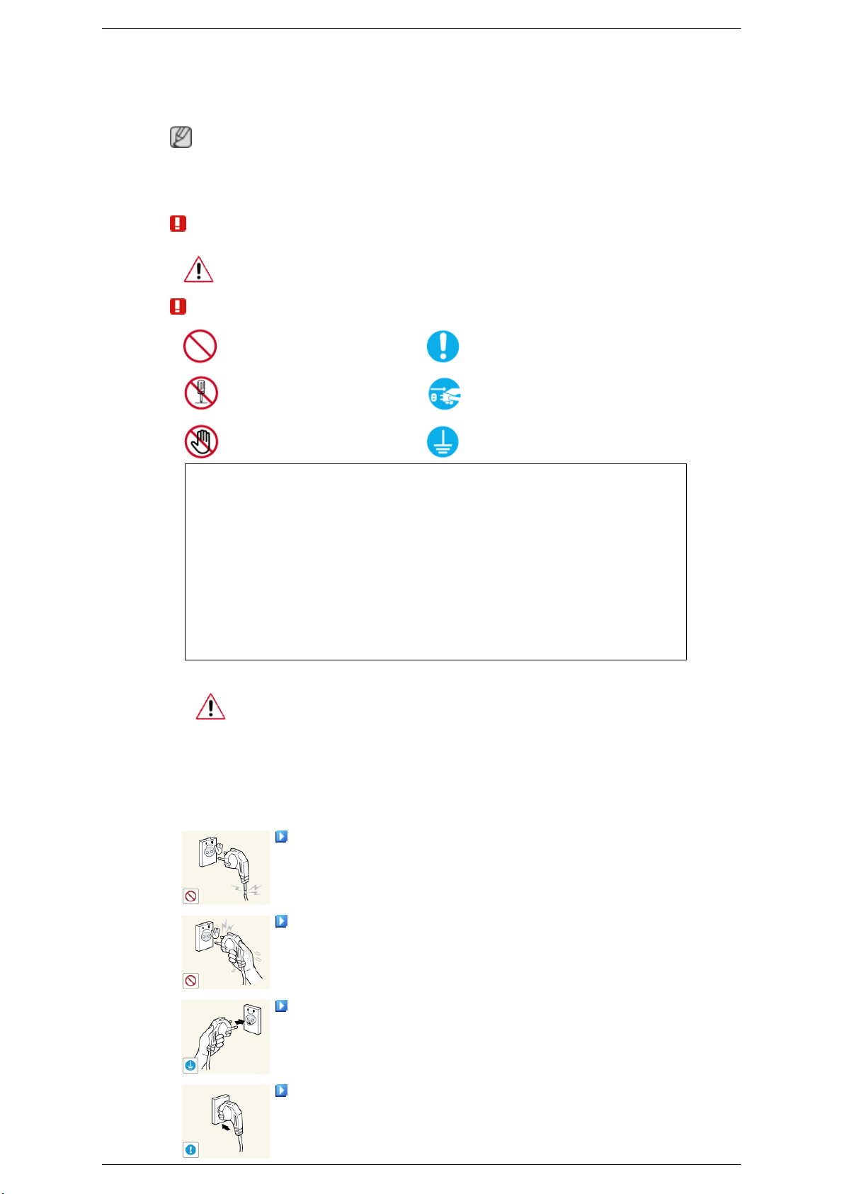
Do not install it in a badly ventilated location such as a bookcase or
closet.
• Otherwise, this may result
temperature.
When putting the product down, make sure to put it down softly.
• Otherwise, this may result in damage to the screen display.
Do not place the front of the product on the floor.
• Otherwise, this may result in damage to the screen display.
Ensure that an authorized installation company installs the wall mount.
• Otherwise, it may fall and cause personal injury.
• Make sure to install the specified wall mount.
Install your product in a well ventilated location. Ensure that there is
a clearance of more than 4 inches (10 cm) from the wall.
• Otherwise, it may result in fire due to an increase in the internal tem-
perature.
Ensure that the packaging vinyl is kept away from children.
in fire due to an increase in the internal
Clean
• Otherwise, it may result in serious harm (suffocation) if children play
with it.
If the height of your monitor is adjustable, do not place any object or
part of your body on the stand when lowering it.
• This may cause damage to the product or the person carrying it.
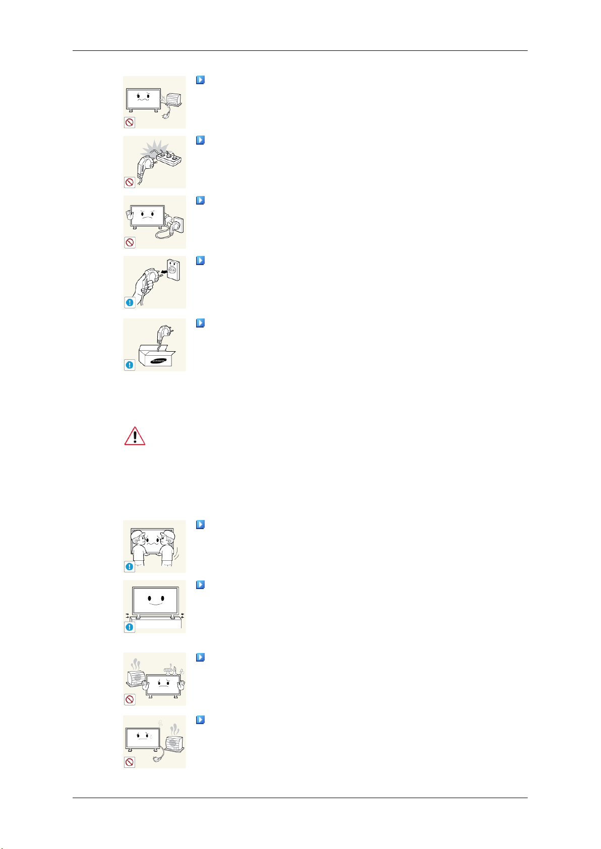
When cleaning the PDP Display case or the surface of the TFT-PDP screen, wipe
with a slightly moistened, soft fabric..
Do not spray cleaner directly onto the surface of the product.
• Otherwise, this may result
structure and the screen surface may peel off.
When cleaning the power plug pins or dusting the power outlet, clean
it with a dry cloth.
• Otherwise, it may result in fire.
in the discoloration and distortion of the
When cleaning the product, make sure to disconnect the power cord.
Otherwise, it may result in electric shock or fire.
•
Safety Instructions
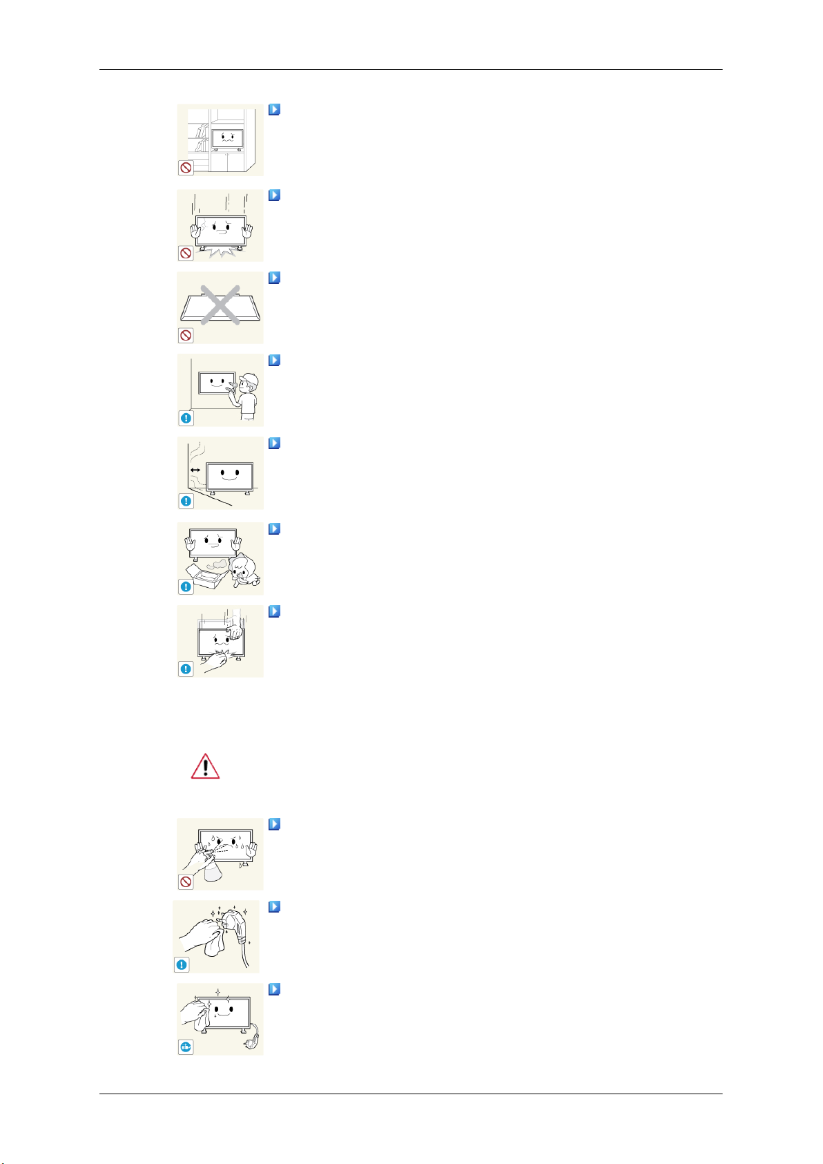
When cleaning the product, disconnect the power cord and clean it with
a soft, dry cloth.
Others
• Do not use chemicals
quito repellant, lubricant, or cleaner.
• These may change the appearance of the product surface and peel off
the indication labels on the product.
Since the product housing is easily scratched, make sure to use the
specified cloth only.
When cleaning the product, do not spray water directly onto the main
body of the product.
• Ensure that water does not enter the product and that it is not wet.
• Otherwise, this may result in electric shock, fire or a malfunction.
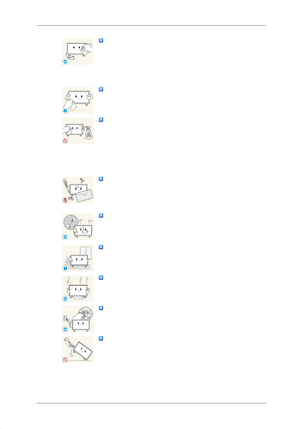
The product is a high voltage product. Do not disassemble, repair or
modify the product yourself.
• Otherwise, this may result in electric shock or fire.
such as wax, benzene, alcohol, thinner, mos-
• If the product needs to be repaired, contact a Service Center.
If there is a strange smell or a strange sound or smoke is coming from
the product, disconnect the
Center.
• Otherwise, this may result in electric shock or fire.
Do not place this product in a location exposed to moisture, dust,
smoke, water, or in a car.
• Otherwise, this may result in electric shock or fire.
When you drop the product or the case is broken, turn the power off
and disconnect the power cord. Contact a Service Center.
• Otherwise, this may result in electric shock or fire.
If thunder or lightning is occurring, do not touch the power cord or
antenna cable.
• Otherwise, this may result in electric shock or fire.
Do not try to move the monitor by pulling only the wire or the signal
cable.
power plug immediately and contact a Service
• Otherwise, it may fall
product or fire due to damage to the cable.
and result in electric shock, damage to the
Safety Instructions
Do not lift or move the product back and forwards or right and left
while only holding the power cord or signal cables.
• Otherwise, it may fall
product or fire due to damage to the cable.
Make sure that the ventilating opening is not blocked by a table or
curtain.
• Otherwise, it may result
perature.
Do not place any containers containing water, vases, flowerpots, medicines as well as any metal on the product.
• If water or a
cord and contact a Service Center.
• This may result in a product malfunction, electric shock, or fire.
Do not use or keep combustible spray or flammable material near the
product.
• Otherwise, this may result in an explosion or fire.
Do not insert any metal, such as chopsticks, coins, pins and steel, or
flammable objects, such as
the ventilating openings, input and output terminals, etc).
• If water or foreign material enters the product, disconnect the power
cord and contact a Service Center.
foreign material enters the product, disconnect the power
and result in electric shock, damage to the
in fire due to an increase in the internal tem-
matches or paper, inside the product (through
• Otherwise, this may result in electric shock or fire.
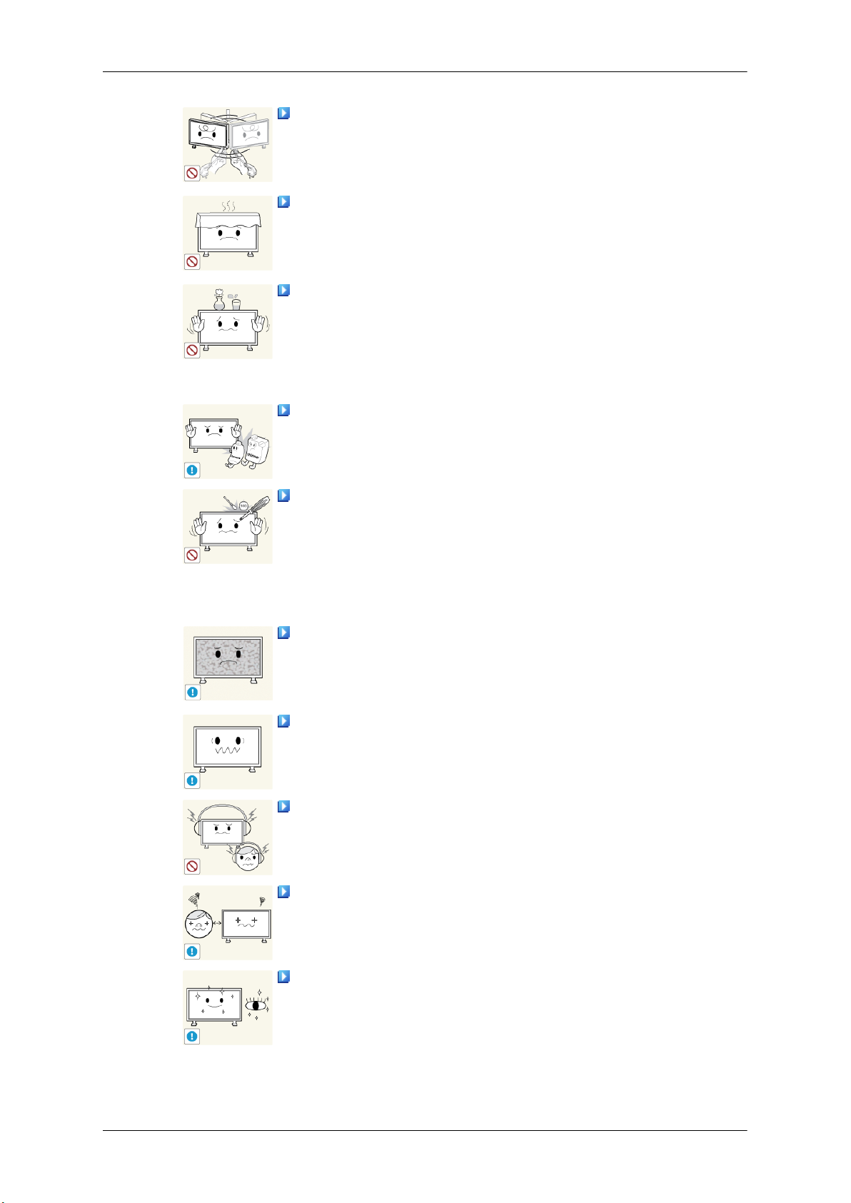
When using a fixed screen for a long time, an afterimage or stain may
occur.
• If you are not
sleep mode or use a moving screen saver.
Set a resolution and frequency appropriate to the product.
• Otherwise, your eyesight may be damaged.
When using headphones or earphones, do not turn the volume too high.
• Having the sound too loud may damage your hearing.
To avoid eyestrain, do not sit too close to the product.
Take a rest for at least five (5) minutes after using the monitor for one
(1) hour.
using your product for a long period of time, put it into
• This reduces eye fatigue.
Safety Instructions
Do not install it in an unstable location such as an unstable rack or
uneven surface or a location exposed to vibrations.
• Otherwise, it may fall
product.
• If you use the product in a location exposed to vibrations, it may
damage the product and result in fire.
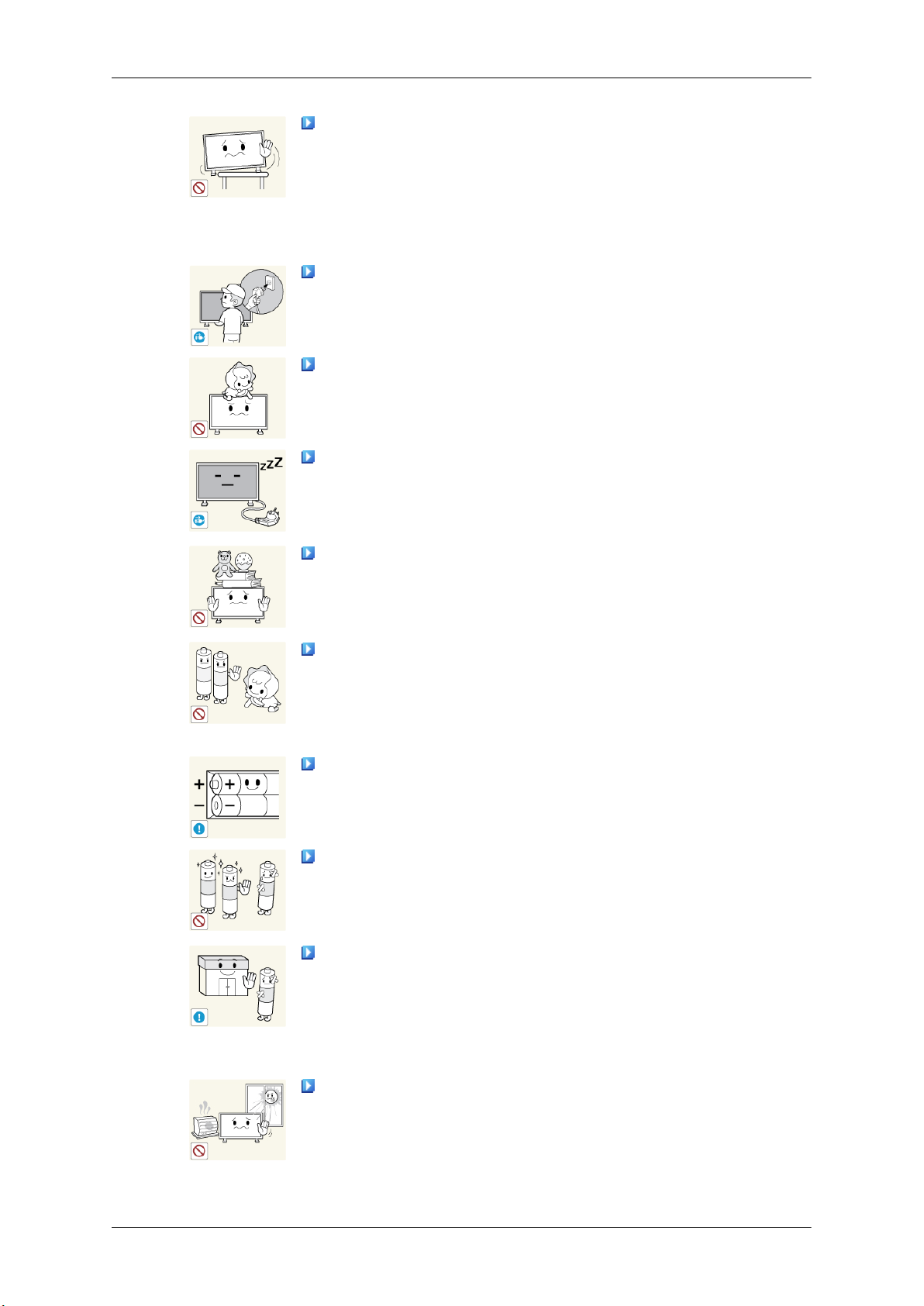
When moving the product, turn the power off and disconnect the power
plug, antenna cable, and all the cables connected to the product.
• Otherwise, it may result in electric shock or fire.
Ensure that children do not hang onto the product or climb up onto the
product.
• The product may fall and cause personal injury or death.
If you do not use the product for a long period of time, disconnect the
power cord from the power outlet.
• Otherwise, this may result in overheating or fire due to dust, and may
result in fire due to electric shock or leakage.
Do not place any heavy items or toys or confectionery, such as cookies
etc. that may attract the attention of children and to the product.
• Your children may hang onto the product causing it to fall and this
may result in personal injury or death.
Be careful that children do not place the battery in their mouths when
removed from the remote control. Place the battery in a location that
children or infants cannot reach.
and cause personal injury and/or damage the
• If children have had the battery in their mouths, consult your doctor
immediately.
When replacing the battery, insert it with the right polarity (+, -).
• Otherwise, the battery may become damaged or it may cause fire,
personal injury or damage due to leakage of the internal liquid.
Use only the specified standardized batteries, and do not use a new
battery and a used battery at the same time.
• Otherwise, the batteries may
jury or damage due to a leakage of the internal liquid.
The batteries (and rechargeable batteries) are not ordinary refuse and
must be returned for
returning the used or rechargeable batteries for recycling.
• The customer can return used or rechargeable batteries to a nearby
public recycling center or to a store selling the same type of the battery
or rechargeable battery.
Do not place the product in a location exposed to direct sunlight or
near any heat such as a fire or heater.
• This may reduce the lifetime of the product, and may result in fire.
recycling purposes. The customer is responsible for
be damaged or cause fire, personal in-
Safety Instructions
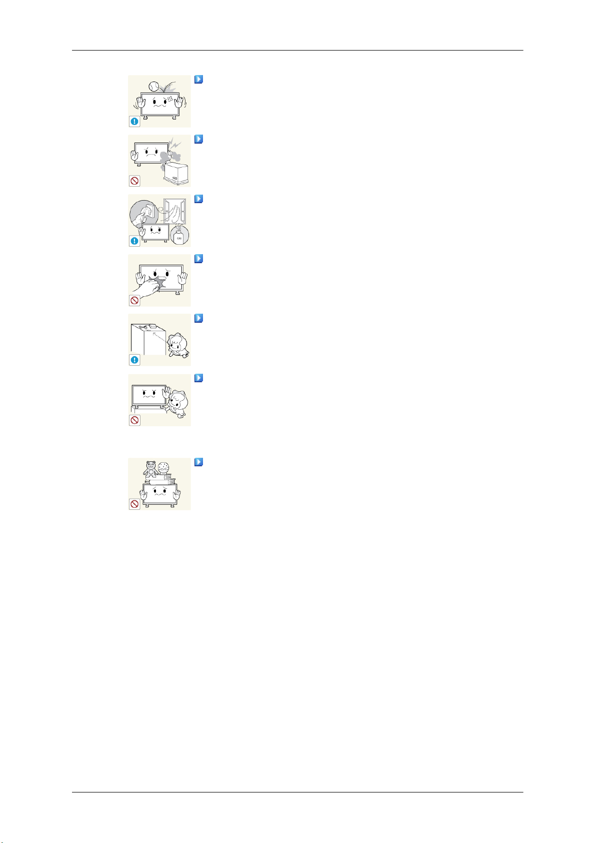
Do not drop any objects onto the product or cause any impact to the
product.
• Otherwise, this may result in electric shock or fire.
Do not use a humidifier near the product.
• Otherwise, this may result in electric shock or fire.
When there is a gas leak, do not touch the product or the power plug;
ventilate immediately.
• If a spark occurs, it may cause an explosion or fire.
If the product has been turned on for a long time, the display panel
becomes hot. Do not touch it.
Keep the small accessories in a location out of the reach of children.
Do not install the product in a location low enough for children to
reach.
• Otherwise, it may fall and result in personal injury.
• Since the
level and stable surface.
Do not put any heavy objects on the product.
• This may result in personal injury and/or damage to the product.
front part of the product is heavy, install the product on a
Introduction
Package Contents
Note
Please make sure the following items are included with your PDP Display.
If any items are missing, contact your dealer.
Contact a local dealer to buy optional items.
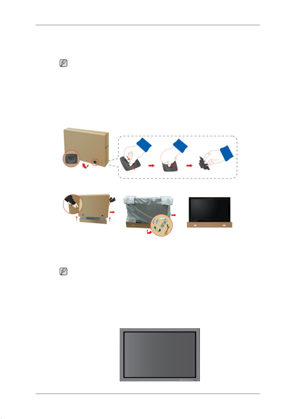
Checking the Contents of the Package
Remove the lock from the package box, as shown in the figure above.
holding the grooves on both
• After unpacking the package, make sure to check the contents of the package.
• Make sure to keep the package box for transporting the product in the future.
• After
Unpacking
Lift up the package box by
sides of the package box.
Note
unpacking, you may use the lower part of the package box as a temporary stand for product
test or operation check.
Check the contents of the
package.
Remove the Styrofoam and
vinyl cover.
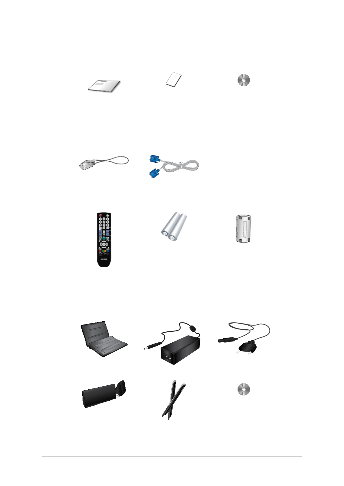
Manuals
Introduction
PDP Display
Quick Setup Guide Warranty Card
(Not available in all loca-
Cables
Power Cord D-Sub Cable
Others
Remote Control Batteries (AAA X 2)
User's Guide
tions)
Ferrite Core for Power Cord
(Not available in all loca-
tions)
Options (P64FT Model Only)
Pen battery charger(IWB-C1) Adapter Power Cord
USB Dongle(IWB-D1) Zigbee Touch Pen(IWB-P1) Samsung Interactive white-
board

Introduction
Pen battery charger(IWB-C1), USB Dongle(IWB-D1), Zigbee Touch Pen(IWB-P1) only in P64FT model
NOTE: This equipment has been tested and found to comply with the limits for a Class B digital device,
pursuant to part 15 of the FCC Rules. These limits are designed to provide reasonable protection against
harmful interference in a residential installation. This equipment generates, uses and can radiate radio
frequency energy and, if not installed and used in accordance with the instructions, may cause harmful
interference to radio communications. However, there is no guarantee that interference will not occur in a
particular installation. If this equipment does cause harmful interference to radio or television reception,
which can be determined by turning the equipment off and on, the user is encouraged to try to correct the
interference by one or more of the following measures:
—Reorient or relocate the receiving antenna.
—Increase the separation between the equipment and receiver.
—Connect the equipment into an outlet on a circuit different from that to which the re-ceiver is connected.
—Consult the dealer or an experienced radio/ TV technician for help.
Warning : This equipment may generate or use radio frequency energy. Changes or modifications to this
equipment may cause harmful interference unless the modifications are expressly approved in the instruction
manual. The user could lose the authority to operate this equipment if an unauthorized change or modification
is made.
This device complies with Part 15 of the FCC's Rules. Operation is subject to the following two Conditions :
1. This device may not cause harmful interference. and
2. This device must accept ant interference received, including interference that may cause undesirable operation.
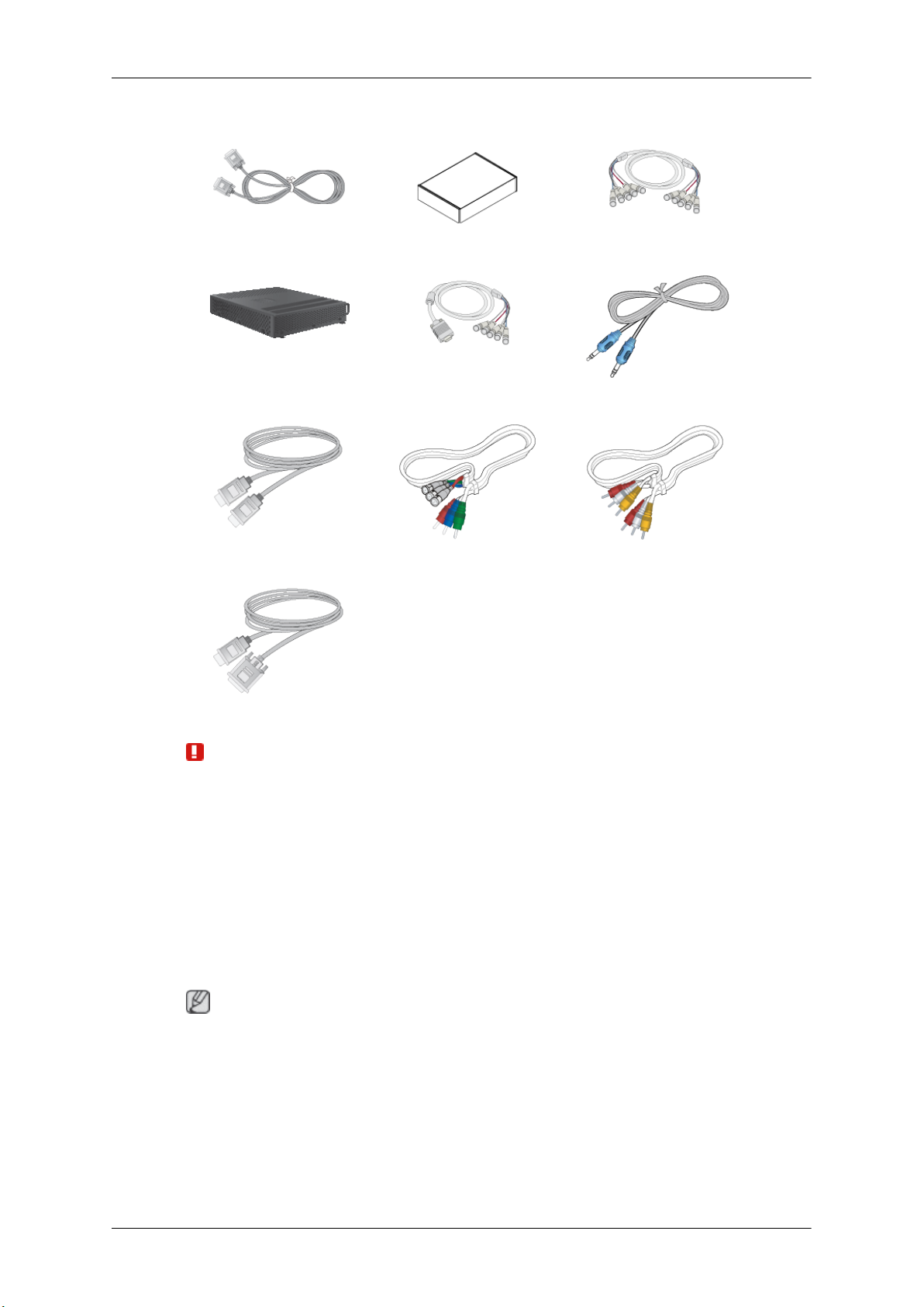
Sold separately
DVI Cable Wall Mount KIT BNC to BNC Cable
Network Box RGB to BNC Cable STEREO Cable
Introduction
HDMI Cable BNC-COMPONENT Cable COMPOSIT Cable
HDMI-DVI Cable
Warning
• The network box is not compatible with the Interactive Whiteboard program.
Your PDP Display
Note
The PDP device may interfere with an amateur radio or AM radio.
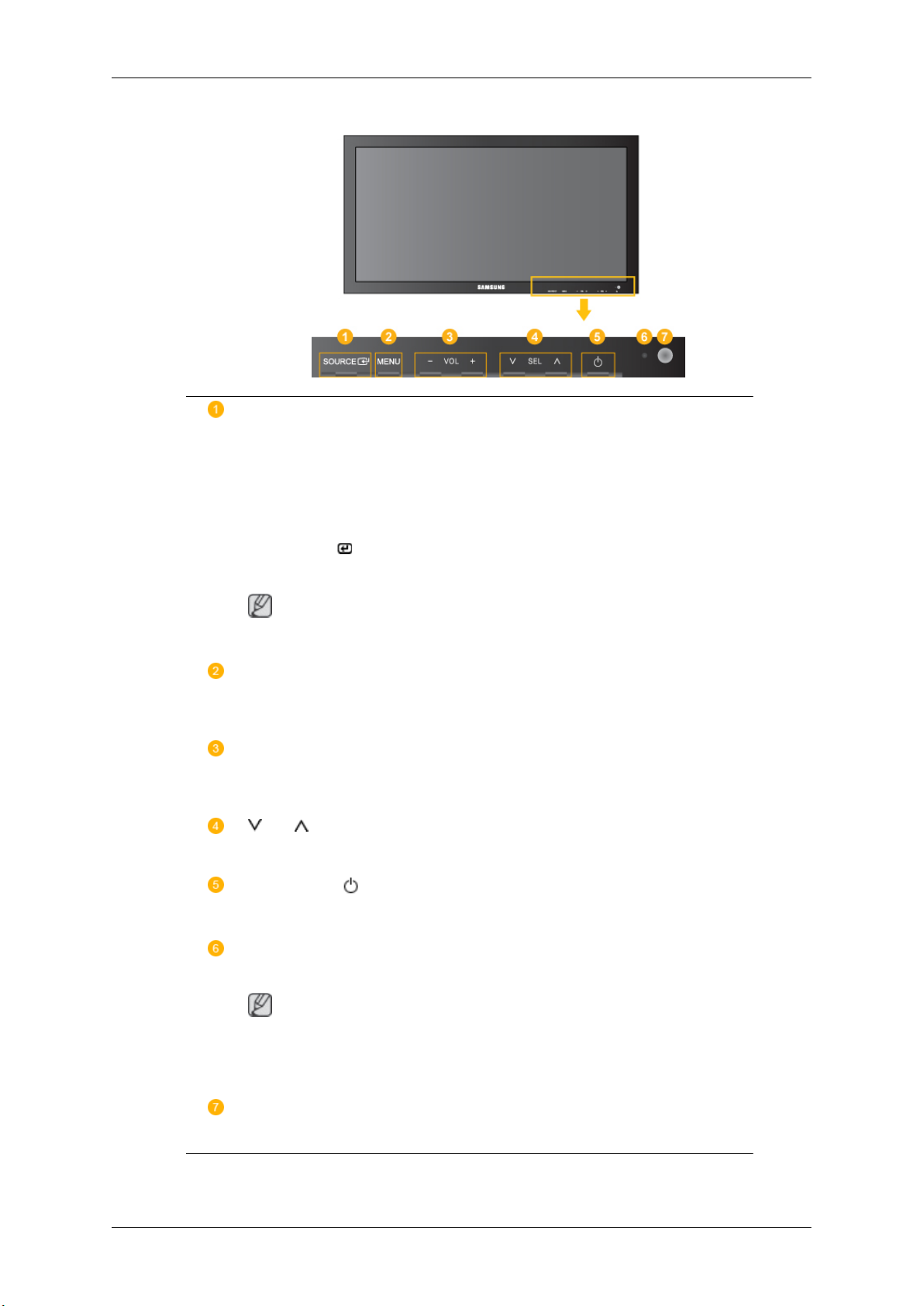
Front
Introduction
SOURCE button [SOURCE]
Switches from PC mode
external devices that are connected to the PDP Display at the time.
[PC] → [DVI] → [AV] → [HDMI] → [MagicInfo] → [Component] →
[BNC]
Enter button [
Activates a highlighted menu item.
Note
• This product is not compatible with MagicInfo.
MENU button [MENU]
Opens the on-screen menu
or return to the previous menu.
- VOL+
Moves from one menu item to another horizontally or adjusts selected menu values. When OSD is not on the screen, push the button to adjust volume.
SEL
Moves from one menu item to another vertically or adjusts selected menu values.
Power button [ ]
]
to Video mode. Changing the source is only allowed for
and exits from the menu. Also use to exit the OSD menu
Use this button for turning the PDP Display on and off.
Power indicator
Shows PowerSaver mode by blinking green
Note
See PowerSaver described in the manual for further information regarding power
saving functions. For energy conservation, turn your PDP Display OFF when it is
not needed or when leaving it unattended for long periods.
Remote Control Sensor
Aim the remote control towards this spot on the PDP Display.
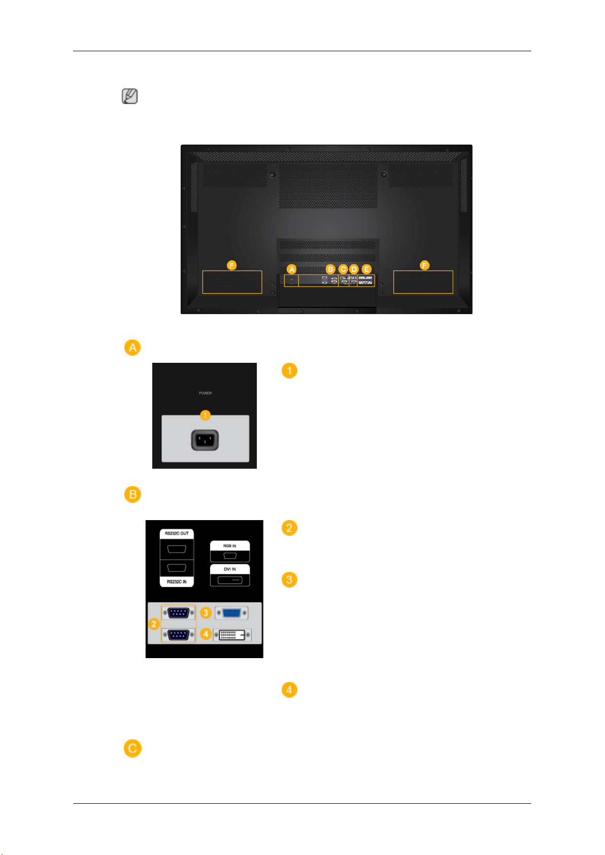
Rear
Introduction
Note
For detailed information concerning
PDP Display's configuration at the back may vary slightly depending on the PDP Display model.
cable connections, refer to Connecting Cables under Setup. The
POWER IN
The power cord plugs
the wall plug.
into the PDP Display and
RS232C OUT/IN (RS232C Serial PORT)
MDC(Multiple Display Control) Program Port
RGB IN (PC Connection Terminal (Input))
• Use a D-Sub Cable
(Analog PC)
• Connect the RGB IN port on the monitor to
the BNC port on the PC using the RGB to
BNC cable.
DVI IN (PC Video Connection Terminal)
Connect the [DVI IN]
DVI port on the PC using the DVI cable.
(15 pin D-Sub) - PC mode
port on the monitor to the
Introduction
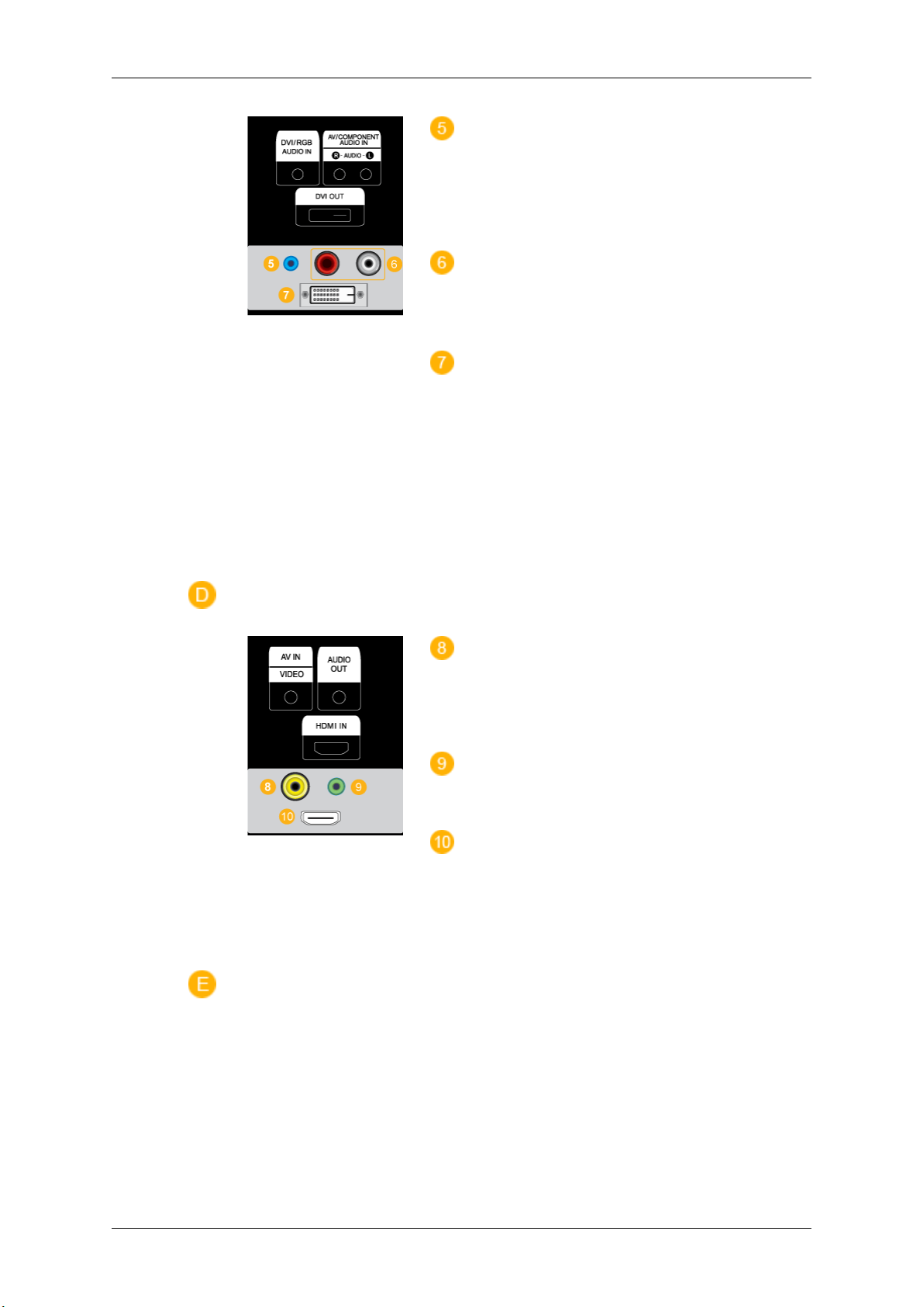
DVI/RGB AUDIO IN(PC/DVI Audio Con-
nection Terminal (Input))
Connect an audio cable
monitor and the audio out port on the source device.
AV/COMPONENT AUDIO IN [R-AUDIO-L]
Connect an audio cable
monitor and the audio out port on the source device.
DVI OUT
• Connect a monitor to
a DVI cable.
• Connect the [DVI OUT] port on the monitor
to the [HDMI IN] port on the other monitor
using the DVI to HDMI cable.
• DVI, HDMI and network signals sent via the
[DVI OUT] port are displayed on the second
display which has the DVI IN port.
to [R-AUDIO-L] on the
to [R-AUDIO-L] on the
another monitor through
AV IN [VIDEO]
Connect the [AV IN
monitor to the video output terminal of the external device using a VIDEO cable.
AUDIO OUT
Headphone/External speaker output terminal.
HDMI IN
Connect the HDMI terminal
PDP Display to the HDMI terminal of your digital
output device using a HDMI cable.
Up to HDMI cable 1.2 can be supported.
(VIDEO)] terminal of your
at the back of your
Introduction
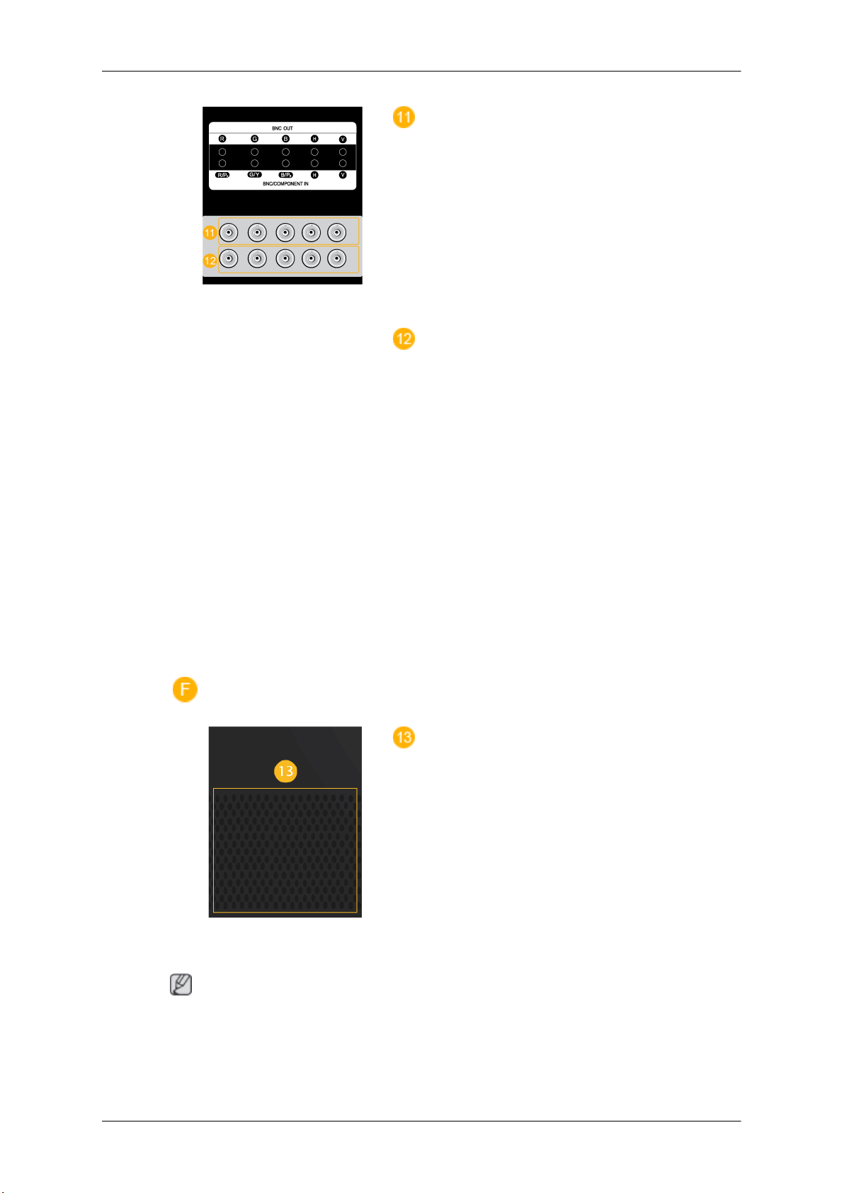
BNC OUT [R, G, B, H, V] (BNC Terminal
(Output))
BNC (Analog PC) Connection:
G, B, H, V ports.
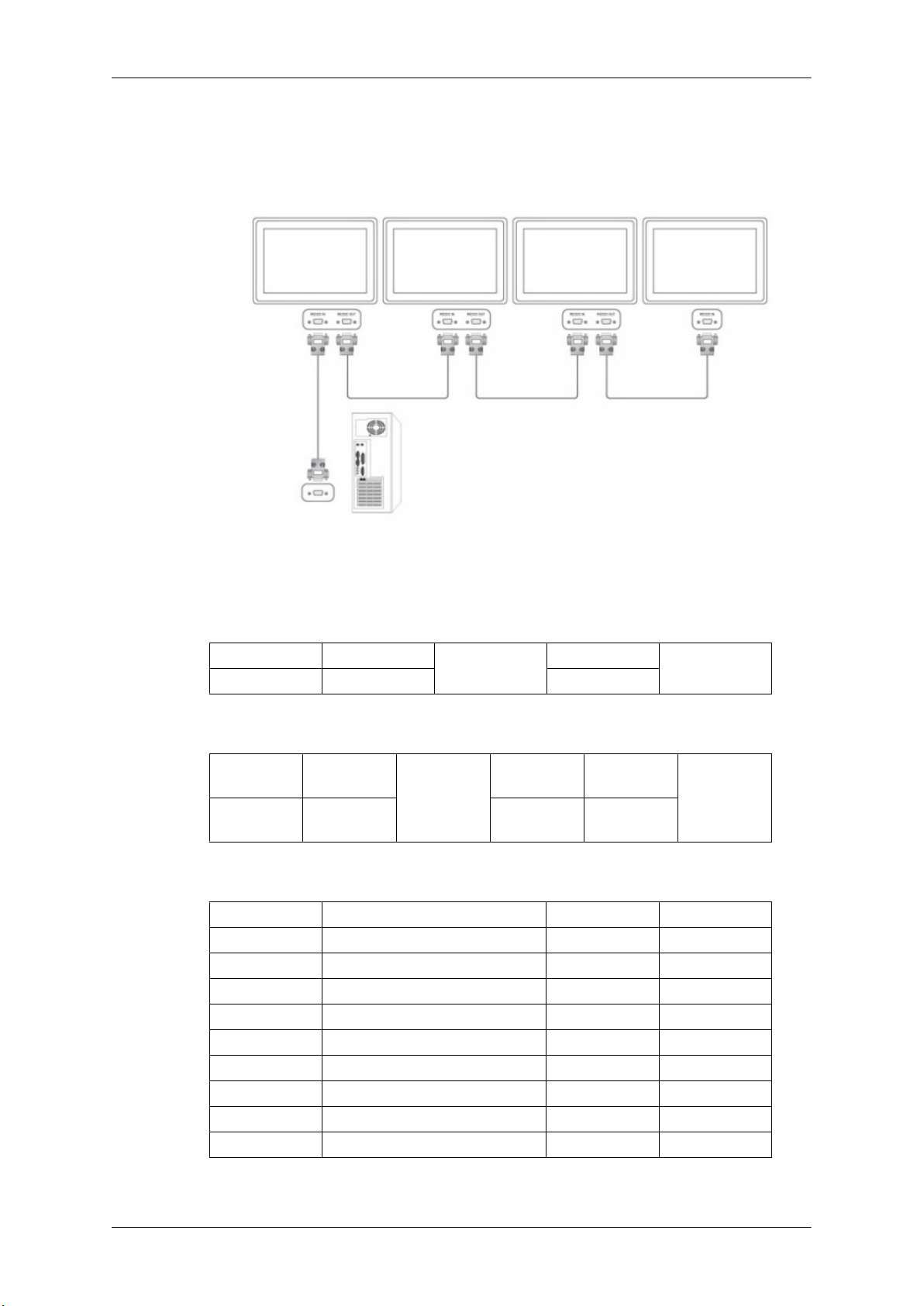
The number of PDP Displays that can be connected to the loopout depends on the cables, signal
source, etc. With cables or signal source where
there is no degradation, up to 10 PDP Displays
can be connected (May not be supported depending on the connected cable).
BNC/COMPONENT IN [R/PR, G/Y,
V] (BNC/Component Connection Terminal (input))
- During BNC input, please check specifications
for the input ports below.
• [R/PR] --> Red port input
• [G/Y] --> Green port input
• [B/PB] --> Blue port input
- During component input, please check specifi-
cations for the input ports below.
connecting the R,
B/PB, H,
Remote Control
Note
• [R/Y] --> Green port input
• [G/PB] --> Blue port input
• [B/PR] --> Red port input
This product has an internal speaker.
The performance of the
near the PDP Display , causing a malfunction due to interference with the frequency.
remote control may be affected by a TV or other electronic device operating
Introduction
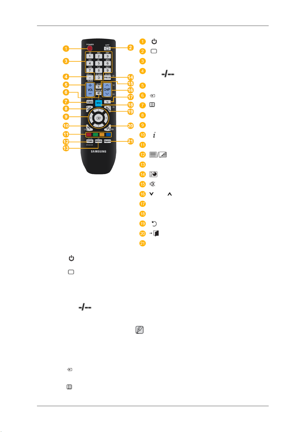
POWER
OFF
Number Buttons
DEL / GUIDE button
- VOL +
SOURCE
D.MENU
TOOLS
Up-Down Left-Right buttons
INFO
COLOR BUTTONS
TTX/MIX
MTS/DUAL
ENTER/PRE-CH
MUTE
CH/P
TV
MENU
RETURN
EXIT
MagicInfo
1. POWER
2. OFF
3. Number Buttons Used to enter the
4. DEL
/ GUIDE button
Turns the product On.
Turns the product Off.
MagicInfo.
The "-" button is used to select Digital channels.
Electronic Program Guide (EPG) display.
password during the OSD adjustment or to use
Note
- This button is disabled for this PDP display.
5. - VOL + Adjusts the audio volume.
6. SOURCE
7.
D.MENU DTV menu display
Press this button to
nected external input source.
switch to MagicInfo or PC mode or a con-
Introduction
Note
- This button is disabled for this PDP display.
8. TOOLS
Up-Down Left-Right buttons
9.
10.
11. COLOR BUTTONS Press to add or delete channels and to store channels to the favorite
12.
INFO
TTX/MIX
Use to quickly select frequently used functions.
Note
- This button is disabled for this PDP display.
Moves from one menu item to another horizontally, vertically or
adjusts selected menu values.
Current picture information is
of the screen.
channel list in the “Channel List” menu.
Note
- This button is disabled for this PDP display.
TV channels provide written information services via teletext.
- Teletext Buttons
displayed on the upper left corner
13. MTS/DUAL
Note
- This button is disabled for this PDP display.
Note
- This button is disabled for this PDP display.
MTS-
You can select MTS (Multichannel Television Stereo) mode.
Audio Type MTS/S_Mode Default
FM Stereo Mono Mono Manual Change
Stereo
SAP
DUAL-
STEREO/MONO,
MONO/NICAM STEREO can be operated depending on the
broadcasting type by using the DUAL button on the remote control
while watching TV.
DUAL l /
Mono ↔ Stereo
Mono ↔ SAP
DUAL ll and MONO/NICAM
Mono
14.
ENTER/PRE-CH
This button is used
to return to the immediately previous channel.
Introduction
Note
- This button is disabled for this PDP display.
15. MUTE
CH/P In TV mode, selects TV channels.
16.
17. TV Selects the TV mode directly.
18. MENU Opens the on-screen menu
19.
20. EXIT
21. MagicInfo MagicInfo Quick Launch Button.
RETURN
Pauses (mutes) the audio
the lower left corner of the screen. The audio comes back on if
MUTE or - VOL + is pressed in the Mute mode.
Note
- This button is disabled for this PDP display.
Note
- This button is disabled for this PDP display.
adjustment menu.
Returns to the previous menu.
Exits from the menu screen.
output temporarily. This is displayed on
and exits from the menu or closes the
User Installation Guide
Note
• Be sure to call an installation expert of Samsung Electronics to install the product.
• The warranty
authorized by Samsung Electronics.
• A Samsung Electronics service center can provide details.
becomes invalid if the product is installed by someone other than a professional
Note
This button is disabled
fo.
for products that do not support MagicIn-
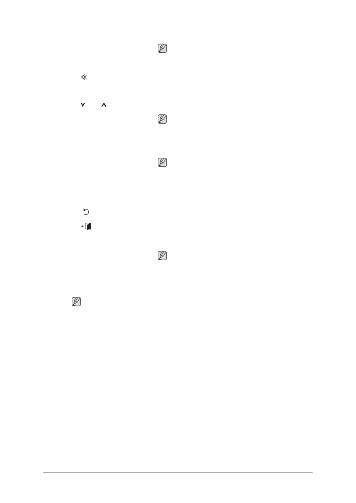
Tilt Angle and Rotation
1 2
1. The product can be tilted up to 15 degrees from a vertical wall.
Introduction
2. To use the product in portrait mode, rotate it clockwise so that the LED indicator is at the bottom.
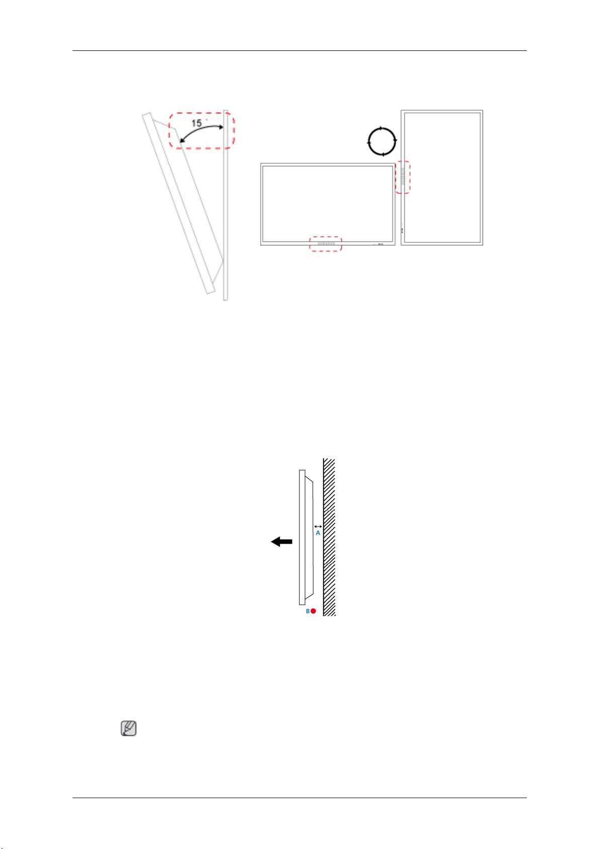
Ventilation requirement
1. Vertical wall mount condition
<Side view>
A : min. 40 mm
B: Ambient temperature Measuring point < 35°C
• When installing the product onto a vertical wall, be sure there is a 40 mm space or more behind
the product for
Note
A Samsung Electronics service center can provide details.
ventilation, as shown above, and maintain the ambient temperature at 35°C or lower.
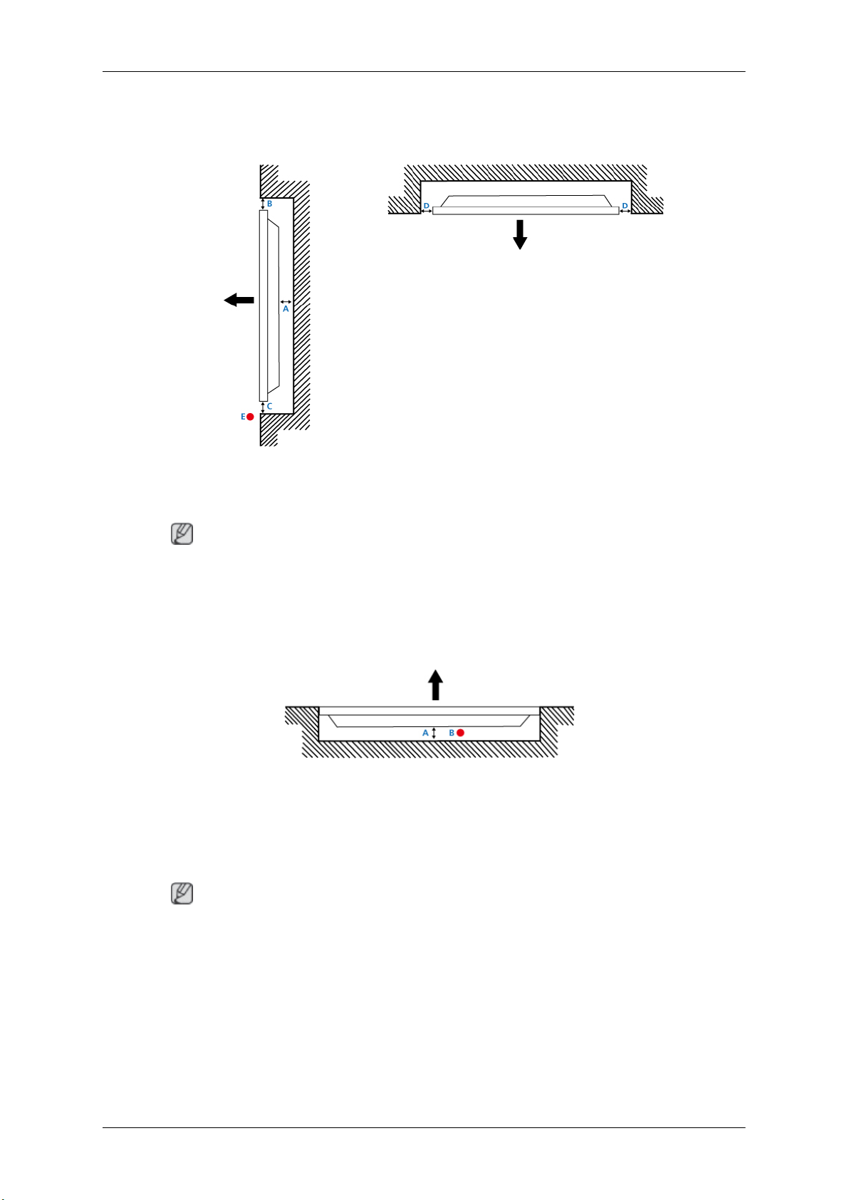
2. Embedded Mount guide
<Side view> <Top view>
Introduction
A : min. 40 mm
B : min. 70 mm
C : min. 50 mm
D : min. 50 mm
E : Ambient temperature Measuring point < 35°C
• When embedding the product in a wall, be sure there is some space behind the product for ventilation, as shown above, and maintain the ambient temperature at 35°C or lower.
Note
A Samsung Electronics service center can provide details.
3. Floor mount guide
<Side view>
A: min. 50 mm
B: Ambient temperature Measuring point < 20°C
• When embedding the product in the floor, be sure there is a 50 mm space or more behind the product
for ventilation, as shown above, and maintain the ambient temperature at 20 °C or lower.
Note
A Samsung Electronics service center can provide details.
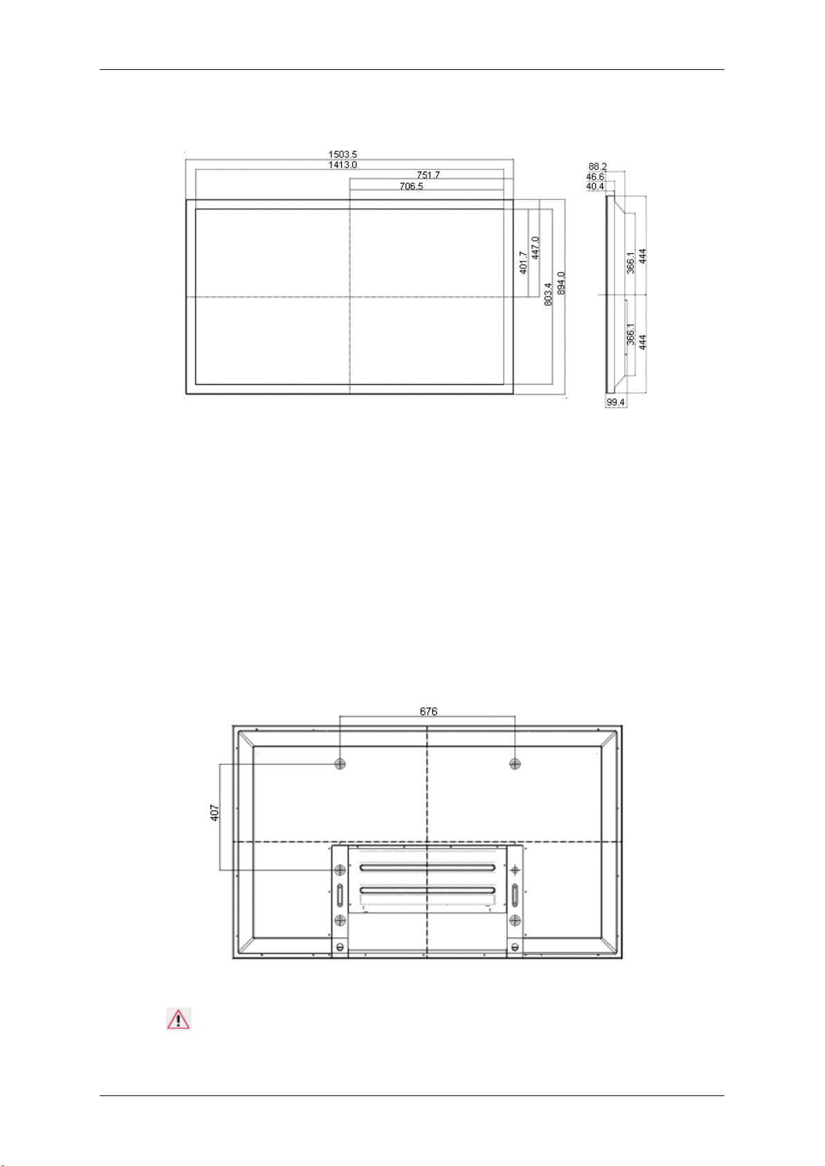
Mechanical Layout
* Unit: mm
Introduction
Installation VESA Bracket
• When installing VESA, make sure to comply with the international VESA standards.
• Purchasing VESA
Distributor to place an order. After your order is placed, installation professionals will visit you
and install the bracket.
• At least 2 persons are needed in order to move the PDP Display.
• SAMSUNG is not responsible for any product damage or any injury caused by installation at
customer's discretion.
Bracket and Installation Information : Please contact your nearest SAMSUNG
Dimensions
* Unit: mm
Notice
For securing the bracket
on a wall, use only machine screws of 6 mm diameter and 8 to 12 mm length.
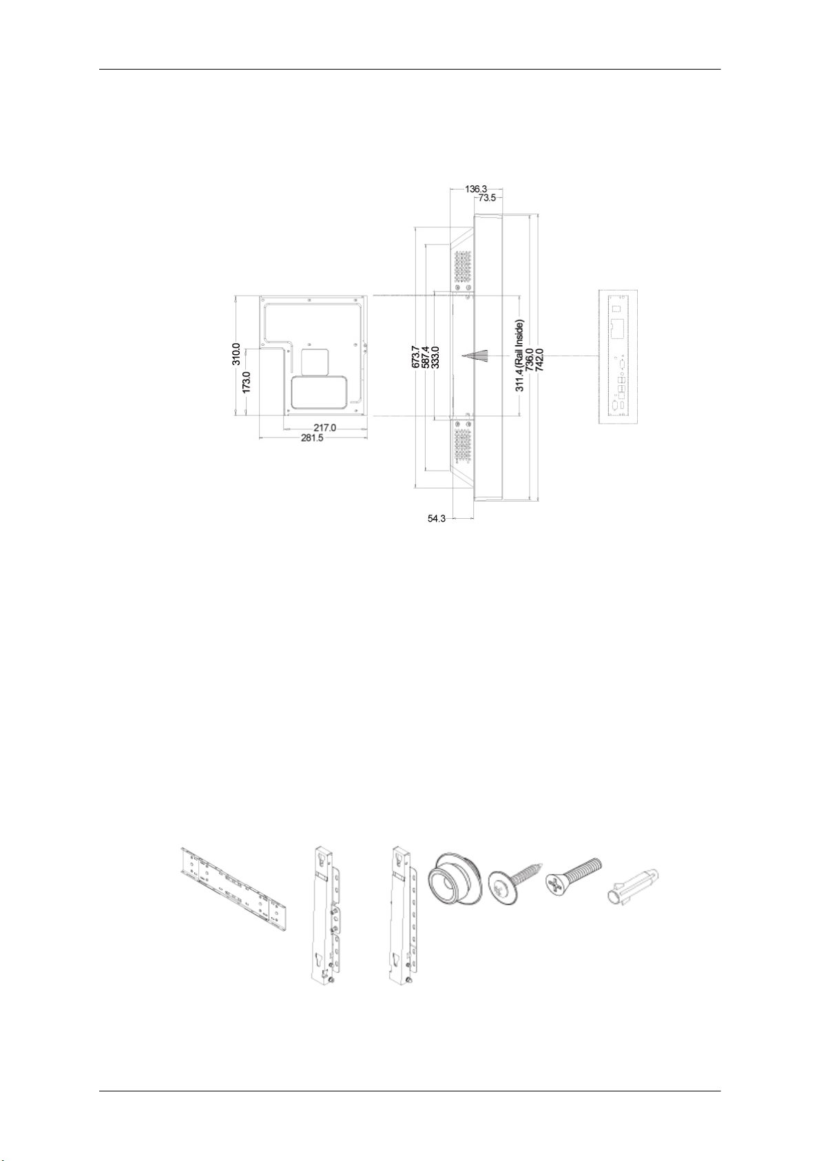
Accessories (sold separately)
• Dimension with other accessories
Introduction
* Unit: mm
Wall Bracket Installation
•
Contact a technician for installing the wall bracket.
• SAMSUNG Electronics
when the installation is done by the customer.
• This product is for installing on cement walls. The product may not stay in place when installed
on plaster or wood.
Components
Only use the components and accessories shipped with the product.
is not responsible for any damages to the product or harm to customers
Wall Bracket(1) Hinge(Left 1, Right1)Plastic
Hanger
(4)
Screw
(A)(11)
Screw(B)
(4)
Anchor
(11)
Introduction
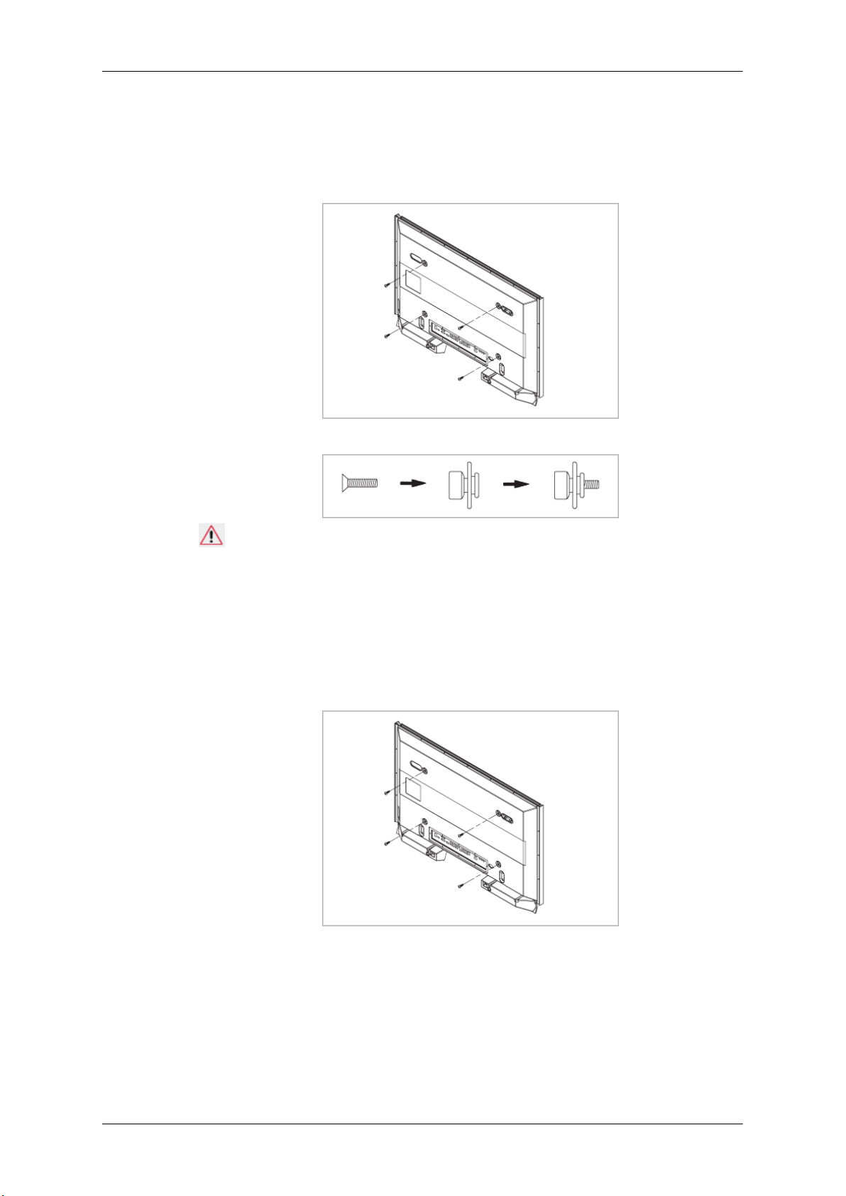
To mount the product on the wall bracket
The shape of the
the screw are the same)
1. Remove the 4 screws on the back of the product.
2. Insert the screw B into the plastic hanger.
product may vary depending on the model. (The assemblies of the plastic hanger and
Notice
• Mount the product on
plastic hangers.
• Be careful when installing the product on the bracket as fingers can be caught in the holes.
• Make sure the wall bracket is securely fixed to the wall, or the product may not stay in place
after installation.
3. Tighten the 4 screws in step 2 (plastic hanger + screw B) to the rear holes of the product.
4. Remove safety pin (3)
Then place the product(2) so that it is firmly fixed to the bracket. Make sure to re-insert and tighten
the safety pin (3) to securely hold the product to the bracket.
the wall bracket and make sure it is properly fixed to the left and right
and insert the 4 product holders into the corresponding bracket holes (1).
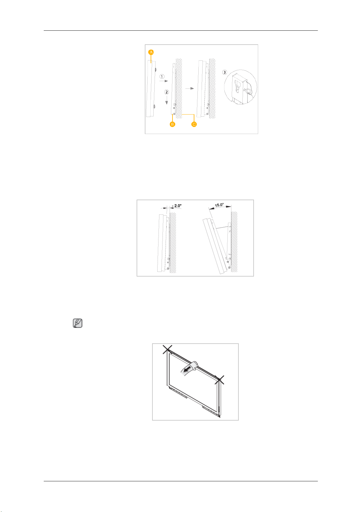
A - PDP Display
B - Wall Bracket
C - Wall
Wall Bracket Angle Adjustment
Adjust the bracket angle to -2° before installing it on the wall.
Introduction
1. Fix the product to the wall bracket.
2. Hold the product at
angle.
Note
You can adjust the bracket angle between -2° and 15°.
Make sure to use the top center, and not the left or the right side of the product to adjust the angle.
the top in the center and pull it forward (direction of the arrow) to adjust the
Remote Control (RS232C)
Cable connections
interface RS232C(9 pin)
pin TxD(No.2) RxD(No.3) GND(No.5)
Bits rate 9600 bps
Data Bits 8 bit
Parity None
Stop Bits 1 bit
Flow control None
Maximum length 15 m (only shielded type)
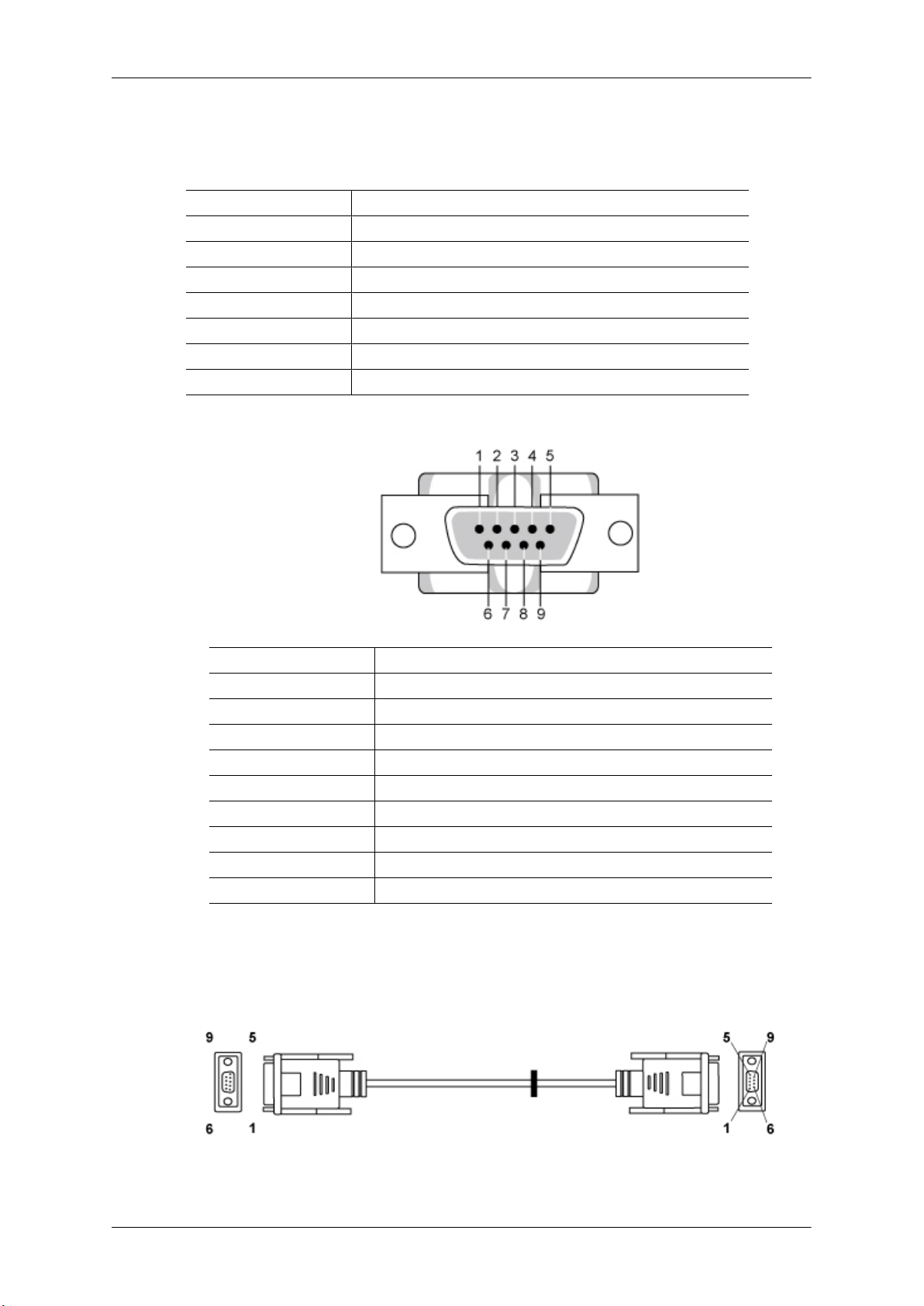
• Pin assignment
Introduction
Pin Signal
1 Data Carrier Detect
2 Received Data
3 Transmitted Data
4 Data Terminal Ready
5 Signal Ground
6 Data Set Ready
7 Request to Send
8 Clear to Send
9 Ring Indicator
• RS232C cable
Connector : 9-pin D-Sub
Cable : Cross (reversed) cable
-P1- -P1- -P2- -P2-
FEMALE Rx 2 ---------> 3 Rx FEMALE
Introduction
• Connecting method
Tx
Gnd
3
5
<---------
----------
2
5
Tx
Gnd
Control codes
• Get control
• Set control
• commanding words
No. command type command Value range
1 Power control 0x11 0~1
2 Volume control 0x12 0~100
3 Input source control 0x14 4 Screen Mode control 0x18 5 Screen Size control 0x19 0~255
6 PIP on/off control 0x3C 0~1
7 Auto adjustment control 0x3D 0
8 Video wall Mode control 0x5C 0~1
9 Safety Lock 0x5D 0~1
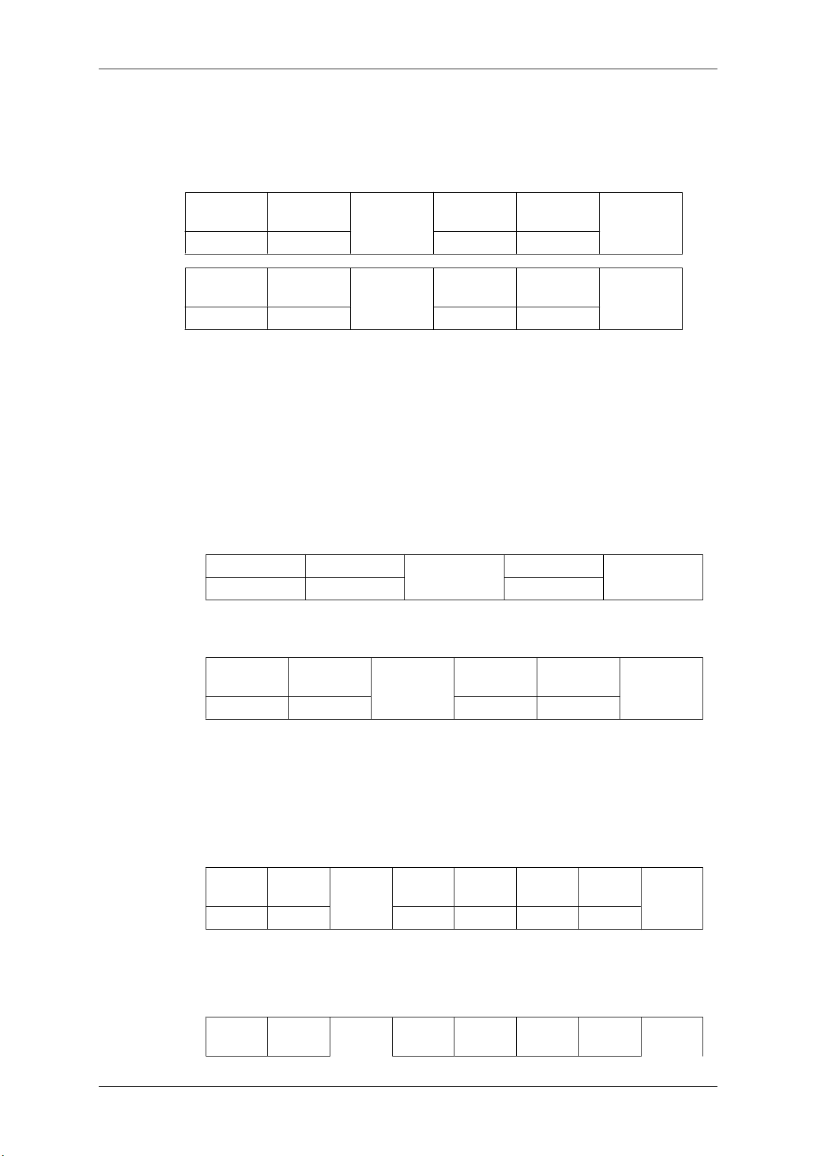
Header
0xAA command type 0
Header command
0xAA command
command
ID
ID
type
DATA Length
DATA
Length
1 Value
CheckSum
DATA
CheckSum
- ID should show hexadecimal value of assigned ID, but ID 0 should be 0xFF.
Introduction
- Every communication will be made in hexadecimals and Checksum is the sum of all remainings.
If it exceeds two digits,for example, it is 11+FF+01+01=112, discard the number in the first digit
like below.
example)PowerOn&ID=0
Header command
ID
0xAA 0x11 1 Power
Header command
ID
0xAA 0x11 1 1
If you want to control every mechanism connected with Serial Cable regardless of its ID, set ID
part to "0xFE" and
not respond with ACK.
• Power Control
• Function
Personal Computer turns TV / Monitor power ON/OFF.
• Get Power ON/OFF Status
Header
0xAA 0x11 0
send commands. At the time, each product will follow commands but it will
command
DATA
Length
DATA
Length
ID
DATA 1
CheckSum
DATA 1
12
DATA Length
CheckSum
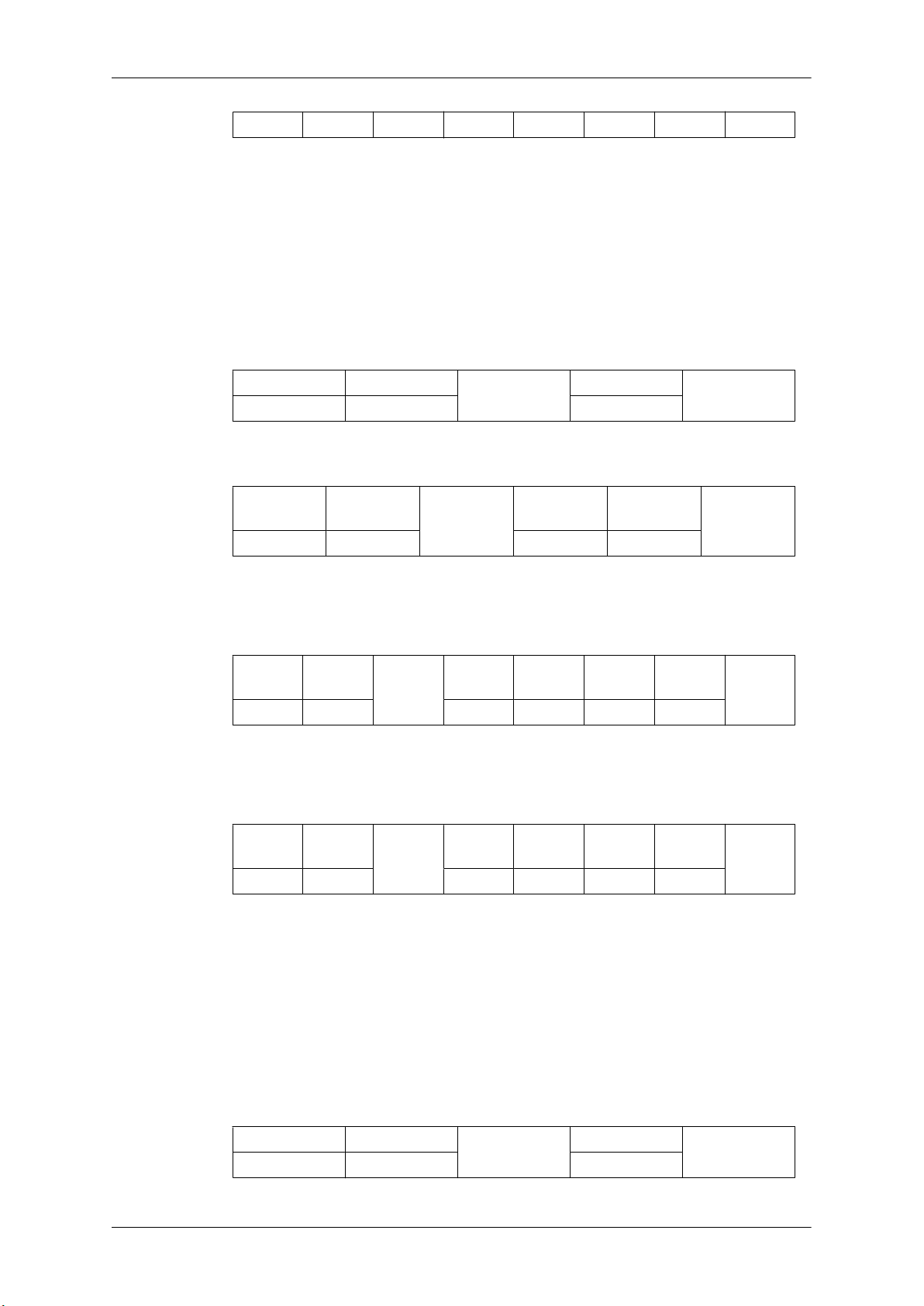
• Set Power ON/OFF
Header command
ID
0xAA 0x11 1 Power
Power : Power code to be set on TV / Monitor
1 : Power ON
0 : Power OFF
•
Ack
Header
0xAA 0xFF 3 ‘A’ 0x11 Power
Power : Same as above
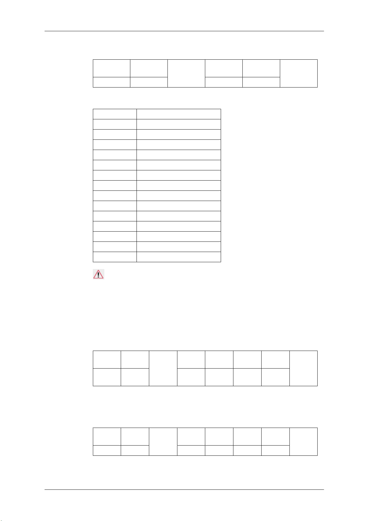
• Nak
Header command
command
ID
ID
DATA
Length
DATA
Length
DATA
Length
Ack/Nak r-CMD Val1
Ack/Nak r-CMD Val1
DATA
CheckSum
Check
Sum
Check
Sum
0xAA 0xFF 3 ‘N’ 0x11 ERR
ERR : Error code that shows what occurred error is
• Volume Control
• Function
Personal Computer changes volume of TV / Monitor.
• Get Volume Status
Introduction
Header
0xAA 0x12 0
• Set Volume
Header command
0xAA 0x12 1 Volume
Volume : Volume value code to be set on TV / Monitor (0 ~ 100)
• Ack
Header command
0xAA 0xFF 3 ‘A’ 0x12 Volume
Volume : Same as above
• Nak
command
ID
ID
DATA
Length
ID
Ack/Nak r-CMD Val1
DATA Length
DATA
Length
CheckSum
DATA
CheckSum
Check
Sum
Header command
0xAA 0xFF 3 ‘N’ 0x12 ERR
ERR : Error code that shows what occurred error is
• Input Source Control
• Function
Personal Computer changes input source of TV / Monitor.
• Get Input Source Status
Header
0xAA 0x14 0
ID
command
DATA
Length
Ack/Nak r-CMD Val1
DATA Length
ID
Check
Sum
CheckSum
• Set Input Source
Introduction
Header
0xAA 0x14 1 Input Source
Input Source : Input Source code to be set on TV / Monitor
0x14 PC
0x1E BNC
0x18 DVI
0x0C AV
0x04 S-Video
0x08 Component
0x20 MagicInfo
0x1F DVI_VIDEO
0x30 RF(TV)
0x40 DTV
0x21 HDMI1
0x22 HDMI1_PC
0x23 HDMI2
0x24 HDMI2_PC
0x25 DisplayPort
command
ID
DATA
Length
DATA
CheckSum
Caution
DVI_VIDEO, HDMI1_PC, HDMI2_PC → Get Only
In the case of MagicInfo, only possible with models include MagicInfo
In the case of TV, only possible with models include TV.
• Ack
Header
0xAA 0xFF 3 ‘A’ 0x14
Input Source : Same as above
• Nak
Header
0xAA 0xFF 3 ‘N’ 0x14 ERR
command
ID
command
ID
DATA
Length
DATA
Length
Ack/Nak r-CMD Val1
Ack/Nak r-CMD Val1
Input
Source
Check
Sum
Check
Sum
ERR : Error code that shows what occurred error is
 Loading...