

Page 1

SyncMaster P64FP P64FT
PDP Display
User Manual
The color and the appearance may differ depending on the
product, and the specifications are subject to change
without prior notice to improve the performance.
Page 2
Safety Instructions
Notational
Note
These safety instructions must be followed to ensure your safety and prevent property damage.
Make sure to read the instructions carefully and use the product in the correct manner.
Warning / Caution
Failure to follow directions noted by this symbol could result in bodily harm
or damage to the equipment.
Note
Power
Prohibited
Do not disassemble
Do not touch
An administration fee may be charged if either
• (a) an engineer is called out at your request and there is no defect in the product
(i.e. where you have failed to read this user manual).
• (b) you bring the unit to a repair centre and there is no defect in the product
(i.e. where you have failed to read this user manual).
The amount of such administration charge will be advised to you before any work or
home visit is carried out.
When not used for extended period of time, set your computer to DPM.
If using a screen saver, set it to active screen mode.
Important to read and understand at all times
Disconnect the plug from the
outlet
Ground to prevent an electric
shock
The images here are for reference only, and are not applicable in all cases (or
countries).
Shortcut to Anti-Afterimage Instructions
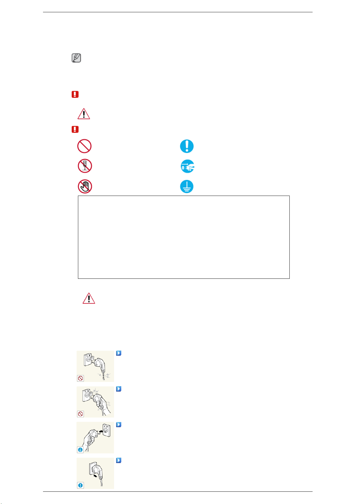
Do not use a damaged power cord or plug or a damaged or loose power
outlet.
• Otherwise, this may result in electric shock or fire.
Do not touch the power plug with wet hands when removing or plug-
ging the plug into the outlet.
• Otherwise, this may result in electric shock.
Make sure to connect the power cord to a grounded power outlet.
• Otherwise, it may result in electric shock or personal injury.
Ensure that the power plug is plugged into the power outlet firmly and
correctly.
• Otherwise, this may result in fire.
Page 3
Safety Instructions
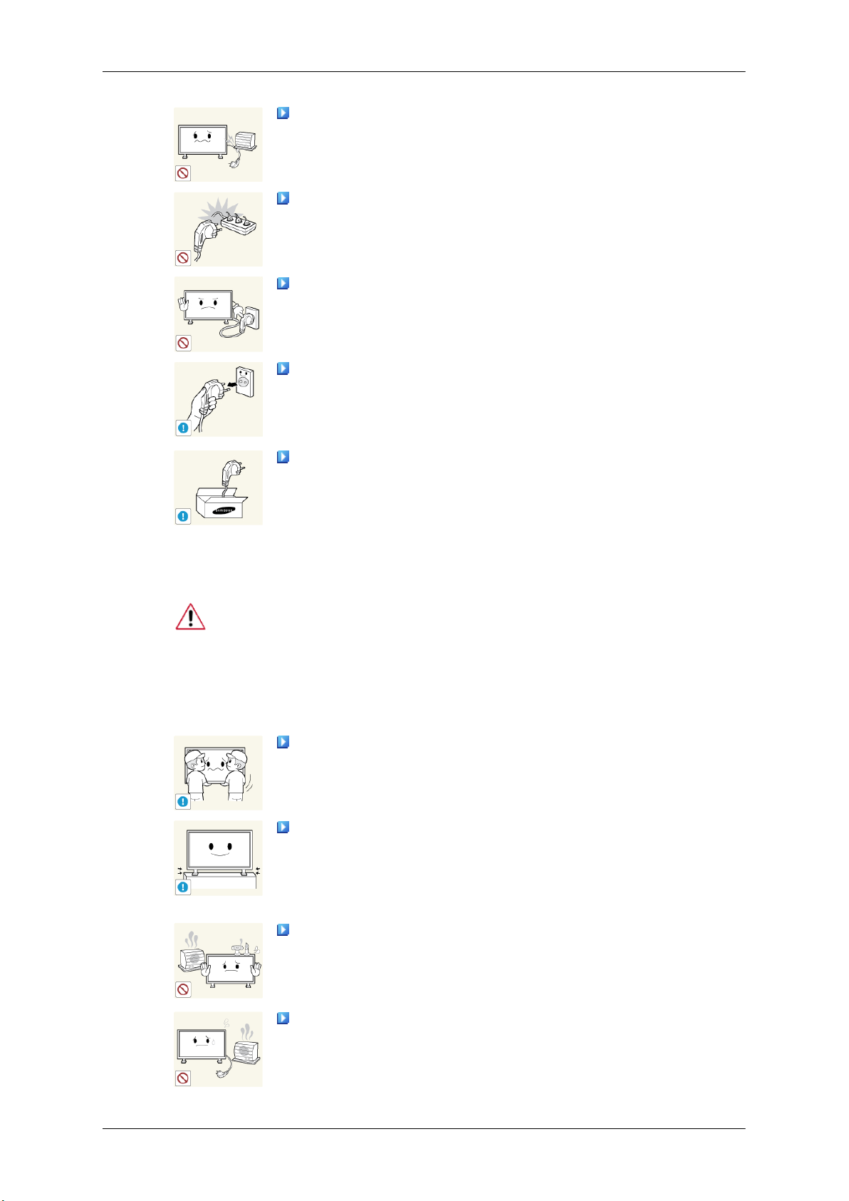
Do not forcefully bend or pull the power plug and do not place any
heavy material on it.
• Otherwise, this may result in fire.
Do not connect multiple appliances to the same power outlet.
• Otherwise, this may cause fire due to overheating.
Do not disconnect the power cord while using the product.
• Otherwise, this may result in damage to the product due to electric
shock.
To disconnect the apparatus from the mains, the plug must be pulled
out from the mains
erable.
• Otherwise, this may cause electric shock or fire.
Use only the power cord provided by our company. Do not use the
provided power cord of another product.
socket, therefore the mains plug shall be readily op-
Installation
• Otherwise, this may result in fire or electric shock.
Be sure to contact an authorized Service Center when installing your
a location with heavy dust, high or low temperatures, high humidity, and exposed
to chemical substances and where it operates for 24 hours such as at airports,
train stations etc.
Failure to do so may cause serious damage to your monitor.
Ensure that at least two persons lift and move the product.
• Otherwise, it may be
age the product.
When installing the product in a cabinet or rack, make sure that the
front end of the bottom of the product does not project out.
• Otherwise, it may fall or cause personal injury.
• Use a cabinet or rack of a size appropriate to the product.
DO NOT PLACE CANDLES, MOSQUITO REPELLANT, CIGARETTES AND ANY HEATING
UCT.
dropped and cause personal injury, and/or dam-
APPLIANCES NEAR THE PROD-
monitor in
• Otherwise, this may result in fire.
Keep heating appliances as far away from the power cord or the product as possible.
• Otherwise, this may result in electric shock or fire.
Page 4
Safety Instructions
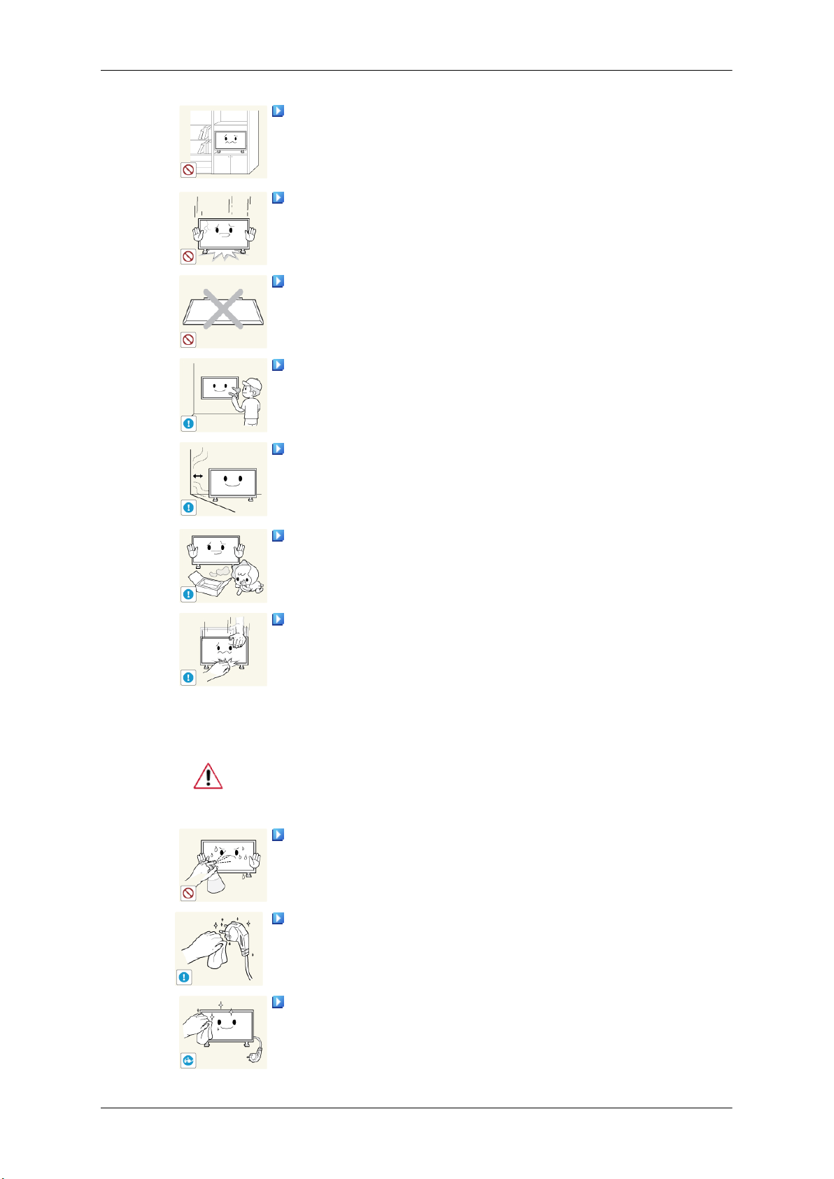
Do not install it in a badly ventilated location such as a bookcase or
closet.
• Otherwise, this may result
temperature.
When putting the product down, make sure to put it down softly.
• Otherwise, this may result in damage to the screen display.
Do not place the front of the product on the floor.
• Otherwise, this may result in damage to the screen display.
Ensure that an authorized installation company installs the wall mount.
• Otherwise, it may fall and cause personal injury.
• Make sure to install the specified wall mount.
Install your product in a well ventilated location. Ensure that there is
a clearance of more than 4 inches (10 cm) from the wall.
• Otherwise, it may result in fire due to an increase in the internal tem-
perature.
Ensure that the packaging vinyl is kept away from children.
in fire due to an increase in the internal
Clean
• Otherwise, it may result in serious harm (suffocation) if children play
with it.
If the height of your monitor is adjustable, do not place any object or
part of your body on the stand when lowering it.
• This may cause damage to the product or the person carrying it.
When cleaning the PDP Display case or the surface of the TFT-PDP screen, wipe
with a slightly moistened, soft fabric..
Do not spray cleaner directly onto the surface of the product.
• Otherwise, this may result
structure and the screen surface may peel off.
When cleaning the power plug pins or dusting the power outlet, clean
it with a dry cloth.
• Otherwise, it may result in fire.
in the discoloration and distortion of the
When cleaning the product, make sure to disconnect the power cord.
Otherwise, it may result in electric shock or fire.
•
Page 5
Safety Instructions
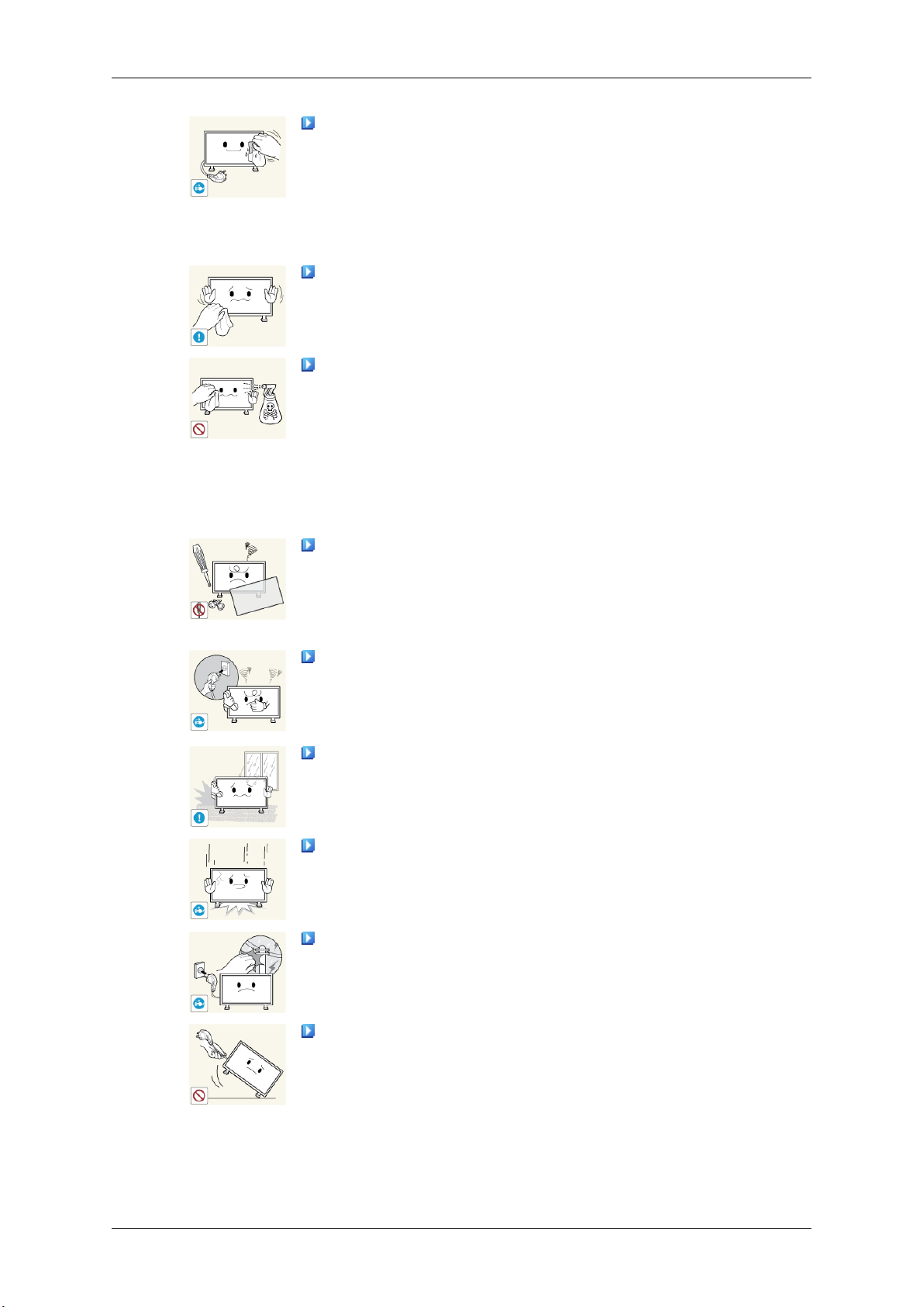
When cleaning the product, disconnect the power cord and clean it with
a soft, dry cloth.
Others
• Do not use chemicals
quito repellant, lubricant, or cleaner.
• These may change the appearance of the product surface and peel off
the indication labels on the product.
Since the product housing is easily scratched, make sure to use the
specified cloth only.
When cleaning the product, do not spray water directly onto the main
body of the product.
• Ensure that water does not enter the product and that it is not wet.
• Otherwise, this may result in electric shock, fire or a malfunction.
The product is a high voltage product. Do not disassemble, repair or
modify the product yourself.
• Otherwise, this may result in electric shock or fire.
such as wax, benzene, alcohol, thinner, mos-
• If the product needs to be repaired, contact a Service Center.
If there is a strange smell or a strange sound or smoke is coming from
the product, disconnect the
Center.
• Otherwise, this may result in electric shock or fire.
Do not place this product in a location exposed to moisture, dust,
smoke, water, or in a car.
• Otherwise, this may result in electric shock or fire.
When you drop the product or the case is broken, turn the power off
and disconnect the power cord. Contact a Service Center.
• Otherwise, this may result in electric shock or fire.
If thunder or lightning is occurring, do not touch the power cord or
antenna cable.
• Otherwise, this may result in electric shock or fire.
Do not try to move the monitor by pulling only the wire or the signal
cable.
power plug immediately and contact a Service
• Otherwise, it may fall
product or fire due to damage to the cable.
and result in electric shock, damage to the
Page 6
Safety Instructions
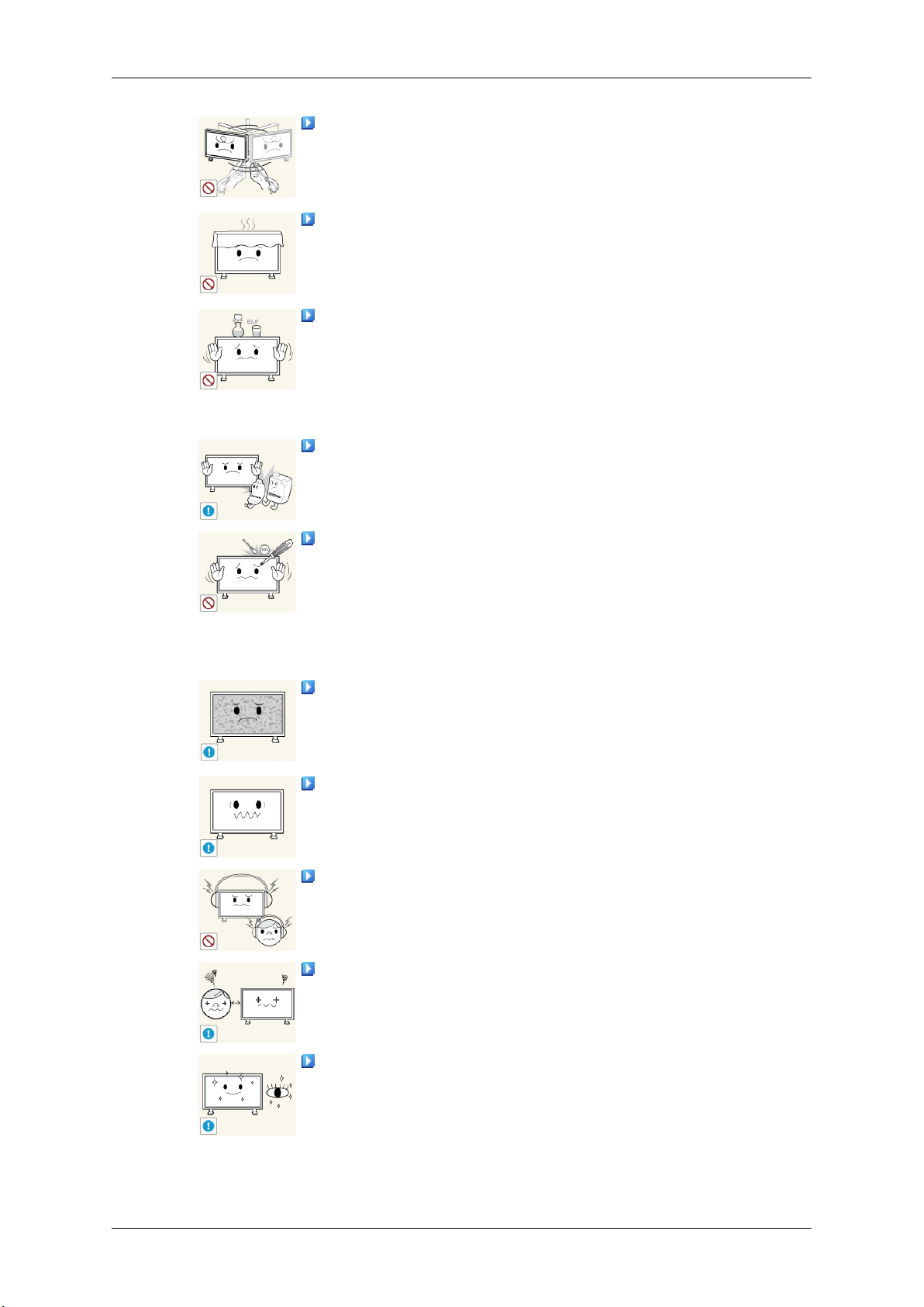
Do not lift or move the product back and forwards or right and left
while only holding the power cord or signal cables.
• Otherwise, it may fall
product or fire due to damage to the cable.
Make sure that the ventilating opening is not blocked by a table or
curtain.
• Otherwise, it may result
perature.
Do not place any containers containing water, vases, flowerpots, medicines as well as any metal on the product.
• If water or a
cord and contact a Service Center.
• This may result in a product malfunction, electric shock, or fire.
Do not use or keep combustible spray or flammable material near the
product.
• Otherwise, this may result in an explosion or fire.
Do not insert any metal, such as chopsticks, coins, pins and steel, or
flammable objects, such as
the ventilating openings, input and output terminals, etc).
• If water or foreign material enters the product, disconnect the power
cord and contact a Service Center.
foreign material enters the product, disconnect the power
and result in electric shock, damage to the
in fire due to an increase in the internal tem-
matches or paper, inside the product (through
• Otherwise, this may result in electric shock or fire.
When using a fixed screen for a long time, an afterimage or stain may
occur.
• If you are not
sleep mode or use a moving screen saver.
Set a resolution and frequency appropriate to the product.
• Otherwise, your eyesight may be damaged.
When using headphones or earphones, do not turn the volume too high.
• Having the sound too loud may damage your hearing.
To avoid eyestrain, do not sit too close to the product.
Take a rest for at least five (5) minutes after using the monitor for one
(1) hour.
using your product for a long period of time, put it into
• This reduces eye fatigue.
Page 7
Safety Instructions
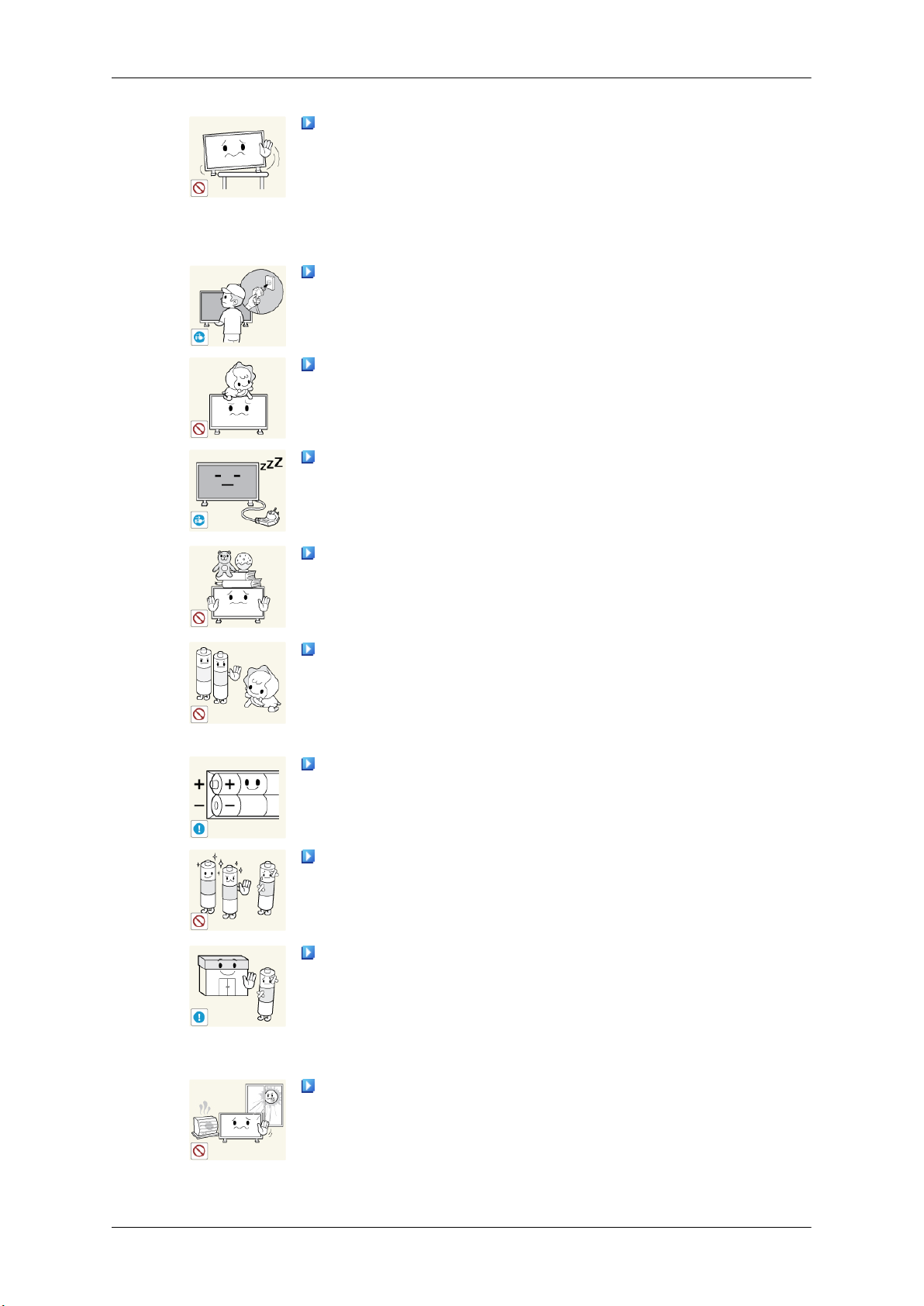
Do not install it in an unstable location such as an unstable rack or
uneven surface or a location exposed to vibrations.
• Otherwise, it may fall
product.
• If you use the product in a location exposed to vibrations, it may
damage the product and result in fire.
When moving the product, turn the power off and disconnect the power
plug, antenna cable, and all the cables connected to the product.
• Otherwise, it may result in electric shock or fire.
Ensure that children do not hang onto the product or climb up onto the
product.
• The product may fall and cause personal injury or death.
If you do not use the product for a long period of time, disconnect the
power cord from the power outlet.
• Otherwise, this may result in overheating or fire due to dust, and may
result in fire due to electric shock or leakage.
Do not place any heavy items or toys or confectionery, such as cookies
etc. that may attract the attention of children and to the product.
• Your children may hang onto the product causing it to fall and this
may result in personal injury or death.
Be careful that children do not place the battery in their mouths when
removed from the remote control. Place the battery in a location that
children or infants cannot reach.
and cause personal injury and/or damage the
• If children have had the battery in their mouths, consult your doctor
immediately.
When replacing the battery, insert it with the right polarity (+, -).
• Otherwise, the battery may become damaged or it may cause fire,
personal injury or damage due to leakage of the internal liquid.
Use only the specified standardized batteries, and do not use a new
battery and a used battery at the same time.
• Otherwise, the batteries may
jury or damage due to a leakage of the internal liquid.
The batteries (and rechargeable batteries) are not ordinary refuse and
must be returned for
returning the used or rechargeable batteries for recycling.
• The customer can return used or rechargeable batteries to a nearby
public recycling center or to a store selling the same type of the battery
or rechargeable battery.
Do not place the product in a location exposed to direct sunlight or
near any heat such as a fire or heater.
• This may reduce the lifetime of the product, and may result in fire.
recycling purposes. The customer is responsible for
be damaged or cause fire, personal in-
Page 8
Safety Instructions
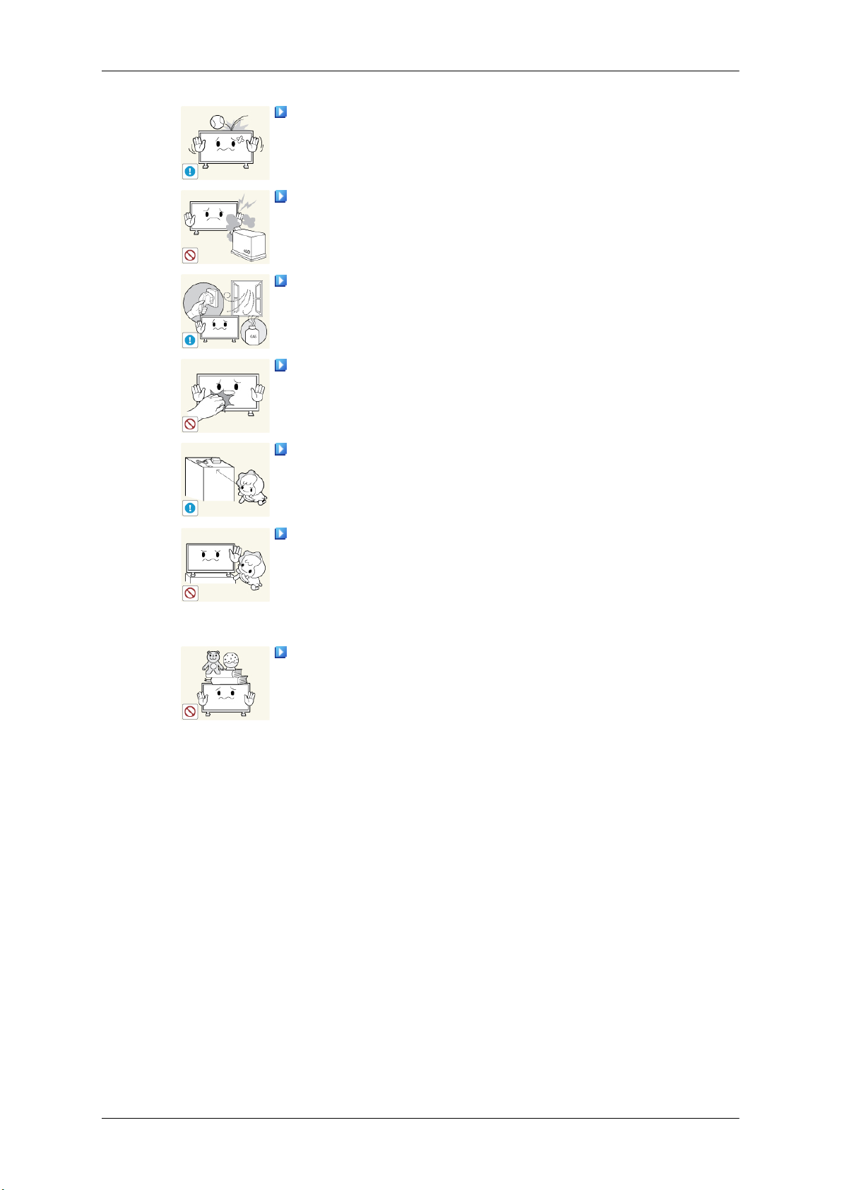
Do not drop any objects onto the product or cause any impact to the
product.
• Otherwise, this may result in electric shock or fire.
Do not use a humidifier near the product.
• Otherwise, this may result in electric shock or fire.
When there is a gas leak, do not touch the product or the power plug;
ventilate immediately.
• If a spark occurs, it may cause an explosion or fire.
If the product has been turned on for a long time, the display panel
becomes hot. Do not touch it.
Keep the small accessories in a location out of the reach of children.
Do not install the product in a location low enough for children to
reach.
• Otherwise, it may fall and result in personal injury.
• Since the
level and stable surface.
Do not put any heavy objects on the product.
• This may result in personal injury and/or damage to the product.
front part of the product is heavy, install the product on a
Page 9
Introduction
Package Contents
Note
Please make sure the following items are included with your PDP Display.
If any items are missing, contact your dealer.
Contact a local dealer to buy optional items.
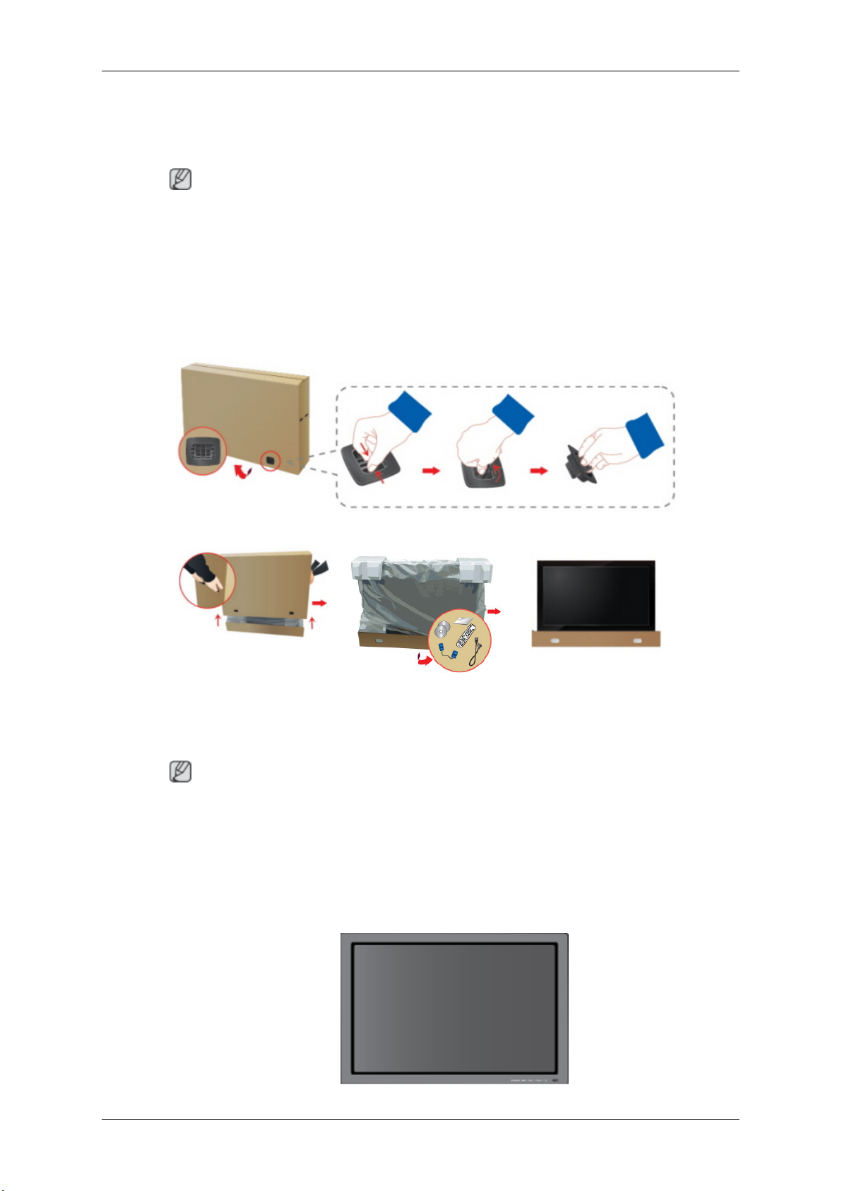
Checking the Contents of the Package
Remove the lock from the package box, as shown in the figure above.
holding the grooves on both
• After unpacking the package, make sure to check the contents of the package.
• Make sure to keep the package box for transporting the product in the future.
• After
Unpacking
Lift up the package box by
sides of the package box.
Note
unpacking, you may use the lower part of the package box as a temporary stand for product
test or operation check.
Check the contents of the
package.
Remove the Styrofoam and
vinyl cover.
Page 10
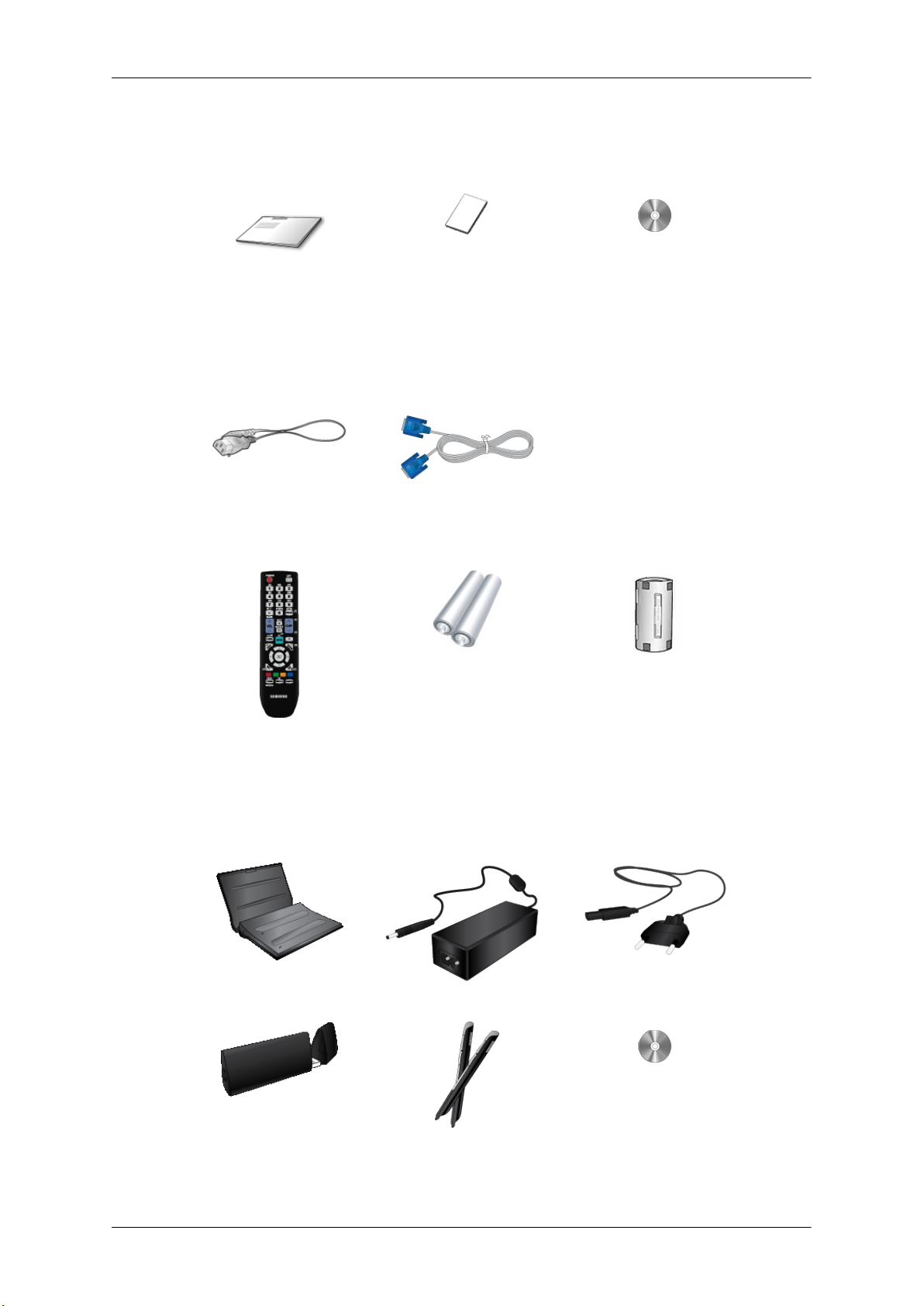
Manuals
Introduction
PDP Display
Quick Setup Guide Warranty Card
(Not available in all loca-
Cables
Power Cord D-Sub Cable
Others
Remote Control Batteries (AAA X 2)
User's Guide
tions)
Ferrite Core for Power Cord
(Not available in all loca-
tions)
Options (P64FT Model Only)
Pen battery charger(IWB-C1) Adapter Power Cord
USB Dongle(IWB-D1) Zigbee Touch Pen(IWB-P1) Samsung Interactive white-
board
Page 11

Introduction
Pen battery charger(IWB-C1), USB Dongle(IWB-D1), Zigbee Touch Pen(IWB-P1) only in P64FT model
NOTE: This equipment has been tested and found to comply with the limits for a Class B digital device,
pursuant to part 15 of the FCC Rules. These limits are designed to provide reasonable protection against
harmful interference in a residential installation. This equipment generates, uses and can radiate radio
frequency energy and, if not installed and used in accordance with the instructions, may cause harmful
interference to radio communications. However, there is no guarantee that interference will not occur in a
particular installation. If this equipment does cause harmful interference to radio or television reception,
which can be determined by turning the equipment off and on, the user is encouraged to try to correct the
interference by one or more of the following measures:
—Reorient or relocate the receiving antenna.
—Increase the separation between the equipment and receiver.
—Connect the equipment into an outlet on a circuit different from that to which the re-ceiver is connected.
—Consult the dealer or an experienced radio/ TV technician for help.
Warning : This equipment may generate or use radio frequency energy. Changes or modifications to this
equipment may cause harmful interference unless the modifications are expressly approved in the instruction
manual. The user could lose the authority to operate this equipment if an unauthorized change or modification
is made.
This device complies with Part 15 of the FCC's Rules. Operation is subject to the following two Conditions :
1. This device may not cause harmful interference. and
2. This device must accept ant interference received, including interference that may cause undesirable operation.
Page 12
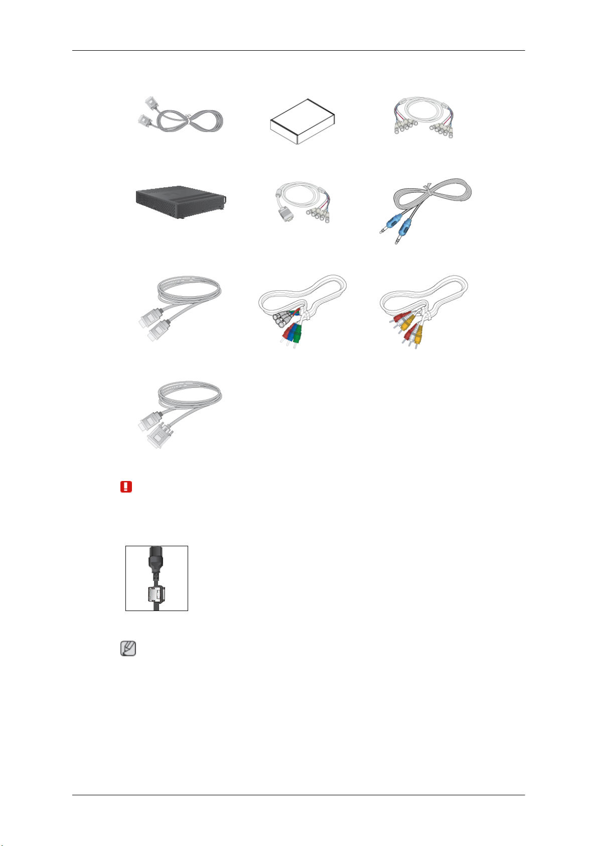
Sold separately
DVI Cable Wall Mount KIT BNC to BNC Cable
Network Box RGB to BNC Cable STEREO Cable
Introduction
HDMI Cable BNC-COMPONENT Cable COMPOSIT Cable
HDMI-DVI Cable
Warning
• The network box is not compatible with the Interactive Whiteboard program.
Ferrite Core
Your PDP Display
Note
• The ferrite cores are used to shield the cables from interference.
• When connecting a cable,
cable near the plug.
open the ferrite core and clip it around the
The PDP device may interfere with an amateur radio or AM radio.
Page 13

Front
Introduction
SOURCE button [SOURCE]
Switches from PC mode
external devices that are connected to the PDP Display at the time.
[PC] → [DVI] → [AV] → [HDMI] → [MagicInfo] → [Component] →
[BNC]
Enter button [
Activates a highlighted menu item.
Note
• This product is not compatible with MagicInfo.
MENU button [MENU]
Opens the on-screen menu
or return to the previous menu.
- VOL+
Moves from one menu item to another horizontally or adjusts selected menu values. When OSD is not on the screen, push the button to adjust volume.
SEL
Moves from one menu item to another vertically or adjusts selected menu values.
Power button [ ]
]
to Video mode. Changing the source is only allowed for
and exits from the menu. Also use to exit the OSD menu
Use this button for turning the PDP Display on and off.
Power indicator
Shows PowerSaver mode by blinking green
Note
See PowerSaver described in the manual for further information regarding power
saving functions. For energy conservation, turn your PDP Display OFF when it is
not needed or when leaving it unattended for long periods.
Remote Control Sensor
Aim the remote control towards this spot on the PDP Display.
Page 14

Rear
Introduction
Note
For detailed information concerning
PDP Display's configuration at the back may vary slightly depending on the PDP Display model.
cable connections, refer to Connecting Cables under Setup. The
POWER IN
The power cord plugs
the wall plug.
into the PDP Display and
RS232C OUT/IN (RS232C Serial PORT)
MDC(Multiple Display Control) Program Port
RGB IN (PC Connection Terminal (Input))
• Use a D-Sub Cable
(Analog PC)
• Connect the RGB IN port on the monitor to
the BNC port on the PC using the RGB to
BNC cable.
DVI IN (PC Video Connection Terminal)
Connect the [DVI IN]
DVI port on the PC using the DVI cable.
(15 pin D-Sub) - PC mode
port on the monitor to the
Page 15
Introduction
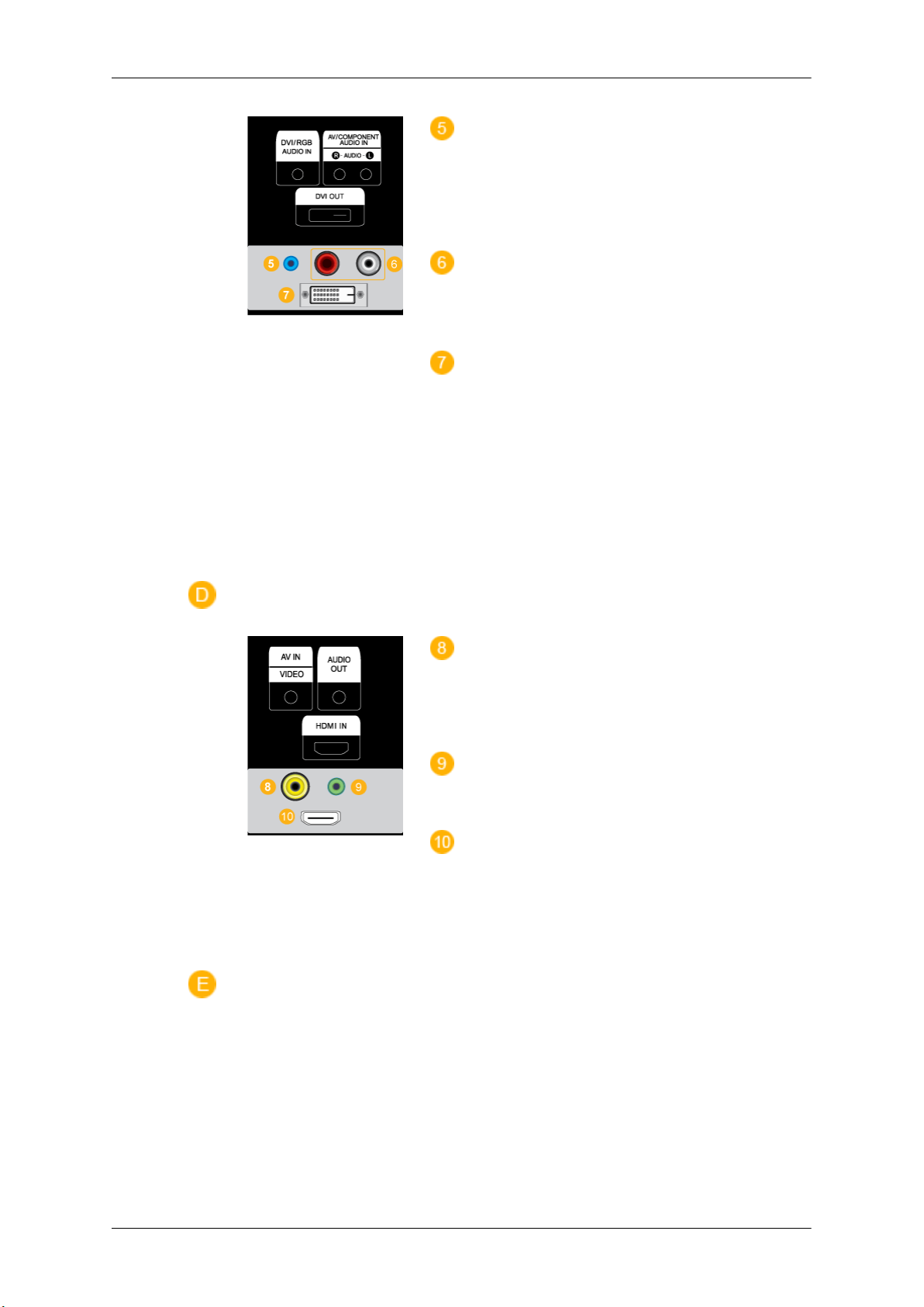
DVI/RGB AUDIO IN(PC/DVI Audio Con-
nection Terminal (Input))
Connect an audio cable
monitor and the audio out port on the source device.
AV/COMPONENT AUDIO IN [R-AUDIO-L]
Connect an audio cable
monitor and the audio out port on the source device.
DVI OUT
• Connect a monitor to
a DVI cable.
• Connect the [DVI OUT] port on the monitor
to the [HDMI IN] port on the other monitor
using the DVI to HDMI cable.
• DVI, HDMI and network signals sent via the
[DVI OUT] port are displayed on the second
display which has the DVI IN port.
to [R-AUDIO-L] on the
to [R-AUDIO-L] on the
another monitor through
AV IN [VIDEO]
Connect the [AV IN
monitor to the video output terminal of the external device using a VIDEO cable.
AUDIO OUT
Headphone/External speaker output terminal.
HDMI IN
Connect the HDMI terminal
PDP Display to the HDMI terminal of your digital
output device using a HDMI cable.
Up to HDMI cable 1.2 can be supported.
(VIDEO)] terminal of your
at the back of your
Page 16

Introduction
BNC OUT [R, G, B, H, V] (BNC Terminal
(Output))
BNC (Analog PC) Connection:
G, B, H, V ports.
The number of PDP Displays that can be connected to the loopout depends on the cables, signal
source, etc. With cables or signal source where
there is no degradation, up to 10 PDP Displays
can be connected (May not be supported depending on the connected cable).
BNC/COMPONENT IN [R/PR, G/Y,
V] (BNC/Component Connection Terminal (input))
- During BNC input, please check specifications
for the input ports below.
• [R/PR] --> Red port input
• [G/Y] --> Green port input
• [B/PB] --> Blue port input
- During component input, please check specifi-
cations for the input ports below.
connecting the R,
B/PB, H,
Remote Control
Note
• [R/Y] --> Green port input
• [G/PB] --> Blue port input
• [B/PR] --> Red port input
This product has an internal speaker.
The performance of the
near the PDP Display , causing a malfunction due to interference with the frequency.
remote control may be affected by a TV or other electronic device operating
Page 17

Introduction
POWER
OFF
Number Buttons
DEL / GUIDE button
- VOL +
SOURCE
D.MENU
TOOLS
Up-Down Left-Right buttons
INFO
COLOR BUTTONS
TTX/MIX
MTS/DUAL
ENTER/PRE-CH
MUTE
CH/P
TV
MENU
RETURN
EXIT
MagicInfo
1. POWER
2. OFF
3. Number Buttons Used to enter the
4. DEL
/ GUIDE button
Turns the product On.
Turns the product Off.
MagicInfo.
The "-" button is used to select Digital channels.
Electronic Program Guide (EPG) display.
password during the OSD adjustment or to use
Note
- This button is disabled for this PDP display.
5. - VOL + Adjusts the audio volume.
6. SOURCE
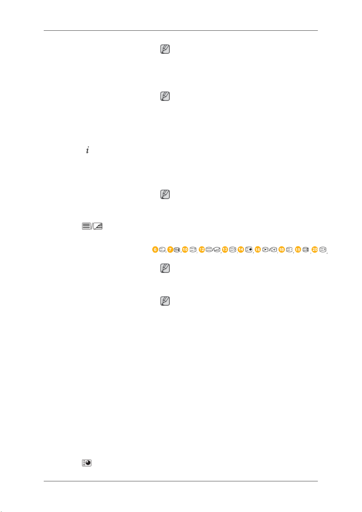
7.
D.MENU DTV menu display
Press this button to
nected external input source.
switch to MagicInfo or PC mode or a con-
Page 18
Introduction
Note
- This button is disabled for this PDP display.
8. TOOLS
Up-Down Left-Right buttons
9.
10.
11. COLOR BUTTONS Press to add or delete channels and to store channels to the favorite
12.
INFO
TTX/MIX
Use to quickly select frequently used functions.
Note
- This button is disabled for this PDP display.
Moves from one menu item to another horizontally, vertically or
adjusts selected menu values.
Current picture information is
of the screen.
channel list in the “Channel List” menu.
Note
- This button is disabled for this PDP display.
TV channels provide written information services via teletext.
- Teletext Buttons
displayed on the upper left corner
13. MTS/DUAL
Note
- This button is disabled for this PDP display.
Note
- This button is disabled for this PDP display.
MTS-
You can select MTS (Multichannel Television Stereo) mode.
Audio Type MTS/S_Mode Default
FM Stereo Mono Mono Manual Change
Stereo
SAP
DUAL-
STEREO/MONO,
MONO/NICAM STEREO can be operated depending on the
broadcasting type by using the DUAL button on the remote control
while watching TV.
DUAL l /
Mono ↔ Stereo
Mono ↔ SAP
DUAL ll and MONO/NICAM
Mono
14.
ENTER/PRE-CH
This button is used
to return to the immediately previous channel.
Page 19

Introduction
Note
- This button is disabled for this PDP display.
15. MUTE
CH/P In TV mode, selects TV channels.
16.
17. TV Selects the TV mode directly.
18. MENU Opens the on-screen menu
19.
20. EXIT
21. MagicInfo MagicInfo Quick Launch Button.
RETURN
Pauses (mutes) the audio
the lower left corner of the screen. The audio comes back on if
MUTE or - VOL + is pressed in the Mute mode.
Note
- This button is disabled for this PDP display.
Note
- This button is disabled for this PDP display.
adjustment menu.
Returns to the previous menu.
Exits from the menu screen.
output temporarily. This is displayed on
and exits from the menu or closes the
User Installation Guide
Note
• Be sure to call an installation expert of Samsung Electronics to install the product.
• The warranty
authorized by Samsung Electronics.
• A Samsung Electronics service center can provide details.
becomes invalid if the product is installed by someone other than a professional
Note
This button is disabled
fo.
for products that do not support MagicIn-
Page 20
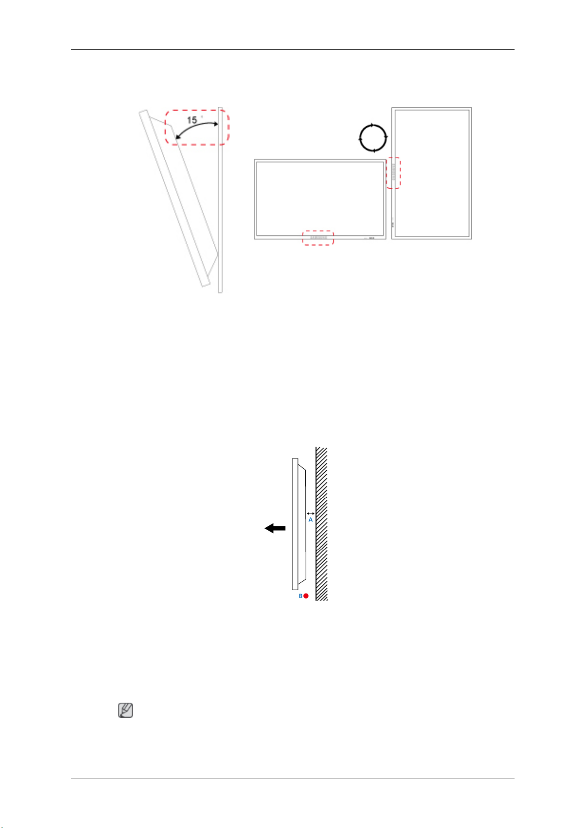
Tilt Angle and Rotation
1 2
1. The product can be tilted up to 15 degrees from a vertical wall.
Introduction
2. To use the product in portrait mode, rotate it clockwise so that the LED indicator is at the bottom.
Ventilation requirement
1. Vertical wall mount condition
<Side view>
A : min. 40 mm
B: Ambient temperature Measuring point < 35°C
• When installing the product onto a vertical wall, be sure there is a 40 mm space or more behind
the product for
Note
A Samsung Electronics service center can provide details.
ventilation, as shown above, and maintain the ambient temperature at 35°C or lower.
Page 21

2. Embedded Mount guide
<Side view> <Top view>
Introduction
A : min. 40 mm
B : min. 70 mm
C : min. 50 mm
D : min. 50 mm
E : Ambient temperature Measuring point < 35°C
• When embedding the product in a wall, be sure there is some space behind the product for ventilation, as shown above, and maintain the ambient temperature at 35°C or lower.
Note
A Samsung Electronics service center can provide details.
3. Floor mount guide
<Side view>
A: min. 50 mm
B: Ambient temperature Measuring point < 20°C
• When embedding the product in the floor, be sure there is a 50 mm space or more behind the product
for ventilation, as shown above, and maintain the ambient temperature at 20 °C or lower.
Note
A Samsung Electronics service center can provide details.
Page 22

Mechanical Layout
* Unit: mm
Introduction
Installation VESA Bracket
• When installing VESA, make sure to comply with the international VESA standards.
• Purchasing VESA
Distributor to place an order. After your order is placed, installation professionals will visit you
and install the bracket.
• At least 2 persons are needed in order to move the PDP Display.
• SAMSUNG is not responsible for any product damage or any injury caused by installation at
customer's discretion.
Bracket and Installation Information : Please contact your nearest SAMSUNG
Dimensions
* Unit: mm
Notice
For securing the bracket
on a wall, use only machine screws of 6 mm diameter and 8 to 12 mm length.
Page 23
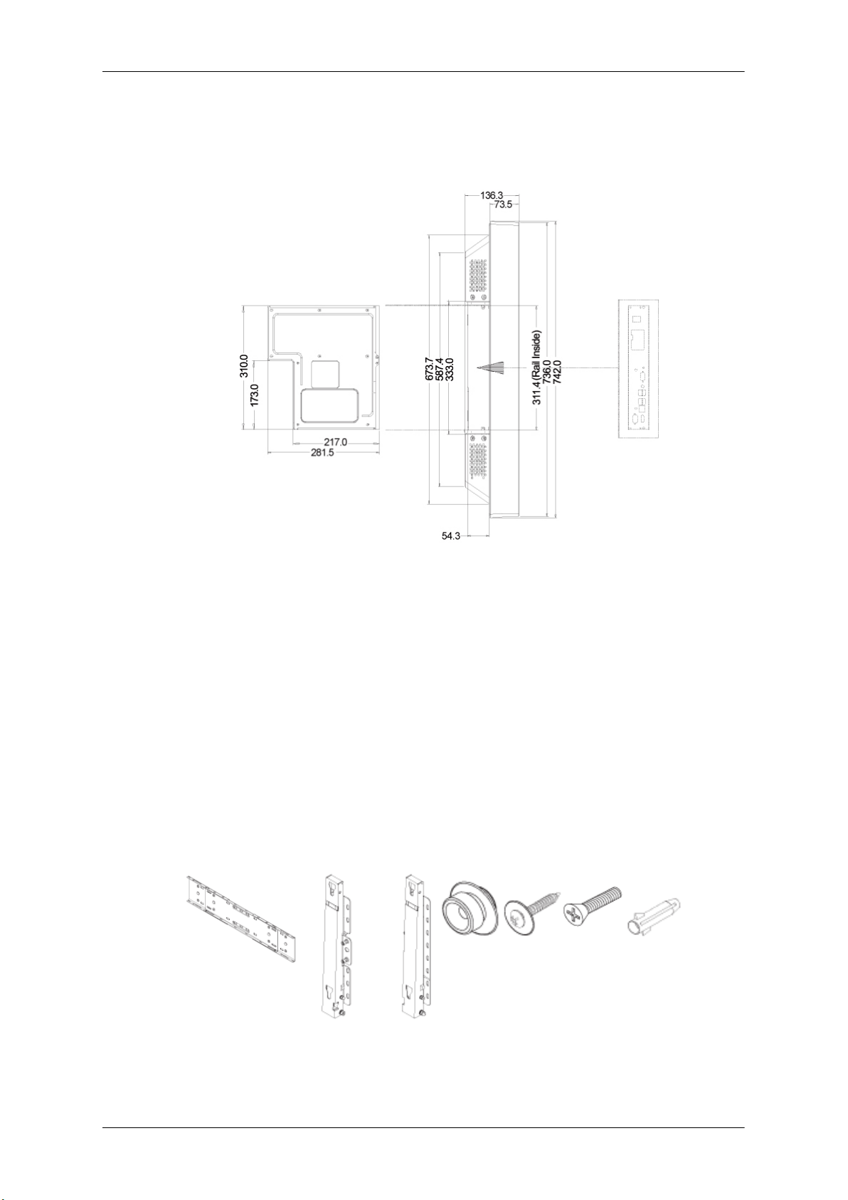
Accessories (sold separately)
• Dimension with other accessories
Introduction
* Unit: mm
Wall Bracket Installation
•
Contact a technician for installing the wall bracket.
• SAMSUNG Electronics
when the installation is done by the customer.
• This product is for installing on cement walls. The product may not stay in place when installed
on plaster or wood.
Components
Only use the components and accessories shipped with the product.
is not responsible for any damages to the product or harm to customers
Wall Bracket(1) Hinge(Left 1, Right1)Plastic
Hanger
(4)
Screw
(A)(11)
Screw(B)
(4)
Anchor
(11)
Page 24
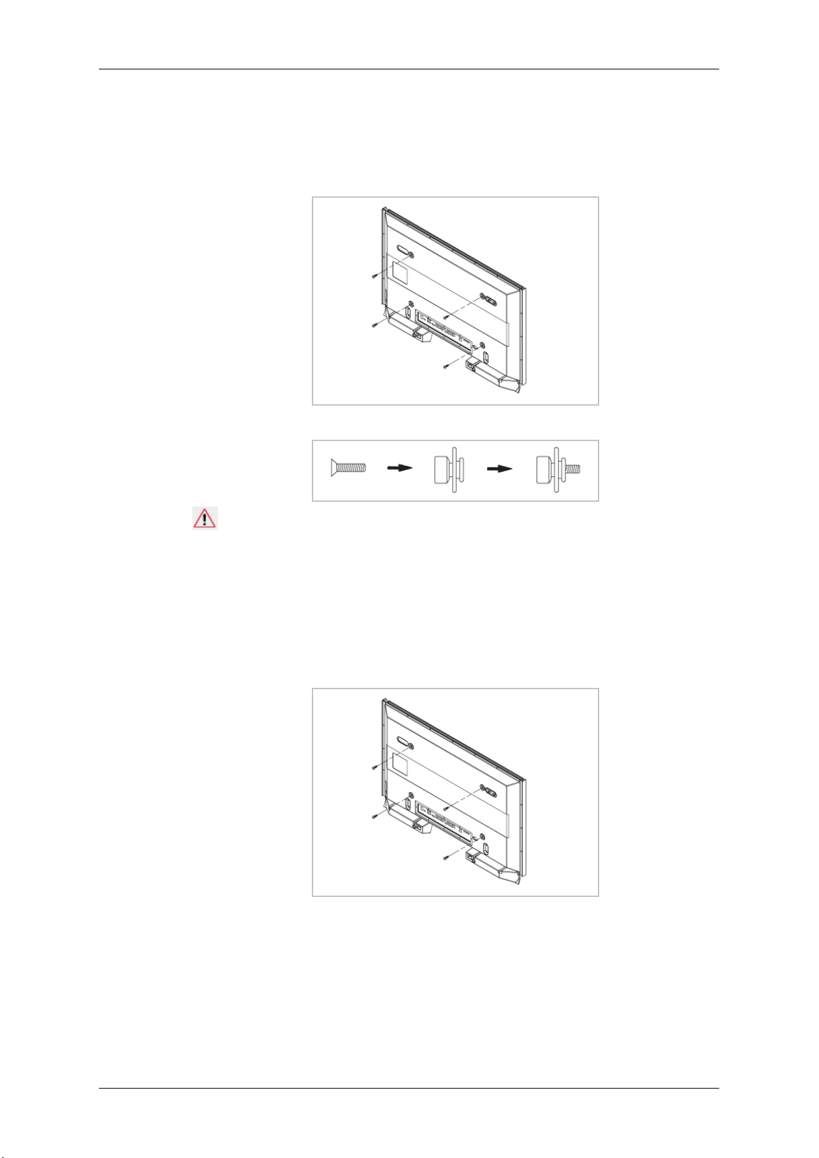
Introduction
To mount the product on the wall bracket
The shape of the
the screw are the same)
1. Remove the 4 screws on the back of the product.
2. Insert the screw B into the plastic hanger.
product may vary depending on the model. (The assemblies of the plastic hanger and
Notice
• Mount the product on
plastic hangers.
• Be careful when installing the product on the bracket as fingers can be caught in the holes.
• Make sure the wall bracket is securely fixed to the wall, or the product may not stay in place
after installation.
3. Tighten the 4 screws in step 2 (plastic hanger + screw B) to the rear holes of the product.
4. Remove safety pin (3)
Then place the product(2) so that it is firmly fixed to the bracket. Make sure to re-insert and tighten
the safety pin (3) to securely hold the product to the bracket.
the wall bracket and make sure it is properly fixed to the left and right
and insert the 4 product holders into the corresponding bracket holes (1).
Page 25
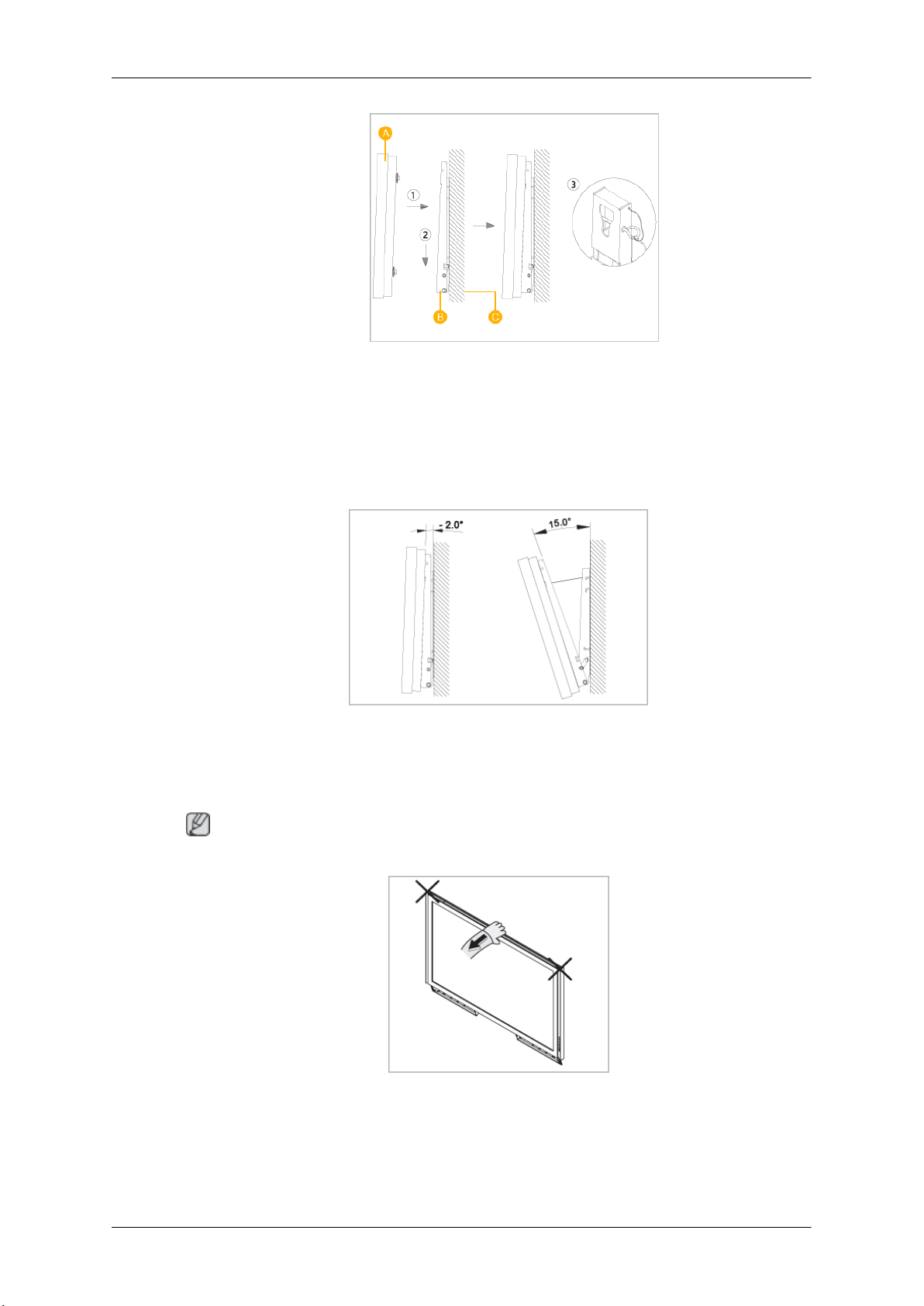
A - PDP Display
B - Wall Bracket
C - Wall
Wall Bracket Angle Adjustment
Adjust the bracket angle to -2° before installing it on the wall.
Introduction
1. Fix the product to the wall bracket.
2. Hold the product at
angle.
Note
You can adjust the bracket angle between -2° and 15°.
Make sure to use the top center, and not the left or the right side of the product to adjust the angle.
the top in the center and pull it forward (direction of the arrow) to adjust the
Page 26
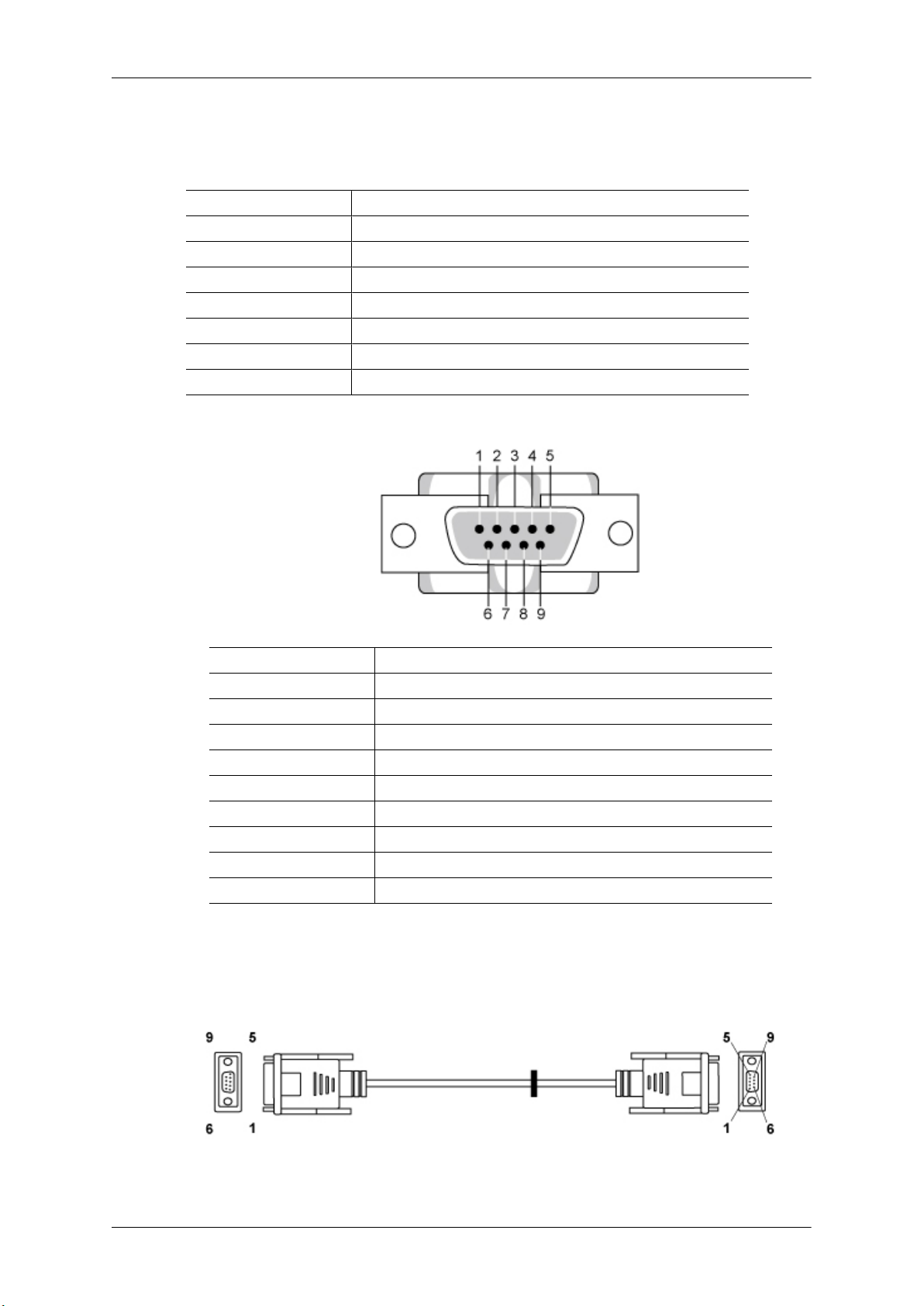
Remote Control (RS232C)
Cable connections
interface RS232C(9 pin)
pin TxD(No.2) RxD(No.3) GND(No.5)
Bits rate 9600 bps
Data Bits 8 bit
Parity None
Stop Bits 1 bit
Flow control None
Maximum length 15 m (only shielded type)
• Pin assignment
Introduction
Pin Signal
1 Data Carrier Detect
2 Received Data
3 Transmitted Data
4 Data Terminal Ready
5 Signal Ground
6 Data Set Ready
7 Request to Send
8 Clear to Send
9 Ring Indicator
• RS232C cable
Connector : 9-pin D-Sub
Cable : Cross (reversed) cable
-P1- -P1- -P2- -P2-
FEMALE Rx 2 ---------> 3 Rx FEMALE
Page 27
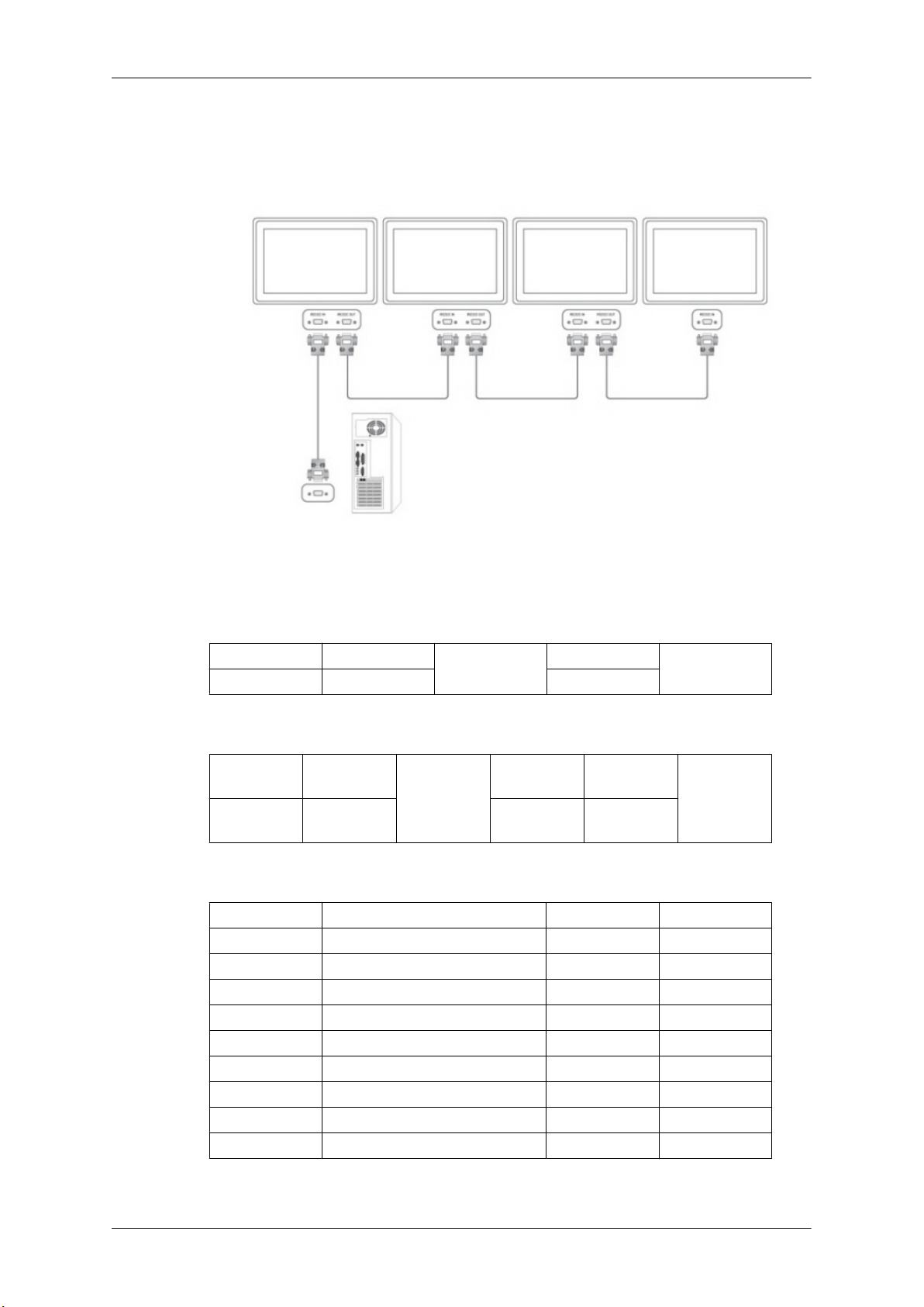
Introduction
• Connecting method
Tx
Gnd
3
5
<---------
----------
2
5
Tx
Gnd
Control codes
• Get control
• Set control
• commanding words
No. command type command Value range
1 Power control 0x11 0~1
2 Volume control 0x12 0~100
3 Input source control 0x14 4 Screen Mode control 0x18 5 Screen Size control 0x19 0~255
6 PIP on/off control 0x3C 0~1
7 Auto adjustment control 0x3D 0
8 Video wall Mode control 0x5C 0~1
9 Safety Lock 0x5D 0~1
Header
0xAA command type 0
Header command
0xAA command
command
ID
ID
type
DATA Length
DATA
Length
1 Value
CheckSum
DATA
CheckSum
- ID should show hexadecimal value of assigned ID, but ID 0 should be 0xFF.
Page 28
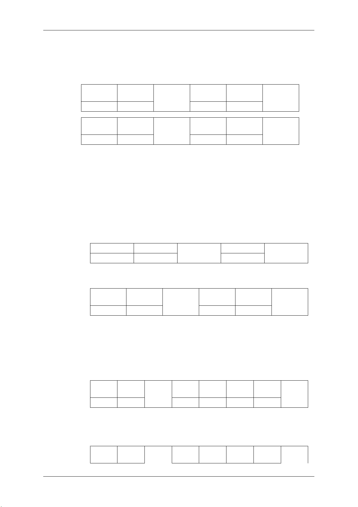
Introduction
- Every communication will be made in hexadecimals and Checksum is the sum of all remainings.
If it exceeds two digits,for example, it is 11+FF+01+01=112, discard the number in the first digit
like below.
example)PowerOn&ID=0
Header command
ID
0xAA 0x11 1 Power
Header command
ID
0xAA 0x11 1 1
If you want to control every mechanism connected with Serial Cable regardless of its ID, set ID
part to "0xFE" and
not respond with ACK.
• Power Control
• Function
Personal Computer turns TV / Monitor power ON/OFF.
• Get Power ON/OFF Status
Header
0xAA 0x11 0
send commands. At the time, each product will follow commands but it will
command
DATA
Length
DATA
Length
ID
DATA 1
CheckSum
DATA 1
12
DATA Length
CheckSum
• Set Power ON/OFF
Header command
ID
0xAA 0x11 1 Power
Power : Power code to be set on TV / Monitor
1 : Power ON
0 : Power OFF
•
Ack
Header
0xAA 0xFF 3 ‘A’ 0x11 Power
Power : Same as above
• Nak
Header command
command
ID
ID
DATA
Length
DATA
Length
DATA
Length
Ack/Nak r-CMD Val1
Ack/Nak r-CMD Val1
DATA
CheckSum
Check
Sum
Check
Sum
Page 29

0xAA 0xFF 3 ‘N’ 0x11 ERR
ERR : Error code that shows what occurred error is
• Volume Control
• Function
Personal Computer changes volume of TV / Monitor.
• Get Volume Status
Introduction
Header
0xAA 0x12 0
• Set Volume
Header command
0xAA 0x12 1 Volume
Volume : Volume value code to be set on TV / Monitor (0 ~ 100)
• Ack
Header command
0xAA 0xFF 3 ‘A’ 0x12 Volume
Volume : Same as above
• Nak
command
ID
ID
DATA
Length
ID
Ack/Nak r-CMD Val1
DATA Length
DATA
Length
CheckSum
DATA
CheckSum
Check
Sum
Header command
0xAA 0xFF 3 ‘N’ 0x12 ERR
ERR : Error code that shows what occurred error is
• Input Source Control
• Function
Personal Computer changes input source of TV / Monitor.
• Get Input Source Status
Header
0xAA 0x14 0
ID
command
DATA
Length
Ack/Nak r-CMD Val1
DATA Length
ID
Check
Sum
CheckSum
Page 30
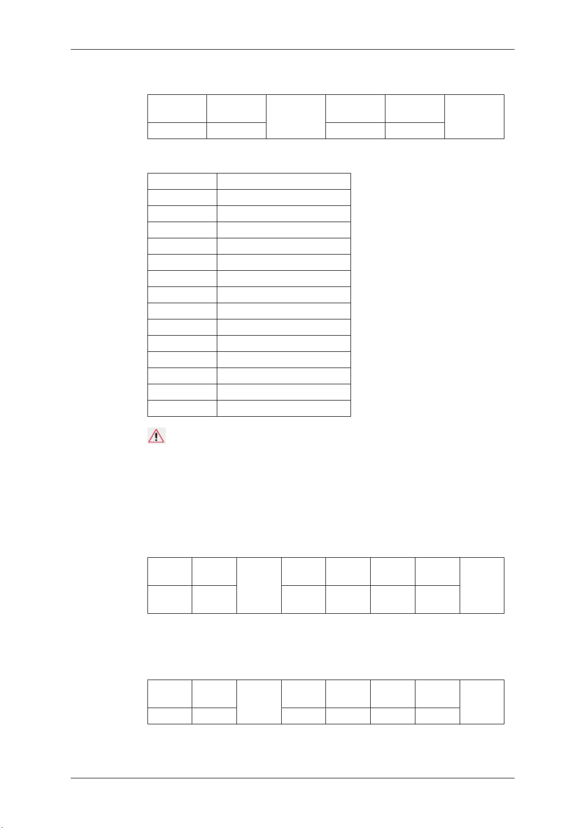
• Set Input Source
Introduction
Header
0xAA 0x14 1 Input Source
Input Source : Input Source code to be set on TV / Monitor
0x14 PC
0x1E BNC
0x18 DVI
0x0C AV
0x04 S-Video
0x08 Component
0x20 MagicInfo
0x1F DVI_VIDEO
0x30 RF(TV)
0x40 DTV
0x21 HDMI1
0x22 HDMI1_PC
0x23 HDMI2
0x24 HDMI2_PC
0x25 DisplayPort
command
ID
DATA
Length
DATA
CheckSum
Caution
DVI_VIDEO, HDMI1_PC, HDMI2_PC → Get Only
In the case of MagicInfo, only possible with models include MagicInfo
In the case of TV, only possible with models include TV.
• Ack
Header
0xAA 0xFF 3 ‘A’ 0x14
Input Source : Same as above
• Nak
Header
0xAA 0xFF 3 ‘N’ 0x14 ERR
command
ID
command
ID
DATA
Length
DATA
Length
Ack/Nak r-CMD Val1
Ack/Nak r-CMD Val1
Input
Source
Check
Sum
Check
Sum
ERR : Error code that shows what occurred error is
Page 31
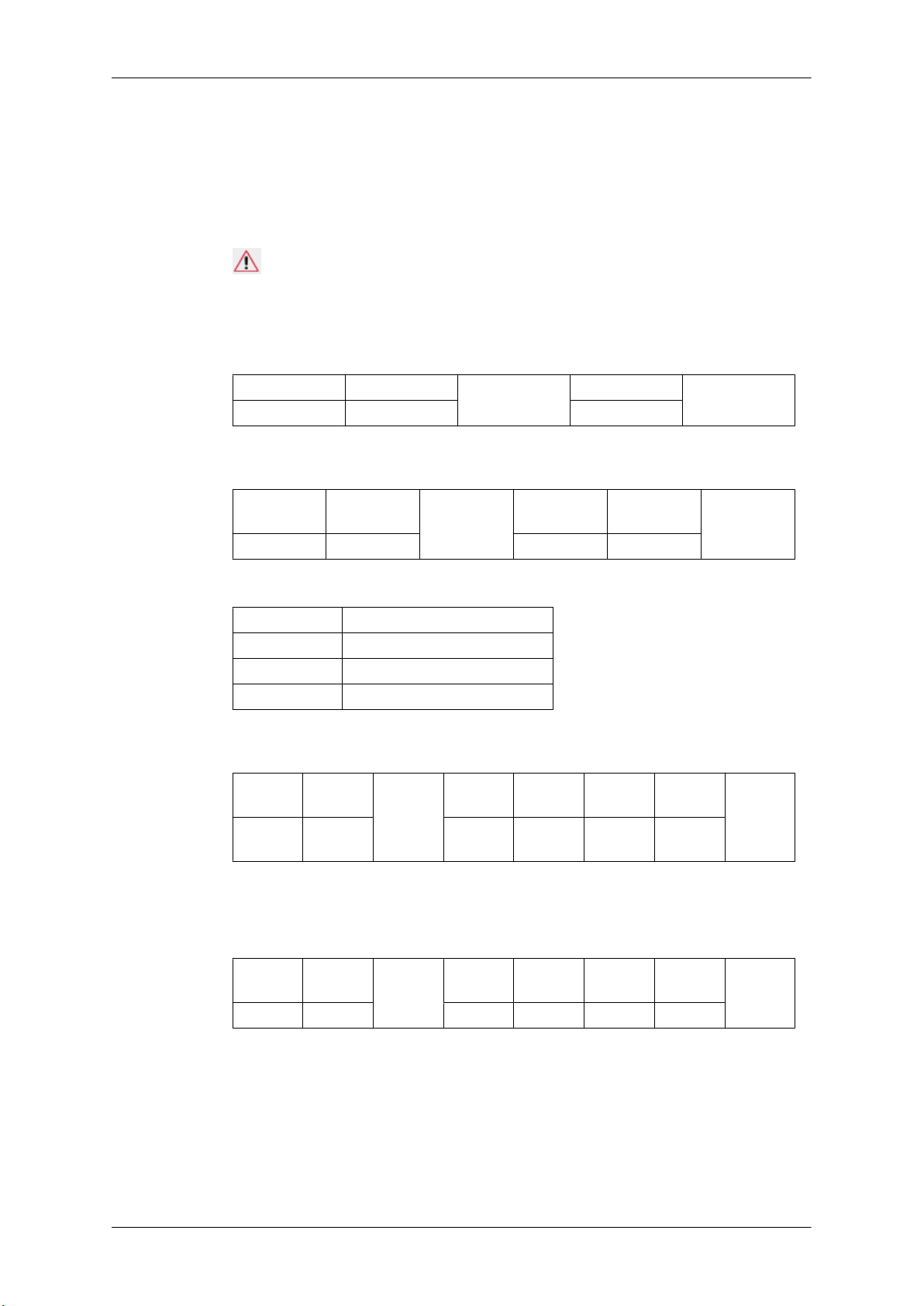
• Screen Mode Control
• Function
Personal Computer changes "Screen Mode" of TV / Monitor
Cannot be controlled when Video Wall is on.
Caution
Only works with models include TV.
• Get Screen Mode Status
Introduction
Header
0xAA 0x18 0
• Set Picture Size
Header command
0xAA 0x18 1 Screen Mode
Screen Mode : Screen Mode code to be set on TV / Monitor
0x01
0x04 Zoom
0x31 Wide Zoom
0x0B 4 : 3
• Ack
Header command
0xAA 0xFF 3 ‘A’ 0x18
16 : 9
command
ID
ID
DATA
Length
ID
DATA
Length
Ack/Nak r-CMD Val1
DATA Length
DATA
Screen
Mode
CheckSum
CheckSum
Check
Sum
Screen Mode : Same as above
• Nak
Header command
0xAA 0xFF 3 ‘N’ 0x18 ERR
ERR : Error code that shows what occurred error is
• Screen Size Control
• Function
Personal Computer recognizes the screen size of TV / Monitor.
ID
DATA
Length
Ack/Nak r-CMD Val1
Check
Sum
Page 32
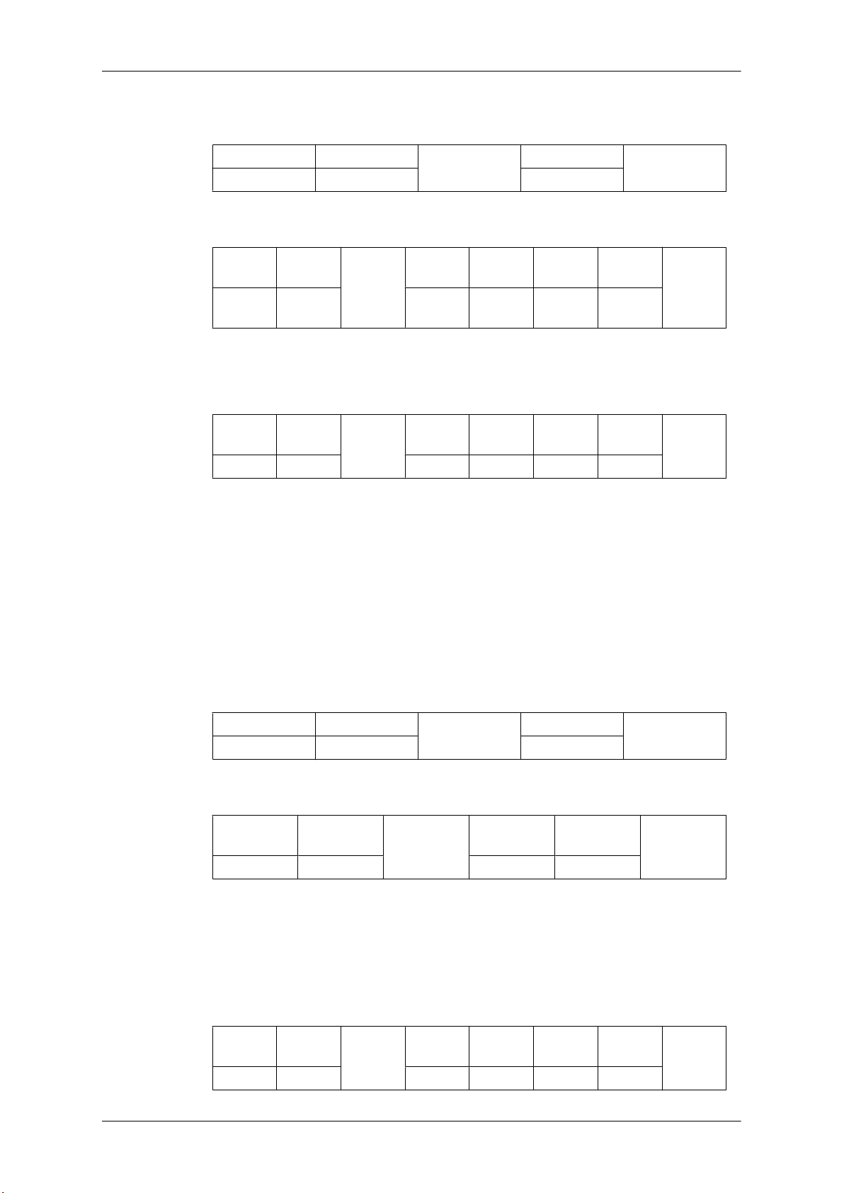
• Get Screen Size Status
Introduction
Header command
0xAA 0x19 0
• Ack
Header command
0xAA 0xFF 3 ‘A’ 0x19
Screen Size : Screen Size of TV / Monitor (Range : 0 ~ 255, Unit : Inch)
• Nak
Header command
0xAA 0xFF 3 ‘N’ 0x19 ERR
ERR : Error code that shows what occurred error is
• PIP ON / OFF Control
ID
ID
DATA
Length
DATA
Length
ID
DATA Length
Ack/Nak r-CMD Val1
Ack/Nak r-CMD Val1
Screen
Size
CheckSum
Check
Sum
Check
Sum
• Function
The PC turns the PIP function of a TV or Monitor ON / OFF.
This does not operate in MagicInfo mode.
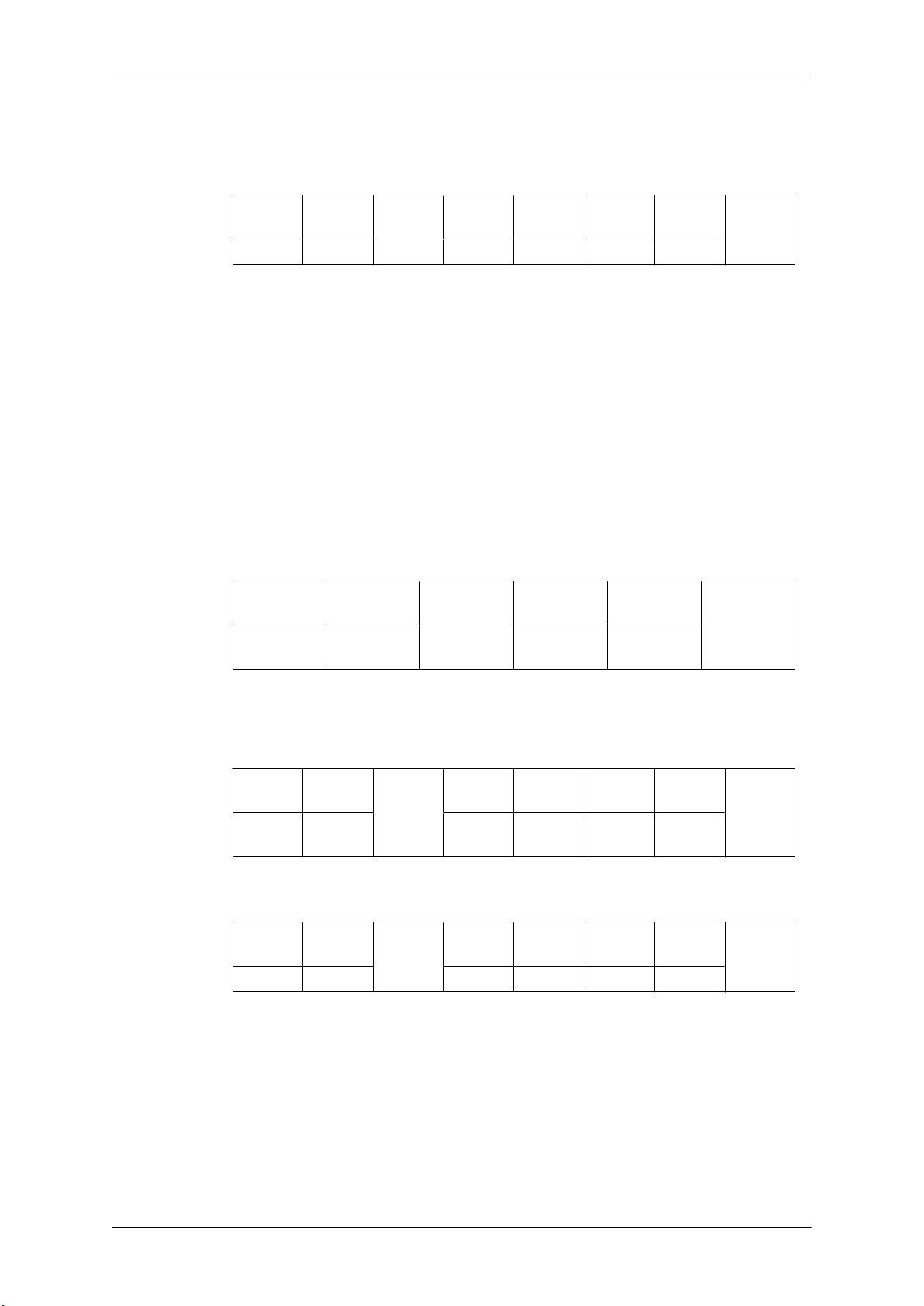
• Get the PIP ON / OFF Status
Header
0xAA 0x3C 0
• Set the PIP ON / OFF
Header command
0xAA 0x3C 1 PIP
PIP : The PIP ON / OFF code to set for the TV or Monitor
1 : PIP ON
0 : PIP OFF
command
ID
ID
DATA
Length
DATA Length
CheckSum
DATA
CheckSum
•
Ack
Header command
ID
0xAA 0xFF 3 ‘A’ 0x3C PIP
DATA
Length
Ack/Nak r-CMD Val1
Check
Sum
Page 33
PIP : Same as above
• Nak
Introduction
Header command
0xAA 0xFF 3 ‘N’ 0x3C ERR
ERR : Error code that shows what occurred error is
• Auto Adjustment Control (PC, BNC Only)
• Function
Personal Computer controls PC system screen automatically.
• Get Auto Adjustment Status
None
Set Auto Adjustment
•
Header
0xAA 0x3D 1 Auto Adjust-
command
ID
DATA
Length
ID
Ack/Nak r-CMD Val1
DATA
Length
DATA
ment
Check
Sum
CheckSum
Auto Adjustment : 0x00 (Always)
•
Ack
Header
0xAA 0xFF 3 ‘A’ 0x3D
• Nak
Header command
0xAA 0xFF 3 ‘N’ 0x3D ERR
ERR : Error code that shows what occurred error is
• Video Wall Mode Control
• Function
command
ID
ID
DATA
Length
DATA
Length
Ack/Nak r-CMD Val1
Auto Ad-
justment
Ack/Nak r-CMD Val1
Check
Sum
Check
Sum
Personal Computer converts Video Wall Mode of TV / Monitor when Video Wall is ON.
Only works with TV / Monitor where Video Wall is on.
Page 34
Does not operate in MagicInfo
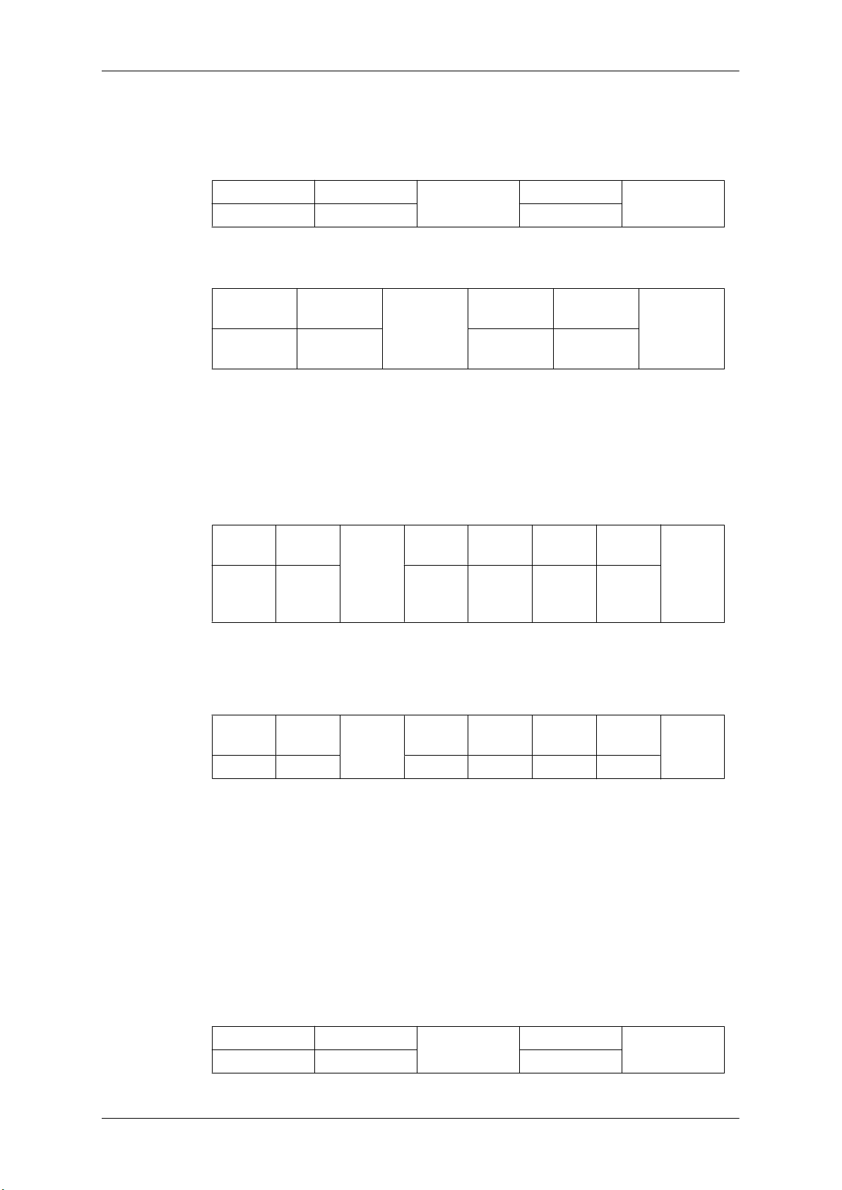
• Get Video Wall Mode
Introduction
Header
0xAA 0x5C 0
• Set Video Wall Mode
Header command
0xAA 0x5C 1 Video Wall
Video Wall Mode : Video Wall Mode code to be set on TV / Monitor
1 : Full
0 : Natural
• Ack
Header command
0xAA 0xFF 3 ‘A’ 0x5C
command
ID
ID
DATA
Length
ID
DATA Length
DATA
Length
Ack/Nak r-CMD Val1
DATA
Mode
Video
Wall
Mode
CheckSum
CheckSum
Check
Sum
Video Wall Mode : same as above
• Nak
Header
0xAA 0xFF 3 ‘N’ 0x5C ERR
ERR : Error code that shows what occurred error is
• Safety Lock
• Function
Personal Computer turns Safety Lock function of TV / Monitor ON / OFF.
Can operate regardless of whether power is ON / OFF.
• Get Safety Lock Status
command
Header
0xAA 0x5D 0
ID
command
DATA
Length
Ack/Nak r-CMD Val1
DATA Length
ID
Check
Sum
CheckSum
Page 35
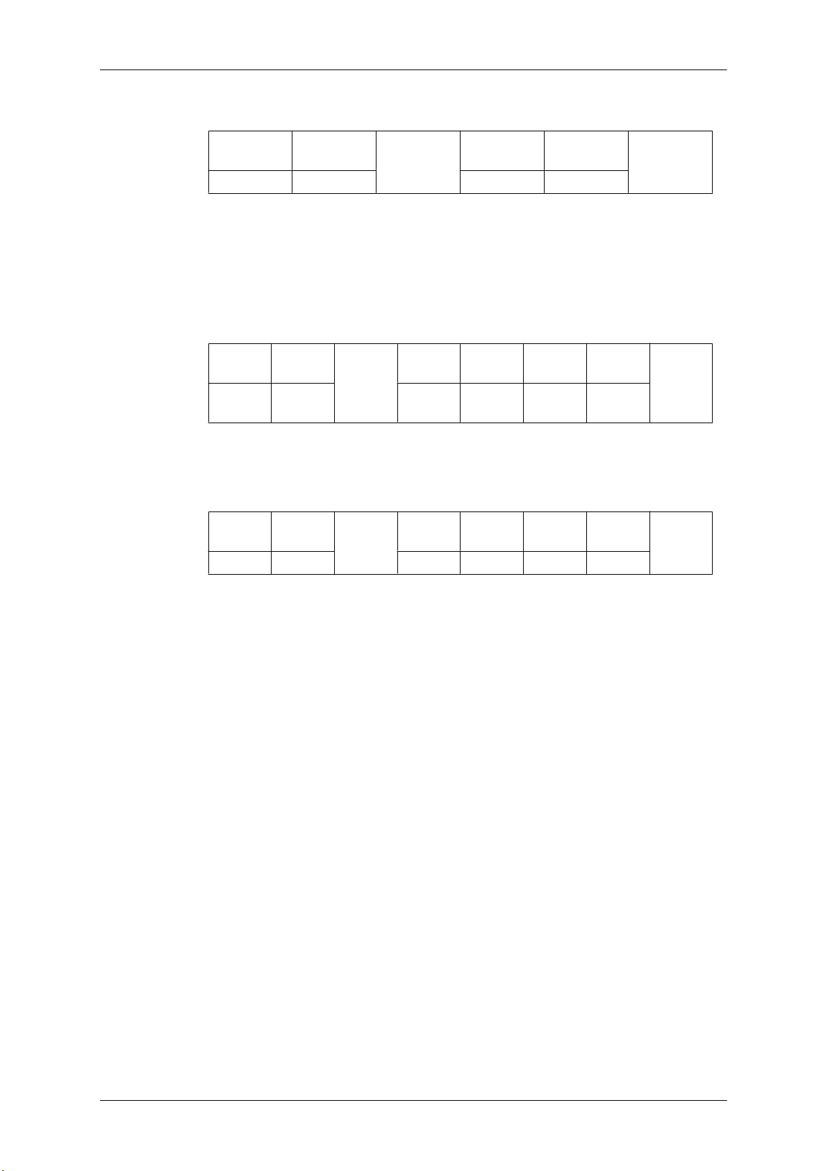
Introduction
• Set Safety Lock Enable / Disable
Header command
ID
0xAA 0x5D 1 Safety Lock
Safety Lock : Lock code to be set on TV / Monitor
1 : ON
0 : OFF
• Ack
Header command
ID
0xAA 0xFF 3 ‘A’ 0x5D
Safety Lock : Same as above
• Nak
Header command
ID
0xAA 0xFF 3 ‘N’ 0x5D ERR
DATA
Length
DATA
Length
DATA
Length
Ack/Nak r-CMD Val1
Ack/Nak r-CMD Val1
DATA
Safety
Lock
CheckSum
Check
Sum
Check
Sum
ERR : Error code that shows what occurred error is
Page 36
Connections
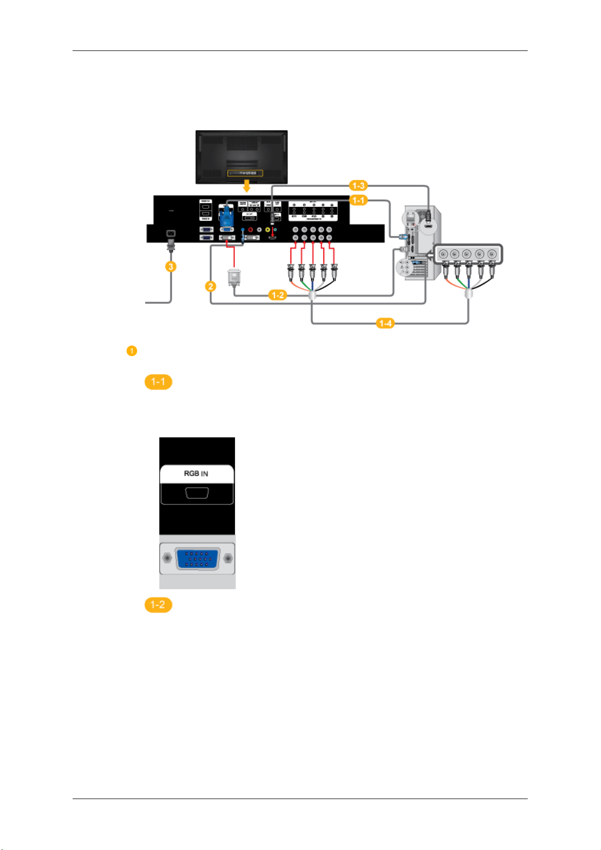
Connecting a Computer
There are several ways to connect the computer to the monitor. Choose one from
the following options.
Using the D-sub (Analog) connector on the video card.
• Connect the D-sub to
Display and the 15 pin D-sub Port on the computer.
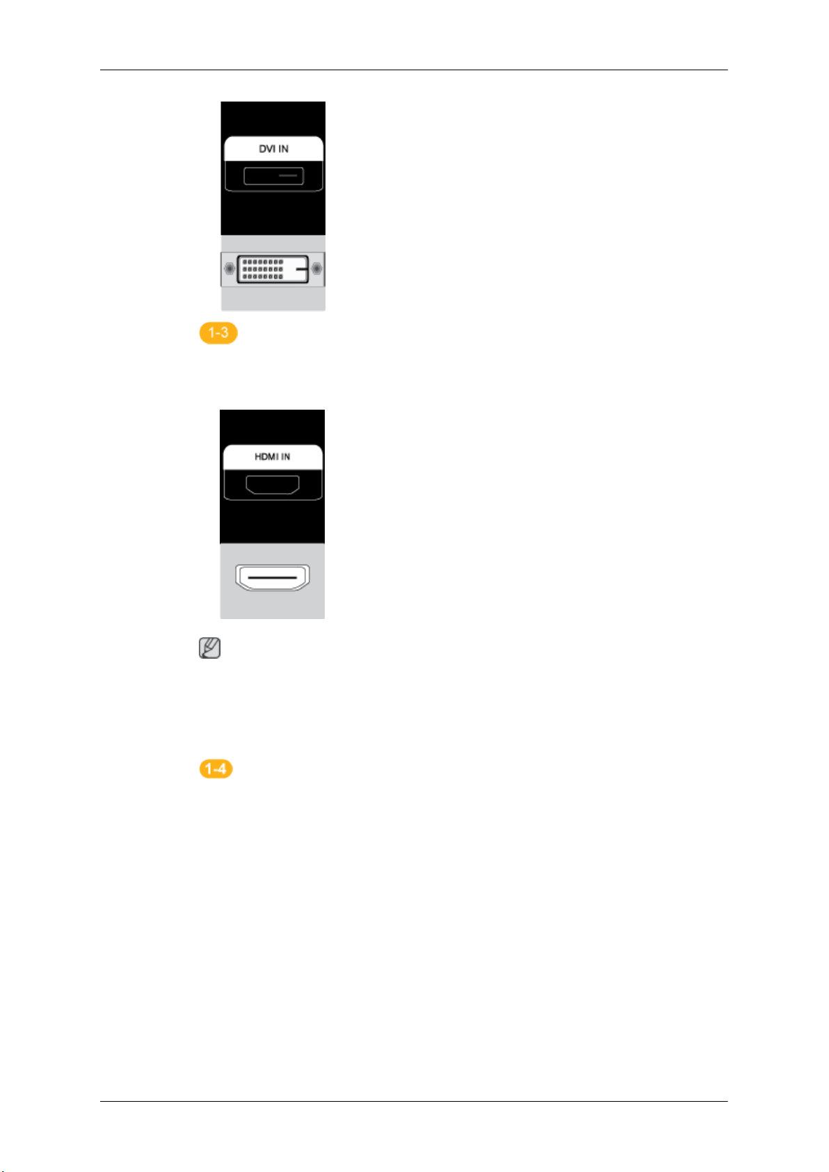
Using the DVI (Digital) connector on the video card.
• Connect the DVI Cable
and the DVI port on the computer.
the 15-pin, [RGB IN] port on the back of your PDP
to the [DVI IN] port on the back of your PDP Display
Page 37
Connections
Using the HDMI (digital) output on the graphics card.
• Connect the [HDMI IN] port
using the HDMI cable.
Note
When the HDMI cable to the PC, ensure that you select HDMI from both the
Source List and Edit Name before selecting PC or DVI device so that normal
PC screen and sound can be outputted.
on the PDP Display to the HDMI port on the PC
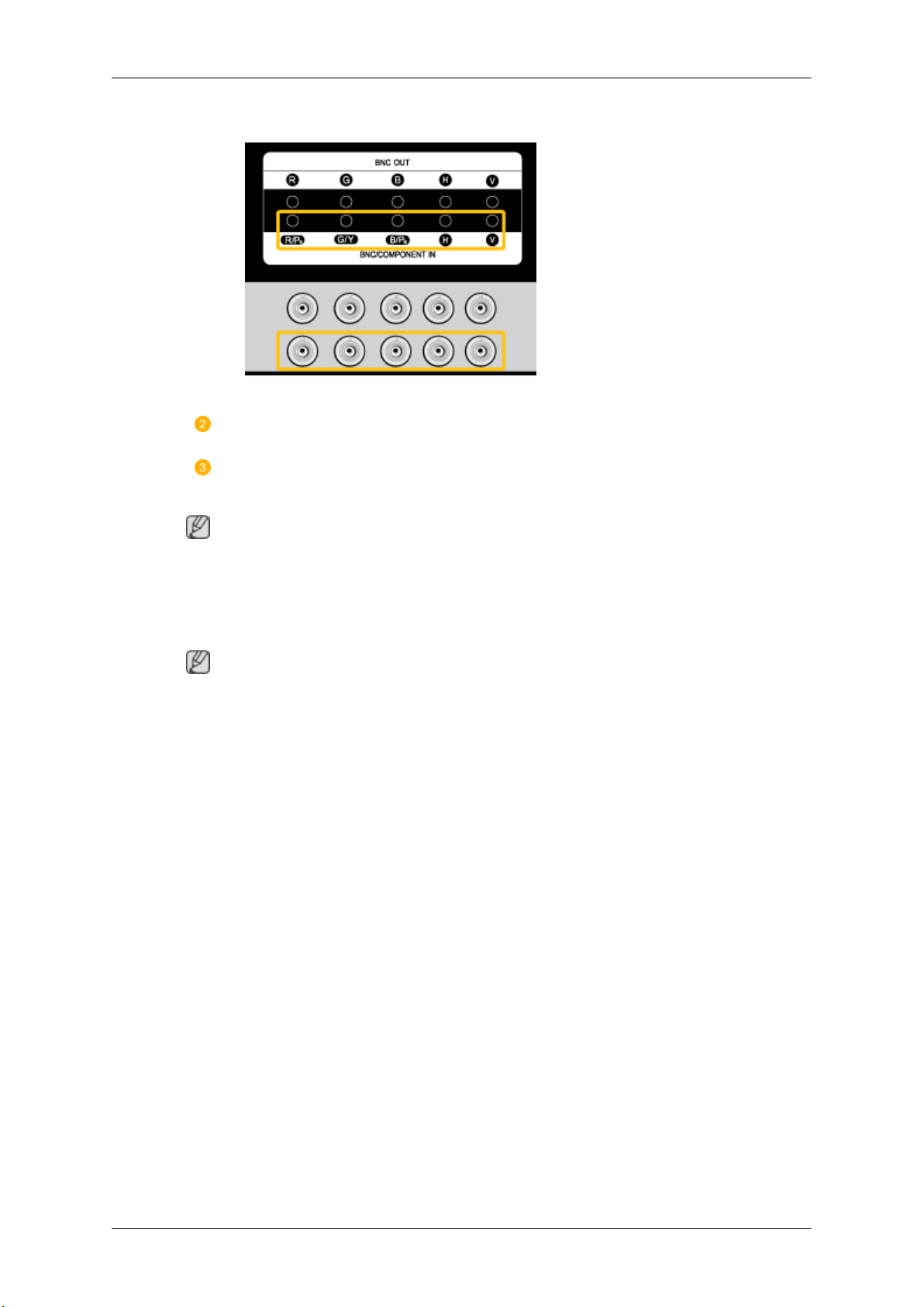
Using the BNC (Analog) connector on the video card.
• Connect the [BNC/COMPONENT IN] port
on the PC using the BNC to BNC cable.
on the monitor to the BNC port
Page 38
Connections
Connect the audio cable for your PDP Display to the audio port on the back of the
PDP Display.
Connect the power cord for your PDP Display to the power port on the back of
the PDP Display. .
Note
• Turn on both your computer and the PDP Display.
• Contact a local SAMSUNG Electronics Service Center to buy optional items.
Using Whiteboard (P64FT Model Only)
Note
• Whiteboard does not support MagicInfo mode.
• A stylus pen may be subject to electromagnetic interference.
•
This wireless device is subject to electromagnetic interference. Do not use this device for a purpose
that may affect personal safety.
1. Connecting to a PC
To use Whiteboard, the product should first be connected to a PC.
Refer to "Connecting a Computer" for details about how to connect the product to a PC.
Page 39
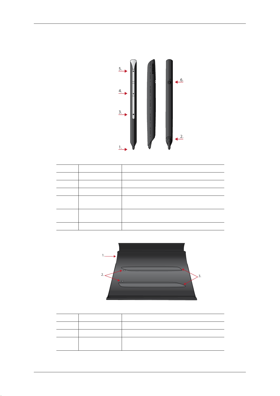
2. Components and Their Functions
2-1. Stylus pen
Connections
No. Parts Functions
1 Pen tip Enables the stylus pen when the sensor on it is pressed.
2 IR sensor Receives IR signals from the panel.
3 SW1 Performs the right-click command.
4 SW2 Functions as the Page Down key on the keyboard. An-
5 SW3 Functions as the Page Up key on the keyboard. An-
6 SW4 power switch
2-2. Pen Battery Charger
other function can be assigned as required.
other function can be assigned as required.
No. Parts Functions
1 Power in Connects to the power cable via the adapter.
2 LED Shows the charging status.
3 Stylus pen holders Charge the batteries on the stylus pens mounted in
correct orientation.
Page 40
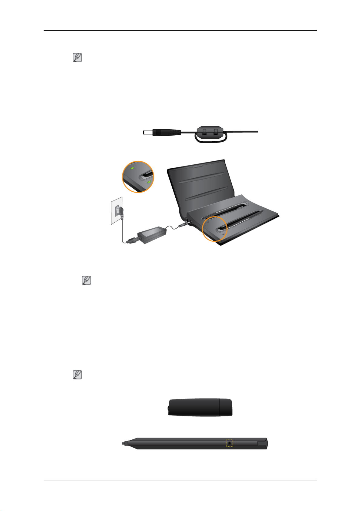
2-3 . Charging a Stylus Pen Battery
Note
• Apply a ferrite core when you charge a pen battery in the charger.
• It is recommended that you use a ferrite core when charging a stylus pen battery to avoid electromagnetic interference.
Connections
• Before
shown below.
• Red LED: Charging / Orange LED: Error / Green LED: Fully charged
you connect the cable, open the ferrite core and wrap the cable around the ferrite core as
Note
• If the LED remains
cannot power on, contact Samsung Customer Service Center.
• Charging a pen battery may fail unless the pen is mounted in correct orientation on the holder.
Connecting to a Stylus Pen
3-1. Attaching the Dongle
To use a dedicated stylus pen for Whiteboard, insert the dongle into the USB slot on your PC.
Note
• Ensure the dongle is installed 1m or higher from the ground.
3-2. Using a Stylus Pen
To use a stylus pen, press the black button at the upper part of the pen.
green when you charge a pen battery (indicating fully charged) but the pen
Page 41
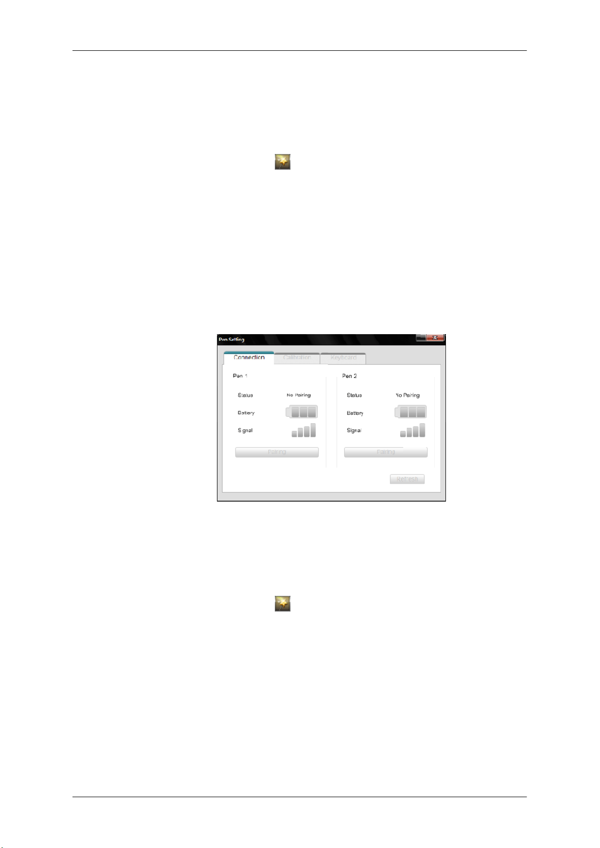
Connections
3-3. Pairing Stylus Pens with the Monitor
To connect dual pens
to "Installing Whiteboard" for details about how to install the drawing program.
• Go to Control Panel and run Samsung Interactive Whiteboard.
(Alternatively, click the star icon[
program.)
• Press and hold the (black) power button on the stylus pen for 10 seconds when the power button
is turned off.
• Powering on the pen: Press the black power button once. The red LED will blink several times
and the pen will power on.
• Powering off the pen: Press and hold the black power button for 3 seconds. The red LED will
blink several times and the pen will power off.
• Press Pairing in the Samsung Interactive Whiteboard program. If No Pairing changes to
Conneted, a pairing has been successfully performed and taps of the pen on the screen will immediately be recognized.
to the monitor, install the drawing program in the provided CD on the PC. Refer
] -> Pen Setting in the
bottom left corner of the drawing
• Pairing is required only once. After a pen is paired with the monitor, powering on the pen will
enable taps of the pen on the screen to be recognized.
3-4. Activating Calibration
• Go to Control Panel
(Alternatively, click the star icon[
program.)
• Go to the Calibration tab.
• Click Start Calibration.
• Tap the four circles in sequence using the pen, following the instructions displayed.
and run Samsung Interactive Whiteboard.
] -> Pen Setting in the
bottom left corner of the drawing
Page 42
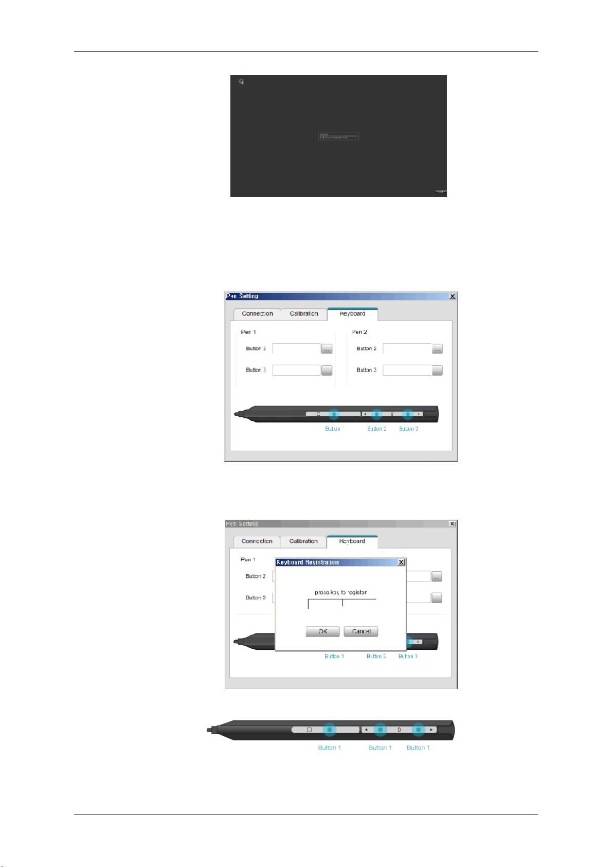
Connections
• Click OK.
3-5. Adding Keyboard Commands to Pens
Make better use of Whiteboard by adding keyboard commands to pens.
1. Go to Pen Setting >
2. Select a button. When the key assignment window appears, press the keyboard key you want to
assign. The key will be assigned to the button.
Keyboard in the Samsung Interactive Whiteboard program.
3-6. Right-click Function
Press Button 1 on the pen when the pen contacts the PDP screen. The right-click function of a mouse
will be performed.
Page 43
Note
• The right-click function does not work unless the pen contacts the PDP screen.
4. Afterimage Burn-in Prevention
Note
Connections
• Afterimages can occur on
not be liable for this issue.
• To prevent afterimages, it is recommended that you observe the following instructions when using
the product.
this product due to the nature of PDP devices and the manufacturer shall
Instructions
•
Ensure the same still image is not displayed for long hours.
• When you need to display the same still image for long hours, be sure to activate Screen saver
at regular intervals.
• It is best to activate Screen saver when the Samsung Interactive Whiteboard is not in use.
• Using screen saver
Activating screen saver (when the Interactive Whiteboard software is not
in use)
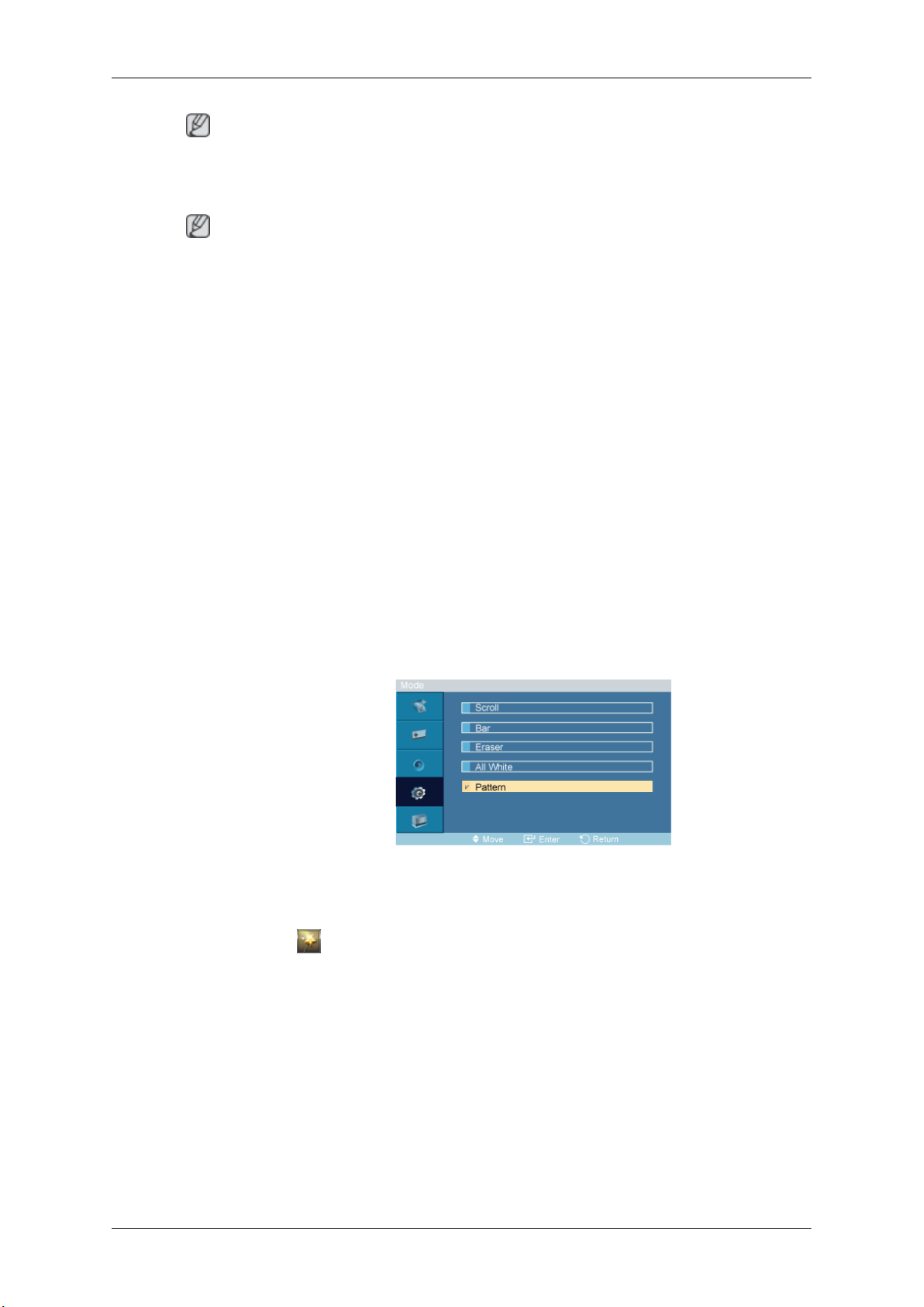
• Go to MENU -> Setup-> Safety Screen in the onscreen display menu and select Pattern mode. A screen saver pattern will activate.
Activating screen saver (when the Interactive Whiteboard software is in
use)
•
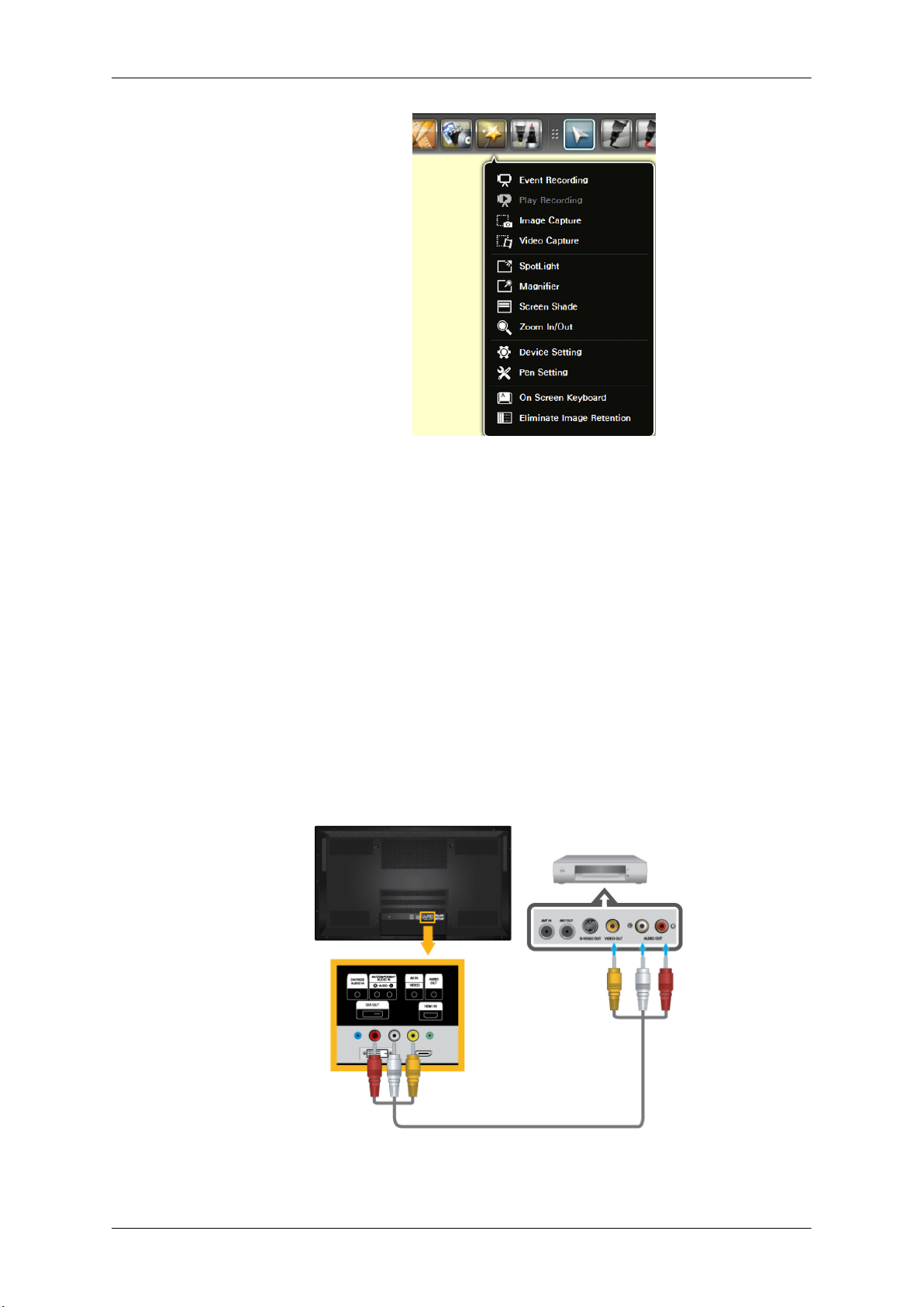
Click [ ] and select Eliminate
Whiteboard. A screen saver pattern will be activated.
Image
Retention
in the Interactive Samsung Interactive
Page 44
Connections
It is recommended that you activate screen saver for a short period of time
before you power off the PC.
• Activation of Screen saver after the interactive whiteboard program is closed
• If the
• If the PC is not turned off: The interactive whiteboard program will be closed only.
PC is turned off: Screen saver will be active for a specified time before the PC
powers of
Connecting to Other devices
• AV input devices such as DVD players, VCRs or camcorders as well as your computer can be
connected to the PDP Display. For detailed information on connecting AV input devices, refer to
the contents under Adjusting Your PDP Display.
• The PDP Display's configuration at the back may vary slightly depending on the PDP Display
model.
Connecting AV Devices
Page 45
Connections
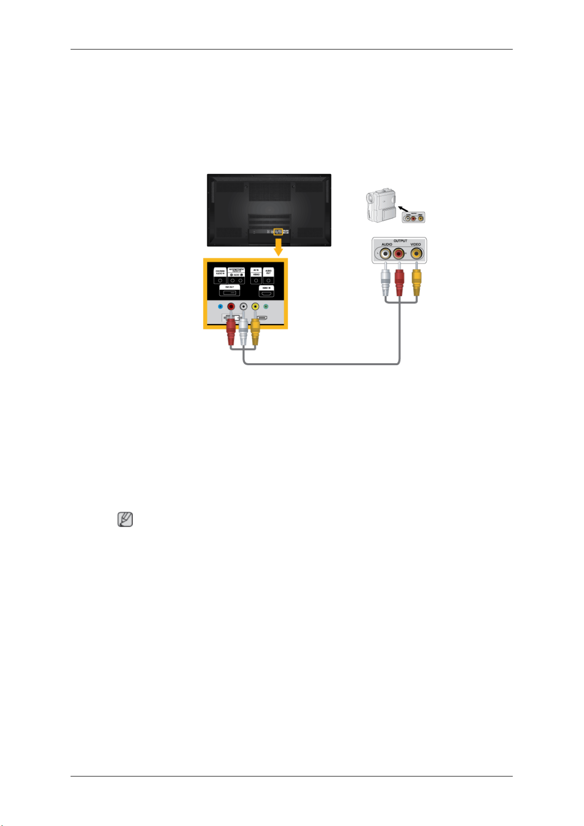
1. Connect an audio cable
AUDIO IN[R-AUDIO-L]] port on the monitor, and connect the video output port on the external
device to the [AV IN [VIDEO]] port on the monitor.
2. Play the DVD, VCR or Camcorder with a DVD disc or tape inserted.
3. Select AV using the SOURCE button on the front of the PDP display or on the remote.
Connecting to a Camcorder
to the audio output port on the external device and [AV/COMPONENT
1. Locate the AV output jacks on the camcorder. They are usually found on the side or back of the
camcorder. Connect a
and the [AV/COMPONENT AUDIO IN [R-AUDIO-L]] on the PDP Display .
2. Connect a video cable between the VIDEO OUTPUT jack on the camcorder and the [AV IN
[VIDEO]] on the PDP Display .
3. Select AV for the Camcorder connection using the SOURCE button on the front of the PDP
Display or on the remote control.
4. Then, start the Camcorder with a tape inserted.
Note
The audio-video cables shown
electronics store.)
If your camcorder is stereo, you need to connect a set of two cables.
set of audio cables between the AUDIO OUTPUT jacks on the camcorder
here are usually included with a Camcorder. (If not, check your local
Page 46
Connecting the BNC to BNC cable
Connections
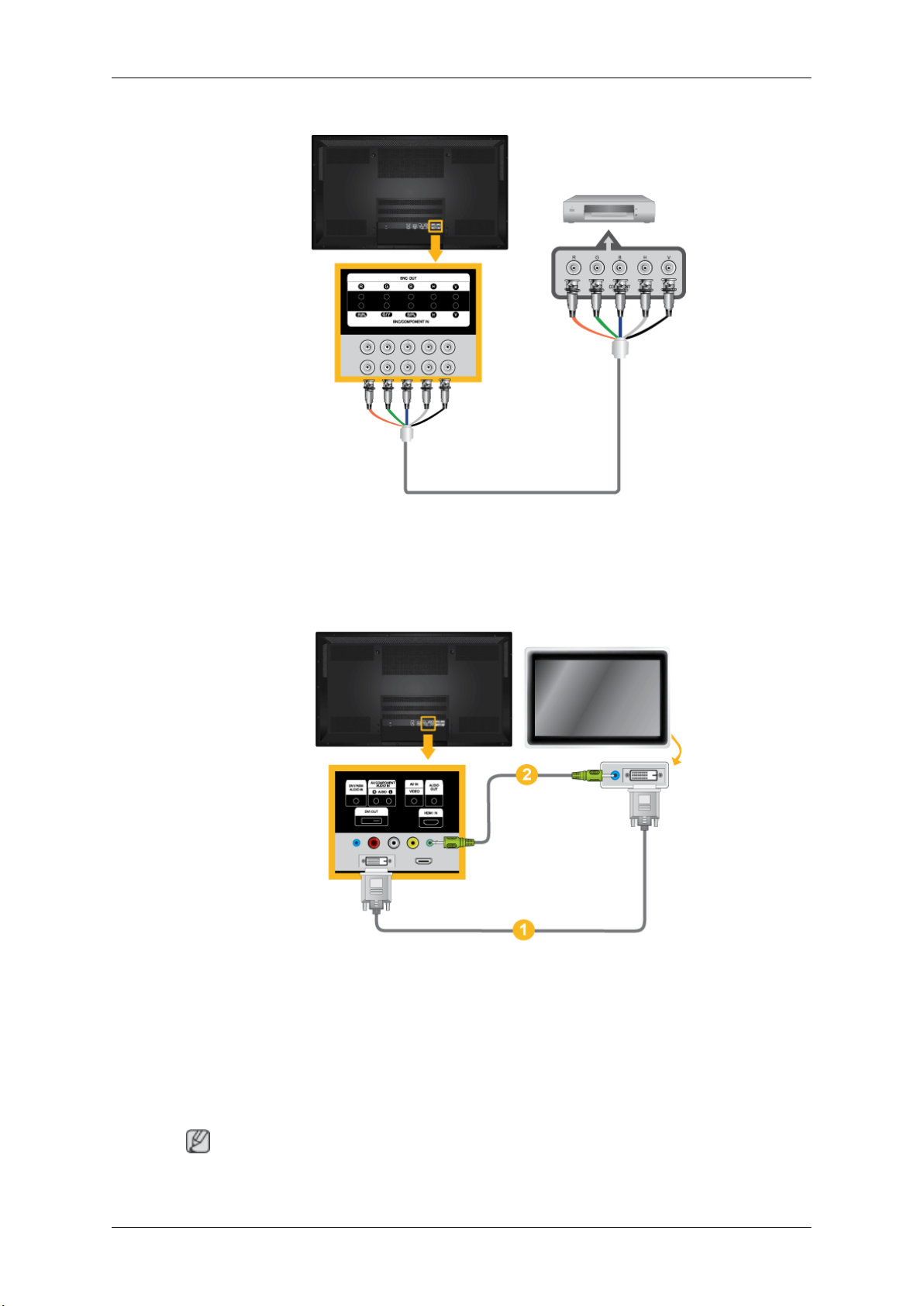
1. Connect the [BNC/COMPONENT IN [R/PR, G/Y, B/PB]] ports on the monitor to the BNC port
on the external device using the BNC to BNC cable.
2. Select BNC using the
SOURCE button on the front of the PDP Display or on the remote control.
Connecting Using a DVI Cable
1. Connect between the [DVI
using a DVI cable.
2. Connect between the [AUDIO OUT] port on the PDP Display and the audio input port on another
monitor using a stereo cable.
3. Select DVI using the SOURCE button on the front of the PDP Display or on the remote control.
Note
[DVI OUT] does not support HDCP.
OUT] port on the PDP Display and the input port on another monitor
Page 47
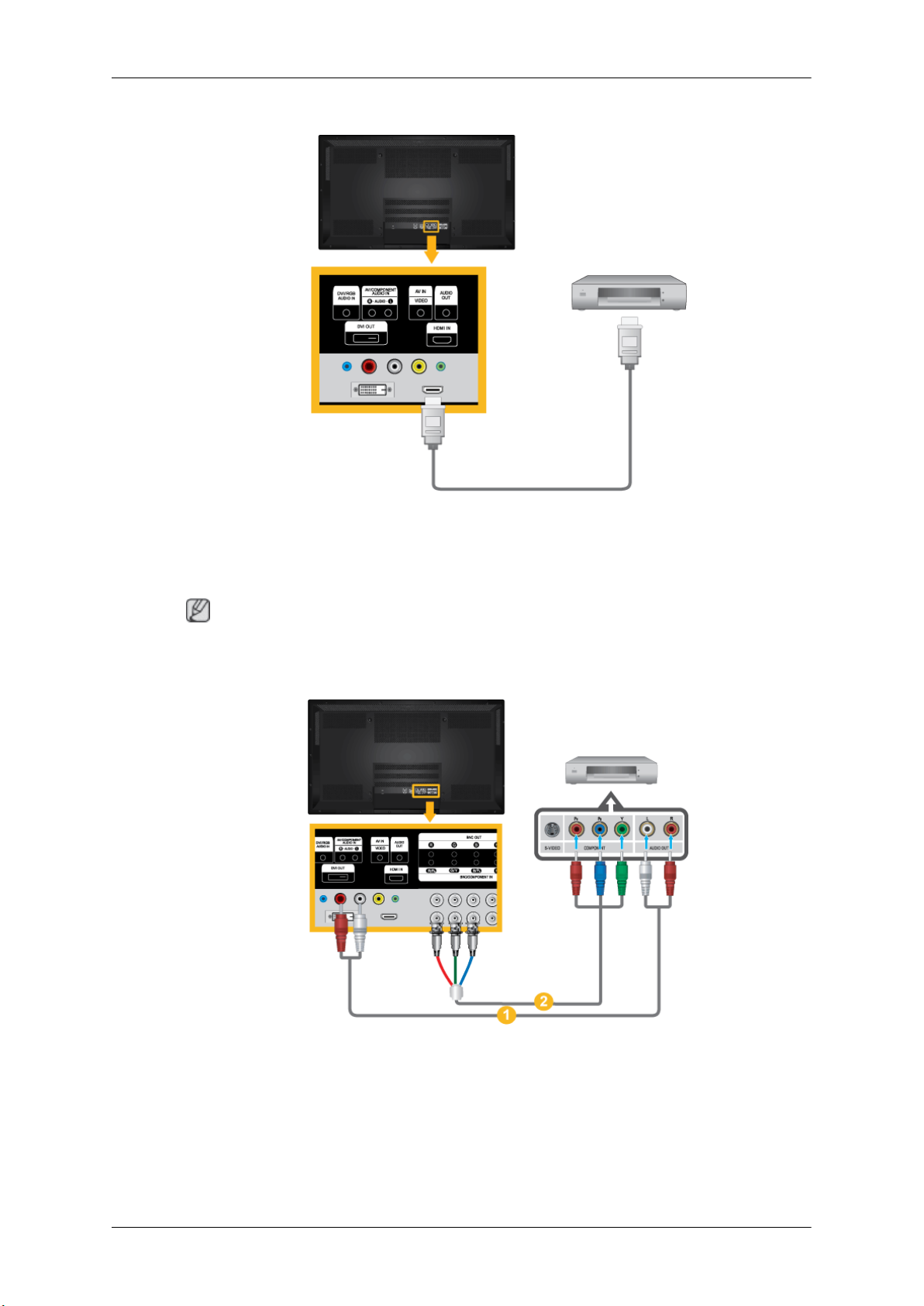
Connecting Using a HDMI Cable
Connections
1. Connect
Display using an HDMI cable.
2. Select HDMI using the SOURCE button on the front of the PDP Display or on the remote control.
Note
In HDMI mode, only PCM format audio is supported.
input
devices
Connecting a DVD Player
such
as a Blu-Ray/DVD player to the [HDMI IN] terminal of the PDP
1. Connect a set of audio cables between the [AV/COMPONENT AUDIO IN [R-AUDIO-L]] on
the PDP Display and the AUDIO OUT jacks on the DVD player.
2. Connect a Component cable between the [BNC/COMPONENT IN [R/PR, G/Y, B/PB]] port on
the PDP Display and the PR, Y, PB jacks on the DVD player.
Page 48
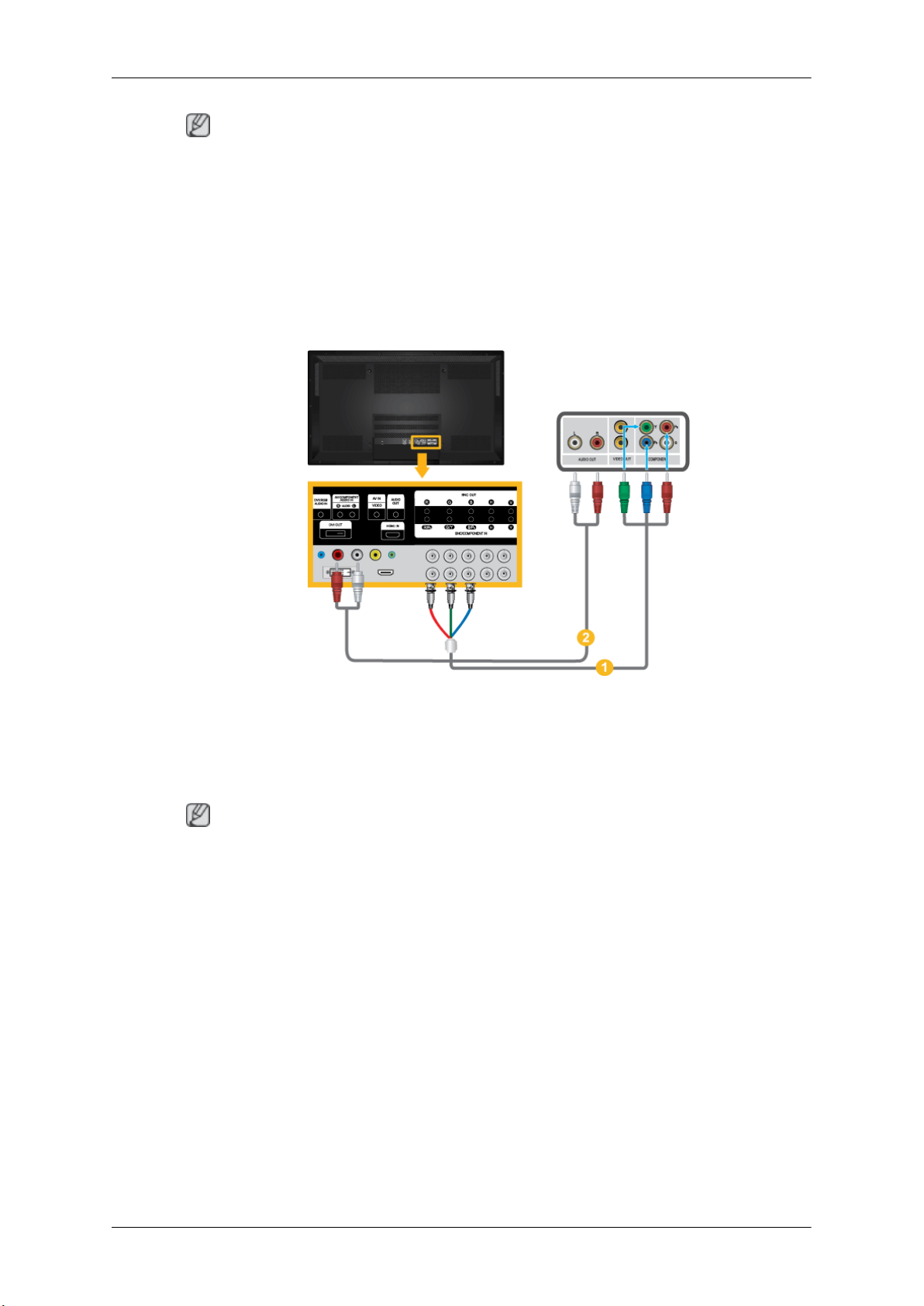
Note
Connections
• Select Component for
the PDP Display or on the remote control.
• Then, start the DVD Player with a DVD disc inserted.
• A component cable is optional.
• For an explanation of Component video, consult your DVD manual.
the connection to a DVD player using the SOURCE button on the front of
Connecting a DTV Set Top (Cable/Satellite) Box
1. Connect a Component cable
the PDP Display and the PR, Y, PB jacks on the Set Top Box.
2. Connect a set of audio cables between the [AV COMPONENT AUDIO IN [R-AUDIO-L]] on
the PDP Display and the AUDIO OUT jacks on the Set Top Box.
Note
• Select Component for the connection
front of the PDP Display or on the remote control.
• For an explanation of Component video, see your Set Top Box owner's manual.
between the [BNC/COMPONENT IN [R/PR, G/Y, B/PB]] port on
to a DTV Set Top Box using the SOURCE button on the
Page 49
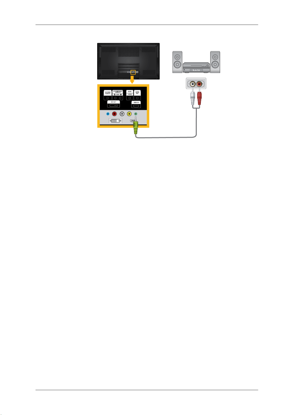
Connecting to an Audio System
Connections
1. Connect a set of
OUT] on PDP Display.
audio cables between the AUX L, R jacks on the AUDIO SYSTEM and [AUDIO
Page 50
Using the Software
Installing Whiteboard (P64FT Model Only)
1.
First, insert the Whiteboard installation CD into the CD-ROM drive.
Double-click Whiteboard.exe
2.
Click "Next" in the displayed installation wizard screen.
3.
4. When the "License Agreement" window appears, select "I accept the terms of the license
agreement" and click "Next."
5. Select "PC Mode" and click "Next" in the displayed "Setup Type" window.
6. Select "PDP Monitor" and click "Next."
7. Click "Install" in the displayed "Ready to Install the Program" window.
8. A window showing the installation progress will appear.
9. Click "Finish" in the displayed "InstallShield Wizard Complete" window.
10. After the installation, the Samsung Interactive Whiteboard shortcut icon will be created on the
desktop.
.
MDC (Multiple Display Control)
Installation
1. Insert the installation CD into the CD-ROM drive.
2. Click the Serial MDC installation program.
Note
If the screen for installing the software does not appear, install it using the Serial MDC execution
file in the MDC folder of the CD-ROM.
3. If the installation wizard screen does appear, click "Next."
4. The "License Agreement" screen will appear. Click "Yes."
5. The "Customer Information" window will appear. Register the user information and click "Yes."
6. The "Choose Destination Location" window will appear. Specify the file location to install to and
click "Next."
Note
If the file location is not specified, the program will be installed in the default file location.
7. The "Start Copying Files" window will appear. Confirm the file location and click "Next."
8. The installation progress screen will appear.
Page 51
Using the Software
9. The "InstallShield Wizard Complete" screen will appear. Click "Finish."
Note
Select " Launch Serial MDC" and click "Finish." The MDC program will immediately be run.
10. If the installation is
the desktop.
MDC execution icon may not appear depending on specification of computer system or
monitor. If that happens, press F5 Key.
Installation Problems
The installation of MDC
environment.
Uninstall
The MDC program can be removed only by using the "Add or Remove Programs" option of the
Windows® Control Panel.
Perform the following steps remove MDC.
Select "Setting/Control Panel" on the "Start" menu and then double-click "Add/Delete a program".
Select Serial MDC from the list and then click the "Add/Delete" button.
Using Serial MDC
successfully completed, the quick Serial MDC execution icon will appear on
can be affected by such factors as the video card, motherboard and the network
Page 52
Introduction
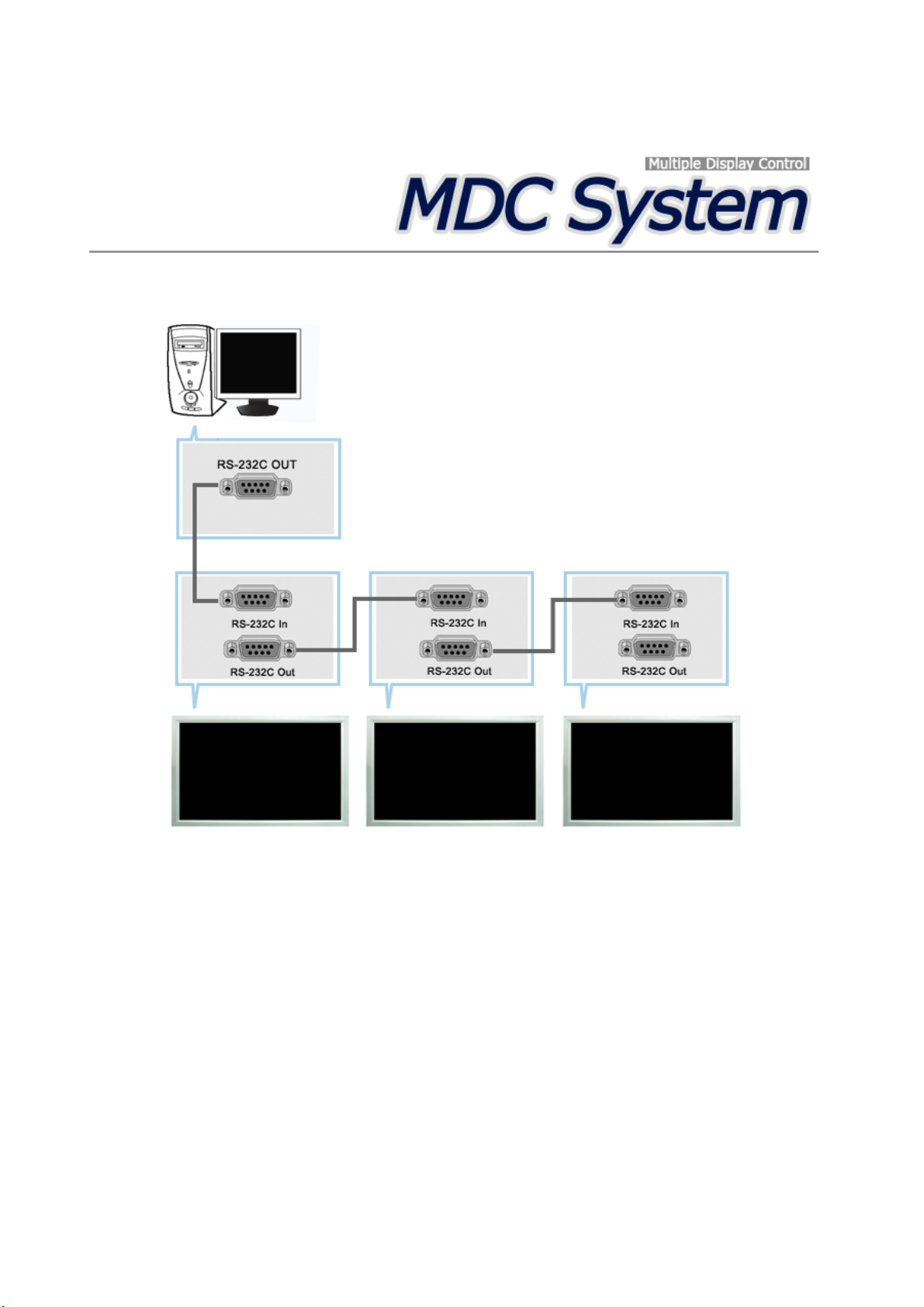
A Multiple Display Control (MDC) is an application allowing various displays to be easily and simultaneously
operated on a PC. RS-232C, a standard of serial communication, is used for the communication between a PC and
a display. Therefore, a serial cable should be connected between the serial port on a PC and the serial port on a
display.
Main Screen
Click Start > Program > Samsung > MDC System to start the program.
Select a set to see the volume of the selected set within the slider.
Page 53
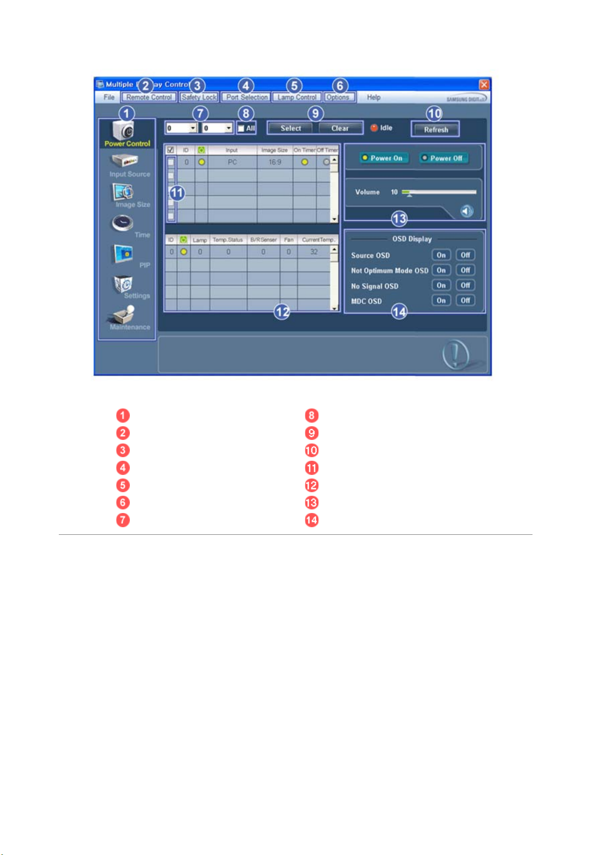
Main Icons All
Remote control Selection Buttons
Safety Lock Refresh
Port Selection Display Selection
Lamp Control Info Grid
Option... Control Tools
Dropdown Selectors OSD Display
1. Use the main icons to switch into each screen.
2. Allows you to enable or disable the remote control signal receiving function of the display unit.
3. Set the Safety Lock function.
When setting the Lock function, you can only operate power and lock buttons on the remote control and set.
4. The setting for the PC Serial Port can change. The original value is COM1.
5. Selects a Lamp adjustment mode.
6. Adjusts the number of LFD IDs and the frequency of search repeats.
7. Defines the range of LFD IDs to display. You can select or deselect the displayed IDs using the Select or Clear
button.
8. All of the monitors can be selected or deselected.
9. Selects (Select) or deselects (Clear) LFD IDs displayed by configuring 7 and 8.
10. This searches for monitors. The maximum number is indicated in the Max LFD Id field.
11. Select a display from Display Selection.
12. Use Grid to view brief information on selected display.
13. Use Control Tools to control displays.
Page 54
14. Switches the OSD function On/Off.
- May not be supported depending on the product.
<Note> The remote control Enable/Disable function operates whether or not the power is On/Off, and this
applies to all displays connected to the MDC. However, regardless of the status at the time the MDC is
shut down, the remote control signal receiving function of all displays is initialized to Enable when the
MDC is closed.
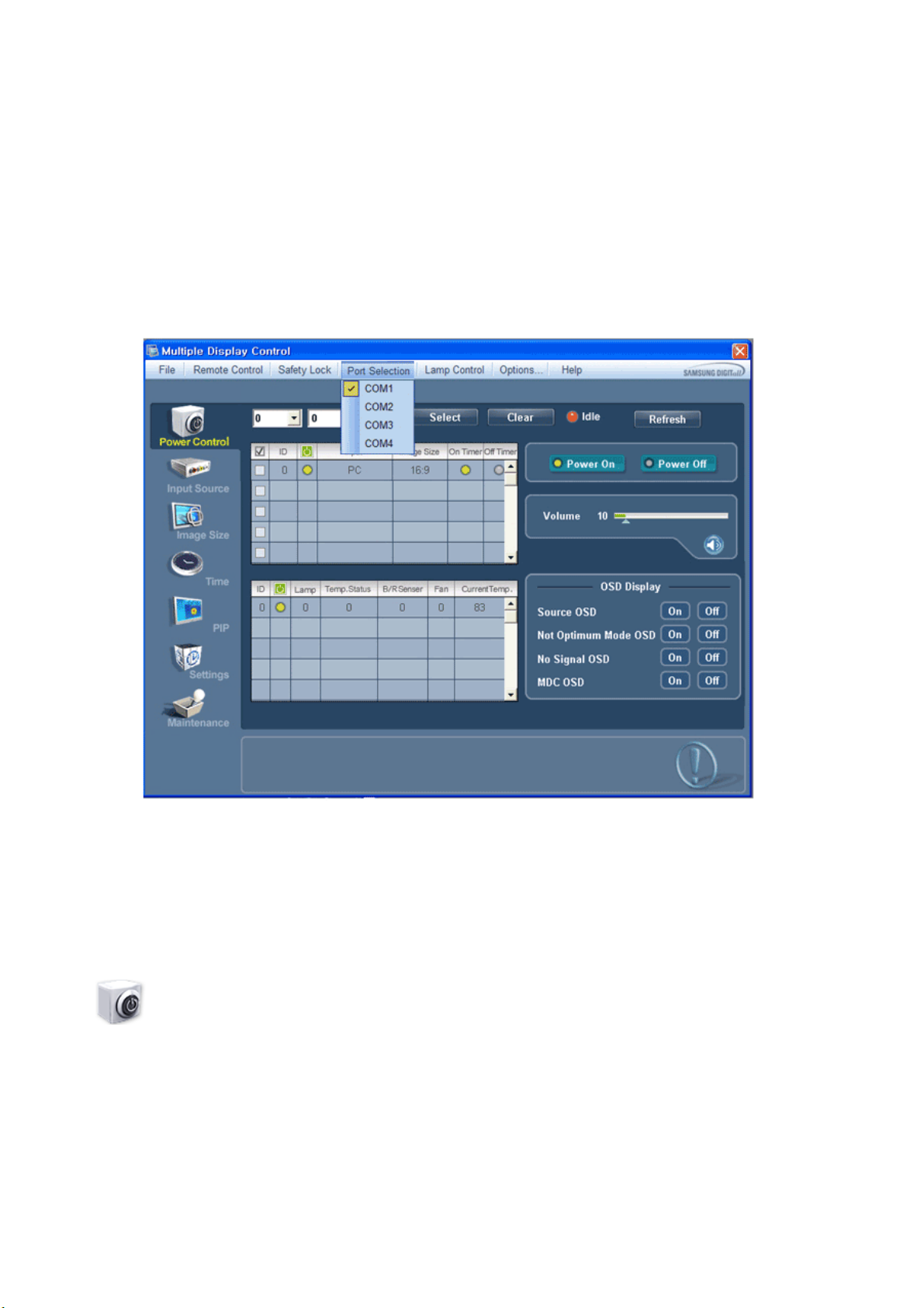
Port Selection
1. The Multiple Display Control is originally set to COM1.
2. If any port other than COM1 is used, COM1 through COM4 can be selected in the Port Selection Menu.
3. If the exact port name that is connected to the PDP Display using a serial cable is
be unavailable.
4. The se
lected port is stored in the program and used for the next program as well.
not selected, communication will
Power Control
1. Click Power Control of the main icons and the Power Control screen appears.
Page 55
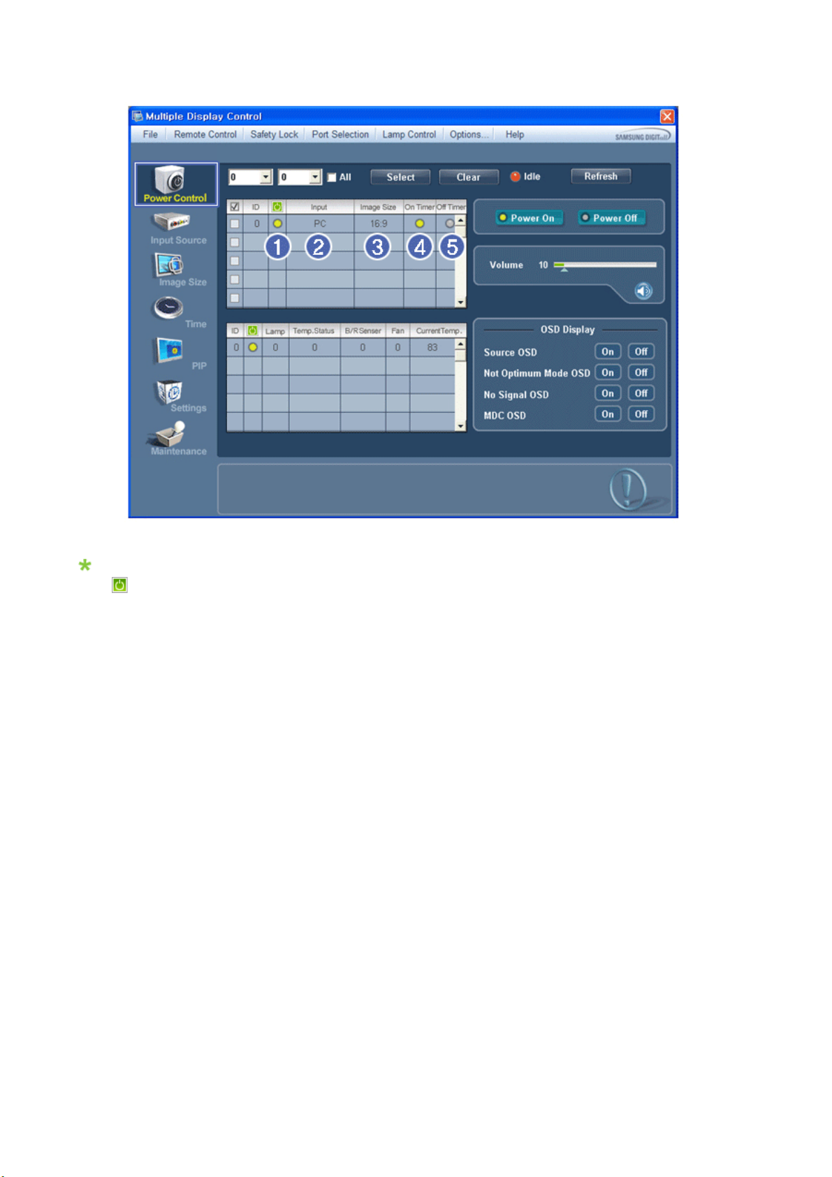
Info Grid shows some basic information necessary to Power Control.
1) (Power Status)
2) Input
3) Image Size
4) On Timer
5) Off Timer
2. Selects displays you want to adjust using the Select button or checkboxes.
Page 56
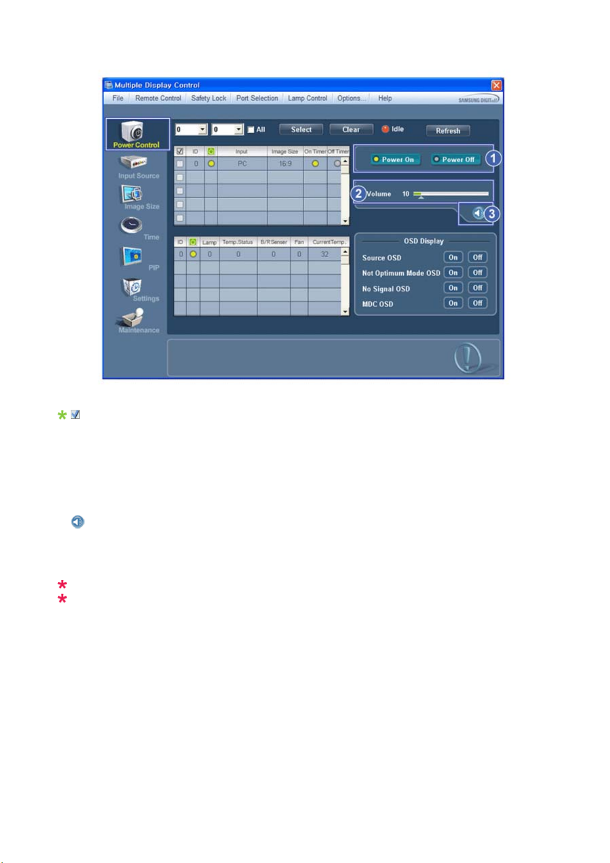
Power Control allows controlling some of the functions of the selected display.
T
g
1) Power On/Off
urns the power of the selected display On/Off.
-
2) Volume
- Controls the volume level of the selected display.
It receives the volume value of the selected display from the sets and displays it in the slider.
(If you deselect a single display or all displays, the default value 10 will be restored.)
3)
(Mute On/Off)
- Turns on/off the Mute function of the selected display.
When selecting one set at a time, turn on the Mute function for the selected set.
The Mute function is disabled automatically when you adjust the volume level.
(The values return to the default settin
s when you undo the selections or choose "Select All".)
The Power Control feature is available for all displays.
The Volume Control and Mute features are available only for the displays whose power status is ON.
3. Selects whether to display the menu screen using the OSD Display menu.
Page 57
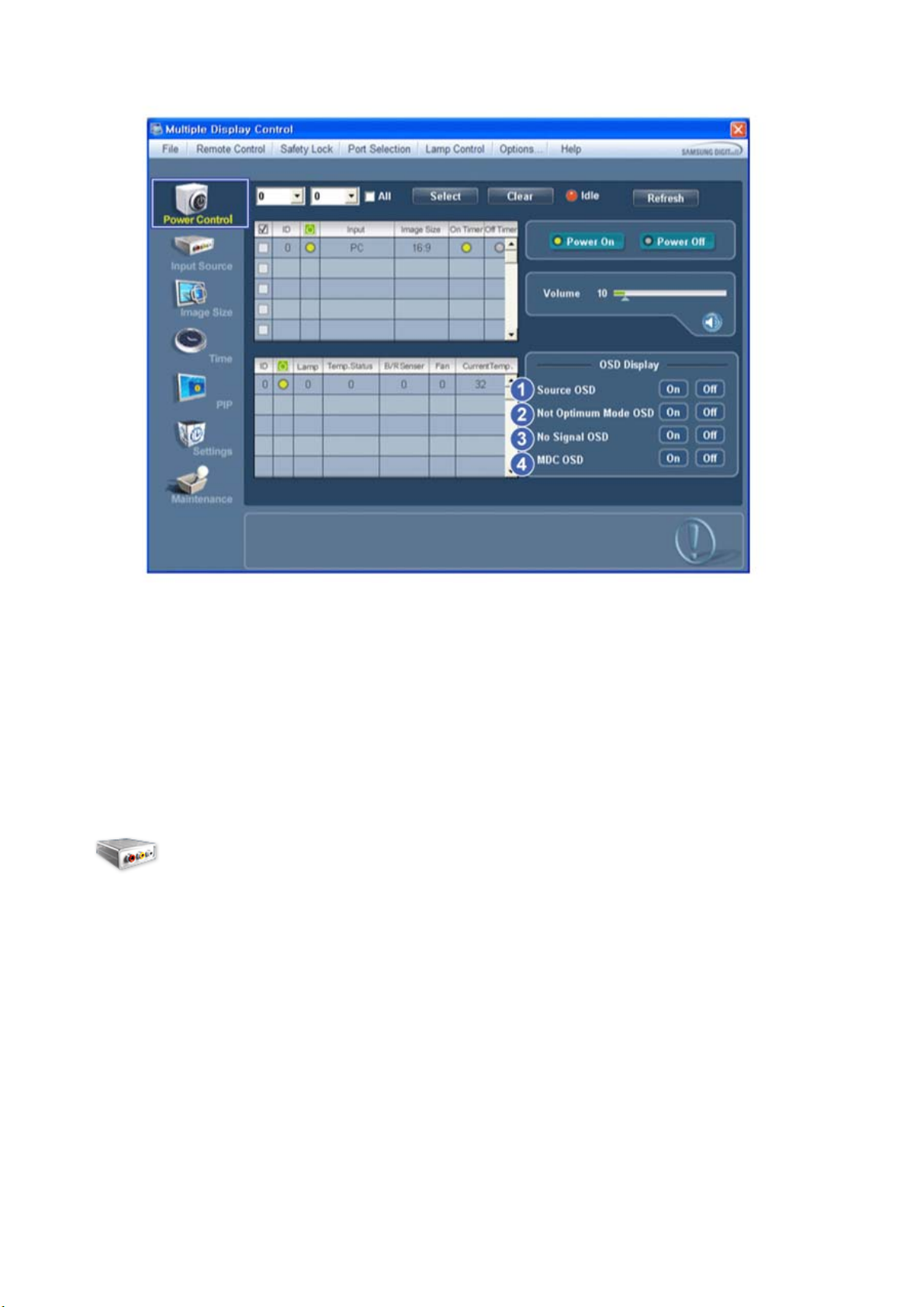
1) Source OSD
- Sets whether the Source OSD will be displayed to indicate when the Source is changed.
2) Not Optimum Mode OSD
- Sets whether the Optimum Mode OSD will be displayed to indicate if the current mode is not supported.
3) No Signal OSD
- Sets whether the No Signal OSD will be displayed to indicate when there is no signal.
4) MDC OSD
- Sets whether the MDC OSD will be displayed to indicate when the settings are changed using the MDC.
Input Source
1. Click Input Source of the main icons and the Input Source control screen appears.
Selects displays you want to adjust using the Select button or checkboxes.
• TV Mode
Page 58
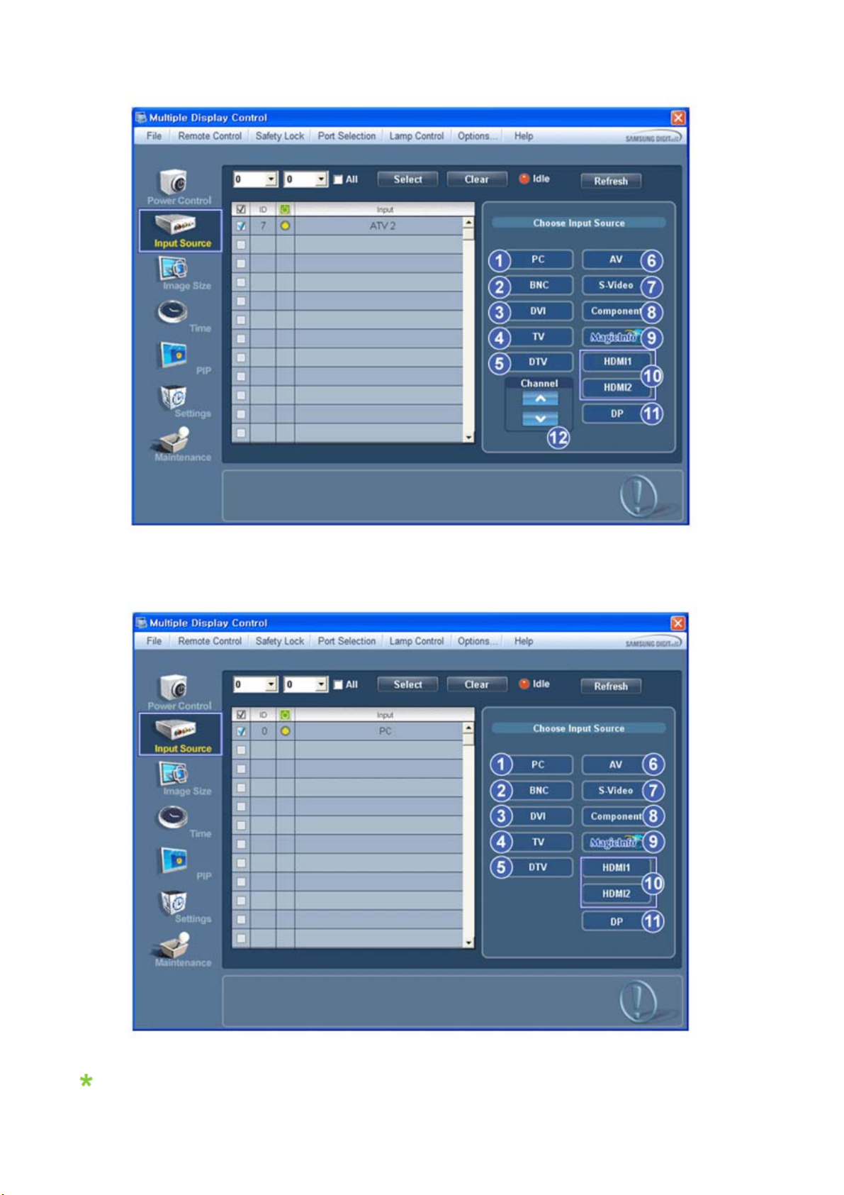
• PC Mode
Info Grid shows some basic information necessary to Input Source Control.
1)
PC
Page 59
- Changes the Input Source of the selected display to PC.
g
g
g
g
T
g
2) BNC
- Changes the Input Source of the selected display to BNC.
3) DVI
- Changes the Input Source of the selected display to DVI.
4) TV
-Chan
5) DTV
-Chan
6) AV
-Chan
7) S-Video
- Changes the Input Source of the selected display to S-Video.
8) Component
-Chan
9) MagicInfo
-
10) HDMI1/HDMI2
-Chan
11) DP
- Switches the input source for the selected Display to DP.
12) Channel
- Channel arrow appears when the Input Source is TV.
HDMI2 may not be supported depending on the product.
DP may not be supported depending on the product.
TV Source can be selected only in products with TV and controlling channels is allowed only when
Input Source is TV.
The Input Source Control feature is available only for the displays whose power status is ON.
es the Input Source of the selected display to TV.
es the Input Source of the selected display to DTV.
es the Input Source of the selected display to AV.
es the Input Source of the selected display to Component.
he Input source of MagicInfo works only on MagicInfo model.
es the Input Source of the selected display to HDMI.
Image Size
PC, BNC, DVI, DP
1. Click Image Size of the main icons and the Image Size control screen appears.
Page 60
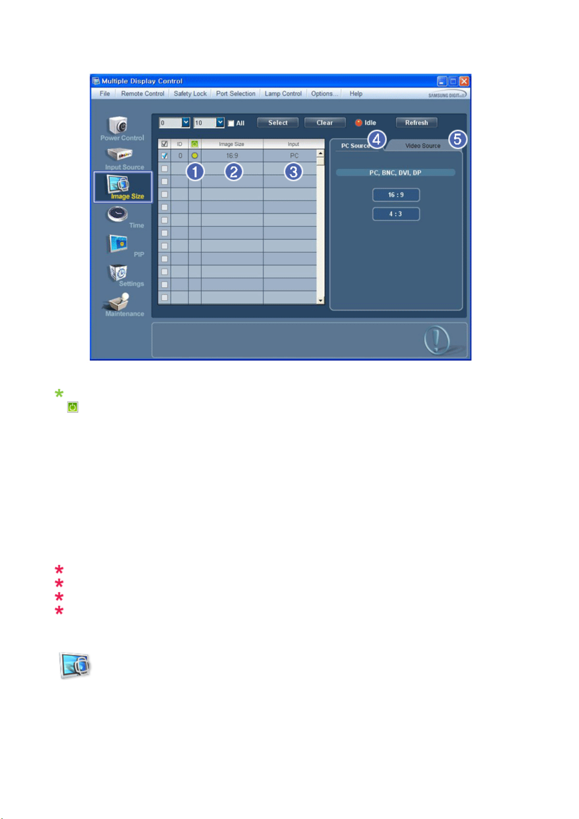
Info Grid shows some basic information necessary to Image Size Control.
1)
( Power Status)
- Shows the power status of the current display.
2) Image Size
- Shows the current Image Size of the display in use.
3) Input
- Info Grid displays only the displays whose Input Source is PC, BNC, DVI and DP.
4) PC Source
- Click Image Size in the main menu to display the PC, BNC, DVI and DP tabs.
- The Image Size Control button controls Image Size available for PC, BNC, DVI and DP.
5) Video Source
- Using the Image Size adjustment button, you can adjust the Image Size to a value available in the PC, BNC, DVI
and DP.
DP may not be supported depending on the product.
The Input source of MagicInfo works only on MagicInfo model.
The Input source of TV works only on TV model.
Image Size Control is available only for the displays for which power status is ON.
Image Size
TV, AV, S-Video, Component, DVI(HDCP), HDMI1, HDMI2, DTV.
1. Click Image Size of the main icons and the Image Size control screen appears.
Page 61
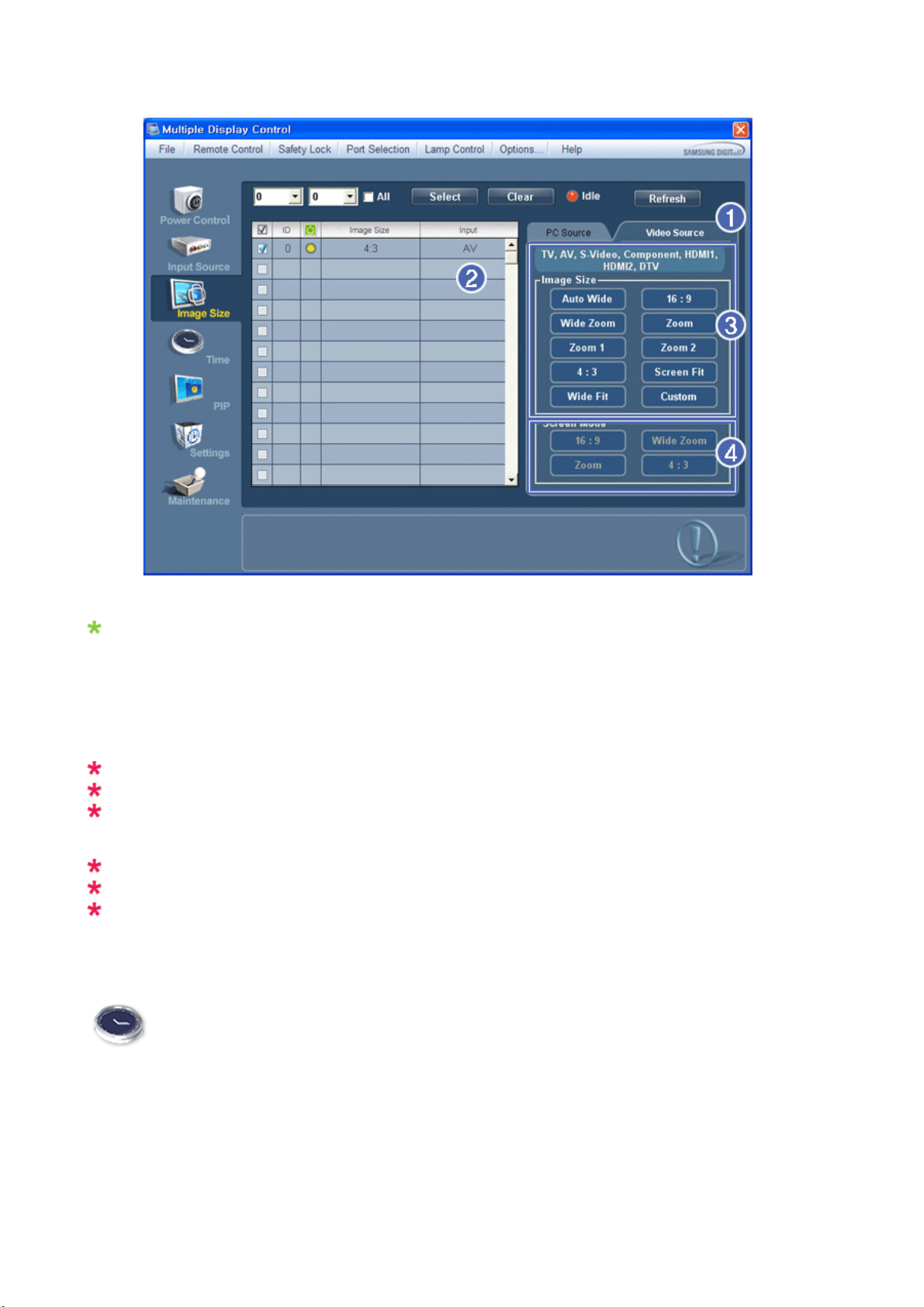
Info Grid shows some basic information necessary to Image Size Control.
1) To adjust Image Size in TV, AV, S-Video, Component, HDMI1, HDMI2 or DTV mode, click the Video Source tab.
Select the display you want to adjust by using the Select button or by checking the checkbox.
2) Info Grid displays only the display having TV, AV, S-Video, Component, HDMI1, HDMI2 or DTV as input source.
3) Switch Image Size of the selected display randomly.
4) The screen modes can only be adjusted when a TV (PAL only) is connected and the Image Size item is set to Auto
Wide.
HDMI2 may not be supported depending on the product.
Custom may not be supported depending on the product.
Auto Wide, Zoom1 and Zoom2 are not available for selection when the input signal type for Component
and DVI (HDCP) is 720p or 1080i.
(The Auto Wide mode is available only for TV, AV, and S-Video.)
The Input source of MagicInfo works only on MagicInfo model.
The Input source of TV works only on TV model.
The Image Size Control feature is available only for the displays whose power status is ON.
Time
1. Click Time of the main icons and the Time Control screen appears.
Page 62
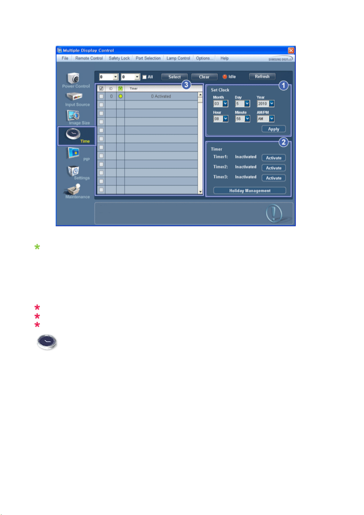
Info Grid shows some basic information necessary to Time Control.
1) Set clock
- Set the current time for the selected display (PC Time).
- To change the current time, first change the PC Time.
2) Timer
- Sets up Timer1, Timer2, Timer3 and Holiday Management.
3) Shows whether Timer is activated.
The Input source of MagicInfo works only on MagicInfo model.
The Input source of TV works only on TV model.
Time Control is available only for the displays for which the power status is ON.
Time
Setting up Timer and Holiday Management
1. 1. Setting up Timer1, Timer2 and Timer3
Page 63
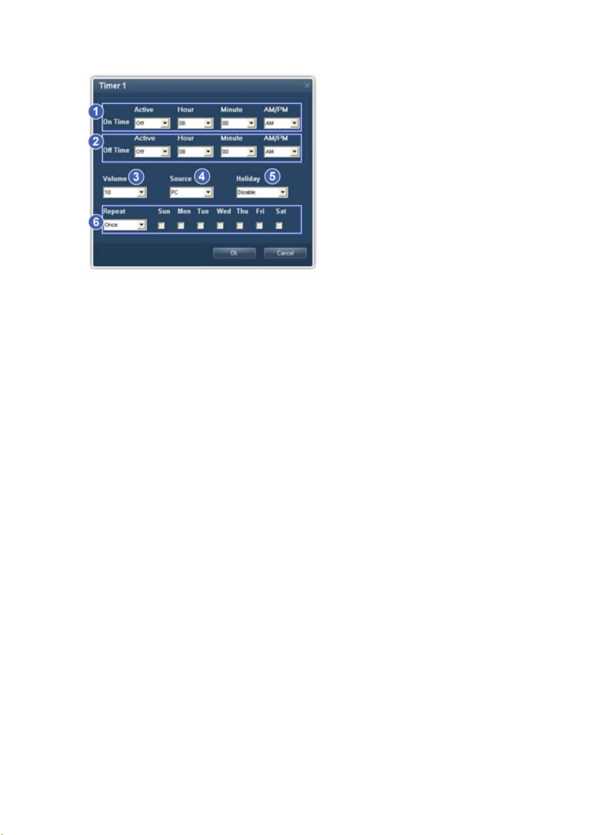
1) On Time
- Sets the time in hours, in minutes and as AM/PM for turning the selected monitor on.
2) Off Time
- Sets the time in hours, in minutes and as AM/PM for turning the selected monitor off.
3) Volume
- Selects the volume when the selected monitor is turned on.
4) Source
- Selects the external input source that will be displayed when the selected monitor is turned on.
5) Holiday
- Applies the Holiday Management function to the Timer.
6) Repeat
- Available selections include Once, EveryDay, Mon~Fri, Mon~Sat, Sat~Sun, and Manual.
z Once : The Timer goes off only once.
z EveryDay : EveryDay: The Timer repeats daily.
z Mon~Fri : The Timer repeats from Monday through Friday.
z Mon~Sat : The Timer repeats from Monday through Saturday.
z Sat~Sun : Sat~Sun: The Timer goes off on Saturday and Sunday.
z Manual : Select a day of the week you want the Timer to go off.
2. Setting Holiday Management
The Holiday Management function specifies the dates in which the monitor will not be turned on or off by the Timer.
Page 64
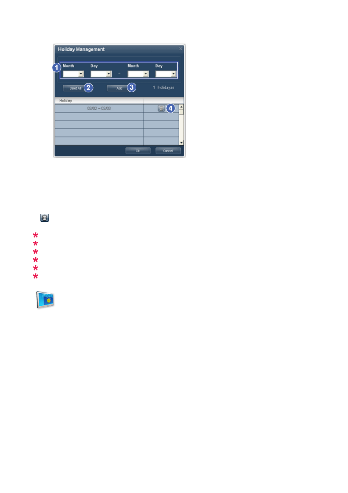
1) Specifies the date.
2) Delete All
- Deletes all of the holidays.
3) Add
- Adds the specified date.
4)
- Deletes the schedule in the selected line.
The Holiday Management function can be turned on or off in the Timer setup menu.
The Input source of MagicInfo works only on MagicInfo model.
The Input source of TV works only on TV model.
Time Control is available only for the displays for which the power status is ON.
Only enabled for a TV when Source is set to TV in On Time mode.
Only enabled for a model with MagicInfo installed when Source is set to MagicInfo in On Time mode.
PIP
PIP Size
1. Click PIP of the main icons and the PIP control screen appears.
Selects displays you want to adjust using the Select button or checkboxes.
Page 65
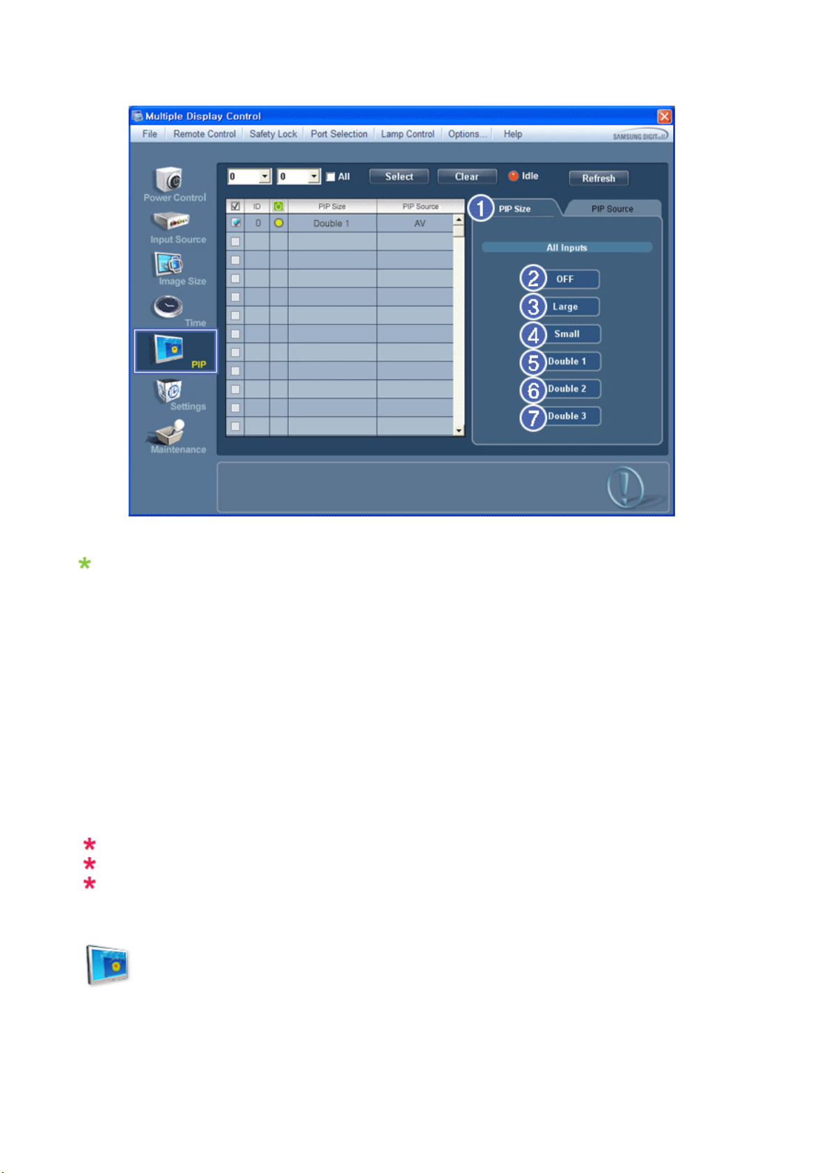
Info Grid shows some basic information necessary to PIP Size Control.
1) PIP Size
- Shows the current PIP Size of the display in use.
2) OFF
- Turns off the PIP of the selected display.
3) Large
- Turns on the PIP of the selected display and changes the size to Large.
4) Small
- Turns on the PIP of the selected display and changes the size to Small.
5) Double 1
- Turns on the PIP of the selected display and changes the size to Double 1.
6) Double 2
- Turns on the PIP of the selected display and changes the size to Double 2.
7) Double 3 (Picture By Picture)
- Turns on the PBP of the selected display and changes the size to Double 3.
The Input source of MagicInfo works only on MagicInfo model.
The Input source of TV works only on TV model.
PIP Size can be controlled with turning on the PDP Display power.
PIP
PIP Source
1. Click PIP of the main icons and the PIP control screen appears.
Page 66
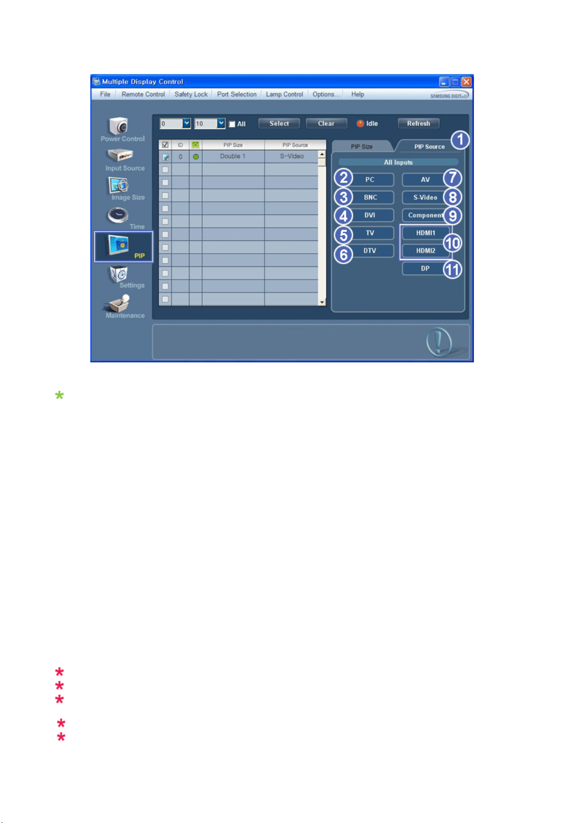
Info Grid shows some basic information necessary to PIP Source Control.
1) PIP Source
- PIP Source can be controlled with turning on the PDP Display power.
2) PC
- Changes the source of the PIP of the selected display to PC.
3) BNC
- Changes the source of the PIP of the selected display to BNC.
4) DVI
- Changes the source of the PIP of the selected display to DVI.
5) TV
- Changes the source of the PIP of the selected display to TV.
6) DTV
- Changes the source of the PIP of the selected display to DTV.
7) AV
- Changes the source of the PIP of the selected display to AV.
8) S-Video
- Changes the source of the PIP of the selected display to S-Video.
9) Component
- Changes the source of the PIP of the selected display to Component.
10) HDMI1/HDMI2
- Changes the source of the PIP of the selected display to HDMI.
11) DP
- Switches the PIP Source of the selected Display to DP.
HDMI2 may not be supported depending on the product.
DP may not be supported depending on the product.
Some of the PIP Sources may not be available for selection, depending on the input source type of the
Main Screen.
The Input source of MagicInfo works only on MagicInfo model.
The PIP Control feature is available only for the displays whose power status is ON and the PIP
function is set to ON.
Page 67
j
j
j
j
Settings
Picture
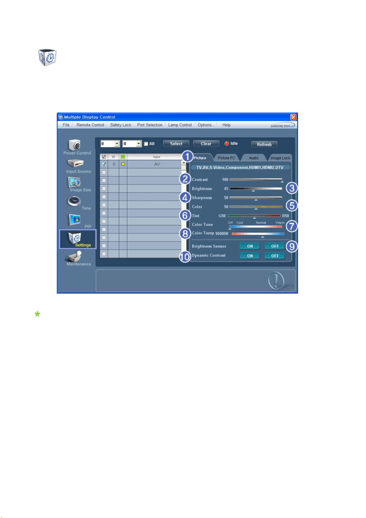
1. Click Settings of the main icons and the Settings Control screen appears.
Basic information required to adjust the Picture is displayed in the main menu. Settings for the selected monitor will
be displayed if one of the connected monitors is selected, and the default settings will be displayed if all monitors
are selected by clicking All and Select. If a value is changed in this screen, the current mode will automatically
switch to custom mode.
1) Picture
- Available only for TV, AV, S-Video, Component, HDMI1, HDMI2, DTV.
2) Contrast
usts Contrast of the selected display.
-Ad
3) Brightness
- Adjusts Brightness of the selected display.
4) Sharpness
usts Sharpness of the selected display.
-Ad
5) Color
usts Color of the selected display.
-Ad
6) Tint
- Adjusts Tint of the selected display.
- Available only for NT.
7) Color Tone
usts the Color Tone for the selected display.
-Ad
8)
Color Temp
Page 68
-Ad
j
j
j
j
usts the Color Temp for the selected display.
9) Brightness Sensor
usts the Brightness Sensor for the selected display.
-Ad
10) Dynamic Contrast
usts the Dynamic Contrast for the selected display.
-Ad
HDMI2 may not be supported depending on the product.
Brightness Sensor may not be supported depending on the product.
The Input source of MagicInfo works only on MagicInfo model.
Color Temp is only enabled if the Color Tone is set to Off.
The Input source of TV works only on TV model.
This feature is available only for the displays whose power status is ON and if no selection is made, the
factory default is displayed.
Settings
Picture PC
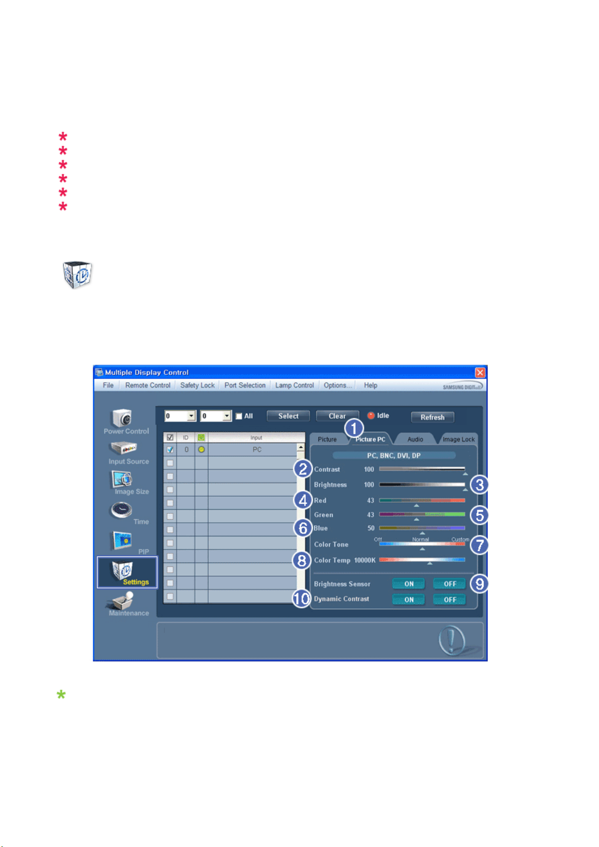
1. Click Settings of the main icons and the Settings Control screen appears.
Basic information required to adjust settings is displayed. Settings for the corresponding SET will be imported and
displayed on the slider if a display ID is selected, and the default settings will be displayed if all display IDs are
selected by clicking All and Select. If a value is changed in this screen, the current mode will automatically switch to
custom mode.
1) Picture PC
- Available only for PC, BNC, DVI and DP.
2) Contrast
usts Contrast of the selected display.
-Ad
Page 69

3) Brightness
j
j
j
j
j
j
j
j
-Ad
usts Brightness for the selected display.
4) Red
usts red Color of the selected display.
-Ad
- Available only for NT.
5) Green
usts green Color of the selected display.
-Ad
- Available only for NT.
6) Blue
usts blue Color of the selected display.
-Ad
- Available only for NT.
7) Color Tone
usts the Color Tone for the selected display.
-Ad
8) Color Temp
usts the Color Temp for the selected display.
-Ad
9) Brightness Sensor
usts the Brightness Sensor for the selected display.
-Ad
10) Dynamic Contrast
usts the Dynamic Contrast for the selected display.
-Ad
DP may not be supported depending on the product.
Brightness Sensor may not be supported depending on the product.
The Input source of MagicInfo works only on MagicInfo model.
The Input source of TV works only on TV model.
Color Temp is only enabled if the Color Tone is set to Off.
This feature is available only for the displays whose power status is ON and if no selection is made, the
factory default is displayed.
Settings
Audio
1. Click Settings of the main icons and the Settings Control screen appears.
Page 70
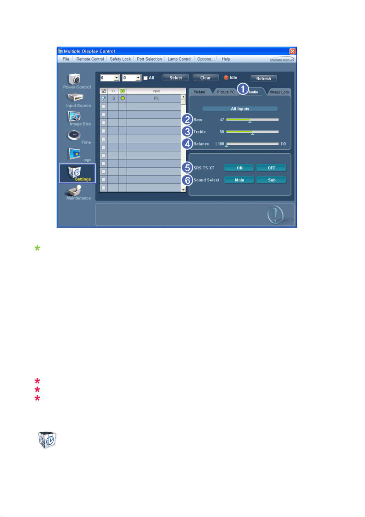
Basic information required to adjust Audio is displayed in the display window. Settings for the corresponding SET will
j
j
j
be imported and displayed on the slider if a display ID is selected, and the default settings will be displayed if all
display IDs are selected by clicking All and Select. If a value is changed in this screen, the current mode will
automatically switch to custom mode.
1) Audio
- Controls audio settings for all input sources.
2) Bass
usts Bass of the selected display.
-Ad
3) Treble
usts Treble of the selected display.
-Ad
4) Balance
usts Balance of the selected display.
-Ad
5) SRS TS XT
- SRS TS XT Sound ON/OFF of the selected display.
6) Sound Select
- Select either Main or Sub when PIP is On.
The Input source of MagicInfo works only on MagicInfo model.
The Input source of TV works only on TV model.
This feature is available only for the displays whose power status is ON and if no selection is made, the
factory default is displayed.
Settings
Image Lock
1. Click Settings of the main icons and the Settings Control screen appears.
Page 71
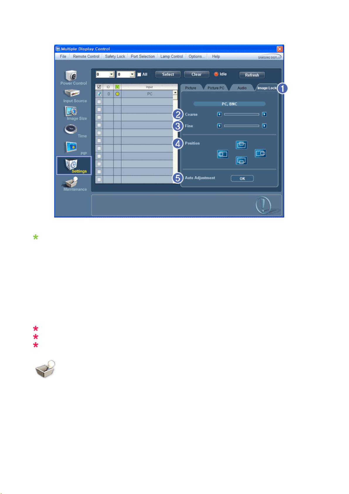
Info Grid shows some basic information necessary to Settings Control.
1) Image Lock
- Available only for PC, BNC.
2) Coarse
- Adjusts Coarse of the selected display.
3) Fine
- Adjusts Fine of the selected display.
4) Position
- Adjusts Position of the selected display.
5) Auto Adjustment
- Self-Adjust to the incoming PC signal.
The Input source of MagicInfo works only on MagicInfo model.
The Input source of TV works only on TV model.
Settings Control is available only for the displays for which the power status is ON.
Maintenance
Lamp Control
1. Click on the "Maintenance" icon in the Main Icon column to display the Maintenance screen.
Page 72
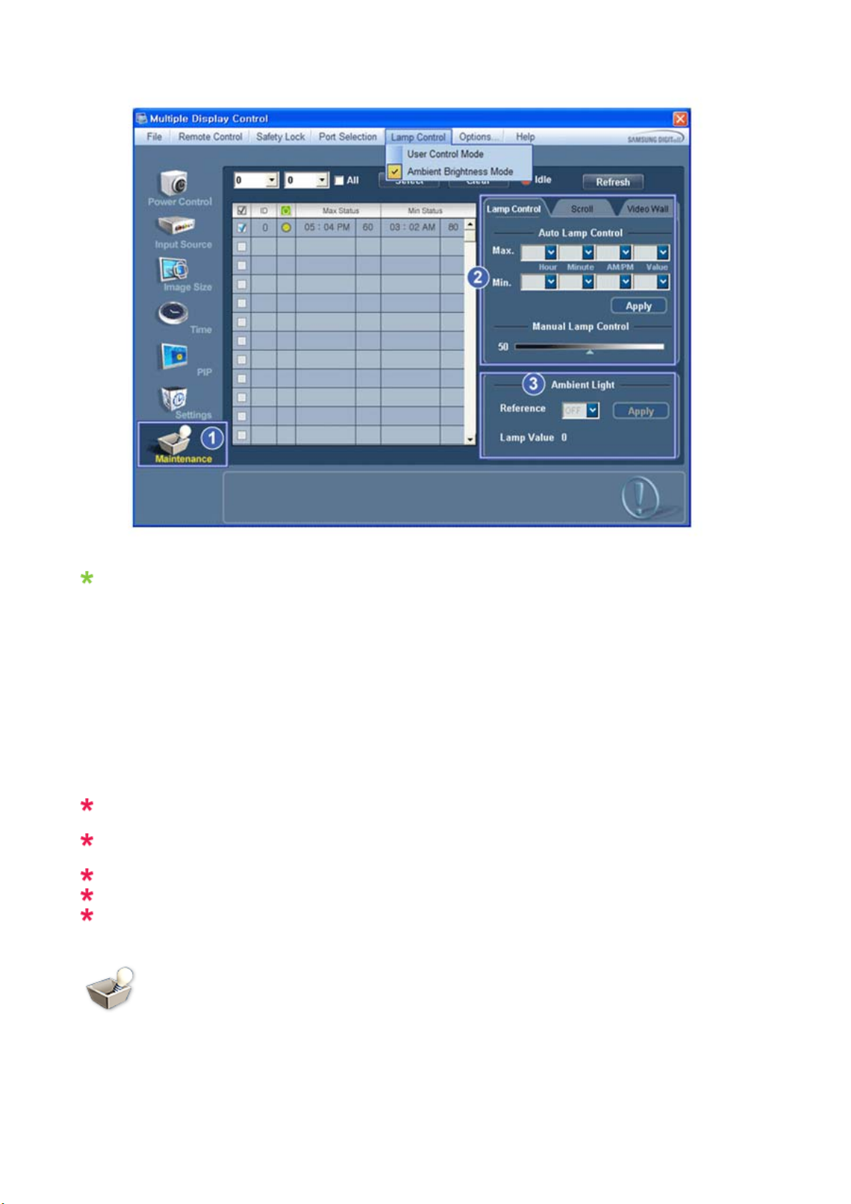
An "Info Grid" showing several basic data items appears.
T
T
1) Maintenance
- Allows the Maintenance Control function for all input sources.
2) Lamp Control
- Automatically adjusts the backlight of the selected display at a specified time.
he Manual Lamp Control automatically turns off if you adjust using the Auto Lamp Control.
- Allows you to adjust the backlight of the selected display regardless of the time.
he Auto Lamp Control automatically turns off if you adjust using the Manual Lamp Control.
3) Ambient Light
- Detects the ambient light intensity at the designated monitor and automatically adjusts the picture brightness.
- You can specify a Reference value and designate a monitor that will automatically determine Lamp Value (the light
intensity from the lamp), based on the ambient light intensity.
Ambient Light is only supported for models that have a brightness sensor and is only enabled when
Ambient Brightness Mode is selected in the Lamp Control menu.
Auto Lamp Control and Manual Lamp Control are only enabled when User Control Mode is selected in
the Lamp Control menu.
The Maintenance Control feature is available only for the displays whose power status is ON.
The Input source of MagicInfo works only on MagicInfo model.
The Input source of TV works only on TV model.
Maintenance
Scroll
1. Click on the "Maintenance" icon in the Main Icon column to display the Maintenance screen.
Page 73
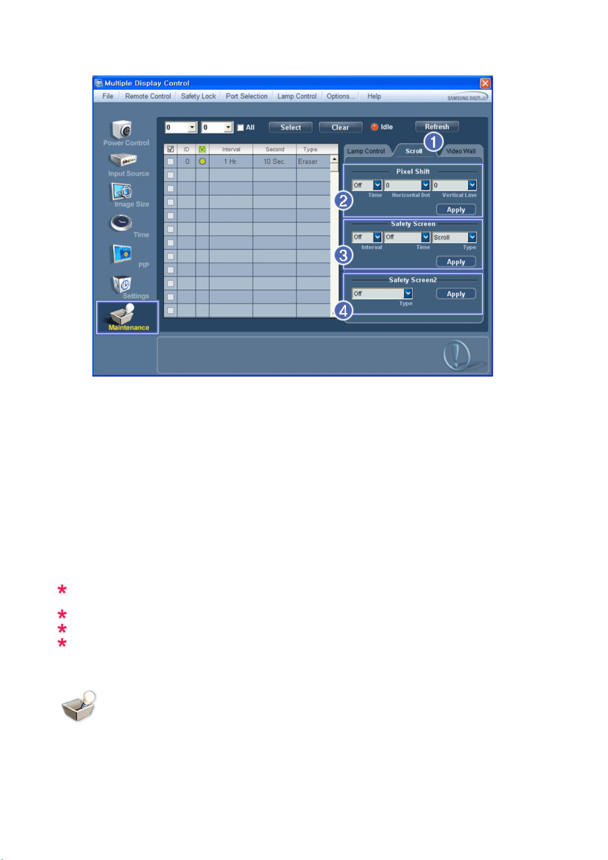
1) Scroll
- This function is used to remove the afterimages that occur when a still screen is displayed on the selected
display
for a long time.
2) Pixel Shift
- This allows the screen to be moved finely at the specified time interval.
3) Safety Screen
- The Safety Screen function is used to prevent afterimages from occurring when a still screen is displayed on the
monitor for a long time. The Interval item is used to set the repetition cycle in hour units and the Time item is
used to set the time when the Safety Screen function must be performed.
The Type item can be set to Scroll, Pixel, Bar, Eraser, All White, or Pattern.
4) Safety Screen2
- This function is used to prevent afterimages from occurring. There are five (5) types that you can select and
control with this function.
For the Scroll type, the Time item can be set to 1, 2, 3, 4 or 5. For the Bar and Eraser types, it can be set
to 10, 20, 30, 40 or 50. For the All White and Pattern type, it can be set to 1, 5, 10, 20 or 30.
The Input source of MagicInfo works only on MagicInfo model.
The Input source of TV works only on TV model.
The Maintenance Control feature is available only for the displays whose power status is ON.
Maintenance
Video Wall
1. Click on the "Maintenance" icon in the Main Icon column to display the Maintenance screen.
Page 74
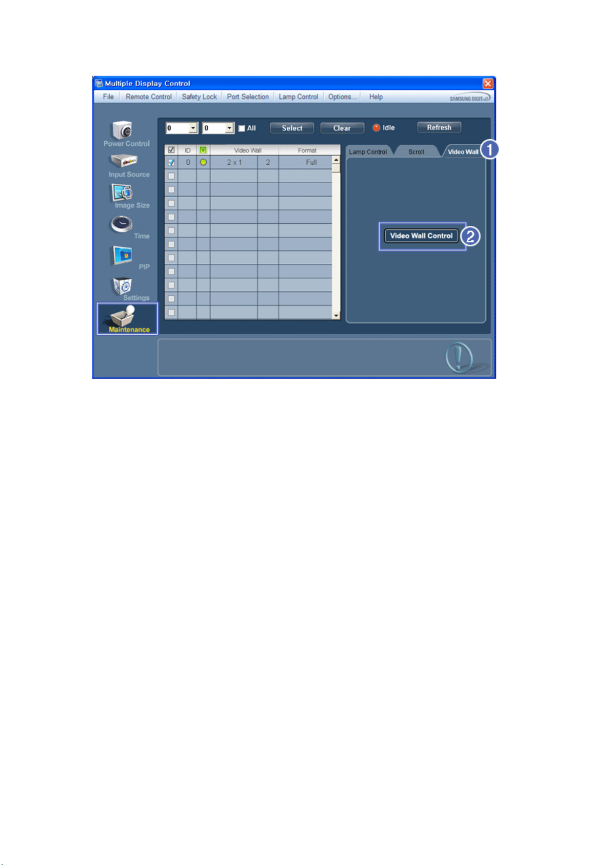
1) Video Wall
- A Video Wall is a set of video screens that are connected together, so that each screen shows a part of the whole
picture or so that the same picture is repeated on each screen.
2) Video Wall Control
- Video Wall properties can be configured.
Page 75
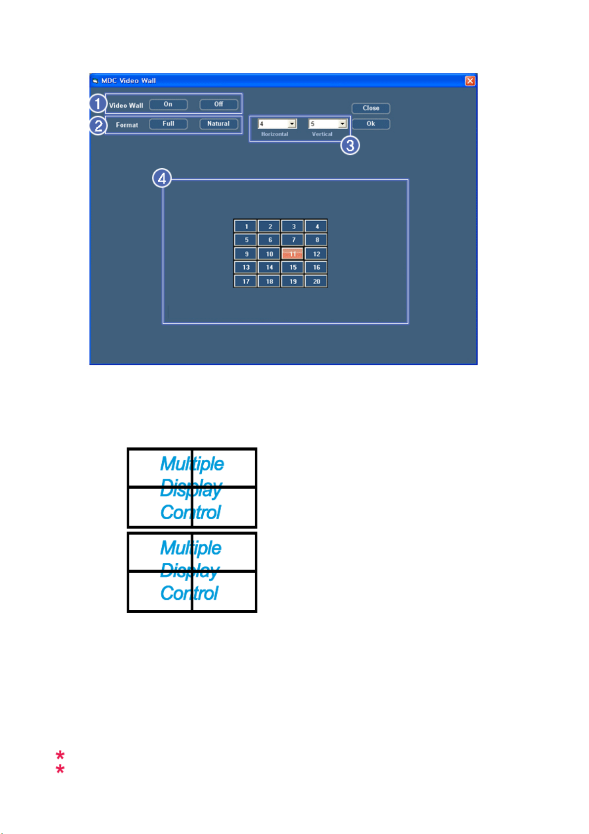
1) On / Off
T
T
urns on/off the Video Wall function of the selected display.
-
2) Format
he format can be selected to see a divided screen.
-
z Full
z Natural
3) Video Wall (Screen divider)
- The screen can be divided into.
You can select a number of screens with a different layout when dividing.
z Select a mode from Screen divider.
z Select a display from Display Selection.
z The place will be set up by pressing a number in the selected mode.
z The maximum number of monitors that can be arranged: Horizontal X Vertical = 100
z Up to 15 monitors can be arranged in a row. The maximum value for Horizontal is 6 if Vertical is set to 15 while
the maximum value for Vertical is 6 if Horizontal is set to 15.
4) Viewing Screen Splits
- You can view and change the layout of screens using the Screen Divider settings.
The range of the Screen Divider setting may differ depending on the model.
You may not operate this function in MagicInfo.
Page 76
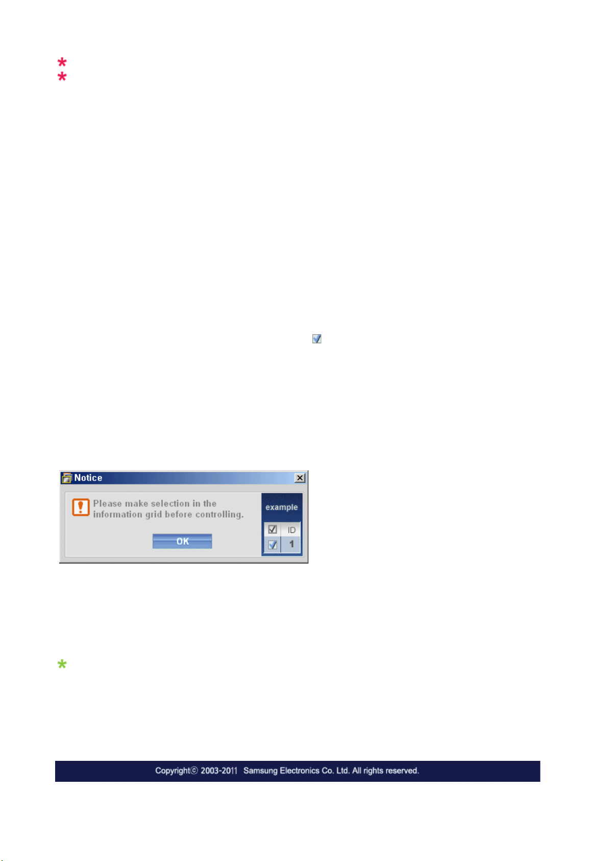
The Input source of TV works only on TV model.
The Maintenance Control function is available only for the displays where the power status is ON.
Troubleshooting
1. The display you wish to control does not appear on the Power Control Info Grid
- Check the connection of RS232C. (Check if it is properly connected to the Com1 port)
- Check the displays to see if any of the other displays connected have the same ID. If more than one displays have
the same ID, those displays are not properly detected by the program due to data conflict.
- For monitors that support a Set ID between 0 to 99, you have to set the Set ID to a value between 0 and 99.
Note : Check if the Set ID of the monitor is a value between 0 and 99 (set the value using the Display menu).
2. The display you wish to control does not appear on the other Control Info Grids
- Check to see if the display power is ON. (You can check this in Power Control Info Grid)
- Check if you can change the input source of the display.
3. The dialogue box appears repeatedly.
- Check to see if the display you wish to control is selected.
4. Both On Timer and Off Timer have been set but different time is showing.
- Apply current time to synchronize the display clocks.
5. The remote may not function properly when you turn off the remote Function, disconnect the RS-232C cable, or exit
the program in an Irregular manner. Rerun the program and turn the remote function again to Restore normal
functions.
<Note> This program may malfunction due to problems in communication circuits or interference from electronic
appliances nearby.
Settings Value Display In Multiple Display Mode
When there are more than one displays connected, the settings values are displayed as follows.
1. No selection: Displays the Factory Default Value.
2. Selected one display: Fetches and displays the settings value for the selected display.
3. Selected one display (ID1) and add another display (ID3): The program, which was displaying the settings value of
ID 1, fetches and displays the value of ID3.
4. If all sets are selected at the same time by clicking All and Select, the default value will be restored.
Page 77
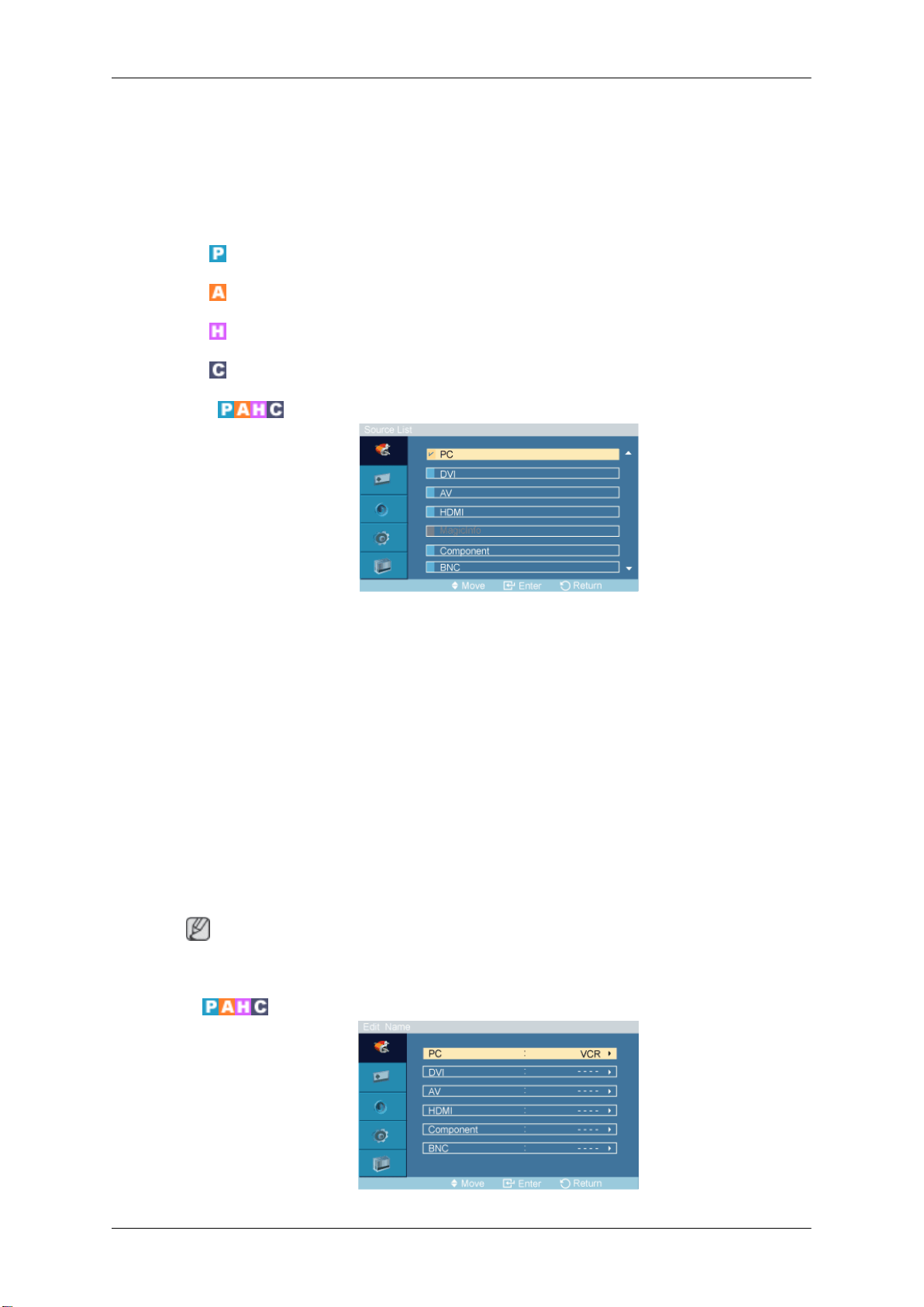
Adjusting the PDP Display
Input
Available Modes
•
PC / DVI / BNC
•
AV
•
HDMI
•
Component
Source List
Use to select PC, DVI or other external input sources connected to the PDP Display. Use to select the
screen of your choice.
1. PC
2. DVI
3. AV
4. HDMI
5. MagicInfo - Enabled when a network box is connected.
6. Component
7. BNC
• The direct button on the remote control is the 'SOURCE' button.
Edit Name
Note
Page 78
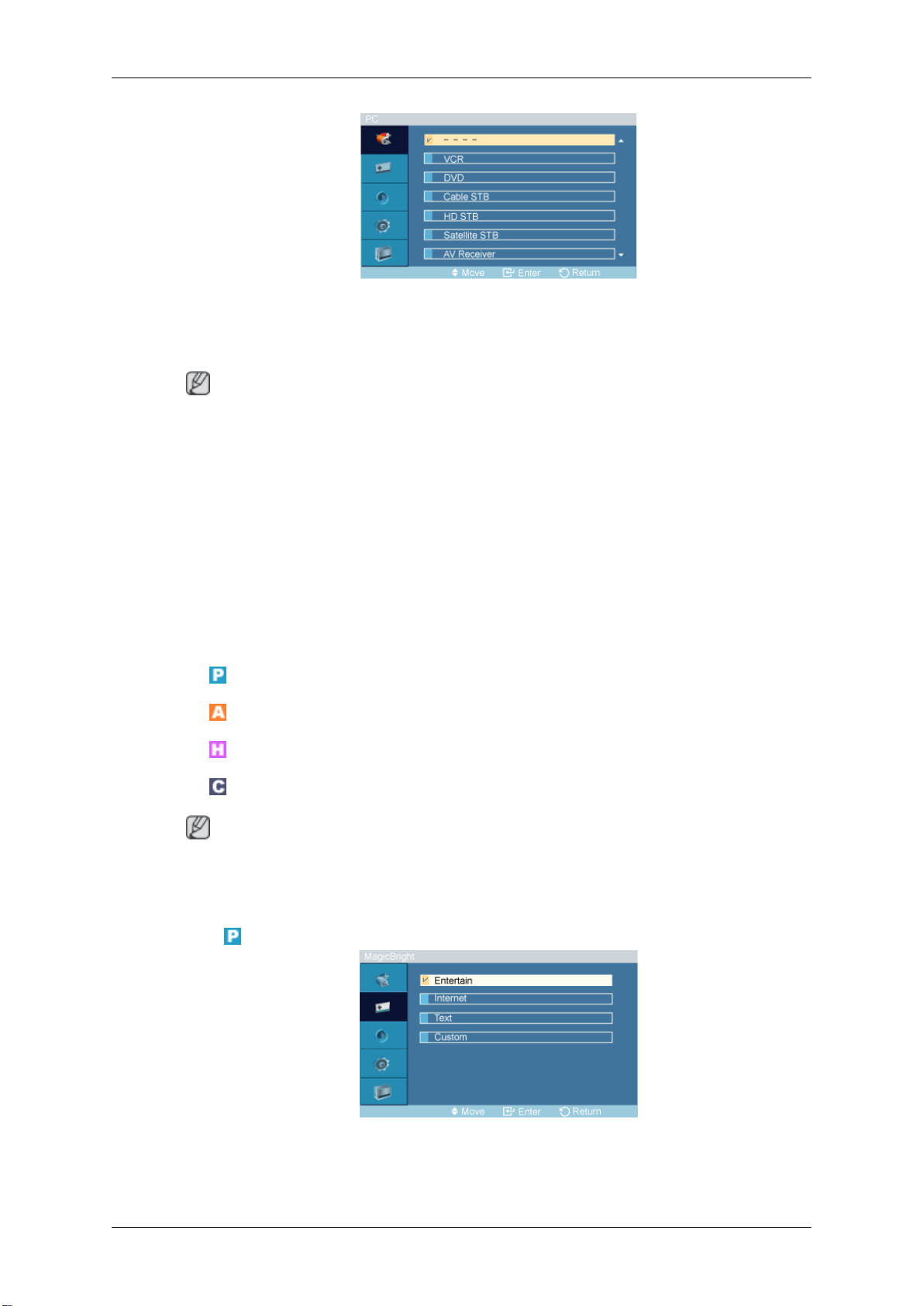
Adjusting the PDP Display
Name the input device connected to the input jacks to make your input source selection easier.
VCR / DVD / Cable STB / HD STB / Satellite STB
Camcorder / DVD Combo / DHR / PC
Note
• Set Edit Name to
In most other cases, set Edit Name to AV.
Note that Edit Name should be set to the connected source device if the source device's signal is
640 x 480, 720p (1280 x 720), or 1080p (1920 x 1080) because these signals are compatible with
both AV and PC input.
• The Picture menu changes depending on the input signal and Edit Name.
PC when a PC is connected via the HDMI or DVI port.
Picture [PC / DVI / BNC Mode]
Available Modes
•
PC / DVI / BNC
•
AV
•
HDMI
•
Component
/ AV Receiver / DVD Receiver / Game /
Note
• MagicInfo can only be enabled when a network box is connected.
The HDMI port and network box cannot be connected at the same time.
•
MagicBright
The MagicBright function is only enabled in PC mode. The function offers a picture that is twice as
bright and vivid as conventional monitors so that users' various needs (to prepare documents, use the
Internet, view videos, etc.) are satisfied.
Page 79
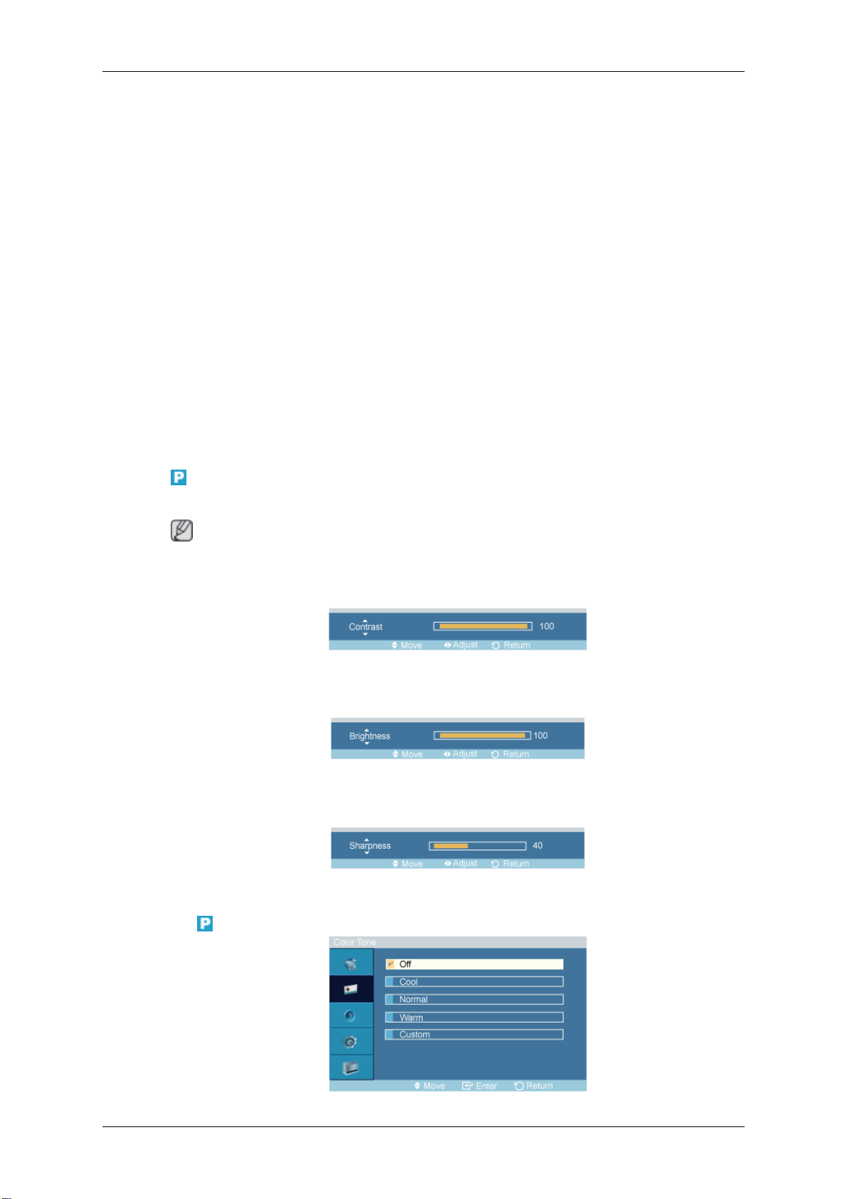
Adjusting the PDP Display
1. Entertain
High brightness
For watching motion pictures such as a DVD or VCR.
2. Internet
Medium brightness
For working with a mixture of images such as texts and graphics.
3. Text
Normal brightness
For documentations or works involving heavy text.
4. Custom
Custom
By using the on-screen menus, the contrast and brightness can be changed to your personal preference.
By adjusting the picture using the Custom function, MagicBright will change to Custom mode.
Contrast
Adjusts the Contrast.
Brightness
Adjusts the Brightness.
Although
comfortable to your eyes depending on your taste.
If this is the case, adjust the brightness and contrast by using the OSD menu.
Note
the values are
carefully chosen by our engineers, the pre-configured values may not be
Sharpness
Adjusts the Sharpness.
Color Tone
Page 80
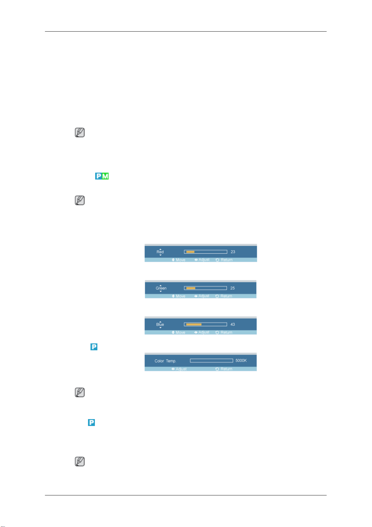
The color tones can be changed.
1. Off
2. Cool
3. Normal
4. Warm
5. Custom
Note
Adjusting the PDP Display
If you set the Color
If you set the Color Tone to Off, the Color Control function is disabled.
Color Control
Adjusts individual Red, Green, Blue color balance.
Note
you
If
mode.
Red
Green
Blue
adjust
Tone to Cool, Normal, Warm, or Custom, the Color Temp function is disabled.
the
picture by using the Color Control function, Color Tone will turn to the Custom
Color Temp.
Color Temp. is a measure of the 'warmth' of the image colors.
Note
This function is only enabled if the Color Tone is set to Off.
Image Lock
Image Lock is used to
with jitters and shakiness. If satisfactory results are not obtained using the Fine adjustment, use the
Coarse adjustment and then use Fine again.
Note
Available in PC mode only
fine-tune and get the best image by removing noise that creates unstable images
Page 81
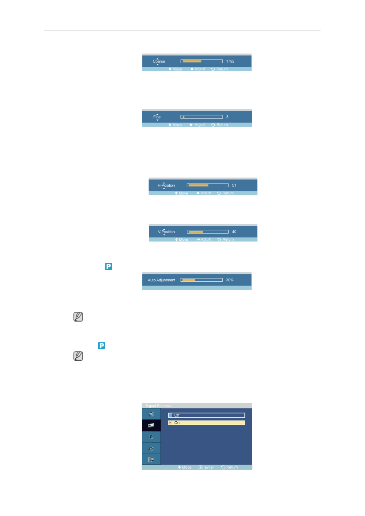
Coarse
Fine
Position
Adjusting the PDP Display
Removes noise such as vertical stripes. Coarse adjustment may move the screen image area. You may
relocate it to the center using the horizontal control menu.
Removes noise such as horizontal stripes. If the noise persists even after Fine tuning, repeat it after
adjusting the frequency (clock speed).
1. H-Position
Adjusts the screen location horizontally.
2. V-Position
Adjusts the screen location vertically.
Auto Adjustment
The values of Fine, Coarse, Position are adjusted automatically.
control panel, the auto function is performed.
Note
Enabled in PC or BNC mode only.
Signal Balance
Note
• Enabled in PC or BNC
By changing the resolution in the
mode only.
• This is used to make up for the weak RGB signal transmitted by a long signal cable.
Signal Balance
Page 82
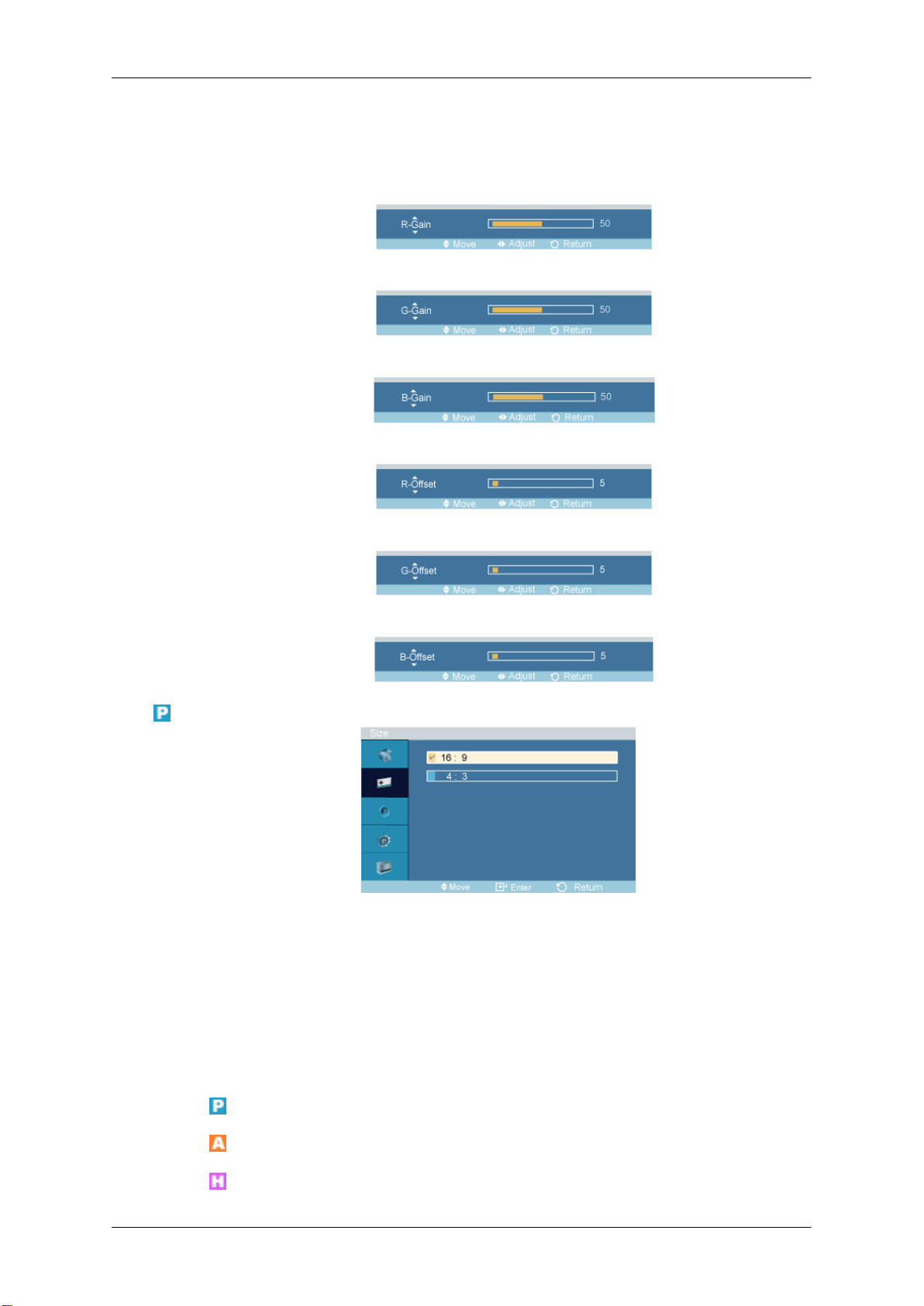
Selects either On or Off with the signal balance.
Signal Control
1. R-Gain
2. G-Gain
3. B-Gain
4. R-Offset
Adjusting the PDP Display
Size
5. G-Offset
6. B-Offset
The Size can be switched.
1. 16:9
2. 4:3
Picture [ AV / HDMI / Component Mode]
Available Modes
•
PC / DVI / BNC
•
AV
•
HDMI
Page 83
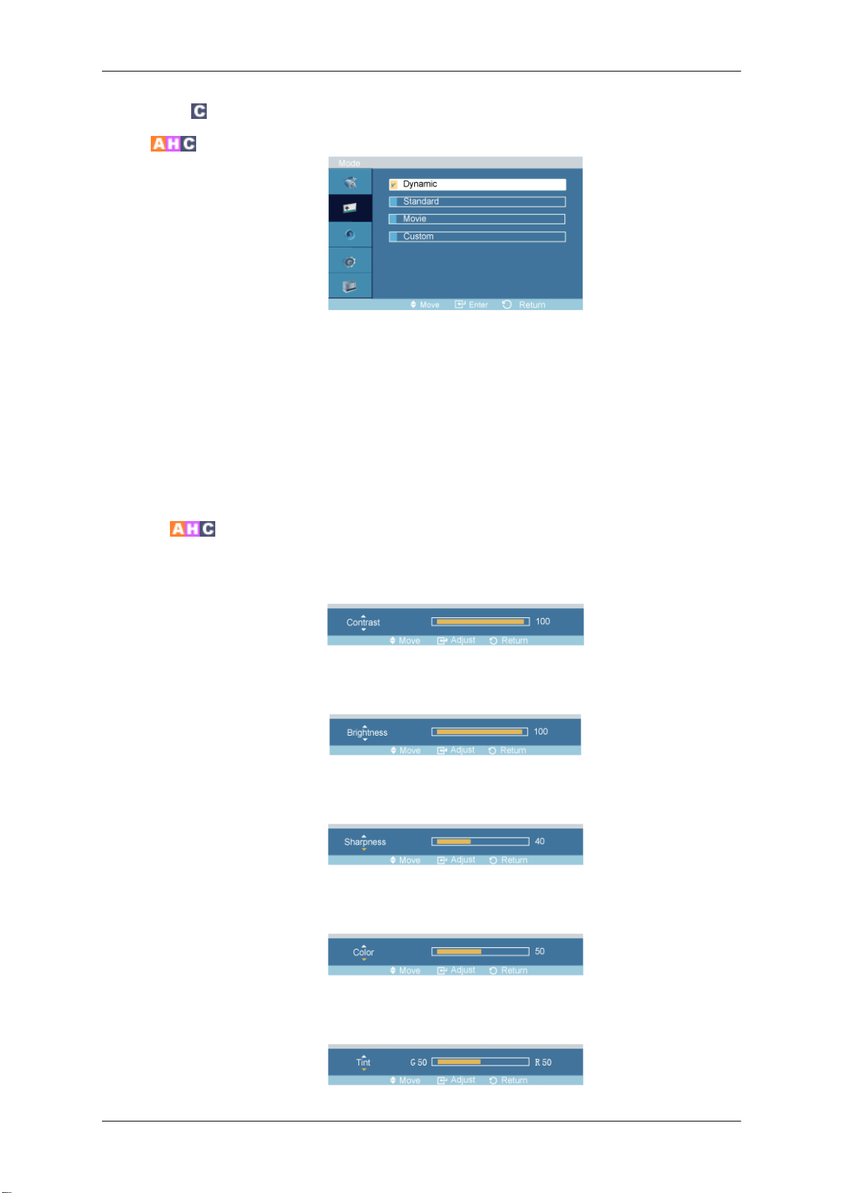
Mode
•
Adjusting the PDP Display
Component
The PDP Display has four automatic picture settings ("Dynamic",
tom") that are preset at the factory.
Dynamic, Standard, Movie, or Custom can be activated.
1. Dynamic
2. Standard
3. Movie
4. Custom
Custom
By using the on-screen menus, the contrast and brightness can be changed to your personal preference.
Contrast
Adjusts the Contrast.
Brightness
"Standard
",
"Movie
" and "Cus-
Adjusts the Brightness.
Sharpness
Adjusts the picture Sharpness.
Color
Adjusts the picture Color.
Tint
Page 84
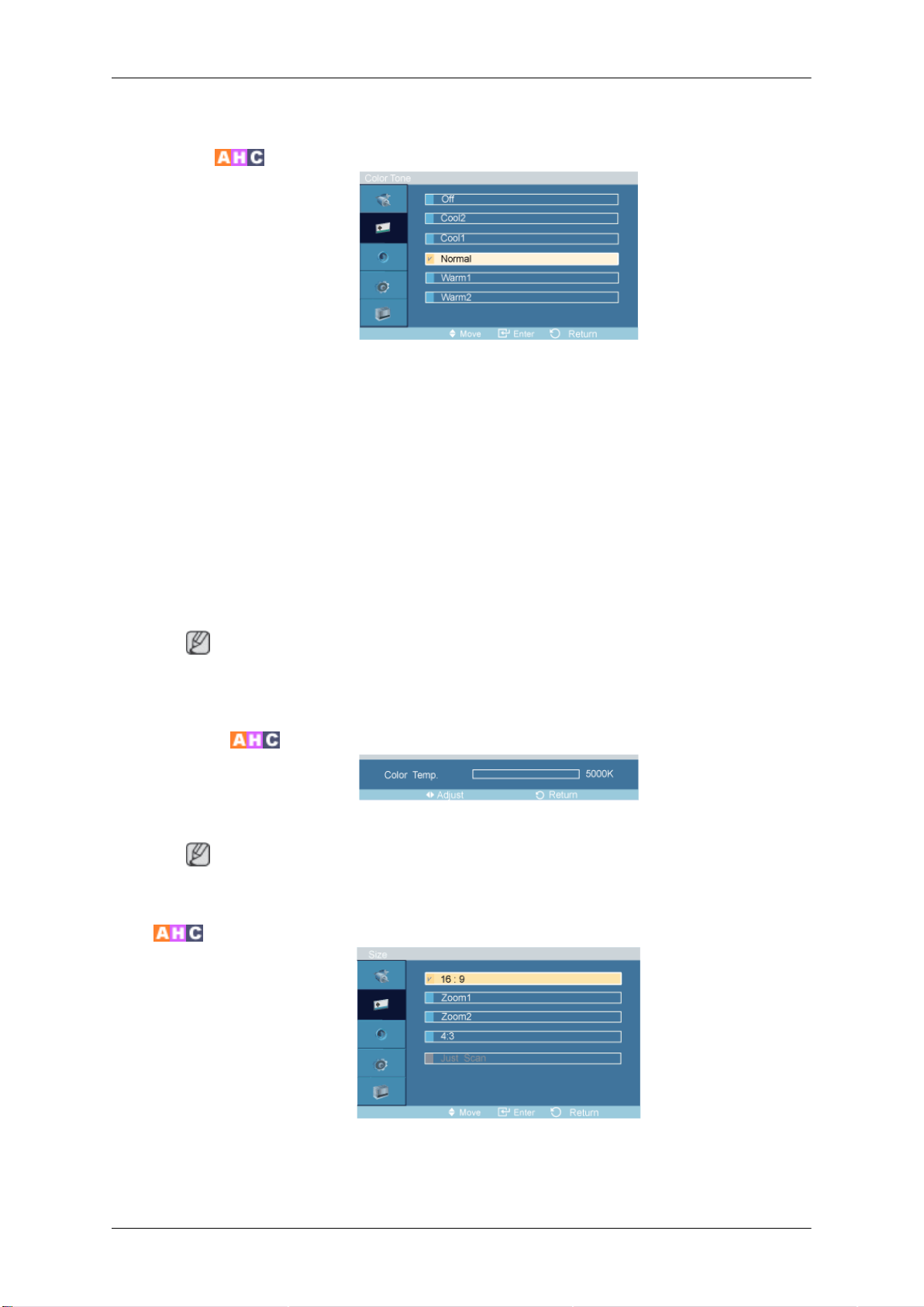
Adds a natural tone to the display.
Color Tone
The color tones can be changed. The individual Color components are also user adjustable.
1. Off
2. Cool2
3. Cool1
Adjusting the PDP Display
4. Normal
5. Warm1
6. Warm2
Note
If you set the Color Tone to Cool2, Cool1, Normal, Warm1, or Warm2, the Color Temp function
is disabled.
Color Temp.
Color temp. is a measure of the 'warmth' of the image colors.
Note
This function is only enabled if the Color Tone is set to Off.
Size
The Size can be switched.
1. 16:9 - Sets the picture to 16:9 wide mode.
Page 85
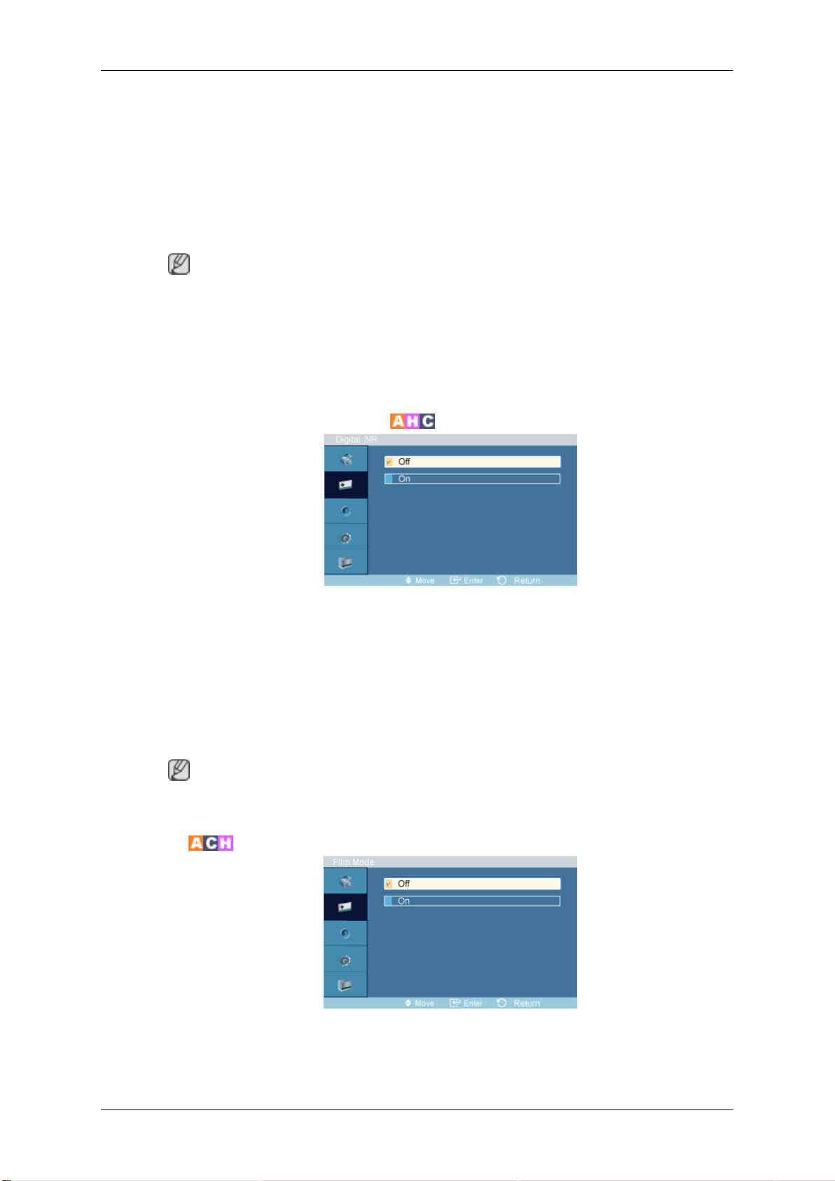
Adjusting the PDP Display
2. Zoom 1 - Magnifies the size of the picture on the screen.
3. Zoom 2 - Magnifies the size of the picture more than “Zoom 1”.
4. 4:3 - Sets the picture to 4:3 normal mode.
5. Just
• Certain external devices may feed the display an out of spec signal that may cause cutoff even
• Zoom1 and Zoom2 are not available in HDMI or Component mode.
• The Position and Reset functions are available in Zoom 1 or Zoom 2 modes.
Scan - Displays
nent 720p, 1080i, 1080p signals are input.
Note
when using the Screen Fit feature.
the input scenes as they are without any cutoff when HDMI / Compo-
Digital NR (Digital Noise Reduction)
Turns the Digital Noise Reduction feature Off/On. The Digital Noise
enjoy clearer and crisper images.
Reduction feature allows you to
Deactivated in HDMI / AV with a resolution of 1080p.
1. Off
2. On
Digital NR function is not available for all resolutions.
Film Mode
The Film Mode feature offers you a theater-quality viewing experience.
Film Mode is supported in AV, Component (480i / 1080i) and HDMI (480i / 1080i).
Note
Page 86
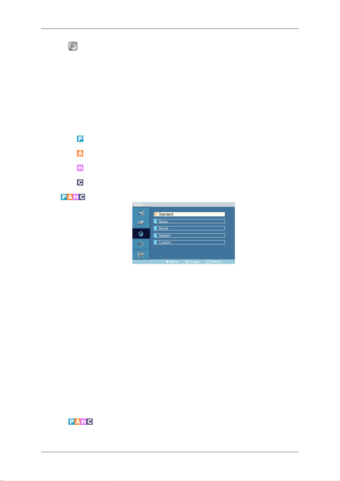
Note
Adjusting the PDP Display
Sound
Mode
• In HDMI mode,
be available with progressive scan signal.
1. Off
2. On
this function can be available when the input signal is interlaced scan; it cannot
Available Modes
•
PC / DVI / BNC
•
AV
•
HDMI
•
Component
Custom
The PDP Display has a built-in high fidelity stereo amplifier.
1. Standard
Selects Standard for the standard factory settings.
2. Music
Selects Music when watching music videos or concerts.
3. Movie
Selects Movie when viewing movies.
4. Speech
Selects Speech when watching a show that is mostly dialogue (i.e., news).
5. Custom
Selects Custom if you want to adjust the settings according to your personal preferences.
The sound settings can be adjusted to suit your personal preferences.
Page 87
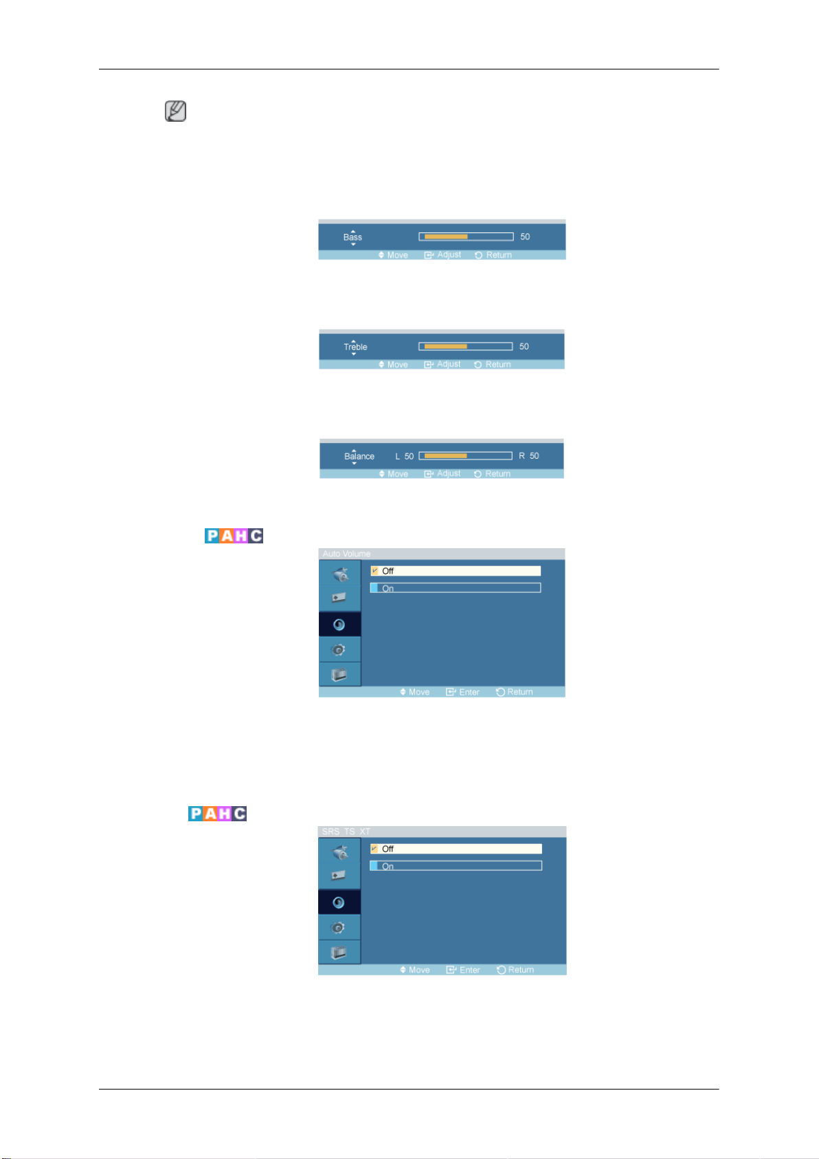
Adjusting the PDP Display
Note
• You can hear the sound even when sound value is set to 0.
• If you adjust sound using Custom
Bass
Emphasizes low frequency audio.
Treble
Emphasizes high frequency audio.
Balance
Allows you to Adjusts the sound balance between the left and right speakers.
Auto Volume
function, Mode will turn to Custom mode.
Reduces the difference in volume control between broadcasters.
1. Off
2. On
SRS TS XT
SRS TS XT is a patented
over two speakers. TruSurround delivers a compelling, virtual surround sound experience through any
two-speaker playback system, including internal television speakers. It is fully compatible with all
multichannel formats.
SRS technology that solves the problem of playing 5.1 multichannel content
Page 88
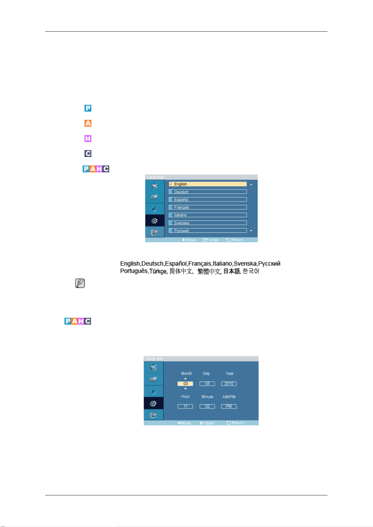
1. Off
2. On
Setup
Available Modes
•
•
•
•
Language
Adjusting the PDP Display
PC / DVI / BNC
AV
HDMI
Component
Time
Clock Set
You can choose one of 13 languages.
Note
The language chosen affects
on the computer.
You can set the time.
only the language of the OSD. It has no effect on any software running
Current Time Setting.
Page 89
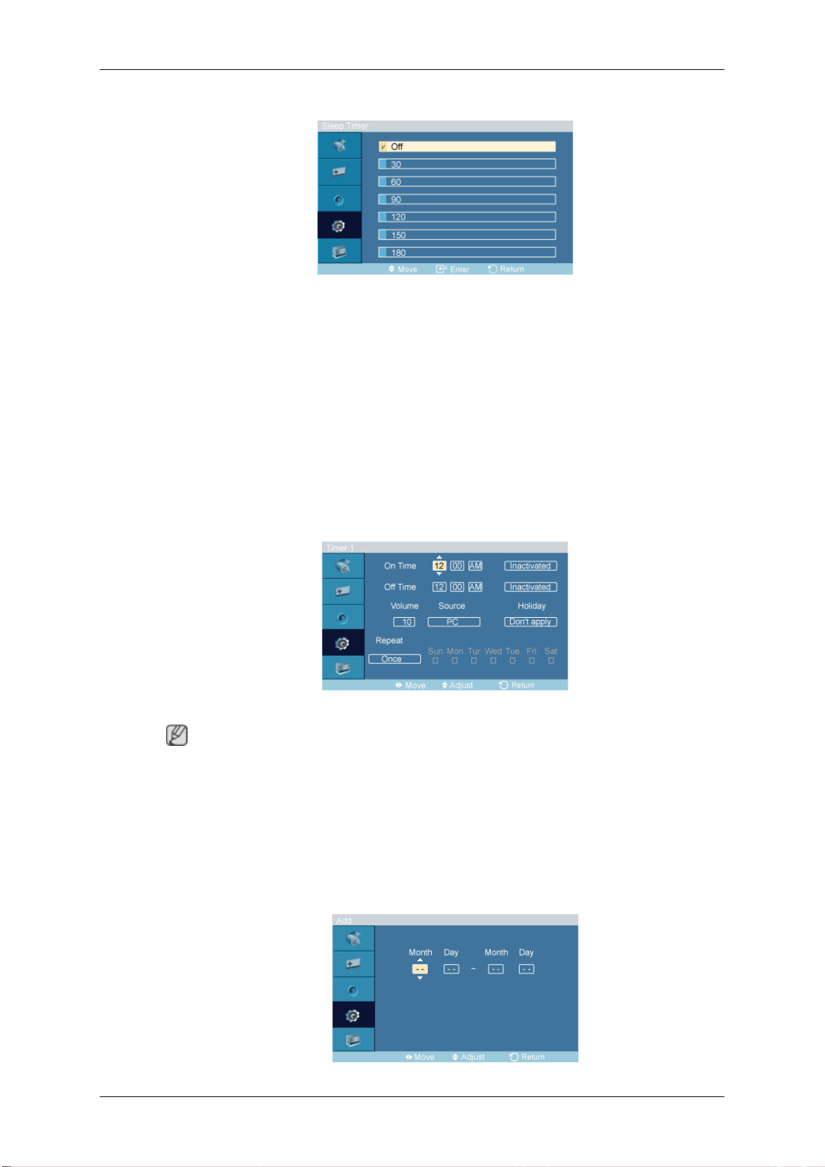
Sleep Timer
Turns the PDP Display off automatically at certain times.
1. Off
2. 30
3. 60
4. 90
5. 120
Adjusting the PDP Display
6. 150
7. 180
Timer1 / Timer2 / Timer3
You can set the PDP display to automatically turn on or off at a specified time.
Note
Only enabled when the clock is set using the Clock Set
•
The
•
• Holiday : When Choose Apply, timer is not available on holiday; when choose Don't apply, timer
Manual option allows you to select a day of the week.
is available on holiday.
menu.
Holiday Management
• Add
Page 90
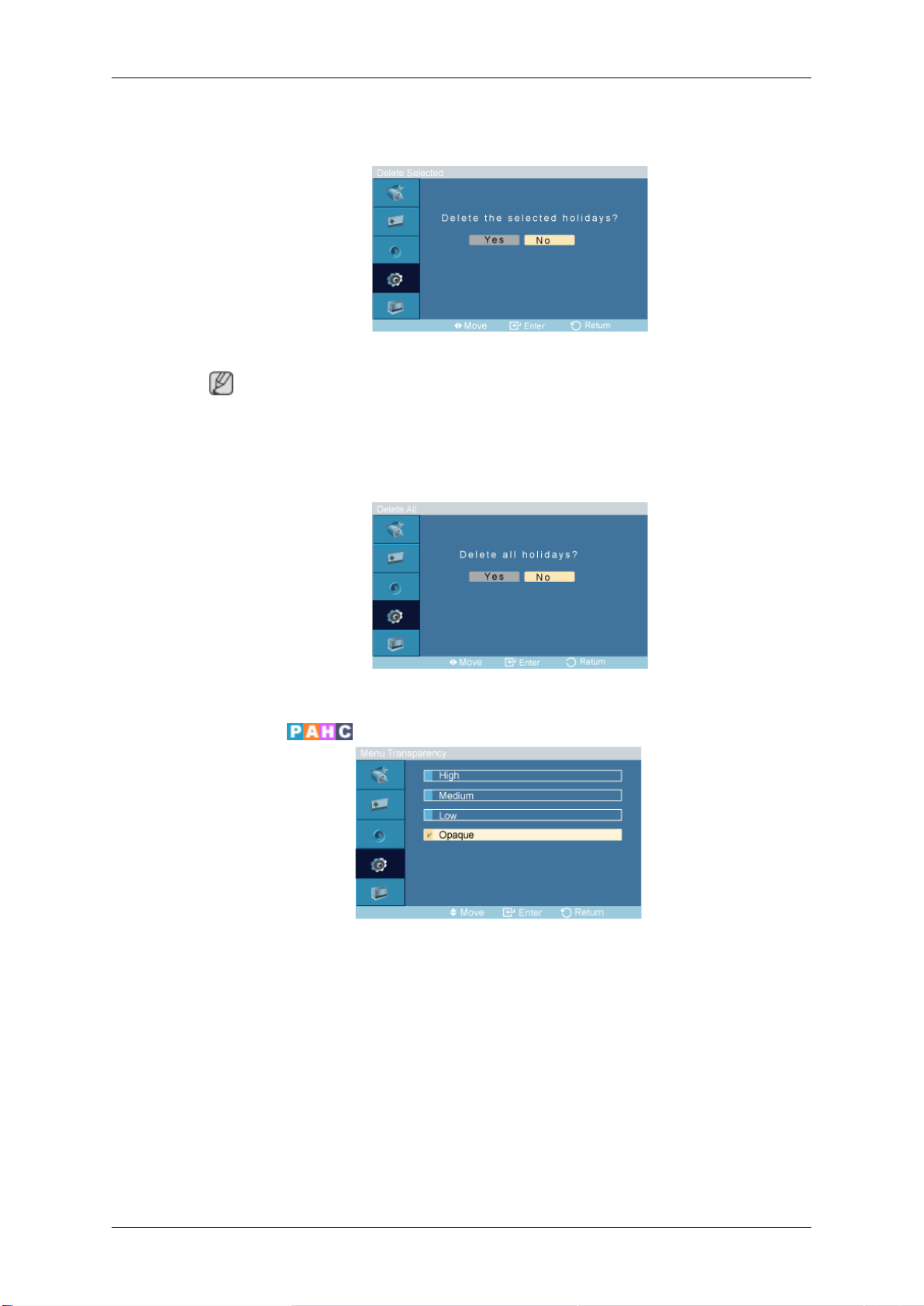
Adjusting the PDP Display
You can register holidays.
• Delete Selected
You can delete selected holidays.
Note
• Only enabled when registered holidays are selected.
• More than one holiday can be selected and deleted.
• Delete All
You can delete all the registered holidays.
Menu Transparency
Change the transparency of the background of the OSD.
1. High
2. Medium
3. Low
4. Opaque
Page 91
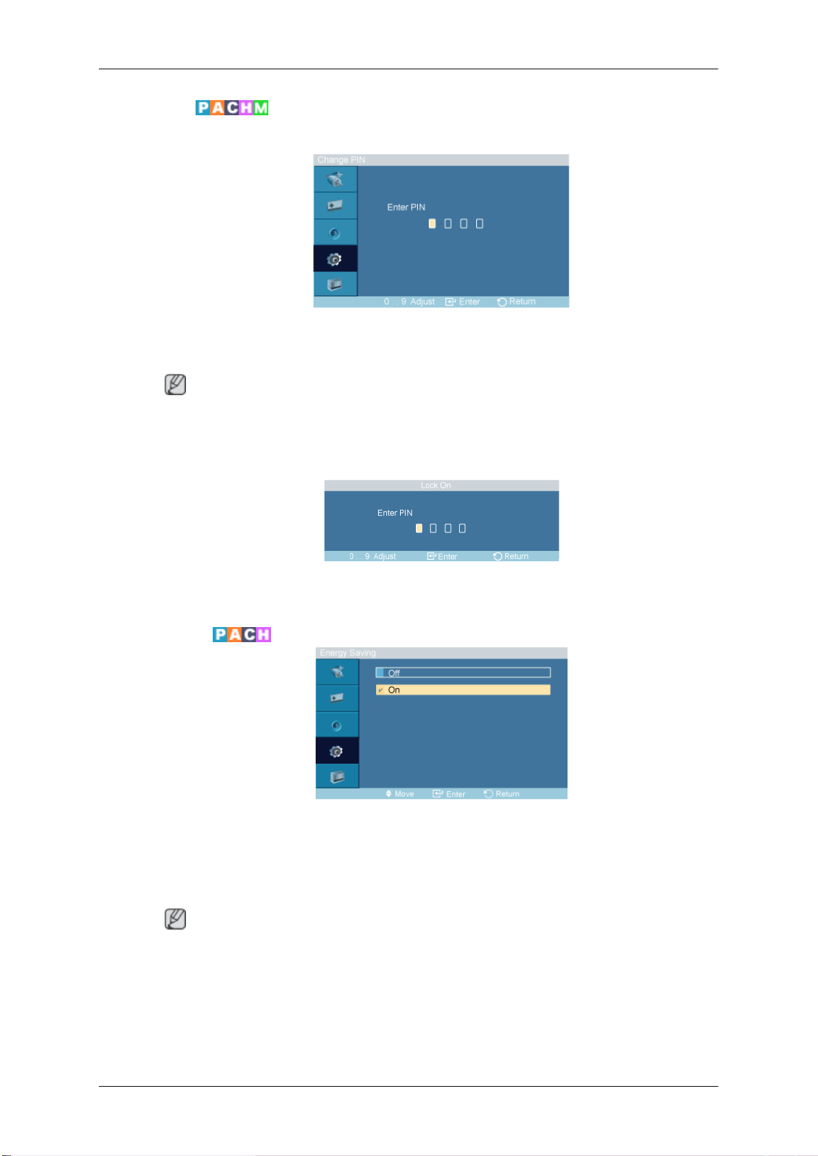
Safety Lock
Change PIN
The password can be changed.
The preset password for the PDP Display is "0000".
Adjusting the PDP Display
Note
• If you forgot your
to "0000."
Lock
This is the function that locks the OSD in order to keep the current settings or to prevent others from
adjusting the settings.
Energy Saving
password, press the remote buttons INFO + EXIT + MUTE to reset the password
This feature adjusts the power consumption of the unit in order to save energy.
1. Off
2. On
Note
If Energy Saving mode is Off, you can obtain the maximum display brightness.
Page 92
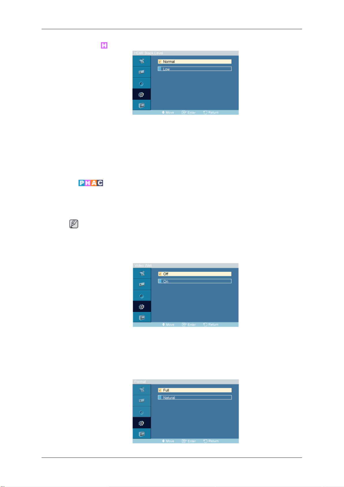
HDMI Black Level
When a DVD or set-top box is connected to your Product via HDMI, it may cause a degradation in the
screen quality, such as an increase in the black level, a low contrast, or discoloration, etc., depending
on the external device
HDMI Black Level.
1. Normal
2. Low
Video Wall
Adjusting the PDP Display
connected. In this case, adjust the screen quality of your TV by configuring the
A Video Wall is a
whole picture or where the same picture is repeated on each screen.
When the Video Wall is on, you can adjust the Video Wall screen setting.
When Video Wall is running,
Video Wall does not operate in MagicInfo mode.
Video Wall
Turns Off/On the Video Wall function of the selected display Off/On.
1. Off
2. On
set of video screens connected together, so that each screen shows a part of the
Note
the Auto Adjustment, Image Lock, and Size functions are not available.
Format
Page 93
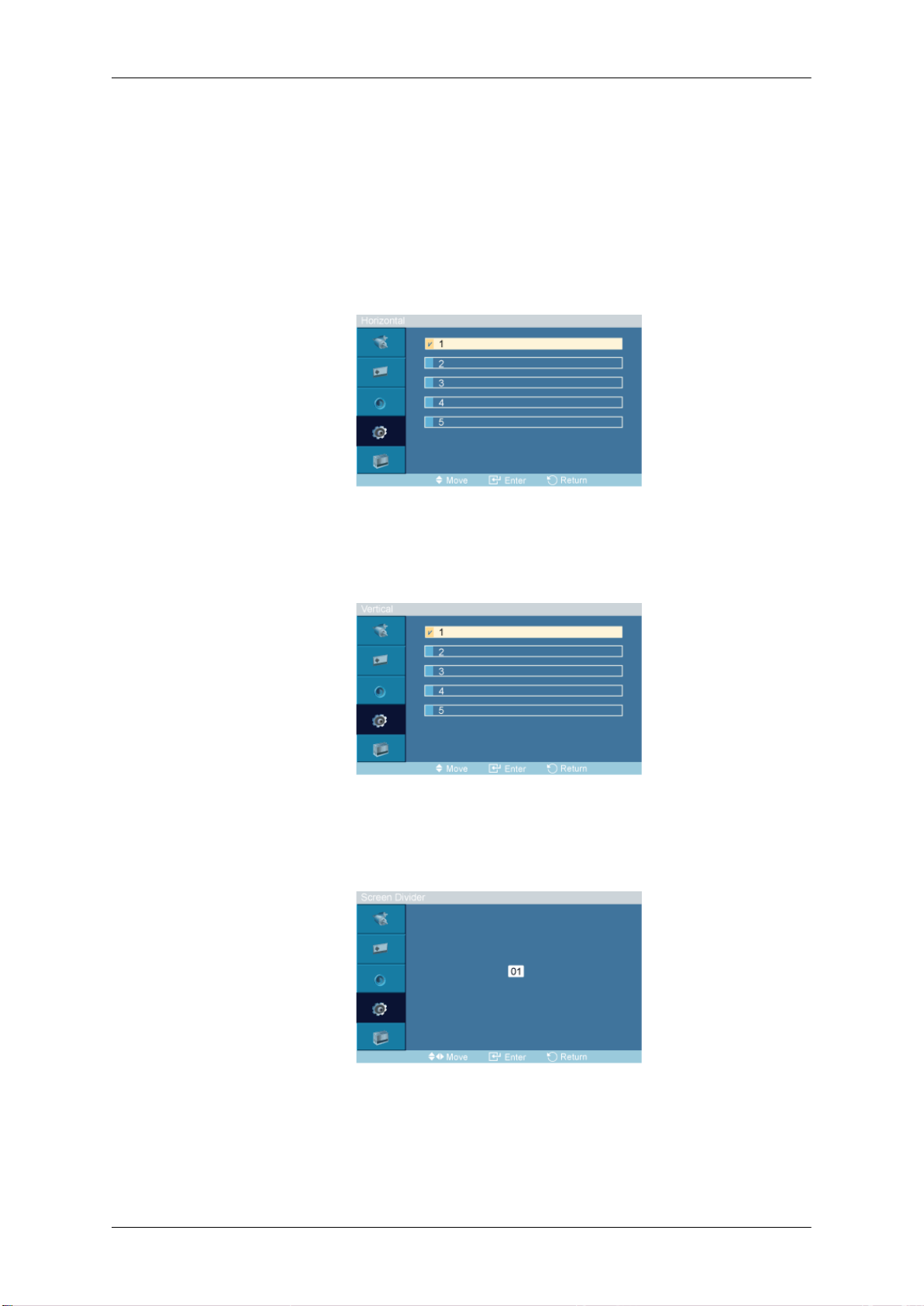
The Format can be selected to see a divided screen.
1. Full
2. Natural
Horizontal
Adjusting the PDP Display
Provides a full screen without any margins.
Displays a natural image with the original aspect ratio intact.
Sets how many parts the screen should be divided horizontally.
Five adjustment levels: 1, 2, 3, 4, and 5.
Vertical
Sets how many parts the screen should be divided vertically.
Five adjustment levels: 1, 2, 3, 4, and 5.
Screen Divider
The screen can be divided into several images. A number of screens can be selected with a different
layout when dividing.
• Select a mode in Screen Divider.
• Select a display in Display Selection.
Page 94
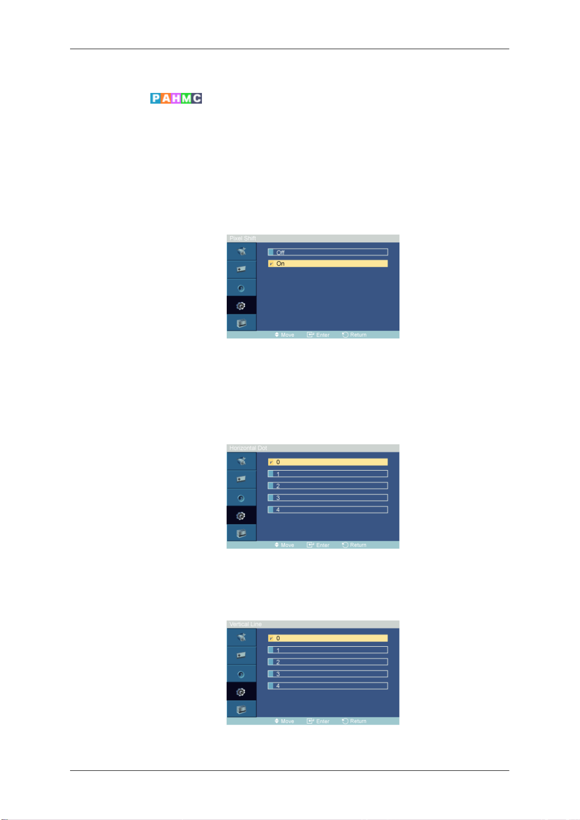
• The selection will be set up by pressing a number in the selected mode.
Safety Screen
The Safety Screen function is used to prevent afterimages that may appear when a still picture is
displayed on the screen over a long time.
Adjusting the PDP Display
• The Safety Screen
• This function is not available when the power is turned off.
Pixel Shift
Pixel Shift
To prevent after-images on the screen you can use this function, so that every minute pixels on the
PDP are moved in horizontal or vertical direction.
1. Off
2. On
Horizontal Dot
function scrolls the screen for the specified period of time.
Sets how many pixels the screen moves horizontally.
Five adjustment levels: 0, 1, 2, 3, and 4.
Vertical Line
Sets how many pixels the screen moves vertically.
Page 95
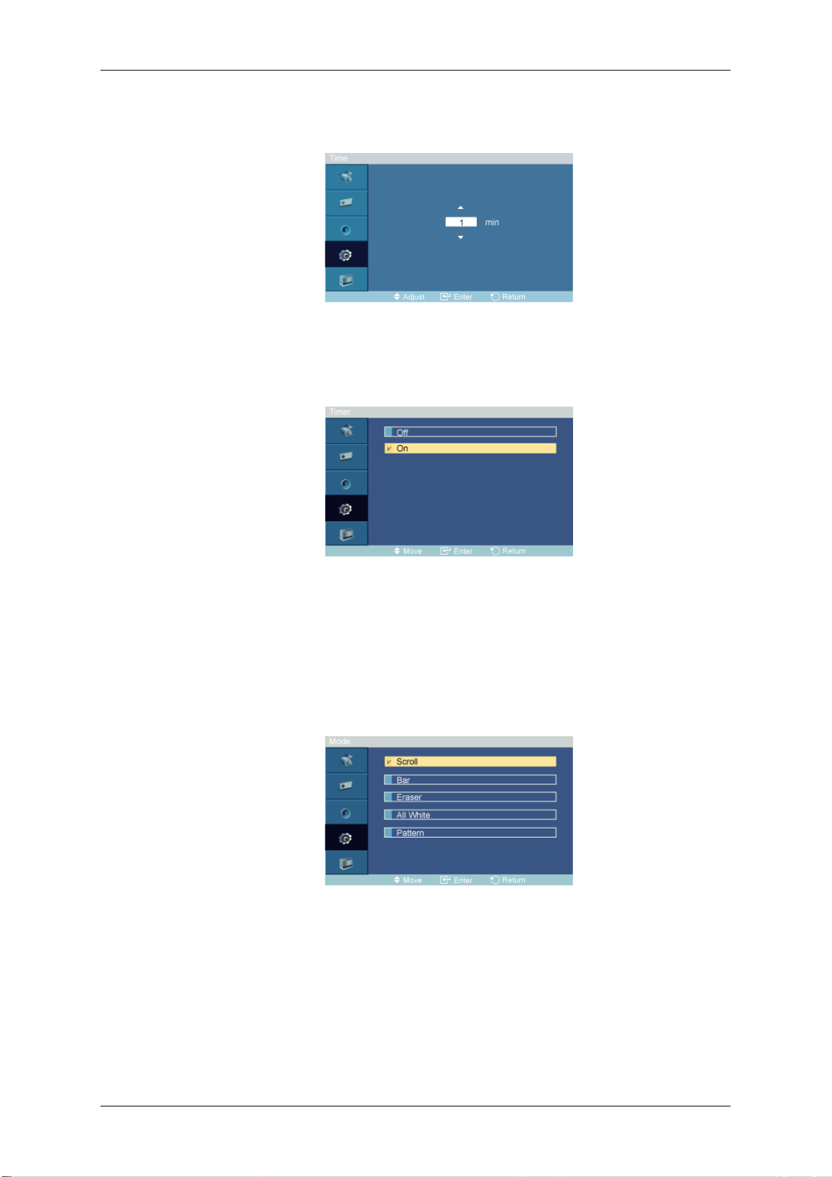
Time
Timer
Timer
Adjusting the PDP Display
Five adjustment levels: 0, 1, 2, 3, and 4.
Set the time interval for performing the horizontal or vertical movement, respectively.
Mode
You can set the timer for Screen Burn Protection.
If you start the
of time and then automatically finish.
1. Off
2. On
You can change the Safety Screen Type.
1. Scroll
2. Bar
operation to erase any residual image, the operation will be performed for the set period
3. Eraser
4. All White
5. Pattern
Page 96
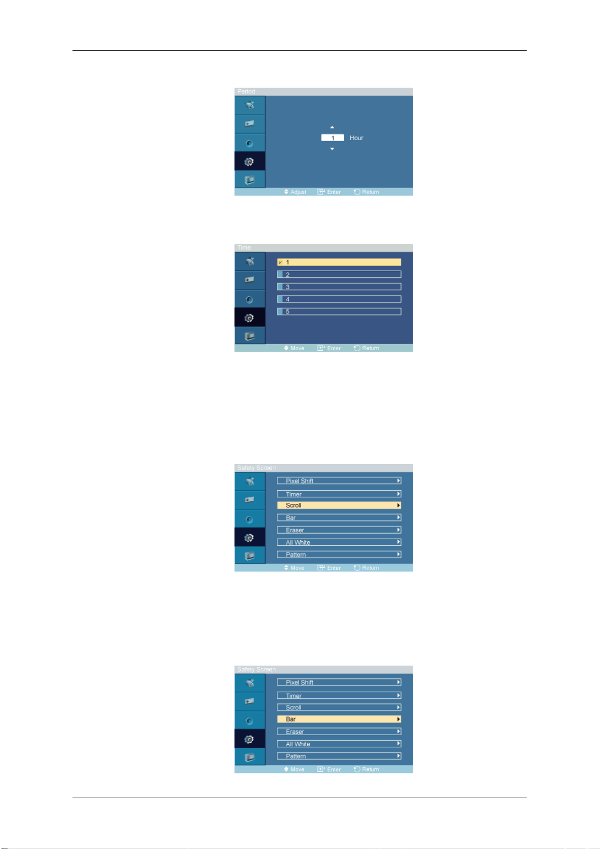
Period
Time
Adjusting the PDP Display
Use this function to set the execution period for each mode set in the timer.
Scroll
Bar
Within the set period of time specify a time for execution.
• Mode-Scroll : 1~5 sec
• Mode-Bar, Eraser : 10~50 sec
• Mode-All White, Pattern : 1, 5, 10, 20 30 min
This function prevents after-images on the screen by moving all the pixels on the PDP according to a
pattern.
Use this function when
you displayed a still image on the screen for a long time.
there are remaining after-images or symbols on the screen, especially when
Page 97
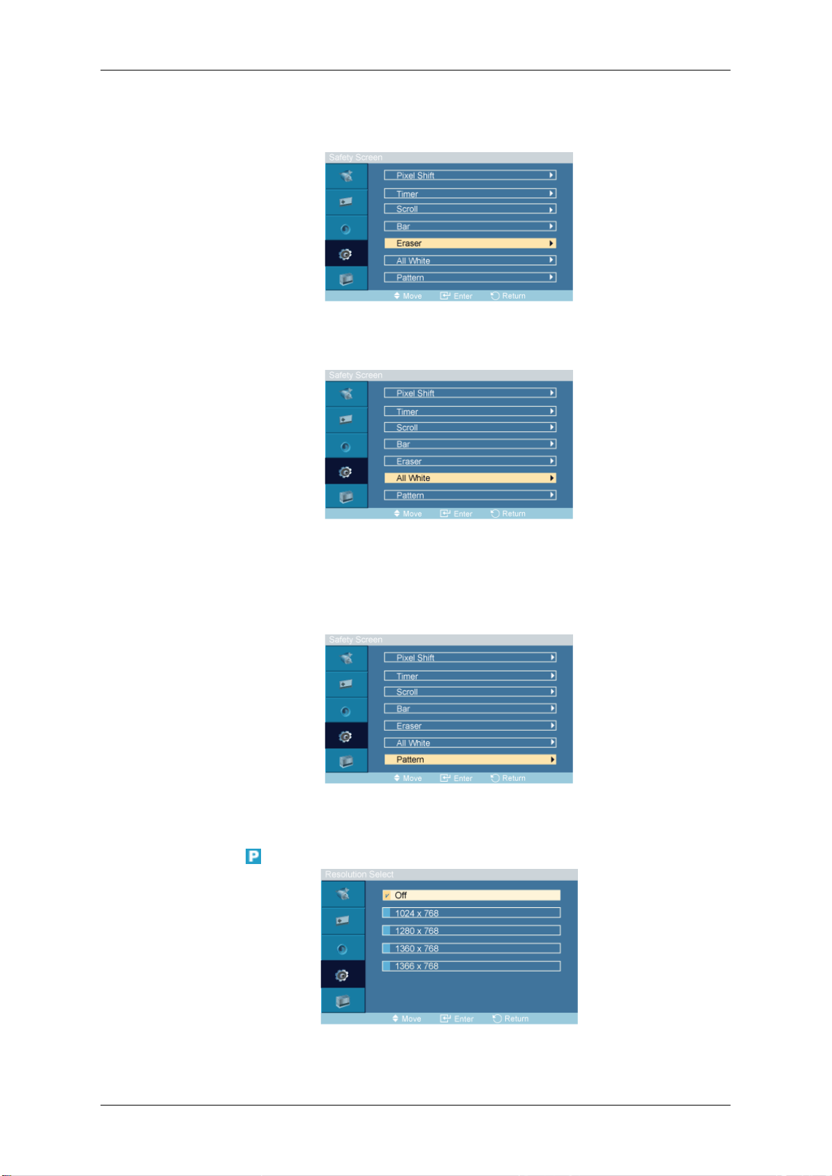
Eraser
All White
Adjusting the PDP Display
This function prevents after-images on the screen by moving long black and white vertical lines.
This function prevents after-images on the screen by moving a rectangular pattern.
This function prevents after-images on the screen by changing the color of pixels to white.
Use this function when
you displayed a still image on the screen for a long time.
Pattern
This function prevents after-images on the screen by moving a diagonal pattern stored in the panel
repeatedly.
Resolution Select
there are remaining after-images or symbols on the screen, especially when
When the picture is not displayed properly on the screen when setting the graphics card resolution of
the computer to 1024 x 768 @ 60Hz, 1280 x 768 @ 60Hz, 1360 x 768@ 60Hz or 1366 x 768 @
Page 98
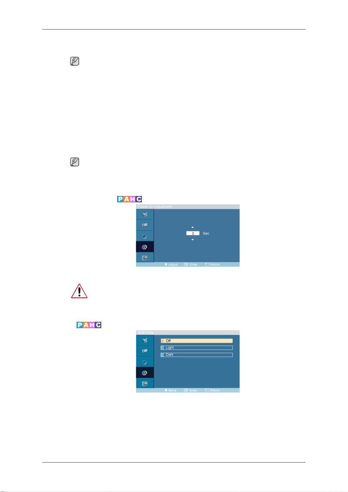
Adjusting the PDP Display
60Hz, by using this function(Resolution Select), you can have the picture displayed on the screen in
the specified resolution.
Note
Available in PC mode only
1. Off
2. 1024 x 768
3. 1280 x 768
4. 1360 x 768
5. 1366 x 768
Note
Selecting the menu is
x 768 @ 60Hz, 1360 x 768 @ 60Hz or 1366 x 768 @ 60Hz.
Power On Adjustment
Adjust the Power On time for the screen.
Caution: Set the Power On time to be longer to avoid overvoltage.
Side Gray
only allowed when the graphics resolution is set to 1024 x 768 @ 60Hz, 1280
Select the brightness of the grey for the screen background.
1. Off
2. Light
3. Dark
Page 99
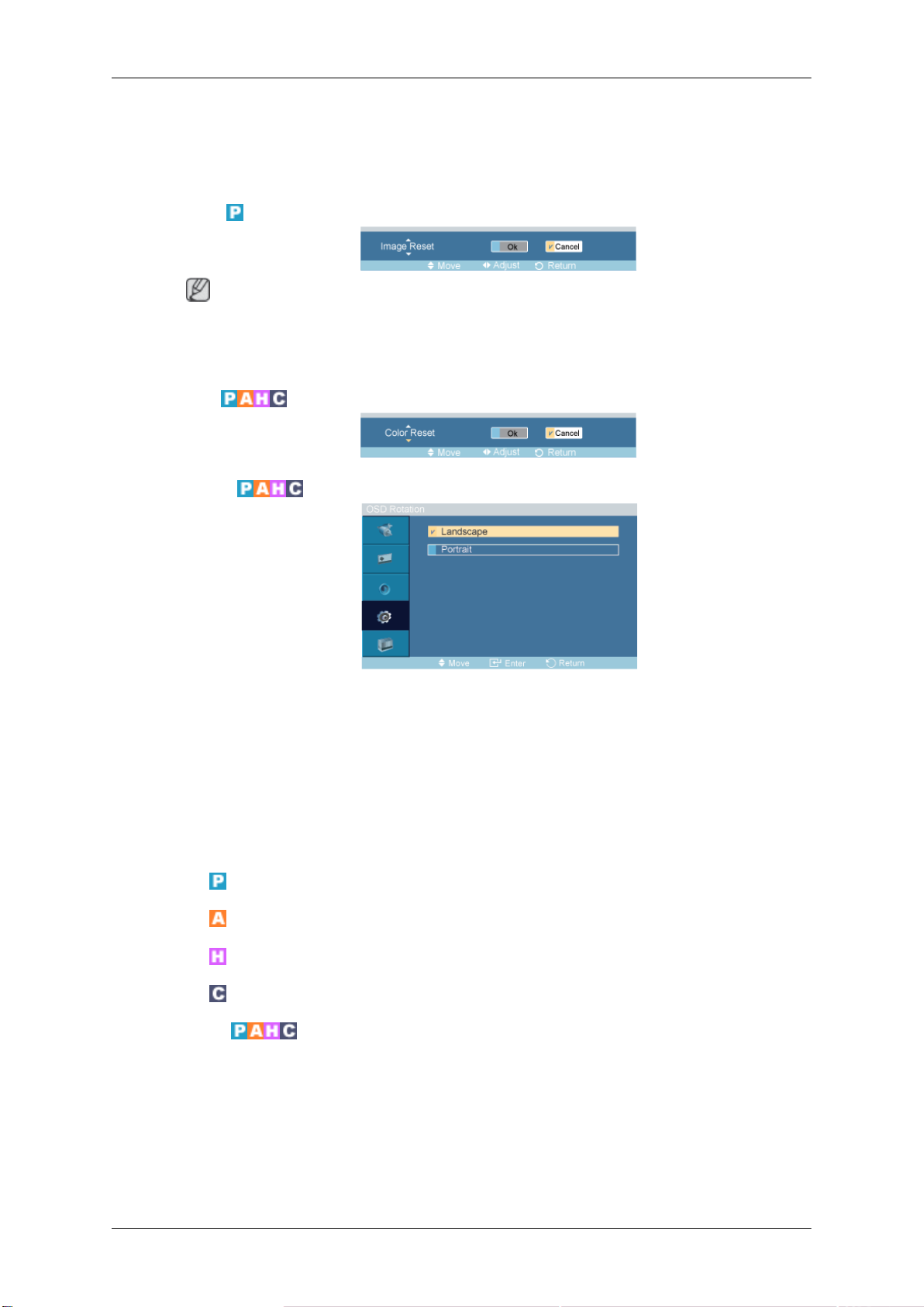
Reset
Adjusting the PDP Display
Reverts the product settings
is being used.
Image Reset
Note
Available in PC mode only
The Reset function is not available when Video Wall is On.
Color Reset
OSD Rotation
to factory defaults. The Reset function is only available when PC / DVI
OSD Rotate
1. Landscape
2. Portrait
Multi Control
Available Modes
•
•
•
•
Multi Control
Assigns an individual ID to the SET.
PC / DVI / BNC
AV
HDMI
Component
Page 100
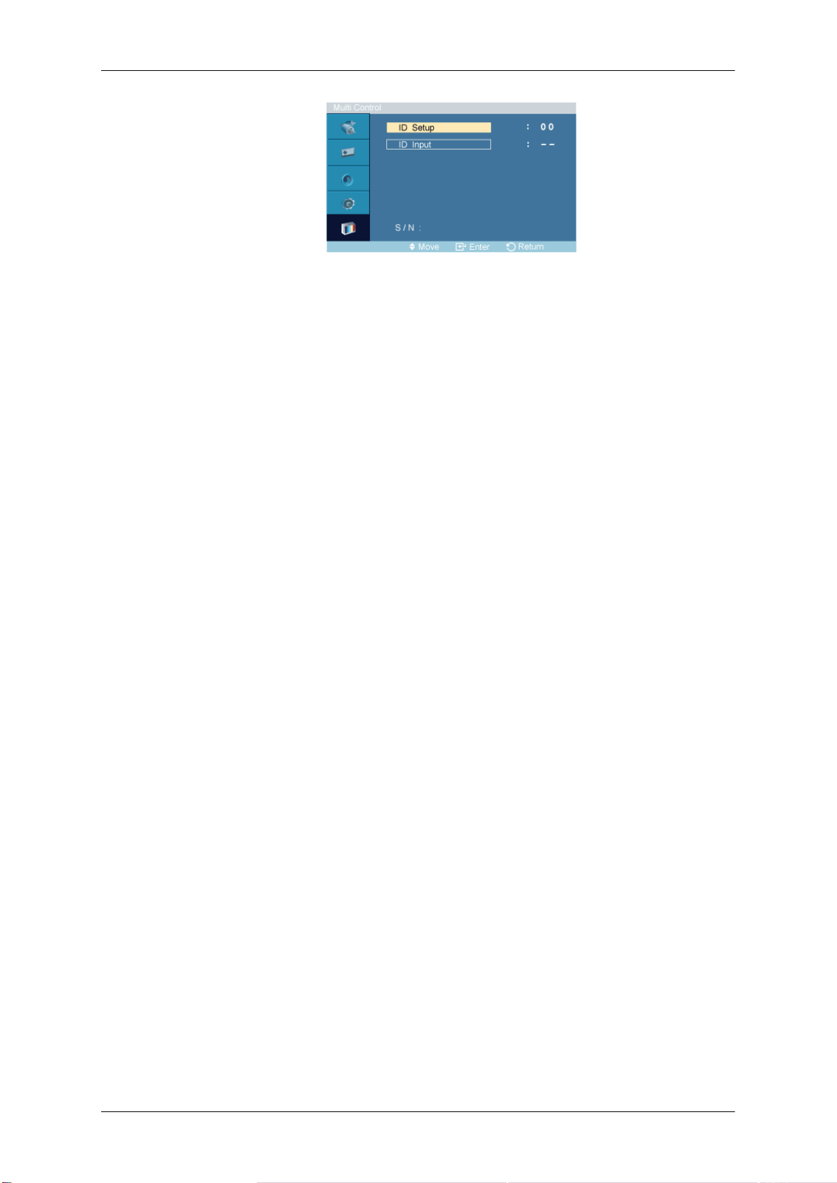
Adjusting the PDP Display
• ID Setup
Assigns distinctive IDs to the SET.
• ID Input
Use
select
to
to the transmitter setting becomes activated.
transmitter functions of the individual SET. Only a SET where the ID corresponds
the
 Loading...