

Samsung HW-T550XY User Manual

FULL MANUAL
HW-T550
Imagine the possibilities
Thank you fo r purchasing this Samsung produc t.
To receive more complete ser vice, please register
your product at www.samsung.com/register
SAFETY INFORMATION
SAFETY WARNINGS
TO REDUCE THE RISK OF ELECTRIC SHOCK, DO
NOT REMOVE THE COVER (OR BACK).
NO USER-SERVICEABLE PARTS ARE INSIDE.
REFER SERVICING TO QUALIFIED SERVICE
PERSONNEL.
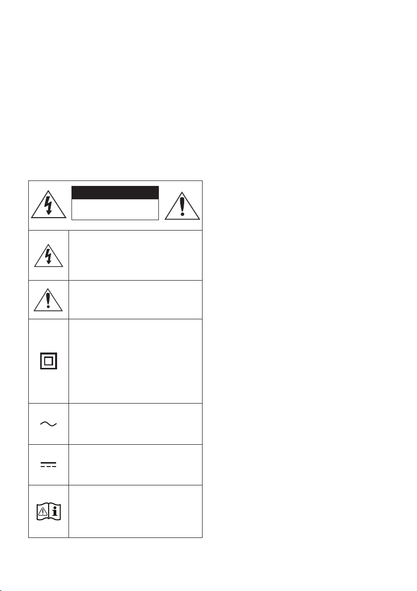
Refer to the table below for an explanation of
symbols which may be on your Samsung product.
CAUTION
RISK OF E LECTRIC S HOCK.
DO NOT OP EN.
This symbol indicates that high voltage
is present inside. It is dangerous to
make any kind of contact with any
internal part of this product.
This symbol indicates that this product
has included important literature
concerning operation and maintenance.
Class II product : This symbol indicates
that it does not require a safety
connection to electrical earth (ground).
If this symbol is not present on a
product with a power cord, the product
MUST have a reliable connection to
protective earth (ground).
WARNING
• To reduce the risk of re or electric shock, do
not expose this appliance to rain or moisture.
CAUTION
• TO PREVENT ELECTRIC SHOCK, MATCH WIDE
BLADE OF PLUG TO WIDE SLOT, FULLY INSERT.
• This apparatus shall always be connected to a
AC outlet with a protective grounding
connection.
• To disconnect the apparatus from the mains,
the plug must be pulled out from the mains
socket, therefore the mains plug shall be
readily operable.
• Do not expose this apparatus to dripping or
splashing. Do not put objects lled with
liquids, such as vases on the apparatus.
• To turn this apparatus of f completely, you
must pull the power plug out of the wall
socket. Consequently, the power plug must
be easily and readily accessible at all times.
AC voltage : This symbol indicates that
the rated voltage marked with the
symbol is AC voltage.
DC voltage : This symbol indicates that
the rated voltage marked with the
symbol is DC voltage.
Caution, Consult instructions for use :
This symbol instruc ts the user to
consult the user manual for fur ther
safety related information.
ENG - ii
PRECAUTIONS
1. Ensure that the AC power supply in your
house complies with the power
requirements listed on the identication
sticker located on the bottom of your
product. Install your product horizontally, on
a suitable base (furniture), with enough
space around it for ventilation (7~10 cm).
Make sure the ventilation slots are not
covered. Do not place the unit on ampliers
or other equipment which may become hot.
This unit is designed for continuous use. To
fully turn off the unit, disconnect the AC plug
from the wall outlet. Unplug the unit if you
intend to leave it unused for a long period of
time.
2. During thunderstorms, disconnect the AC
plug from the wall outlet. Voltage peaks due
to lightning could damage the unit.
3. Do not expose the unit to direct sunlight or
other heat sources. This could lead to
overheating and cause the unit to
malfunction.
4. Protect the product from moisture (i.e.
vases), and excess heat (e.g. a replace) or
equipment creating strong magnetic or
electric elds. Unplug the power cable from
the AC wall socket if the unit malfunctions.
Your product is not intended for industrial
use. It is for personal use only. Condensation
may occur if your product has been stored in
cold temperatures. If transporting the unit
during the winter, wait approximately
2 hours until the unit has reached room
temperature before using.
5. The battery used with this product contains
chemicals that are harmful to the
environment. Do not dispose of the battery
in the general household trash. Do not
expose the battery to excess heat, direct
sunlight, or re. Do not short circuit,
disassemble, or overheat the battery.
Danger of explosion if the battery is replaced
incorrectly. Replace only with the same or
equivalent type.
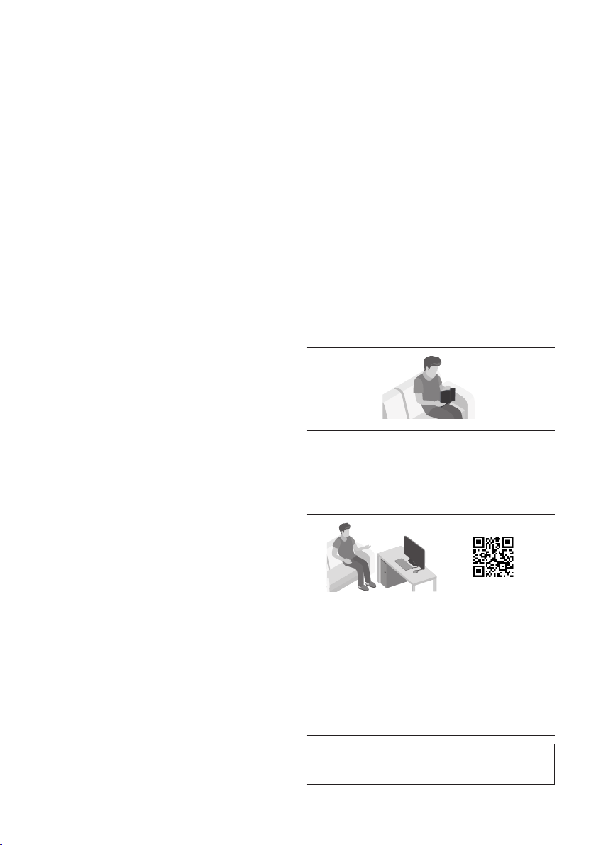
ABOUT THIS MANUAL
The user manual has two parts: this simple paper
USER MANUAL and a detailed FULL MANUAL you
can download.
USER MANUAL
See this manual for safety instructions,
product installation, components,
connections, and product specications.
FULL MANUAL
You can access the FULL MANUAL on
Samsung’s on-line customer support centre by
scanning the QR code. To see the manual on
your PC or mobile device, download the
manual in document format from Samsung’s
website. (http://www.samsung.com/support)
Design and specications are subject to change
without prior notice.
ENG - iii

CONTENTS
01 Checking the Components 2
Inserting Batteries before using the Remote Control (AA batteries X 2) ------------------------- 2
02 Product Overview 3
Front Panel / Top Panel of the Soundbar ------------------------- 3
Bottom Panel of the Soundbar ------------------------- 4
03 Connecting the Soundbar 5
Connecting Electrical Power
Connecting the Soundbar to the Subwoofer
– Automatic connection between the Subwoofer and the Soundbar
– Manually connecting the Subwoofer if automatic connection fails
Connecting an SWA-8500S (Sold Separately) to your Soundbar
-------------------------
-------------------------
-------------------------
-------------------------
-------------------------
04 Connecting to your TV 10
Method 1. Connecting with a Cable
– Connecting a TV using an HDMI Cable
– Connecting using an Optical Cable
Method 2. Connecting Wirelessly
– Connecting a TV via Bluetooth
-------------------------
-------------------------
-------------------------
-------------------------
-------------------------
05 Connecting an External Device 14
Connecting using an HDMI Cable
Connecting using an Optical Cable
-------------------------
-------------------------
06 Connecting a USB Storage Device 16
5
6
6
7
8
10
10
11
12
12
14
15
ENG - iv

07 Connecting a Mobile Device 17
Connecting via Bluetooth
-------------------------
08 Using the Remote Control 21
How to Use the Remote Control
Adjusting the Soundbar volume with a TV remote control
Using the Hidden Buttons (Buttons with more than one function)
Output specications for the different sound effect modes
-------------------------
-------------------------
-------------------------
-------------------------
09 Installing the Wall Mount 26
Installation Precautions
Wallmount Components
-------------------------
-------------------------
10 Software Update 28
How to check the Firmware version
Update Procedure
If UPDATE is not displayed
-------------------------
-------------------------
-------------------------
11 Troubleshooting 30
17
21
24
25
25
26
26
28
29
29
12 Licence 31
13 Open Source Licence Notice 31
14 Important Notes About Service 31
15 SpecicationsandGuide 32
Specications
-------------------------
ENG - v
32
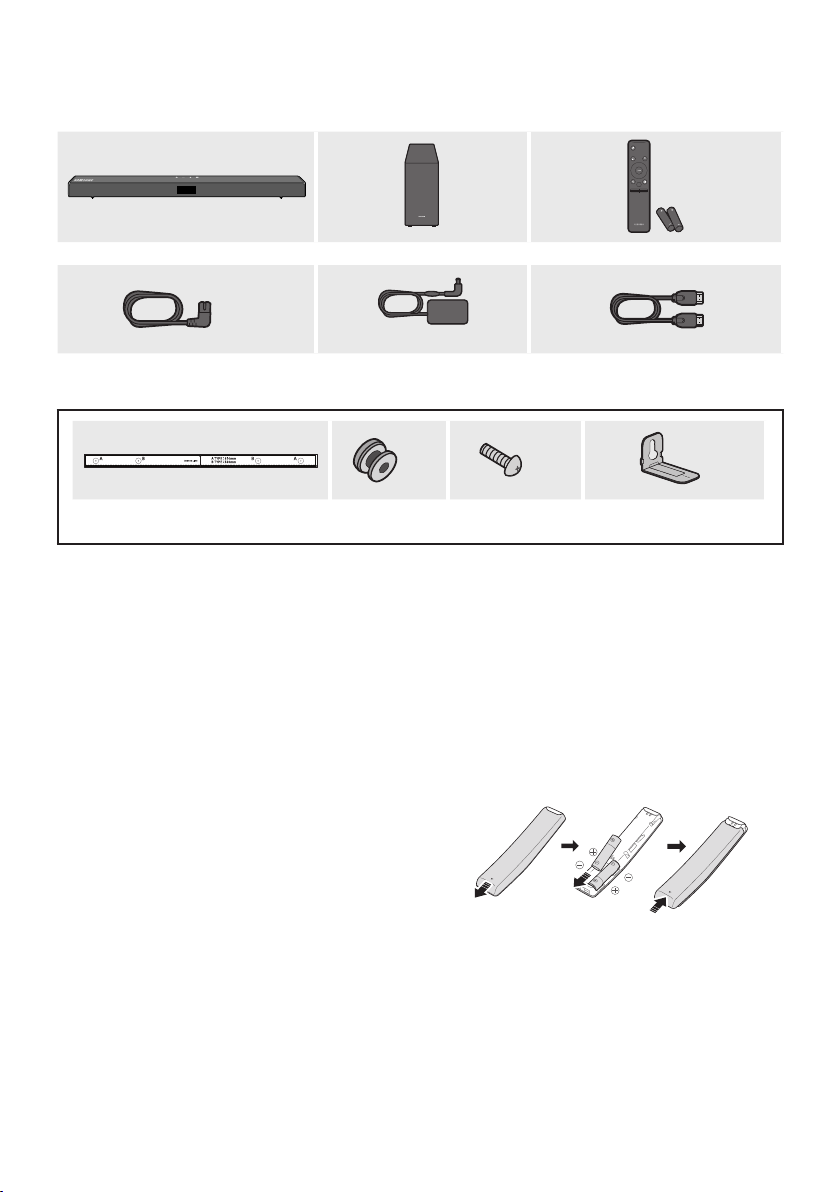
01 CHECKING THE COMPONENTS
Soundbar Main Unit Subwoofer Remote Control / Bat teries
x 2
PAIR
SOUND
MODE
VOL WOOFER
SOUNDBAR
Power Cord
(Subwoofer, Soundbar)
AC/DC Adapter
(Soundbar)
x 2
x 2
HDMI Cable
x 2
Wall Mount Guide Holder-Screw Screw Bracket-Wall Mount
• For more information about the power supply and power consumption, refer to the label attached
to the product. (Label: Bottom of the Soundbar Main Unit)
• To purchase additional components or optional cables, contact a Samsung Service Centre or
Samsung Customer Care.
• Depending on the region, the appearance of the AC plug may differ from the plug displayed above,
or it may be supplied integrated with the AC/DC adapter.
• The appearance of the accessories may differ slightly from the illustrations above.
Inserting Batteries before using the Remote Control (AA batteries X 2)
Slide the back cover in the direction of the arrow
until it is completely removed. Insert 2 AA batteries
(1.5V) oriented so that their polarity is correct. Slide
the back cover back into position.
ENG - 2
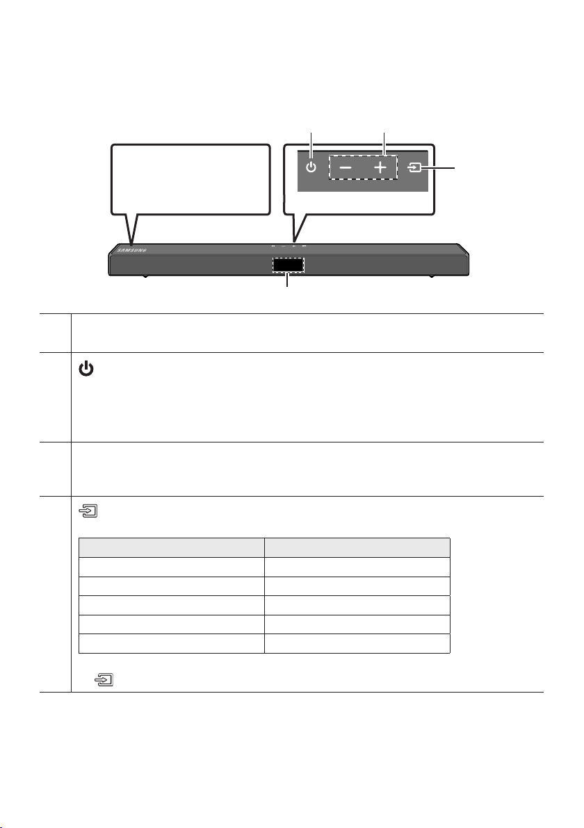
02 PRODUCT OVERVIEW
Front Panel / Top Panel of the Soundbar
Position the product so that
the SAMSUNG logo is
located on the top.
Top Panel
Display
Displays the product’s status and current mode.
(Power) Button
Turns the power on and off.
• Auto Power Down Function
The unit turns off automatically in the following situations:
– In D.IN / HDMI / BT / USB Mode : If there is no audio signal for 20 minutes.
-/+ (Volume) But ton
Adjusts the volume.
• When adjusted, the volume level appears on the Soundbar’s front display.
(Source) But ton
Selects the source input mode.
Input mode Display
Optical Digital input D.IN
ARC (HDMI OUT) input D.IN TV ARC (Auto conversion)
HDMI input HDMI
BLUETOOTH mode BT
USB mode USB
• To turn on “BT PAIRING” mode, change the source to “BT” mode, and then press and hold the
(Source) button for more than 5 seconds.
• When you plug in the AC cord, the power button will begin working in 4 to 6 seconds.
• When you turn on this unit, there will be a 4 to 5 second delay before it produces sound.
• If you want to enjoy sound only from the Soundbar, you must turn off the TV’s speakers in the Audio
Setup menu of your TV. Refer to the owner’s manual supplied with your TV.
ENG - 3
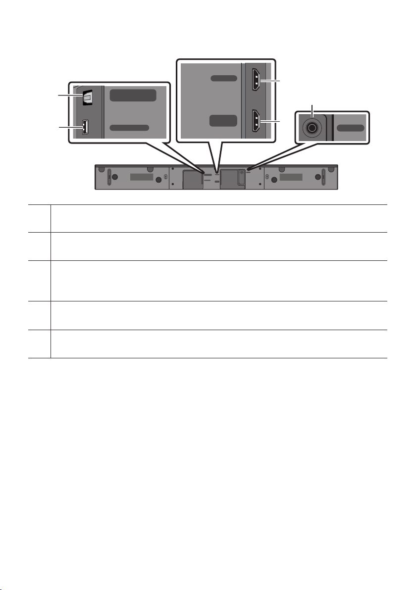
Bottom Panel of the Soundbar
HDMI IN
HDMI
DIGITAL AUD IO IN (OPTIC AL)
Connect to the digital (optical) output of an external device.
USB (5V 0. 5A)
Connect a USB device here to play music les stored on the USB device through the Soundbar.
DIGITAL AUDIO IN
(OPTICAL)
USB (5V 0.5A)
HDMI TO TV
DIGITAL AUDIO IN
HDMI
(OPTICAL)
USB (5V 0.5A)
HDMI TO TV
(ARC)
(ARC)
DC 24V
HDMI
Inputs digital video and audio signals simultaneously using an HDMI cable.
Connect to the HDMI output of an external device.
HDMI TO T V (ARC)
Connect to the HDMI (ARC) jack on a TV.
DC 24V (P ower Supply In)
Connect the AC/DC power adapter.
DC 24V
• When disconnecting the power cable of the AC/DC power adaptor from a wall outlet, pull the plug.
Do not pull the cable.
• Do not connect this unit or other components to an AC outlet until all connections between
components are complete.
ENG - 4
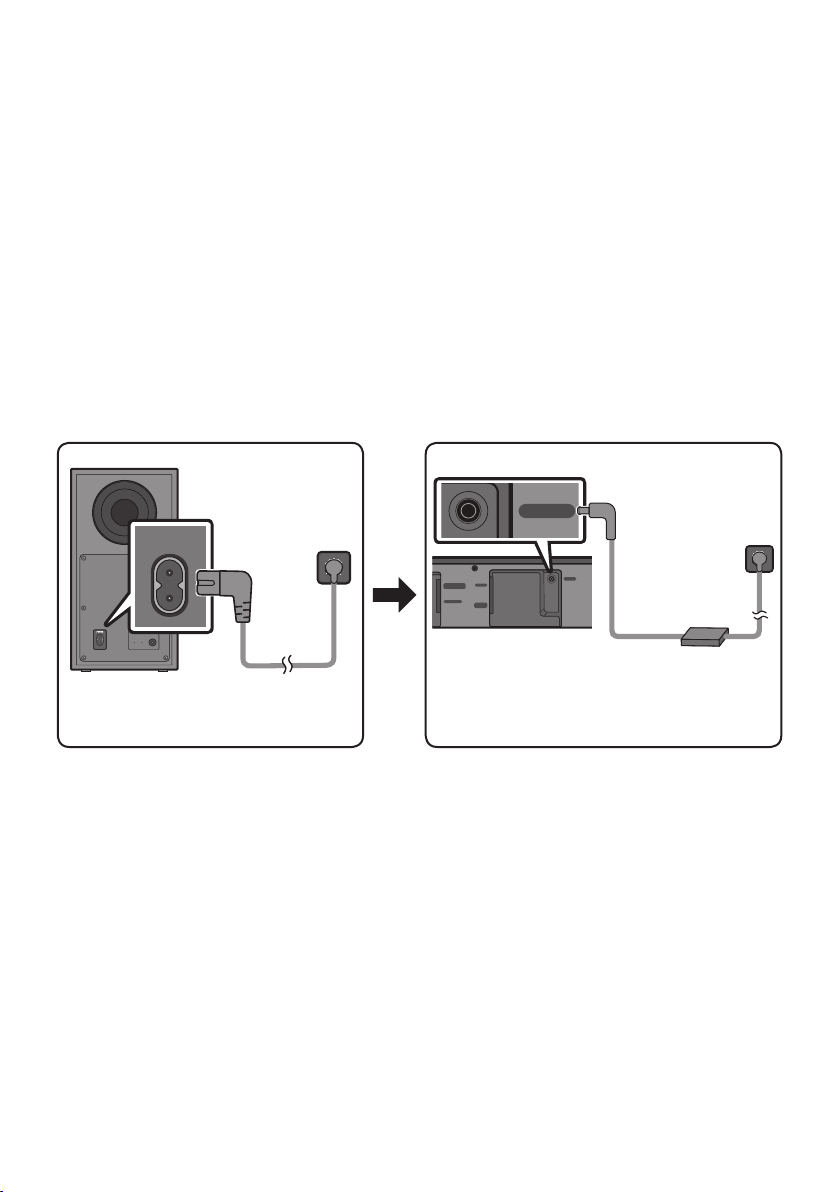
03 CONNECTING THE SOUNDBAR
Connecting Electrical Power
Use the power components to connect the Subwoofer and Soundbar to an electrical outlet in the following
order:
1. Connect the power cord to the Subwoofer.
2. Connect the power output cable to the power adapter, and then to the Soundbar.
3. Connect the power cord to a wall socket.
See the illustrations below.
• For more information about the required electrical power and power consumption, refer to the
label attached to the product. (Label: Bottom of the Soundbar Main Unit)
POWER
Rear of Subwoofer
Power Cord
Connecting
DC 24V
DIGITAL AUDIO IN
HDMI
(OPTICAL)
USB (5V 0.5A)
HDMI TO TV
(ARC)
Bott om of the
Soundbar Main Unit
DC 24V
Power Cord
Connecting
Electric al Power
AC/DC Adapter
Electric al Power
• Make sure to rest the AC/DC Adapter at on a table or the oor. If you place the AC/DC Adapter so
that it is hanging with the AC cord input facing upwards, water or other foreign substances could
enter the Adapter and cause the Adapter to malfunction.
ENG - 5

Connecting the Soundbar to the Subwoofer
When the subwoofer is connected, you can enjoy rich bass sound.
Automatic connection between the Subwoofer and the Soundbar
When you turn the power on after connecting the power cables to the Soundbar and subwoofer, the
subwoofer is automatically connected to the Soundbar.
• When auto pairing is complete, the blue indicators at the rear of the subwoofer turn on.
LED Indicator Lights on the Rear of Subwoofer
LED Status Description Resolution
Successfully connected
(normal operation)
Standby (with the Soundbar
main unit turned off)
Connection failed
-
Check if the power cable attached to the
main Soundbar unit is connected properly
or wait about 5 minutes. If blinking persists,
try manually connecting the subwoofer.
See page 7.
Check if the power cable attached to the
main Soundbar unit is connected properly.
Connect again. See the instructions for
manual connection on page 7.
See the contact information for the
Samsung Service Centre in this manual.
Blue
Red On
Red and
blue
On
Blinking Recovering the connection
Blinking Malfunction
ENG - 6
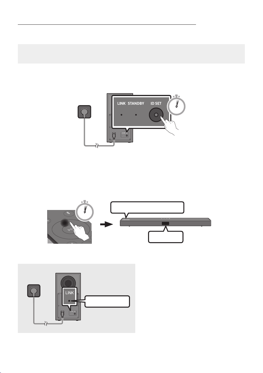
Manually connecting the Subwoofer if automatic connection fails
Before per forming the manual connection procedure below:
• Check whether the power cables for the Soundbar and subwoofer are connected properly.
• Make sure that the Soundbar is turned on.
1. Press and hold ID SET on the rear of the subwoofer for at least 5 seconds.
• The red indicator on the rear of the subwoofer turns off and the blue indicator blinks.
5 Sec
Rear of Subwoofer
2. Press and hold the Up button on the remote control for at least 5 seconds.
• The ID SET message appears on the display of the Soundbar for a moment, and then it
disappears.
• The Soundbar will automatically power on when ID SET is complete.
SAMSU NG logo is on the top
PAIR
5 Sec
3. Check if the LINK LED is solid blue (connection complete).
The LINK LED indicator stops blinking and
glows a solid blue when a connection is
established between the Soundbar and the
Wireless Subwoofer.
Blue is On
ENG - 7
ID SET
NOTES
L
R
• Do not connect the power cord of this product or your TV to a wall outlet until all connections
between components are complete.
• Before moving or installing this product, be sure to turn off the power and disconnect the power cord.
• If the main unit is powered off, the wireless subwoofer will go into stand-by mode and the
STANDBY LED on the rear of the sub-woofer will turn red after blinking in blue several times.
• If you use a device that uses the same frequency (5.8GHz) as the Soundbar near the Soundbar,
interference may cause some sound interruption.
• The maximum transmission distance of the main unit’s wireless signal is about 10 m, but may vary
depending on your operating environment. If a steel-concrete or metallic wall is between the main
unit and the wireless subwoofer, the system may not operate at all because the wireless signal
cannot penetrate metal.
PRECAUTIONS
• Wireless receiving antennas are built into the wireless subwoofer. Keep the unit away from water
and moisture.
• For optimal listening performance, make sure that the area around the wireless subwoofer and the
Wireless Receiver Module (sold separately) is clear of any obstructions.
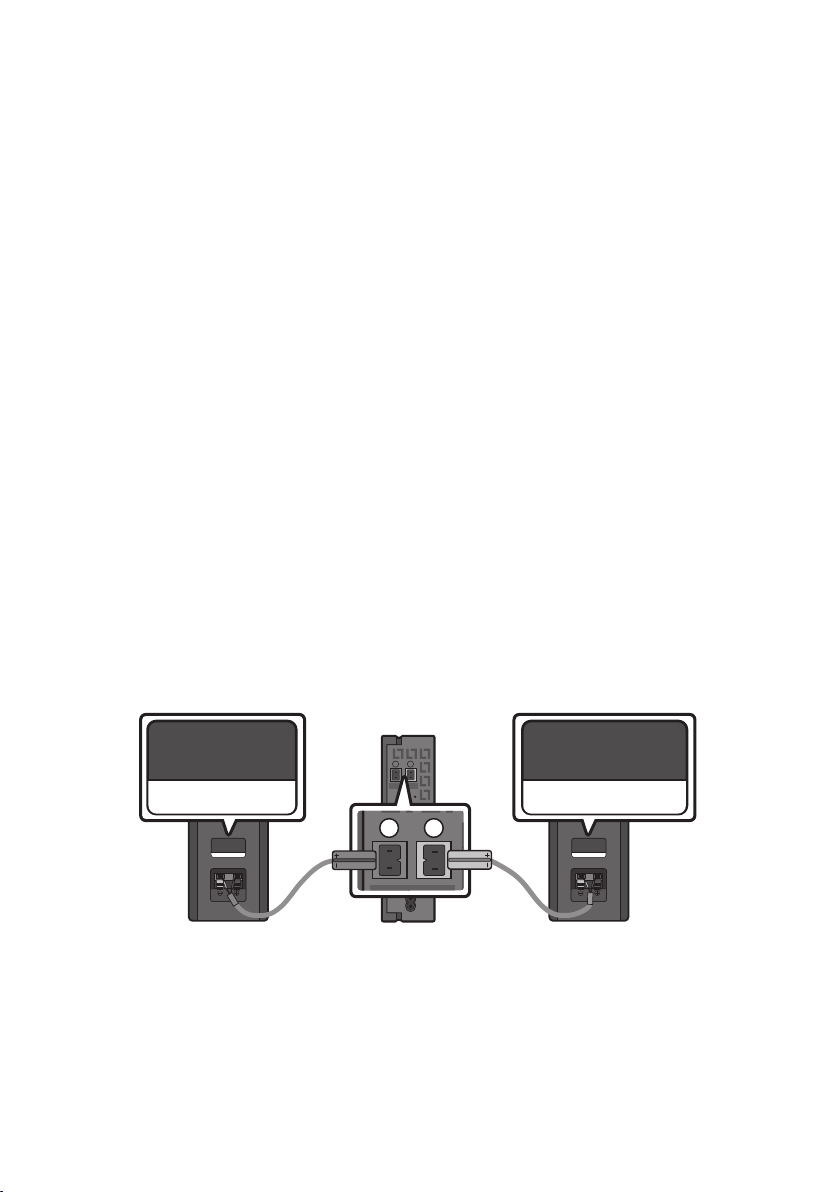
Connecting an SWA-8500S (Sold Separately) to your Soundbar
Expand to true wireless surround sound by connecting the Samsung Wireless Rear Speaker Kit
(SWA-8500S, sold separately) to your Soundbar.
1. Connect the Wireless Receiver Module to 2 Surround Speakers.
– The speaker cables are colour coded.
L
R
SURROUND SPEAKERS OUT
SPEAKER IMPEDANCE : 3Ω
SURROUND-LEFT SURROUND-RIGHT
SURROUND-LEFT
ID SET
POWER
ENG - 8
SURROUND-RIGHT
 Loading...