

Samsung HW-D450 Service Manual
CrystalSurroundAir Track
ModelNameHW-D450
ModelCodeHW-D450/ZA
SERVICE
CrystalSurroundAirTrack
MANUAL
HW-D450
RefertotheservicemanualintheGSPN(seetherearcover)formoreinformation.
1.Precaution
DEVICE
UNDER
TES T
LEAKAGE
CUR RE NT
TES TER
TES T ALL
EXPO SED ME TAL
SU RFACES
2-WIRE COR D
ALSO TE S T WITH
PLUG REVER S ED
(US ING AC
ADAPTER P LUG
AS R EQ UIRED )
EARTH
GR OUND
(RE ADING
SH OULD NOT BE
ABOVE 0.5m A)
FollowthesesafetyinstructionswhileservicingtheESDtopreventdamageandtoprotectagainstpotentialhazards
suchaselectricalshockandX-rays.
1.1.SafetyPrecautions
1)Whenreinstallingthechassisanditsassemblies,besuretorestorealloftheprotectivedevices,includingthecontrol
knobsandthecompartmentcovers.
2)Makesurethattherearenocabinetopeningsthroughwhichpeople(particularlychildren)canmakecontactwith
dangerousinternalcomponents.
3)DesignAlterationWarning:
Neveralteroraddtothemechanicalorelectricaldesignoftheunit.
Example:Donotaddauxiliaryaudioorvideoconnectors.Suchalterationsmightcreateasafetyhazard.
Also,anydesignchangesoradditionswillvoidthemanufacturer’swarranty.
1.Precaution
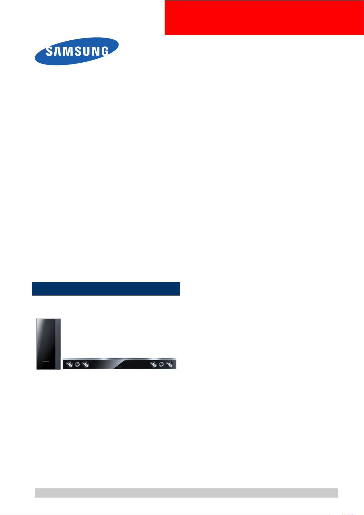
4)LeakageCurrentHotCheckFigure1.1
ACLeakageTest:
WARNING
Donotuseanisolationtransformerduringthistest.Usealeakage-currenttesterorameteringsystemthatcomplies
withAmericanNationalStandardsInstitute(ANSIC101.1,LeakageCurrentforAppliances),andUnderwriters
Laboratories(ULPublicationUL1410,59.7).
Withtheunitcompletelyreassembled,plugtheACcorddirectlyintoa120VACoutlet.Withtheunit’spowerswitched
fromtheONtotheOFFposition,measurethecurrentbetweenaknowngroundandallexposedmetalparts.
KnownGrounds-Earth
KnownMetalparts-screwheads,metalcabinets,etc.
Figure1.1ACLeakageTest
Copyright©1995-2011SAMSUNG.Allrightsreserved.1-1
1.Precaution
Ante nna
Term inal
ohm
Expo s ed
Meta l Pa rt
Ohmmet er
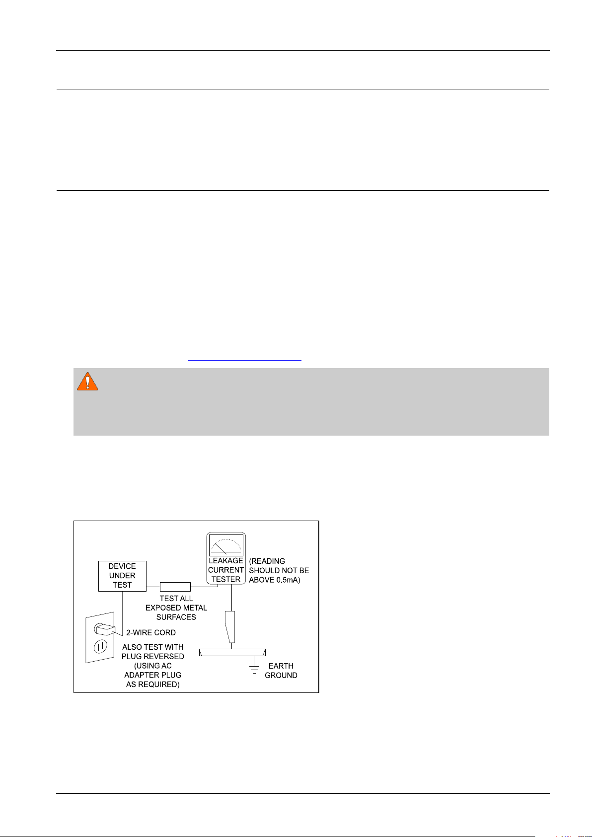
5)InsulationResistanceColdCheck:
(1)Withtheunit’sACplugdisconnectedfromtheACsource,connectanelectricaljumperacrossthetwoACprongs.
(2)SetthepowerswitchtoON.(3)MeasuretheresistancebetweentheshortedACplugandanyexposedmetallicparts.
Example:screwheads,metalcabinets,antennaport,etc.Ifanyoftheexposedmetallicpartshasareturnpathtothe
chassis,themeasuredresistanceshouldbebetween1and5.2megohms.Ifthereisnoreturnpath,themeasured
resistanceshouldbe“innite.”Iftheresistanceisoutsidetheselimits,ashockhazardmightexist.SeeFigure1.2
InsulationResistanceTest
Figure1.2InsulationResistanceT est
6)Components,partsandwiringthatappeartohaveoverheatedorthatareotherwisedamagedshouldbereplacedwith
partsthatmeettheoriginalspecications.Alwaysdeterminethecauseofdamageoroverheating,andcorrectany
potentialhazards.
7)Observetheoriginalleaddress,especiallynearthefollowingareas:Antennawiring,sharpedges,andespeciallytheAC
andhighvoltagepowersupplies.Alwaysinspectforpinched,out-of-place,orfrayedwiring.
Donotchangethespacingbetweencomponentsandtheprintedcircuitboard.ChecktheACpowercordfordamage.
Makesurethatnowiresorcomponentstouchthermallyhotparts.
8)ProductSafetyNotice:
Someelectricalandmechanicalpartshavespecialsafety-relatedcharacteristicswhichmightnotbeobviousfromvisual
inspection.Thesesafetyfeaturesandtheprotectiontheygivemightbelostifthereplacementcomponentdiffersfrom
theoriginal—evenifthereplacementisratedforhighervoltage,wattage,etc.
9)Componentsthatarecriticalforsafetyareindicatedinthecircuitdiagrambyshading,
or.Usereplacement
componentsthathavethesameratings,especiallyforameresistanceanddielectricstrengthspecications.A
replacementpartthatdoesnothavethesamesafetycharacteristicsastheoriginalmightcreateshock,reorother
hazards.
1-2Copyright©1995-2011SAMSUNG.Allrightsreserved.

1.Precaution
1.2.ServicingPrecautions
1)Servicingprecautionsareprintedonthecabinet.Followthem.
2)Alwaysunplugtheunit’sACpowercordfromtheACpowersourcebeforeattemptingto:(a)Removeorreinstallany
componentorassembly,(b)Disconnectanelectricalplugorconnector,(c)Connectatestcomponentinparallelwith
anelectrolyticcapacitor.
3)Somecomponentsareraisedabovetheprintedcircuitboardforsafety.Aninsulationtubeortapeissometimesused.
Theinternalwiringmaybeclampedtopreventcontactwiththermallyhotcomponents.Reinstallallsuchelements
totheiroriginalposition.
4)Afterservicing,alwayscheckthatthescrews,componentsandwiringhavebeencorrectlyreinstalled.
Makesurethattheportionaroundtheservicedparthasnotbeendamaged.
5)ChecktheinsulationbetweenthebladesoftheACplugandaccessibleconductiveparts(examples:metalpanels,
inputterminalsandearphonejacks).
6)InsulationCheckingProcedure:DisconnectthepowercordfromtheACsource.Connectaninsulationresistance
meter(500V)tothebladesoftheACplug.
TheinsulationresistancebetweeneachbladeoftheACplugandaccessibleconductiveparts(seeabove)shouldbe
greaterthan1megohm.
7)NeverdefeatanyoftheB+voltageinterlocks.DonotapplyACpowertotheunit(oranyofitsassemblies)unlessall
solid-stateheatsinksarecorrectlyinstalled.
8)Alwaysconnectatestinstrument’sgroundleadtotheinstrumentchassisgroundbeforeconnectingthepositivelead;
alwaysremovetheinstrument’sgroundleadlast.
CAUTION
Firstreadthe“SafetyPrecautions”sectionofthismanual.Ifsomeunforeseencircumstancecreatesaconictbetweenthe
servicingandsafetyprecautions,alwaysfollowthesafetyprecautions.
Copyright©1995-2011SAMSUNG.Allrightsreserved.1-3

1.Precaution
1.3.PrecautionsforElectrostaticallySensitiveDevices(ESDs)
Somesemiconductor(“solidstate”)devicesareeasilydamagedbystaticelectricity.
SuchcomponentsarecalledElectrostaticallySensitiveDevices(ESDs).
Examplesincludeintegratedcircuitsandsomeeld-effecttransistors.Thefollowingtechniqueswillreducetheoccurrence
ofcomponentdamagecausedbystaticelectricity:
1)Immediatelybeforehandlinganysemiconductorcomponentsorassemblies,draintheelectrostaticchargefromyour
bodybytouchingaknownearthground.Alternatively,wearadischargingwrist-strapdevice.(Besuretoremoveit
priortoapplyingpower–thisisanelectricshockprecaution.)
2)AfterremovinganESD-equippedassembly,placeitonaconductivesurfacesuchasaluminumfoiltoprevent
accumulationofelectrostaticcharge.
3)Donotusefreon-propelledchemicals.ThesecangenerateelectricalchargesthatdamageESDs.
4)Useonlyagrounded-tipsolderingironwhensolderingorunsolderingESDs.
5)Useonlyananti-staticsolderremovaldevice.Manysolderremovaldevicesarenotratedas“anti-static”(thesecan
accumulatesufcientelectricalchargetodamageESDs).
6)DonotremoveareplacementESDfromitsprotectivepackageuntilyouarereadytoinstallit.
MostreplacementESDsarepackagedwithleadsthatareelectricallyshortedtogetherbyconductivefoam,aluminum
foilorotherconductivematerials.
7)ImmediatelybeforeremovingtheprotectivematerialfromtheleadsofareplacementESD,touchtheprotectivematerial
tothechassisorcircuitassemblyintowhichthedevicewillbeinstalled.
8)MinimizebodymotionswhenhandlingunpackagedreplacementESDs.Motionssuchasbrushingclothestogether,or
liftingafootfromacarpetedoorcangenerateenoughstaticelectricitytodamageanESD.
1-4Copyright©1995-2011SAMSUNG.Allrightsreserved.

2.ProductSpecication
2.1.ProductFeature
■HW-D550/HW-D570
•310W(80Wx2+150W)
•2.1CH,Wireless(active)
-DD,DTS
-1Analog/2Opticals
-HDMIOUT1/HDMIIN2
-SmartVolumeII
-VirtualSurround(Music/News/Movie/Drama/Game/Sports/Pass)
-3DSOUND
-2way3spk
2.ProductSpecication
■HW-D450
•280W(80Wx2+120W)
•2.1CH,Wireless(active)
-DD,DTS
-1Analog/2Opticals
-SmartVolumeII
-VirtualSurround(Music/News/Movie/Drama/Game/Sports/Pass)
-3DSOUND
-2way3spk
■HW-D350
•120W(60Wx2)
•2.1CH,Wireless(active)
-DD,DTS
-1Analog/2Opticals
-SmartVolumeII
-VirtualSurround(Music/News/Movie/Drama/Game/Sports/Pass)
-3DSOUND
-2way3spk
Copyright©1995-2011SAMSUNG.Allrightsreserved.2-1
2.ProductSpecication
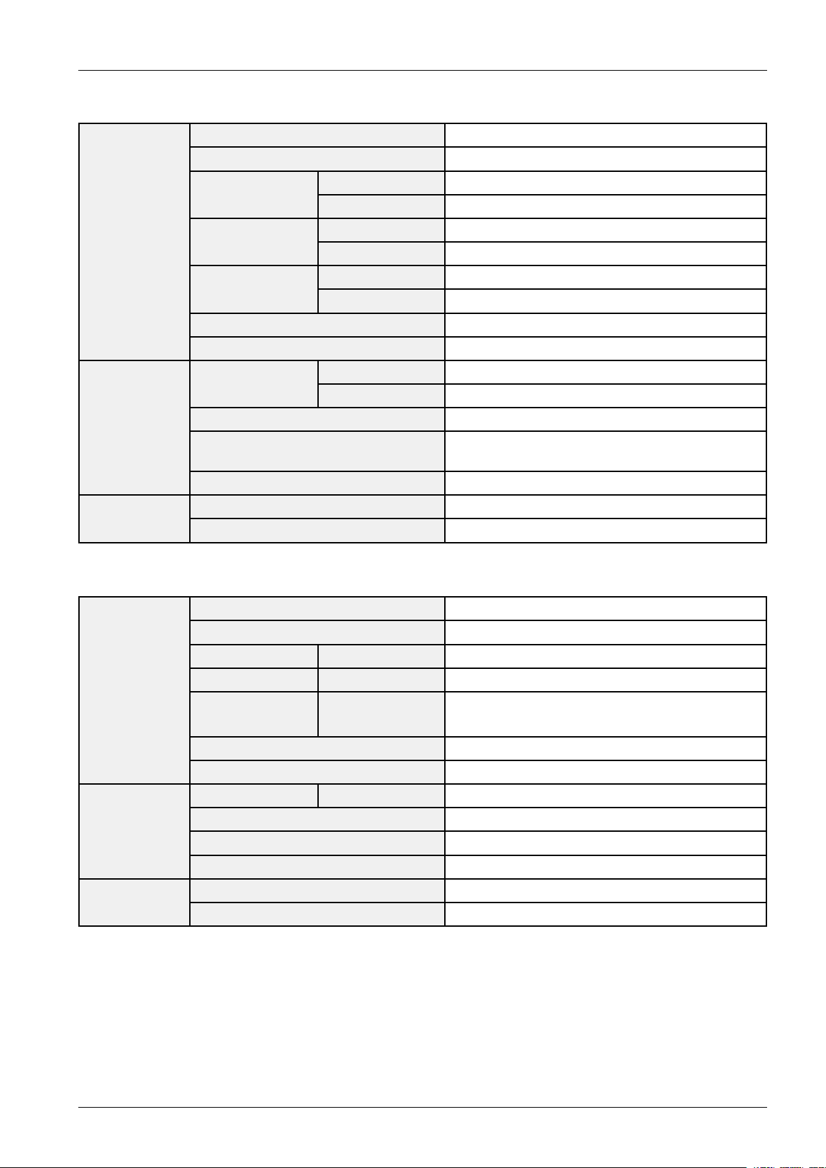
2.2.Specications
■HW-D550/HW-D570BasicSpecication
PowersupplyAC120V ,60Hz
Standbypowerconsumption0.75W
Powerconsumption
General
AMPLIFIER
FREQUENCY
RESPONSE
Weight
Dimensions
(WxHxD)
Operatingtemperaturerange+41°Fto+95°F
Operatinghumidityrange10%to75%
Ratedoutputpower
Inputsensitivity/Impedance570mV/20KΩ
S/Nratio(analoginput)70dB
Separation(1kHz)70dB
Analoginput20Hz~20kHz(±3dB)
Digitalinput/48kHzPCM20Hz~20kHz(±3dB)
Mainunit45W
Subwoofer20W
Mainunit4.41Ibs
Subwoofer12.01Ibs
Mainunit41.65x3.15x1.58inches
Subwoofer6.89x13.78x11.61inches
Mainunit80W/CH,4Ω,THD=10%,1kHz
Subwoofer150W,3Ω,THD=10%,100Hz
2-2Copyright©1995-2011SAMSUNG.Allrightsreserved.
■HW-D450BasicSpecication
2.ProductSpecication
PowersupplyAC120V ,60Hz
Standbypowerconsumption0.75W
AMPLIFIER
FREQUENCY
RESPONSE
■HW-D350BasicSpecication
Powerconsumption
General
Weight
Dimensions
(WxHxD)
Operatingtemperaturerange+41°Fto+95°F
Operatinghumidityrange10%to75%
Ratedoutputpower
Inputsensitivity/Impedance570mV/20KΩ
S/Nratio(analoginput)70dB
Separation(1kHz)70dB
Analoginput20Hz~20kHz(±3dB)
Digitalinput/48kHzPCM20Hz~20kHz(±3dB)
Mainunit45W
Subwoofer20W
Mainunit5.01Ibs
Subwoofer12.01Ibs
Mainunit37.66x3.62x1.77inches
Subwoofer6.89x13.78x11.61inches
Mainunit80W/CH,4Ω,THD=10%,1kHz
Subwoofer120W,4Ω,THD=10%,100Hz
PowersupplyAC120V ,60Hz
Standbypowerconsumption0.75W
PowerconsumptionMainunit45W
General
AMPLIFIER
FREQUENCY
RESPONSE
WeightMainunit5.01Ibs
Dimensions
(WxHxD)
Operatingtemperaturerange+41°Fto+95°F
Operatinghumidityrange10%to75%
RatedoutputpowerMainunit80W/CH,4Ω,THD=10%,1kHz
Inputsensitivity/Impedance570mV/20KΩ
S/Nratio(analoginput)70dB
Separation(1kHz)70dB
Analoginput20Hz~20kHz(±3dB)
Digitalinput/48kHzPCM20Hz~20kHz(±3dB)
Mainunit37.66x3.62x1.77inches
Copyright©1995-2011SAMSUNG.Allrightsreserved.2-3
2.ProductSpecication
2.3.SpecicationsAnalysis
OutputPower
Compatible
DVD(Video)
ModelName
Photo
RMS(10%THD),
REF:1ch
OutputPower
(ch)
DiscPlaybackN/AN/AN/AN/A
Media
iPodDock(select
regionsonly)
WirelessReadyXXXX
USBHOSTXXXX ExtraFeatures
BluetoothXXXX
ProgressiveScan
(NT/PAL)
VirtualSurroundOOOO
HW-D550
HW-D570
310W280W120W280W
80Wx2+150W80Wx2+150W60Wx280Wx2+120W
XXXX
XXXX
HW-D450HW-D350HW-C450
3DSoundOOOX
DSP
AudioIn/Out
OpticalJackIn(DigitalIn)O(2)O(2)O(2)O(2)
Headphone
ASCXXXX
SmartV olumeSmartV olumeIISmartV olumeIISmartV olumeIISmartV olumeII
AudioUpscaleXXXX
PowerBassXXXX
DolbyDigital/
Plus
DolbyT rueHDN/AN/AN/AN/A AudioDecoding
DTS/DTS-HD
(HR/MA)
ComponentOutXXXX
HDMIOut(CEC)1XXX Video
HDMIInput2XXX
MiniJackAudio
In
RCAInputXXXX
HeadphoneJack
(3.5Φ)
DolbyDigitalDolbyDigitalDolbyDigitalDolbyDigital
DTSDTSDTSDTS
AUX1(3.5φ)AUX1(3.5φ)AUX1(3.5φ)AUX1(3.5φ)
XXXX
Tuner
2-4Copyright©1995-2011SAMSUNG.Allrightsreserved.
FMXXXX
PresetMemory15151515
2.ProductSpecication
ModelName
Photo
Speaker
TIP
O:FeatureIncluded,X:NotIncluded
Type(Sat/T allboy)
Active(Powered)
S/W
HW-D550
HW-D570
InternalType
(MainFrame
Built-InType)
2way3spk
HW-D450HW-D350HW-C450
InternalType
(MainFrame
Built-InType)
2way3spk
InternalType
(MainFrame
Built-InType)
2way3spk
WirelessActiveWirelessActiveXWirelessActive
InternalType
(MainFrame
Built-InType)
2way3spk
Copyright©1995-2011SAMSUNG.Allrightsreserved.2-5
2.ProductSpecication
POWER
TV POWER
AUDIO
MUTE
TV INFO
AUTO
POWER
AV SYNC
AH59-02330A
VOL
TV
CH
SOUND
MODE
3D
SOUND
S.VOL
INPUT
SELECT
DIMMER
S/W LEVEL
HDMISPK CONTROL
DRC
2.4.Accessories
2.4.1.SuppliedAccessories
AccessoriesItemItemcodeRemark
RemoteControlAH59–02330A
Bracket-WallMountAH61-02952A
FerriteCore
(ForSubwooferpower
3301-000144
cable1EA)
Batteries(AAAsize)4301-000116
OpticalCableAH39-00925B
AudioCableAH39-01077A
User’sManualAH68-02334D
LocalSamsungDealer
2-6Copyright©1995-2011SAMSUNG.Allrightsreserved.
3.Disassembly&Reassembly
3.1.HW-D550/HW-D570Disassembly&Reassembly
3.Disassembly&Reassembly
CAUTION
•Becarefultofollowthedisassemblysequence
describedinthemanual.Otherwise,theproductmay
bedamaged.
•Besuretocarefullyreadandunderstandthesafety
instructionsbeforeperforminganyworkastheIC
chipsonthePCBarevulnerabletostaticelectricity.
•Inordertoassemblereversetheorderofdisassembly.
1.Unfasten13screwsontheRear.
:BH,+,-,B,M3,L10,ZPC(BLK)
CAUTION
Becarefulnottomakeanyscratchesasyouremove
them.
2.RemoveCoverJack,CoverHDMI.
5.Unfasten6screwsonthefront.
:BH,+,-,B,M3,L10,ZPC(SIL VER)
6.DisconnectFPCwire3eachandSPKwire2ea.
7.RemoveASSY -PCB-MAINandASSY-PCB-SMPS.
8.Unfasten1screwontheRear.
:BH,+,-,B,M3,L6,ZPC(SIL VER)
3.RemoveACCord.
4.RemoveCoverRear.
Copyright©1995-2011SAMSUNG.Allrightsreserved.3-1
9.RemoveWIRELESSTXPCB.

3.Disassembly&Reassembly
10.Unfasten2screwsonthefront.
:BH,+,-,B,M3,L6,ZPC(SIL VER)
11.LoosenhooksformASSYSHIELDPCBandRemove
ASSY-PCB-VFD.
12.LoosenhooksformASSYSHIELDPCBandRemove
ASSY-PCB-VFD.
13.DetachSHEET -BUTTONfromAssy-COVER-FRONT .
14.RemoveASSY -SPKRIGHT,ASSY-SPKLEFT.
3-2Copyright©1995-2011SAMSUNG.Allrightsreserved.
3.2.HW-D450/HW-D350Disassembly&Reassembly
AMP-PCB
SMPS-PCB
3.Disassembly&Reassembly
CAUTION
•Becarefultofollowthedisassemblysequence
describedinthemanual.Otherwise,theproductmay
bedamaged.
•Besuretocarefullyreadandunderstandthesafety
instructionsbeforeperforminganyworkastheIC
chipsonthePCBarevulnerabletostaticelectricity.
•Inordertoassemblereversetheorderofdisassembly.
1.V erticalTypeStanding
2.Removethe11screwsfromthebottomof
CABINET-REAR.
:BH,+,B,M3,L10,ZPC(BLK),SWRCH18A
CAUTION
5.AfterdisconnectingthePowercord,Liftthe
Cabinet-Rearupcompletely.
6.Separate3cable(FFCCable)fromAMPPCB.
7.Separate2SPKWiresfromAMPPCB
Becarefulnottomakeanyscratchesasyouremove
them.
3.RemovetheJACK-COVERfromtheRearCabinet.
4.LifttheCABINET-REARuptoseparatePowerCord.
8.SeparatetheconnectionbetweenSMPSPCB&
PCB.
9.Remove6screws.
:BH,+,-,B,M3,L10,ZPC(WHT),SWRCH18A,
10.RemovethescrewandseparateWirelessModule.
:BH,+,-,B,M3,L6,ZPC(WHT),SWRCH18A,RF
Copyright©1995-2011SAMSUNG.Allrightsreserved.3-3

3.Disassembly&Reassembly
11.Separatethechassisfromthefrontcover.
12.SeparatetheVFDAss’y.
13.RemoveASSY -SPKRIGHT,ASSY-SPKLEFT.
3-4Copyright©1995-2011SAMSUNG.Allrightsreserved.
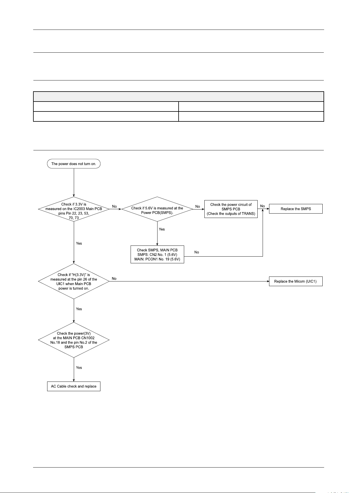
4.Troubleshooting
Ye s
Ch eck if 5.6V is m ea su re d a t the
Po wer P CB(SMP S ).
Ch eck SM PS , MAIN P CB
SMPS : CN 2 No . 1 (5. 6V)
MAIN: PC ON1 No. 19 (5.6V)
No
Ye s
The powe r doe s n ot tu rn on.
AC Cab le ch ec k a nd re place
Ye s
Ye s
Check if “H(3.3V)” is
me asu red a t the pin 2 6 o f the
UIC1 wh e n Ma in PCB
power is turn ed on .
Re place the Micom (UIC1)
Check if 3.3 V is
me asu red on the IC20 03 Main PCB
pins Pin 22 , 23 , 53 ,
70, 73
No
No
Check th e po wer circu it of
SMPS PCB
(Check th e ou tputs of TRANS )
No
Re place the S MPS
Check the po we r(3V)
at the MAIN PC B CN1 002
No.1 8 an d the pin No.2 o f the
SMPS PC B
No
4.1.CheckpointsbyErrorMode
V oltage/DIV1V/div
TIME/DIV500ms/div
4.1.1.NoPower
4.Troubleshooting
OscilloscopeSettingV alues
Copyright©1995-2011SAMSUNG.Allrightsreserved.4-1
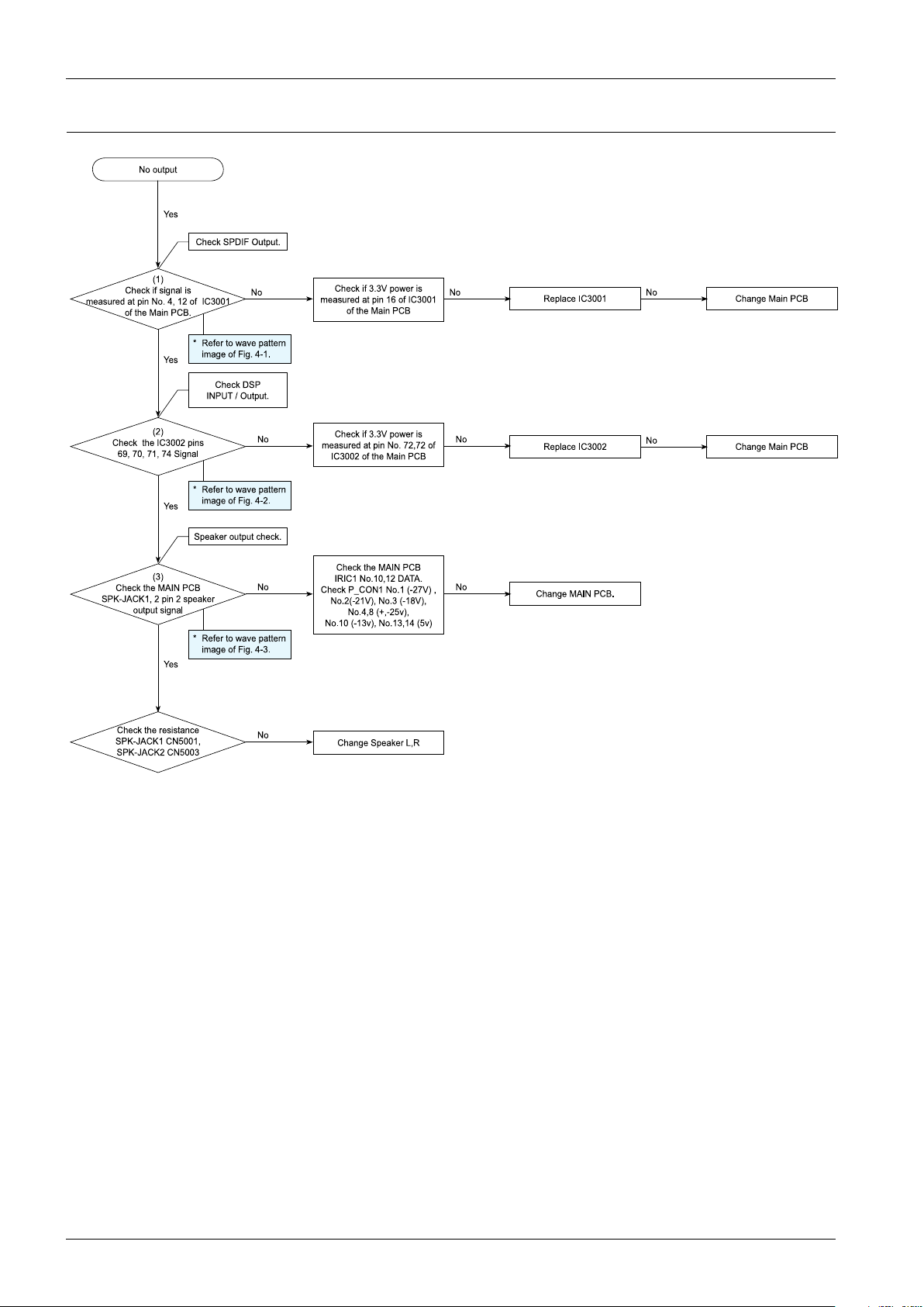
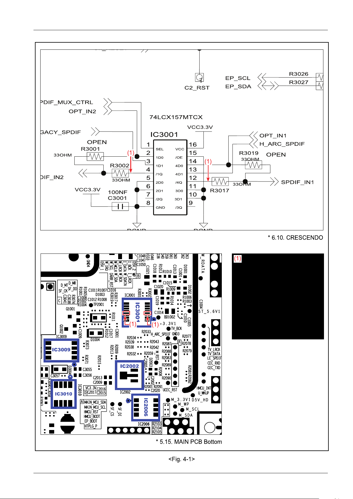
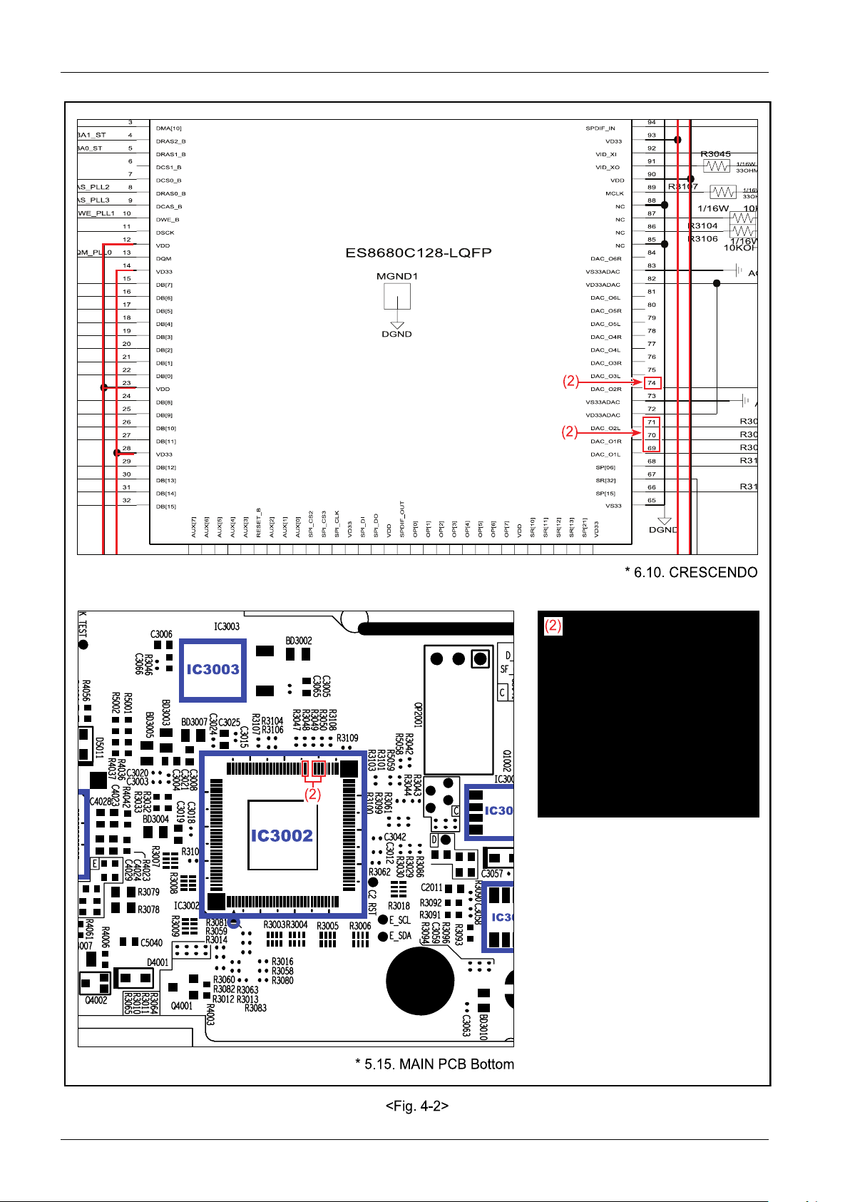
4.Troubleshooting
(1)
Che ck if sign al is
measured at p in No. 4, 12 o f IC3001
of the Main P CB.
Yes
Che ck if 3.3 V powe r is
measured at pin 1 6 of IC300 1
of the Main P CB
No
No o utput
Yes
(2)
Che ck th e IC30 02 pins
69, 70, 71 , 7 4 S igna l
No
Che ck the MAIN PC B
IRIC1 No .10,12 DATA.
Che ck P_ CON1 No.1 (-27V) ,
No.2 (-21V), No.3 (-18V),
No.4 ,8 (+,-25 v),
No.1 0 (-13v), N o.13, 14 (5v)
Che ck SP DIF Ou tput.
Che ck DS P
INPUT / Ou tput.
Cha nge Sp ea ker L,R
No
(3)
Che ck th e MAIN PC B
SP K-JACK1, 2 pin 2 sp e ake r
output sig na l
Speaker outp ut ch eck.
* Re fer to wa ve pa ttern
image of Fig. 4-1 .
* Re fer to wa ve pa ttern
image of Fig. 4-2 .
* Re fer to wa ve pa ttern
image of Fig. 4-3 .
Che ck th e re sis tanc e
SP K-JACK1 CN500 1,
SP K-JACK2 CN500 3
No
No
No
No
Che ck if 3.3 V powe r is
measured at pin N o. 72,72 of
IC3002 o f the Main P CB
Re place IC300 1
No
Cha nge Main P CB
Re place IC300 2
No
Cha nge Main P CB
Cha nge MAIN PC B.
Yes
Yes
4.1.2.NoSoundOutput
4-2Copyright©1995-2011SAMSUNG.Allrightsreserved.
33OHM
33 OHM
33 OHM
OPE N
33OHM
OPE N
VCC3.3 V
VCC3. 3V
74 LCX157 MTCX
10 0NF
TP
C2_RST
IC3001
R3001
R3019
C3001
R3017
R3002
R3 02 7
R3 02 6
SPD IF_IN1
OP T_ IN2
EP_SDA
H_ARC_S PD IF
OP T_ IN1
CII_RESET
EP_SCL
98
7
6
5
4
3
2
16
15
14
13
12
11
10
1
SEL
/OE
GND
/2Q 3D1
/3Q
2D1
1D0
3D0
2D0
4D1
4D0
/4Q
/1Q
1D1
VCC
* 6.10 . CRES CENDO
IC300 9
IC3001
IC301 0
IC2002
IC20 0 6
* 5.15. MAIN P CB Bottom
<Fig. 4 -1>
(1)
(1)
(1)
(1)
(1)
4.Troubleshooting
Copyright©1995-2011SAMSUNG.Allrightsreserved.4-3
4.Troubleshooting
DGND
1/16W
33OHM
1/16W
33OHM
DGND
AGND
10KO HM
1/16 W
ES868 0C 1 28 -LQF P
1/16 W
10KO HM
AGND
R31 09
R31 08
R31 07
R31 06
R31 04
R30 50
R30 49
R30 48
R30 45
65
MGND1
94
93
92
91
90
9
89
88
87
86
85
84
83
82
81
80
8
79
78
77
76
75
74
73
72
71
70
7
69
68
67
66
6
5
4
32
31
30
3
29
28
27
26
25
24
23
22
21
20
19
18
17
16
15
14
13
12
11
10
DCS0_ B
DWE_B
DAC_O4L
DAC_O4R
DAC_O5L
DAC_O5R
LINE_IN_R
LINE_IN_L
LINE_IN_R
DB[9]
DB[10]
DB[11]
VD33
DB[12]
DB[13]
DB[14]
DB[15]
AUX[7]
AUX[6]
AUX[5]
AUX[4]
AUX[3]
RESET_B
AUX[2]
AUX[1]
SR[12 ]
SR[13 ]
SP [21]
VD33
VS33
SP[15]
SR[32]
SP[06]
DAC_O1L
DAC_O1R
DAC_O2L
VD33ADAC
VS33ADAC
DAC_O2R
DAC_O3L
DAC_O3R
OP[2]
OP[3]
OP[4]
OP[5]
OP[6]
OP[7]
VDD
SR[10 ]
SR[11 ]
DMA[0]
DMA[10]
DRAS2_B
DRAS1_B
DCS1_ B
DRAS0_B
DCAS_B
DSCK
VDD
DQM
VD33
DB[7]
DB[6]
DB[5]
DB[4]
DB[3]
DB[2]
DB[1]
DB[0]
VDD
DB[8]
AUX[0]
DAC_O6L
VD33ADAC
VS33ADAC
DAC_O6R
NC
NC
NC
NC
MCLK
VDD
VID_XO
VID_XI
VD33
SPDIF _IN
VD33PLL
LINE_IN_L
LINE_IN_R
LINE_IN_L2
SP I_CS2
SP I_CS3
SP I_CLK
VD33
SP I_DI
SP I_DO
VDD
SP DIF_OUT
OP[0]
OP[1]
* 6.10. CRES CENDO
IC3002
IC3003
IC300
IC3010
* 5.15. MAIN P CB Bottom
<Fig. 4 -2>
(2)
(2)
(2)
(2)
4-4Copyright©1995-2011SAMSUNG.Allrightsreserved.
 Loading...