

Samsung HT-TZ515T-XAA User Manual
QUESTIONS OR COMMENTS?
COUNTRY CALL OR VISIT US ONLINE AT WRITE
IN THE US
1-800-SAMSUNG
(7267864)
www.samsung.com/us
Samsung Electronics America, Inc.
105 Challenger Road Ridgefield Park,
NJ 07660-0511
Code No. AH68-02048J (0.0)

Digital Home
Theater System
user manual
imagine the possibilities
Thank you for purchasing this Samsung product.
To receive more complete service,
please register your product at
www.samsung.com/global/register
HT-TZ515

2
features
Playback of many disc types
The HT-TZ515 allows you to play back various discs, including DVD-AUDIO, DVD-VIDEO, CD, MP3-CD, WMA-CD,
DivX, CD-R/RW, and DVD±R/RW.
DVD-Audio compatible
Experience the super high-quality audio performance of DVD-Audio. The on-board 24-bit/192kHz DAC enables this player to
deliver exceptional sound quality in terms of dynamic range, low-level resolution and high-frequency detail.
USB Host support
You can enjoy media files such as pictures, movies and music saved on an MP3 player, digital camera or USB
memory stick by connecting the storage device to the USB port of the Home Theater.
Dolby Pro Logic II
Dolby Pro Logic II is a form of multi-channel audio signal decoding technology that improves upon existing Dolby Pro
Logic.
DTS (Digital Theater Systems)
DTS is an audio compression format developed by Digital Theater Systems Inc. It delivers full-frequency 5.1 channel
sound.
TV Screen Saver Function
If the main unit remains in Stop mode for 3 minutes, the Samsung logo appears on the TV screen.
The HT-TZ515 will automatically switch to the Power Saving mode after 20 minutes in the Screen Saver mode.
Power Saving Function
The HT-TZ515 will automatically shut off after 20 minutes in Stop mode.
Customized TV Screen Display
The HT-TZ515 allows you to select your favorite image during JPEG or DVD playback and set it as your background
wallpaper.
Anynet+ (HDMI-CEC) Function
Anynet+ is a function that can be used to operate the main unit using a Samsung TV remote control, by connecting the
Home Theater to a SAMSUNG TV using an HDMI Cable. (This is only available with SAMSUNG TV's that support
Anynet+.)
iPod support
You can enjoy music files by your connecting iPod to the home theater with the supplied iPod dock.
Wireless receiver amplifier
Samsung ’s rear- channel wireless module does away with cables running between your DVD receiver and
rear- channel speakers. Instead, the rear speakers connect to a compact wireless module that communicates with your
DVD receiver.
Optional XM radio
You can connect an optional XM Radio Reciever and Antenna for playback through this Home theater.
AV SYNC Function
Video may lag behind the audio if the unit is connected to a digital TV.
To compensate for this, you can adjust the audio delay time to sync up with the video.
3
ENG
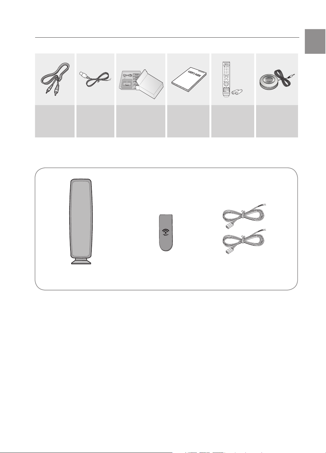
WHAT’S INCLUDED
Check for the supplied accessories below.
Video Cable
(AH39-40001V)
FM Antenna
( AH42-00017A )
iPod Dock Package
( AH97-02650A )
User's Manual
( AH68-02048J )
Remote Control
( AH59-01907F )
/ Batteries (AAA size)
( 4301-000116 )
ASC microphone
( AH30-00099A )
SWA-4000
Wireless Receiver Module TX Card
(AH81-04177J)
Speaker Cable (2EA)
(AH81-02137A)

4
safety information
SAFETY WARNINGS
TO REDUCE THE RISK OF ELECTRIC SHOCK, DO NOT REMOVE THE COVER(OR BACK). NO USER-SERVICEABLE PARTS ARE INSIDE. REFER SERVICING TO QUALIFIED SERVICE PERSONNEL.
CAUTION
RISK OF ELECTRIC SHOCK
DO NOT OPEN
The lighting flash and Arrowhead within
Triangle Is a warning sign alerting you of
dangerous voltage inside the product
CAUTION: TO REDUCE THE RISK OF
ELECTRIC SHOCK, DO NOT REMOVE
COVER (OR BACK) NO USER SERVICEABLE
PARTS INSIDE. REFER SERVICING TO
QULAIFIED SERVICE PERSONNEL.
The explanation point within the triangle is a
warning sign alerting you of important
instructions accompanying the product.
WARNING
To reduce the risk of fire or electric shock, do not expose this appliance to rain or moisture.
To prevent injury, this apparatus must be securely attached to the floor/wall in accordance with the installation instructions.
If this power supply is used at 240V ac, a suitable plug adapter should be used.
CAUTION
Apparatus shall not be exposed to dripping or splashing and no objects filled with liquids, such as vases, shall be placed on the apparatus.
The Mains plug is used as a disconnect device and shall stay readily operable at any time.
This product satisfies FCC regulations when shielded cables and connectors are used to connect the unit to other equipment. To prevent
electromagnetic interference with electric appliances, such as radios and televisions, use shielded cables and connectors for connections.
FCC NOTE (for U.S.A):
This equipment has been tested and found to comply with the limits for a Class B digital device, pursuant to Part 15 of the FCC Rules. These limits
are designed to provide reasonable protection against harmful interference in a residential installation.
This equipment generates, uses and can radiate radio frequency energy and, if not installed and used in accordance with the instructions, may cause
harmful interference to radio communications. However, there is no guarantee that interference will not occur in a particular installation.
If this equipment does cause harmful interference to radio or television reception, which can be determined by turning the equipment off and on, the
user is encouraged to try to correct the interference by one or more of the following measures:
Reorient or relocate the receiving antenna.
Increase the separation between the equipment and receiver.
Connect the equipment into an outlet on a circuit different from that to which the receiver is connected.
Consult the dealer or an experienced radio/TV technician for help.
Caution : FCC regulations state that any unauthorized changes or modifications to this equipment may void the user's authority to operate it.
Important Safety Instructions
Read these operating instructions carefully before using the unit. Follow all the safety instructions listed below. Keep these operating instructions
handy for future reference.
~
~
~
~
~
~
~
~
~
CLASS 1 LASER PRODUCT
This Compact Disc player is classified as a CLASS 1 LASER product.
Use of controls, adjustments or performance of procedures other than
those specified herein may result in hazardous radiation exposure.
CAUTION :
INVISIBLE LASER RADIATION WHEN OPEN AND INTERLOCKS DEFEATED,
AVOID EXPOSURE TO BEAM.
CLASS 1 LASER PRODUCT
KLASSE 1 LASER PRODUKT
LUOKAN 1 LASER LAITE
KLASS 1 LASER APPARAT
PRODUCTO LASER CLASE 1
1) Read these instructions.
2) Keep these Instructions.
3) Heed all warnings.
4) Follow all instructions.
5) Do not use this apparatus near water.
6) Clean only with dry cloth.
7) Do not block any ventilation openings. Install in accordance with the
manufacturer's instructions.
8) Do not install near any heat sources such as radiators, heat
registers, stoves, or other apparatus (including amplifiers) that
produce heat.
9) Do not defeat the safety purpose of the polarized or grounding-type
plug. A polarized plug has two blades with one wider than the other.
A grounding type plug has two blades and a third grounding prong.
The wide blade or the third prong are provided for your safety. If the
provided plug does not fit into your outlet, consult an electrician for
replacement of the obsolete outlet.
10) Protect the power cord from being walked on or pinched
particularly at plugs, convenience receptacles, and the point where
they exit from the apparatus.
11) Only use attachment/accessories
specified by the manufacturer.
12) Use only with the cart, stand, tripod,
bracket, or table specified by the
manufacturer, or sold with the apparatus.
When a cart is used, use caution when
moving the cart/apparatus combination
to avoid injury from tip-over.
13) Unplug this apparatus during lightning storms or when unused for
long periods of time.
14) Refer all servicing to qualified service personnel. Servicing is
required when the apparatus has been damaged in any way, such
as power-supply cord or plug is damaged, liquid has been spilled
or objects have fallen into the apparatus, the apparatus has been
exposed to rain or moisture, does not operate normally, or has
been dropped.
5
ENG
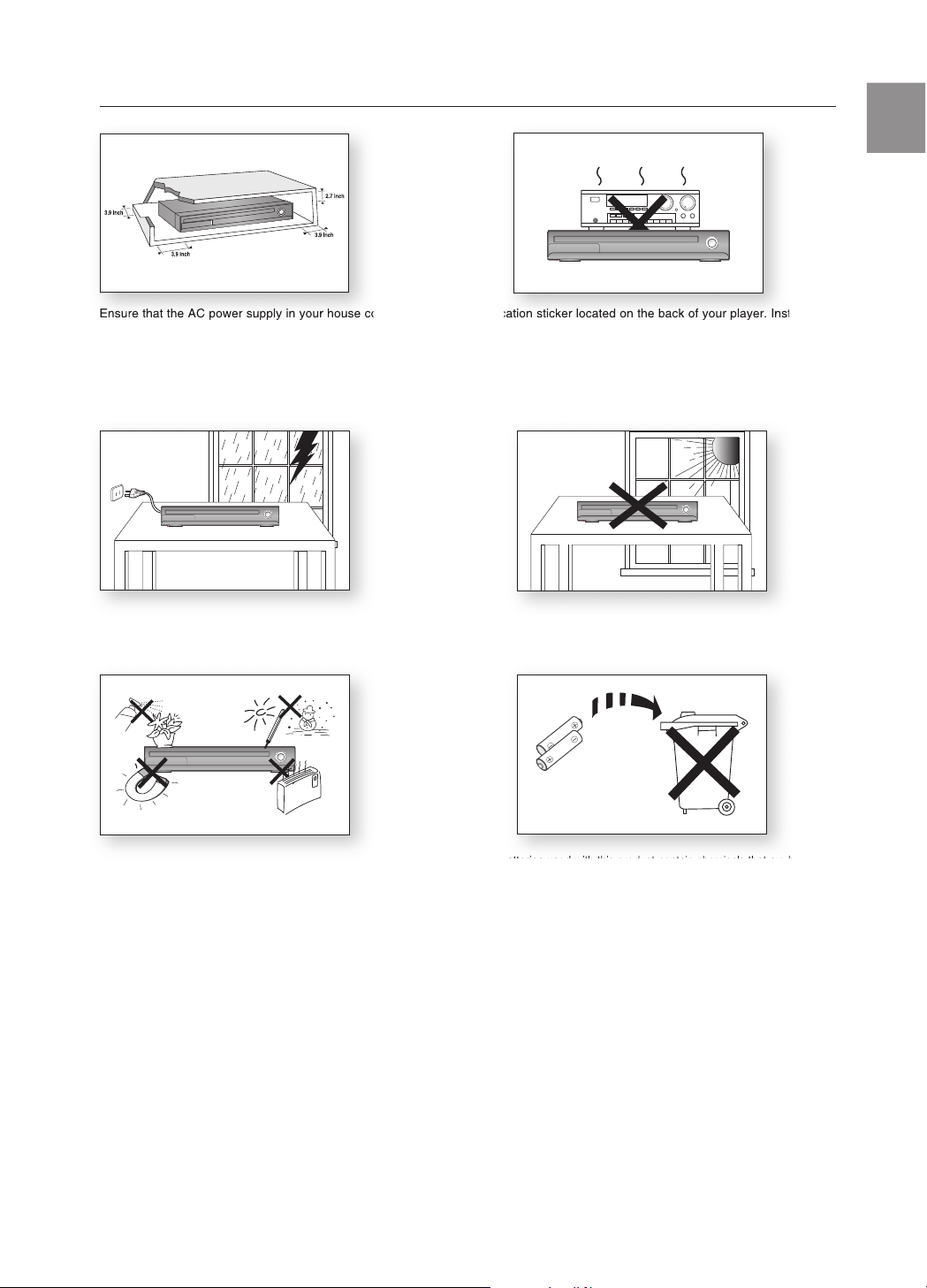
PRECAUTIONS
Ensure that the AC power supply in your house complies with the identification sticker located on the back of your player. Install your
player horizontally, on a suitable base (furniture), with enough space around it for ventilation (3~4 inches). Make sure the ventilation
slots are not covered. Do not stack anything on top of the player. Do not place the player on amplifiers or other equipment which
may become hot. Before moving the player, ensure the disc tray is empty. This player is designed for continuous use. Switching off
the DVD player to the stand-by mode does not disconnect the electrical supply. In order to disconnect the player completely from the
power supply, remove the main plug from the wall outlet, especially when left unused for a long period of time.
During thunderstorms, disconnect the AC main plug from the
wall outlet. Voltage peaks due to lightning could damage the unit.
Protect the player from moisture (i.e. vases) , and excess heat
(e.g.fireplace) or equipment creating strong magnetic or electric fields
(i.e.speakers...). Disconnect the power cable from the AC supply if the
player malfunctions. Your player is not intended for industrial use. Use of
this product is for personal use only.
Condensation may occur if your player or disc has been stored in
cold temperatures. If transporting the player during the winter,
wait approxi
mately 2 hours until the unit has reached room temperature
before using.
Do not expose the unit to direct sunlight or other heat sources.
This could lead to overheating and malfunction of the unit.
The batteries used with this product contain chemicals that are harmful
to the environment.
Do not dispose of batteries in the general household trash.
Phones

6
contents
FEATURES
2
3 What’s included
SAFETY INFORMATION
4
4 Safety Warnings
4 Important Safety Instructions
5 Precautions
GETTING STARTED
8
8 Before Reading the User’s Manual
9 Playable Discs
9 Do not use the following types of disc!
9 Copy Protection
10 Disc Type and Characteristics
DESCRIPTION
11
11 Front Panel
12 Display
13 Rear Panel
REMOTE CONTROL
14
14 Tour of the Remote Control
16 Setting the Remote Control
CONNECTIONS
18
18 Connecting the Speakers
23 Conecting the Rear Speakers to the
Wireless Receiving Amplifier
25 Connecting the Video Out to your TV
27 HDMI Function
28 Connecting an iPod
30 Connecting Audio from External
Components
32 Connecting the FM Antenna
33 Connecting the Optional XM Satellite Radio
Antenna and Receiver
PLAYBACK
35
35 Disc Playback
36 MP3/WMA-CD playback
37 JPEG File Playback
38 DivX Playback
40 Using The Playback Function
49 Using the iPod
50 Playing Media Files Using The USB Host
Feature
BEFORE USING YOUR HOME
THEATER
34
34 Before using your home theater

7
ENG
SYSTEM SETUP
52
52 Setting the Language
53 Setting TV Screen Type
54 Setting Parental Controls (Rating Level)
54 Setting the Password
55 Setting The Wallpaper
55 To Select one of the 3 Wallpaper Settings
you've made
56 DVD Playback Mode
56 Setting the Speaker Mode
57 Setting the Delay Time
58 Setting the Test Tone
59 Setting the Audio
59 Setting the DRC (Dynamic Range
Compression)
60 Setting the AV SYNC
60 Setting the HDMI Audio
61 Sound field (DSP)/EQ Function
61 Dolby Pro Logic II Mode
62 Dolby Pro Logic II Effect
62 P.BASS
63 ASC (Auto Sound Calibration) Setup
RADIO
65
65 Listening To Radio
65 Presetting Stations
66 XM satellite radio
CONVENIENT FUNCTION
69
69 Sleep Timer Function
69 Adjusting Display Brightness
69 Mute Function
TROUBLESHOOTING
70
70 Troubleshooting
USB HOST FEATURE SUPPORTED
PRODUCTS
72
72 Digital Camera
72 USB Flash Disc
72 MP3 Player
APPENDIX
73
73 Cautions on Handling and Storing Discs
74 Specifications
76 Warranty
getting started
8
getting started
BEFORE READING THE USER’S MANUAL
Make sure to check the following terms before reading the user manual.
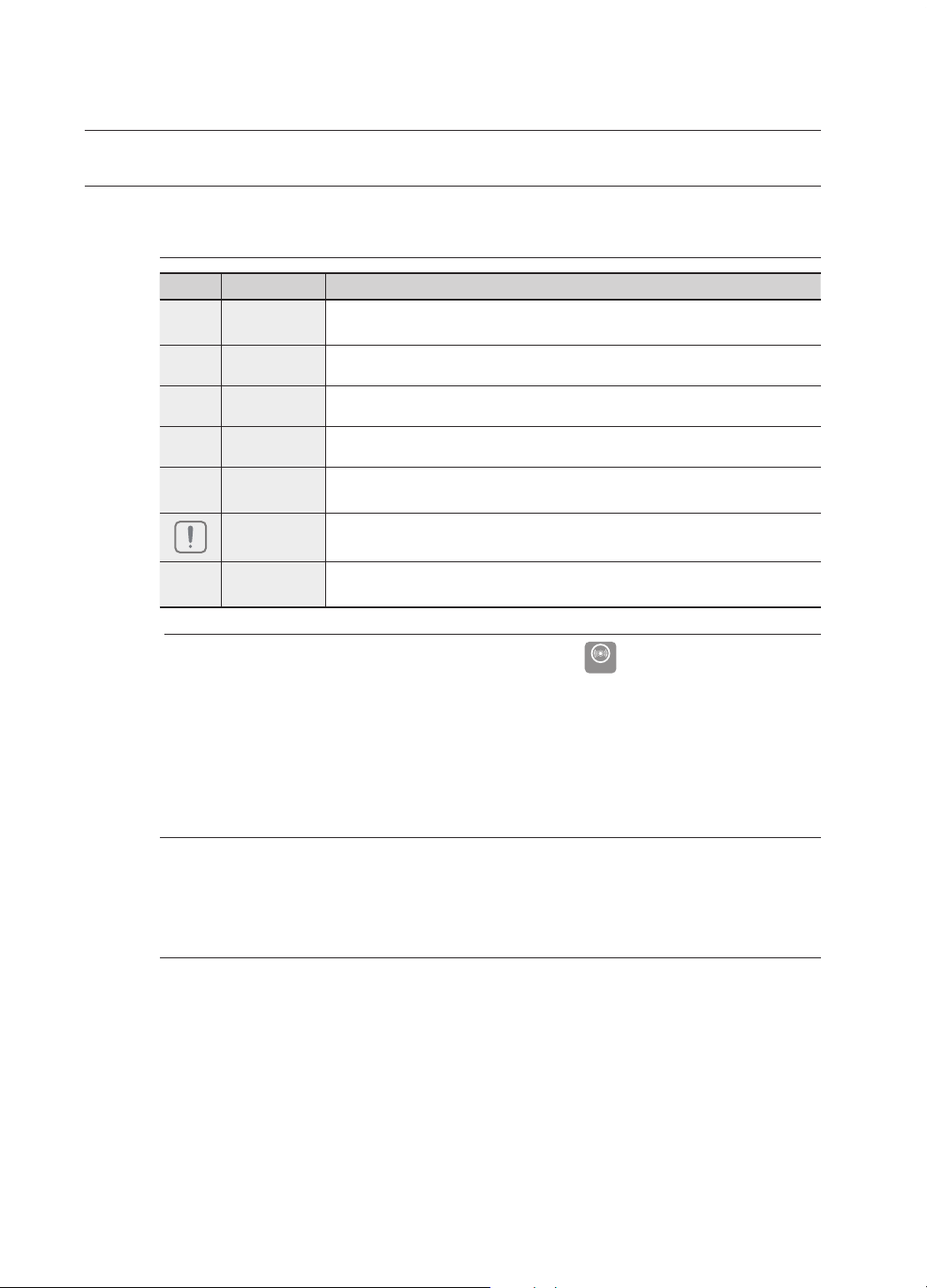
Icons that will be used in manual
Icon Term Definition
d
DVD
This involves a function available with DVD or DVD-R/DVD-RW discs that
have been recorded and finalized in Video Mode.
B
CD This involves a function available with a data CD (CD-R or CD-RW).
A
MP3 This involves a function available with CD-R/-RW discs.
G
JPEG This involves a function available with CD-R/-RW discs.
D
DivX
This involves a function available with MPEG4 discs.
(DVD±R/RW, CD-R or CD-RW)
Caution
This involves a case where a function does not operate or settings may be
cancelled.
M
Note
This involves tips or instructions on the page that help each function
operate.
In this manual, the instructions marked with "DVD (
DVD
)" are applicable to DVDVIDEO, DVD-AUDIO and DVD-R/-RW discs that have been recorded in Video Mode
and then finalized. Where a particular DVD type is mentioned, it is indicated
separately.
If a DVD-R/-RW disc has not been recorded properly in DVD Video format, it will not be
playable.
About the use of this user’s manual
Be sure to be familiar with Safety Instructions before using this product. (See pages 4~5)
If a problem occurs, check the Troubleshooting. (See pages 70~71)
Copyright
©2008 Samsung Electronics Co.,Ltd.
All rights reserved; No part or whole of this user’s manual may be reproduced or copied without the
prior written permission of Samsung Electronics Co.,Ltd.
M
`
`
1)
2)
9
ENG
● GETTING STARTED
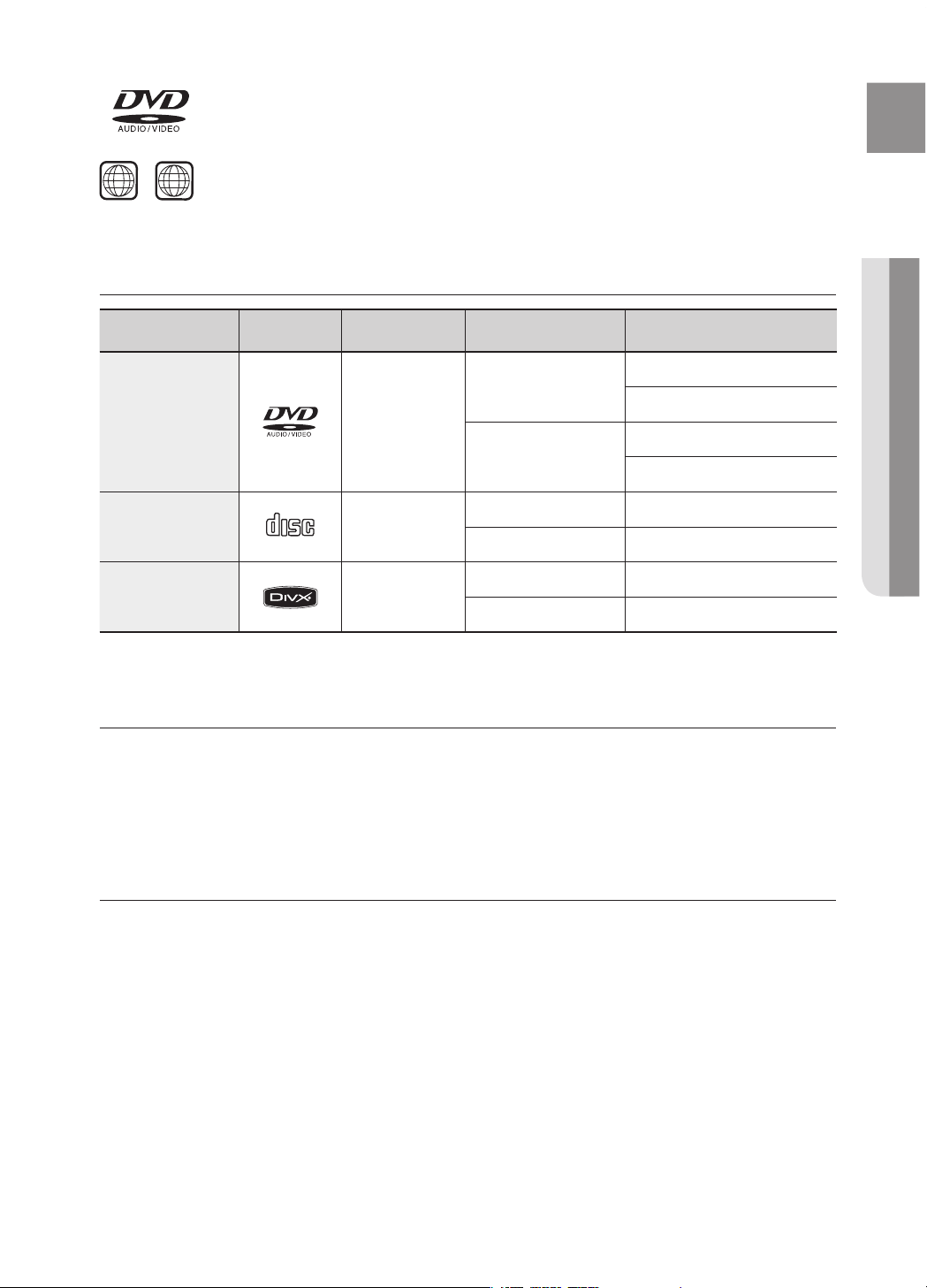
PLAYABLE DISCS
Disc Type Mark (Logo) Recorded Signals Disc Size Max. Playing Time
DVD-AUDIO
DVD-VIDEO
AUDIO + VIDEO
5 inches
Approx. 240 min. (single-sided)
Approx. 480 min. (double-sided)
3 1/2 inches
Approx. 80 min. (single-sided)
Approx. 160 min. (double-sided)
AUDIO-CD
COMPACT
DIGITAL AUDIO
AUDIO
5 inches 74 min.
3 1/2 inches 20 min.
DivX AUDIO + VIDEO
5 inches
—
3 1/2 inches
—
DO NOT USE THE FOLLOWING TYPES OF DISC!
LD, CD-G, CD-I, CD-ROM, DVD-ROM and DVD-RAM discs cannot be played on this player.
If such discs are played, a <WRONG DISC FORMAT> message appears on the TV screen.
DVD discs purchased abroad may not play on this player.
If such discs are played, a <CAN'T PLAY THIS DISC PLEASE, CHECK REGION CODE> message appears on the
TV screen.
COPY PROTECTION
Many DVD discs are encoded with copy protection. Because of this, you should only connect your DVD player
directly to your TV, not to a VCR. Connecting to a VCR results in a distorted picture from copy-protected DVD
discs.
This product incorporates copyright protection technology that is protected by methods claims of certain U.S.
patents and other intellectual property rights owned by Macrovision Corporation and other rights owners.
Use of this copyright protection technology must be authorized by Macrovision Corporation, and is intended
for home and other limited viewing uses only unless otherwise authorized by Macrovision Corporation.
Reverse engineering or disassembly is prohibited.
~
~
~
~
DVD (Digital Versatile Disc) offers fantastic audio and video, thanks to Dolby Digital
surround sound and MPEG-2 video compression technology. Now you can enjoy these
realistic effects in the home, as if you were in a movie theater or concert hall.
DVD players and the discs are coded by region. These regional codes must match in order for the
disc to play. If the codes do not match, the disc will not play.
The Region Number for this player is given on the rear panel of the player.
(Your DVD player will only play DVDs that are labeled with identical region codes.)
1 6
~

getting started
10
DISC TYPE AND CHARACTERISTICS
This product does not support Secure (DRM) Media files.
CD-R Discs
Some CD-R discs may not be playable depending on the disc recording device (CD-Recorder or PC) and the
condition of the disc.
Use a 650MB/74 minute CD-R disc.
Do not use CD-R discs over 700MB/80 minutes as they may not be played back.
Some CD-RW (Rewritable) media, may not be playable.
Only CD-Rs that are properly "closed" can be fully played. If the session is closed but the disc is left open, you
may not be able to fully play the disc.
CD-R MP3 Discs
Only CD-R discs with MP3 files in ISO 9660 or Joliet format can be played.
MP3 file names should be 8 characters or less in length and contain no blank spaces or special characters
(. / = +).
Use discs recorded with a compression/decompression data rate greater than 128Kbps.
Only files with the "mp3" and extensions can be played.
Only a consecutively written multisession disc can be played. If there is a blank segment in the Multisession
disc, the disc can be played only up to the blank segment.
If the disc is not closed, it will take longer to begin playback and not all of the recorded files may be played.
For files encoded in Variable Bit Rate (VBR) format, i.e. files encoded in both low bit rate and high bit rate
(e.g., 32Kbps ~ 320Kbps), the sound may skip during playback.
A maximum of 500 tracks can be played per CD.
A maximum of 300 folders can be played per CD.
CD-R JPEG Discs
Only files with the "jpg" extensions can be played.
If the disc is not closed, it will take longer to start playing and not all of the recorded files may be played.
Only CD-R discs with JPEG files in ISO 9660 or Joliet format can be played.
JPEG file names should be 8 characters or less in length and contain no blank spaces or special characters
(. / = +).
Only a consecutively written multisession disc can be played. If there is a blank segment in the multisession
disc, the disc can be played only up to the blank segment.
A maximum of 9,999 images can be stored on a single CD.
When playing a Kodak/Fuji Picture CD, only the JPEG files in the picture folder can be played.
Picture discs other than Kodak/Fuji Picture CDs may take longer to start playing or may not play at all.
DVD±R/RW, CD-R/RW DivX Discs
Since this product only provides encoding formats authorized by DivX Networks, Inc., a DivX file created by the
user might not play.
Software updates for incompatible formats are not supported.
(Example : QPEL, GMC, resolution higher than 800 x 600 pixels, etc.)
Sections with a high frame rate might not be played while playing a DivX file.
For more information about the formats authorized by DivX Networks, Inc., please visit "www.divxnetworks.
net".
❖
~
~
~
~
❖
~
~
~
~
~
~
~
~
~
❖
~
~
~
~
~
~
~
~
❖
~
~
~
~
11
ENG
● DESCRIPTION
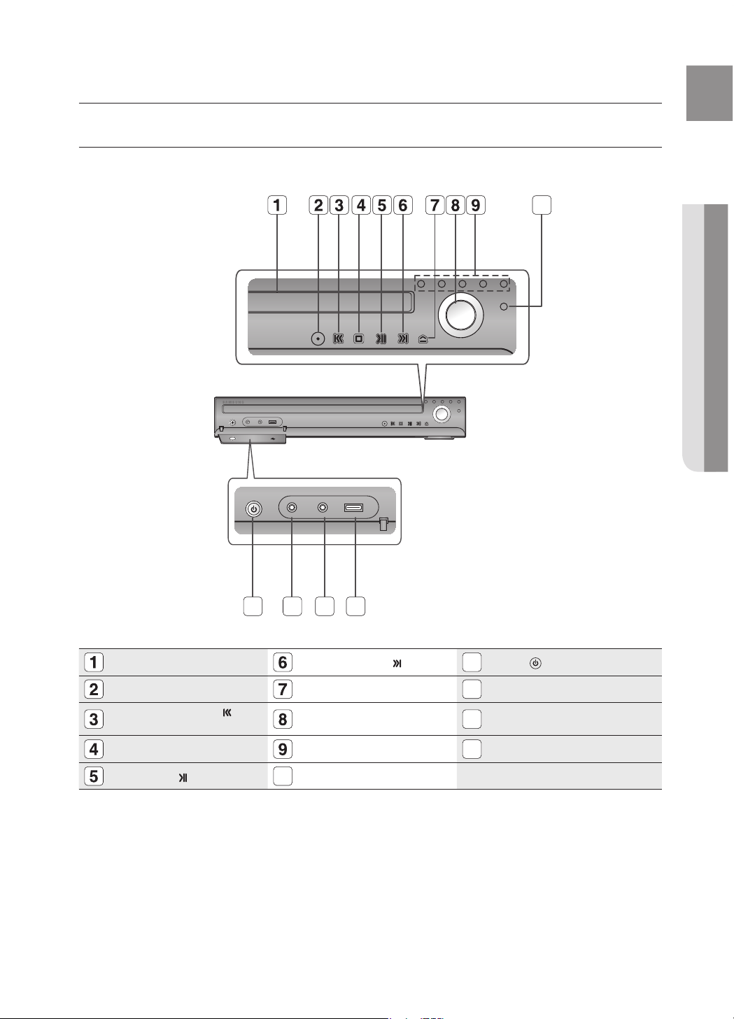
FRONT PANEL
DISC TRAY
TUNING UP & SKIP ( ) BUTTON
11
POWER( ) BUTTON
FUNCTION BUTTON
OPEN/CLOSE BUTTON
12
PHONES JACK
TUNING DOWN & SKIP ( )
BUTTON
VOLUME CONTROL
13
AUX IN 1/ASC (Auto Sound
Calibration) IN JACK
STOP (T) BUTTON
DIRECT PLAY 1~5 BUTTONS
14
USB PORT
PLAY/PAUSE ( ) BUTTON
10
DISC CHANGE BUTTON
FUNCTION
VOLUME
DISC
CHANGE
AUX IN 1
ASC IN
PHONES
FUNCTION
VOLUME
DISC
CHANGE
10
11
description
12 13 14

12
description
DISPLAY
FUNCTION DISPLAY USB INDICATOR
13
RADIO FREQUENCY INDICATOR
REPEAT INDICATOR
DTS DISC INDICATOR
14
DOLBY DIGITAL INDICATOR
HDMI INDICATOR
REPEAT INDICATOR
15
PRO LOGIC INDICATOR
DISC INDICATOR
10
DSP INDICATOR
16
LPCM INDICATOR
DVD INDICATOR
11
ASC (Auto Sound Calibration)
INDICATOR
CD INDICATOR
12
SYSTEM STATUS DISPLAY
10 11 13 14
15 16
12

13
ENG
● DESCRIPTION
REAR PANEL
XM Antenna Jack
Connect an XM Antenna to the XM Antenna Jack on the rear of this unit.
TX CARD CONNECTION (WIRELESS)
The TX card enables communication between the main unit and the
wireless receiver amplifi er.
iPod JACK
Connect the iPod dock connector here.
VIDEO OUTPUT JACK
Connect the TV's Video Input jack (VIDEO IN) to the VIDEO OUT jack.
AUX IN 2 JACKS
Connect to the 2CH analog output of an external device (such as a VCR)
COMPONENT VIDEO OUTPUT JACKS
Connect a TV with Component video inputs to these jacks.
External Digital Optical Input Jack
Use this to connect external equipment capable of digital output.
FM 75Ω COAXIAL JACK
Connect the FM antenna.
HDMI OUT JACK
Use the HDMI cable, connect this HDMI output terminal to the HDMI input
terminal on your TV for the best quality picture.
10
COOLING FAN
The fan always revolves when the power is on. Ensure a minimum of
4 inches of clear space on all sides of the fan when installing the product.
11
SPEAKER OUTPUT CONNECTORS
Connect the front, center speakers and subwoofer.
The rear speakers must be connected to the Wireless Receiver.
1 92 5 843 6 7
11
10
14
remote control
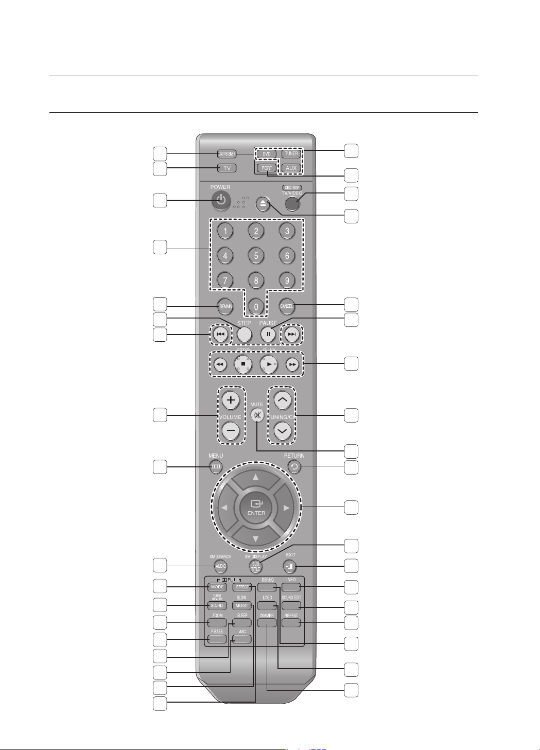
TOUR OF THE REMOTE CONTROL
2
1
35
34
33
32
31
30
29
28
27
26
25
24
23
22
21
20
19
17
16
15
14
13
12
11
10
9
8
7
6
5
4
3
36
18
37

15
ENG
● REMOTE CONTROL
20
PORT button
21
DISC SKIP, TV/VIDEO button
22
OPEN/CLOSE button
23
CANCEL button
24
PAUSE button
25
PLAY button
STOP button
SEARCH buttons
TUNING/CH button
MUTE button
RETURN button
Cursor/ENTER button
SUBTITLE/XM DISPLAY
EXIT
button
INFO
button
SOUND EDIT button
REPEAT button
DSP/EQ button
LOGO button
DIMMER button
DVD RECEIVER button
TV button
POWER button
Number (0~9) buttons
REMAIN button
STEP button
Tuning Preset/CD Skip buttons
VOLUME button
MENU button
AUDIO/XM SEARCH
PL II MODE button
TUNER MEMORY, SD(Standard
Definition)/HD(High Definition) button
ZOOM button
P.BASS button
SLEEP button
ASC button
SLOW, MO/ST button
PL II EFFECT button
DVD
DVD button
TUNER button
DVD
AUX button
36
35
34
33
32
31
30
29
28
27
26
19
17
16
15
14
13
12
11
10
9
8
7
6
5
4
3
2
1
Insert Remote Batteries
1. Remove the battery
cover in the direction
of the arrow.
2. Insert two 1.5V AAA batteries, paying
attention to the correct polarities
(+ and –).
3. Replace the battery
cover.
Follow these precautions to avoid leaking or cracking cells:
Place batteries in the remote control so they match the polarity : (+) to (+) and (–) to (–).
Use the correct type of batteries. Batteries that look similar may differ in voltage.
Always replace both batteries at the same time.
Do not expose the batteries to heat or a flame.
M
`
`
`
`
37
18
16
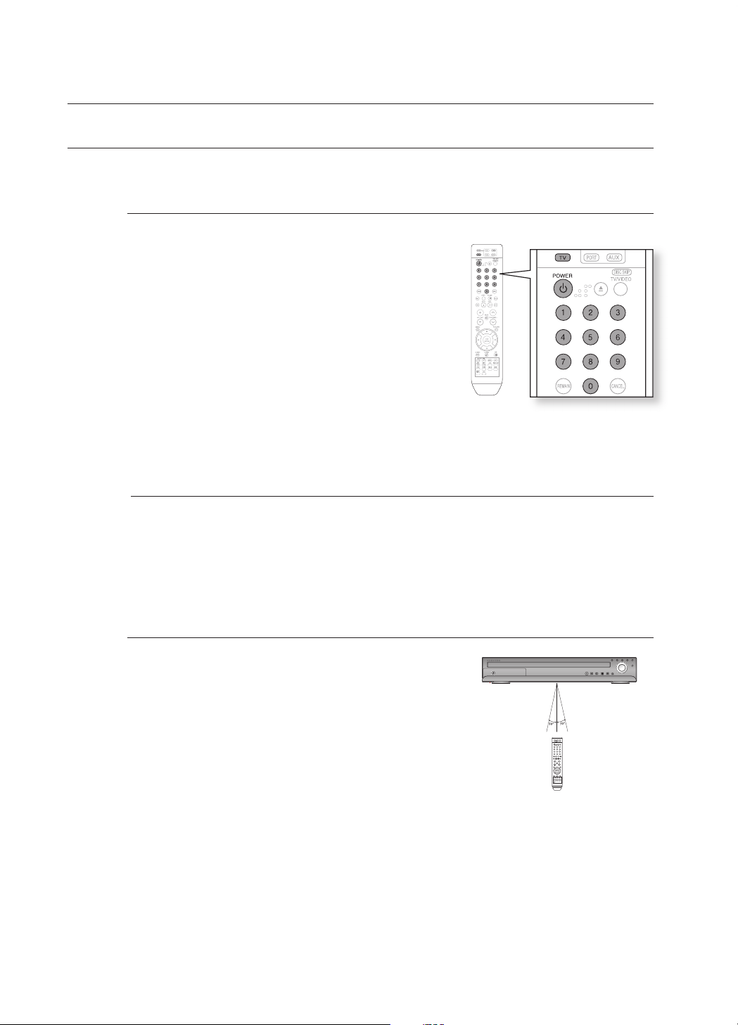
Operation Range of the Remote Control
The remote control can be used up to approximately
23 feet (7 meters) in a straight line.
It can also be operated at a horizontal angle of up to 30° from the
remote control sensor.
When operating a TV with the remote control
1. Press the TV button to set the remote to TV mode.
2. Press the POWER button to turn on the TV.
3. While holding down the POWER button, enter the code
corresponding to your brand of TV.
If there is more than one code listed for your TV in the
table, enter one at a time to determine which code works.
Example : For a Samsung TV
While holding down the POWER button, use the number
buttons to enter 00, 15, 16, 17 or 40.
4. If the TV turns off, the setting is complete.
You can use the TV POWER, VOLUME, CHANNEL, and
Numeric buttons (0~9).
The remote control may not work on some brands of TVs. Also, some operations may not
be possible depending on your brand of TV.
If you do not set the remote control with the code for your brand of TV, the remote control
will work on a Samsung TV by default.
~
~
M
`
`
FUNCTION
VOLUME
DISC
CHANGE
SETTING THE REMOTE CONTROL
You can control certain functions of your TV with this remote control.
remote control

17
ENG
● REMOTE CONTROL
TV Brand Code List
Admiral (M.Wards)
A Mark
Anam
AOC
Bell & Howell (M.Wards)
Brocsonic
Candle
Cetronic
Citizen
Cinema
Classic
Concerto
Contec
Coronado
Craig
Croslex
Crown
Curtis Mates
CXC
Daewoo
Daytron
Dynasty
Emerson
Fisher
Funai
Futuretech
General Electric (GE)
Hall Mark
Hitachi
Inkel
JC Penny
JVC
KTV
KEC
KMC
LG (Goldstar)
Luxman
LXI (Sears)
Magnavox
Marantz
Matsui
MGA
Mitsubishi/MGA
1
2
3
4
5
6
7
8
9
10
11
12
13
14
15
16
17
18
19
20
21
22
23
24
25
26
27
28
29
30
31
32
33
34
35
36
37
38
39
40
41
42
43
56, 57, 58
01, 15
01, 02, 03, 04, 05, 06, 07, 08, 09, 10, 11,
12, 13, 14
01, 18, 40, 48
57, 58, 81
59, 60
18
03
03, 18, 25
97
03
18
46
15
03, 05, 61, 82, 83, 84
62
03
59, 61, 63
03
02, 03, 04, 15, 16, 17, 18, 19, 20, 21, 22, 23, 24,
25, 26, 27, 28, 29, 30, 32, 34, 35, 36, 48, 59, 90
40
03
03, 15, 40, 46, 59, 61, 64, 82, 83, 84, 85
19, 65
03
03
06, 40, 56, 59, 66, 67, 68
40
15, 18, 50, 59, 69
45
56, 59, 67, 86
70
59, 61, 87, 88
03, 15, 40
15
01, 15, 16, 17, 37, 38, 39, 40, 41, 42, 43, 44
18
19, 54, 56, 59, 60, 62, 63, 65, 71
15, 17, 18, 48, 54, 59, 60, 62, 72, 89
40, 54
54
18, 40
18, 40, 59, 60, 75
44
45
46
47
48
49
50
51
52
53
54
55
56
57
58
59
60
61
62
63
64
65
66
67
68
69
70
71
72
73
74
75
76
77
78
79
80
81
82
83
84
85
86
MTC
NEC
Nikei
Onking
Onwa
Panasonic
Penney
Philco
Philips
Pioneer
Portland
Proton
Quasar
Radio Shack
RCA/Proscan
Realistic
Sampo
Samsung
Sanyo
Scott
Sears
Sharp
Signature 2000 (M.Wards)
Sony
Soundesign
Spectricon
SSS
Sylvania
Symphonic
Tatung
Techwood
Teknika
TMK
Toshiba
Vidtech
Videch
Wards
Yamaha
York
Yupiteru
Zenith
Zonda
Dongyang
18
18, 19, 20, 40, 59, 60
03
03
03
06, 07, 08, 09, 54, 66, 67, 73, 74
18
03, 15, 17, 18, 48, 54, 59, 62, 69, 90
15, 17, 18, 40, 48, 54, 62, 72
63, 66, 80, 91
15, 18, 59
40
06, 66, 67
17, 48, 56, 60, 61, 75
18, 59, 67, 76, 77, 78, 92, 93, 94
03, 19
40
00, 15, 16, 17, 40, 43, 46, 47, 48, 49,
59, 60, 98
19, 61, 65
03, 40, 60, 61
15, 18, 19
15, 57, 64
57, 58
50, 51, 52, 53, 55
03, 40
01
18
18, 40, 48, 54, 59, 60, 62
61, 95, 96
06
18
03, 15, 18, 25
18, 40
19, 57, 63, 71
18
59, 60, 69
15, 17, 18, 40, 48, 54, 60, 64
18
40
03
58, 79
01
03, 54
No.
Brand
Code
No
.
Brand
Code
18
CONNECTING THE SPEAKERS
Position of the DVD Player
Place it on a stand or cabinet shelf, or under the TV stand.
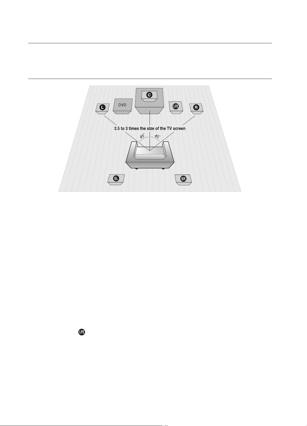
Selecting the Listening Position
The listening position should be located about 2.5 to 3 times the distance of the TV's screen size away from the TV.
Example : For 32" TVs 2~2.4m (6~8feet)
For 55" TVs 3.5~4m (11~13feet)
Front Speakers
ei
Place these speakers in front of your listening position, facing inwards (about 45°) toward you.
Place the speakers so that their tweeters will be at the same height as your ear.
Align the front face of the front speakers with the front face of the center speaker or place them slightly in front
of the center speakers.
Center Speaker
f
It is best to install it at the same height as the front speakers. You can also install it directly over or under the TV.
Rear Speakers
hj
Place these speakers behind your listening position. If there isn't enough room, place these speakers so they face each
other. Place them about 60 to 90cm (2 to 3feet) above your ear, facing slightly downward.
*
Unlike the front and center speakers, the rear speakers are used to handle mainly sound effects and sound will not
come from them all the time.
*
Sound will be heard from the rear speakers in DVD 5.1-CH or Dolby Pro Logic II mode only.
Subwoofer
The position of the subwoofer is not so critical. Place it anywhere you like.
This section involves various methods of connecting the Digital Home Theater to other external components.
Before moving or installing the product, be sure to turn off the power and disconnect the power cord.
connections
19
ENG
● CONNECTIONS
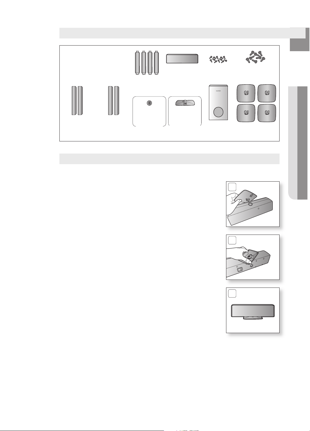
Speaker Components
SubWooFer
(aH81-03846D)
StanD baSe
(aH81-03846p)
Front
L (aH81-03846e)
r (aH81-03846S)
SCREW (Large): 8EA
(aH81-03943a)
SCREW (Small): 12EA
(aH81-03944a)
CRADLE STAND/
WALL MOUNT
CENTER
(aH81-03469a)
CENTER
(aH81-03853a)
HoLe CoVer
(L) (r)
StanD
(aH81-03846n)
Center
(aH81-03846F)
rear
L (aH81-03846G)
r (aH81-03846t)
(L) (r)
Installing the Cradle Stand (Center speaker)
1. Insert the stand so that it fi ts into the hole as described in the fi gure.
2. Turn the stand clockwise to lock it.
(Turning it counter-clockwise will loosen from the hole.)
3. This is the completion of the stand installation.
1
2
3

20
connections
4
5
4. Use a coin turn the hole cover clock wise to fi x it.
(Turning it count-clock wise will loosen from the hole.)
5. Use the wall mount hole (bracket) to install the speaker on the wall.
To avoid accident fall and consequent damage to the customer and speaker, make sure
the speaker is hung safely.
M `
Installing the Wall Mount (Center speaker)
1. Insert the wall mount so that it fi ts into the rear hole of the speaker
as in the fi gure.
2. Turn the wall mount counter clockwise to fi x it. (This is the reverse
direction to the cradle stand.)
3. Put the hole cover on the hole of the speaker.
1
2
3
CONNECTING THE SPEAKERS (CON'T)
21
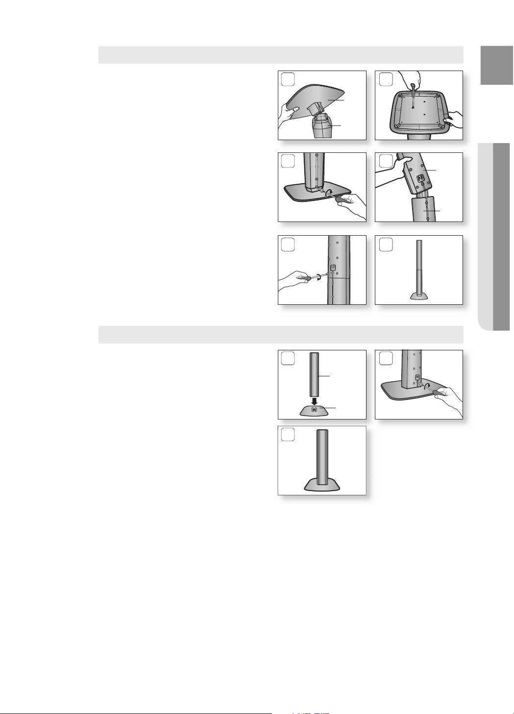
ENG
● CONNECTIONS
Turn the STAND upside-down and connect
it to the STAND BASE.
Insert three small SCREWS into three holes
marked with arrows using a screwdriver as
shown in the illustration.
Insert a large SCREW into the hole on the
rear of the Speaker STAND.
Connect the assembled stand to the
SPEAKER.
Insert another large SCREW into the hole
on the rear of the speaker using a
screwdriver as shown in the illustration.
This is the successfully assembled speaker.
Make sure that the speaker is installed on a
fl at and stable area. Otherwise it may be
easily knocked over.
1.
2.
3.
4.
5.
6.
1 2
5 6
How to Install the Speaker on the Stand
STAND
BASE
3 4
STAND
SPEAKER
STAND
How to Install the Speaker on the Stand Base
Connect the SPEAKER with the
STAND BASE.
Insert the SCREW into the hole on the rear
of the speaker using a screwdriver as shown
in the illustration.
This is the SPEAKER successfully
assembled with the Stand Base.
1.
2.
3.
1 2
3
SPEAKER
STAND
BASE
22
connections
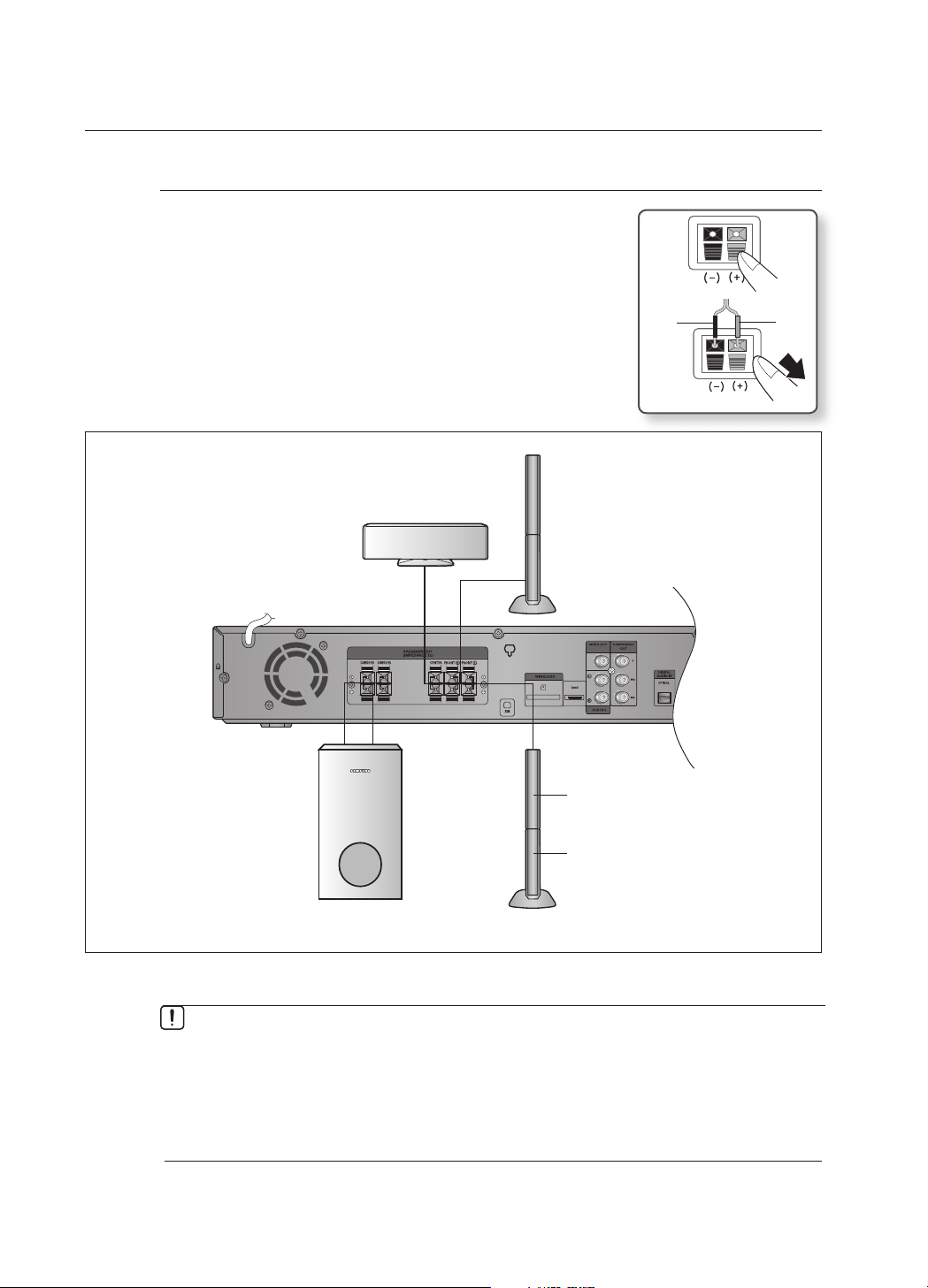
Connecting the Front, Center and Subwoofer Speakers
Press down the terminal tab on the back of the speaker.
Insert the black wire into the black terminal (–) and the red wire into
the red (+) terminal, and then release the tab.
Connect the connecting plugs to the back of the Home Theater.
Make sure the colors of the speaker terminals match the colors of
the connecting plugs.
1.
2.
3.
~
Black
Red
If you place a speaker near your TV set, screen color may be distorted because of the
magnetic fi eld generated by the speaker. If this occurs, place the speaker away from your
TV set.
M `
Do not let children play with or near the speakers. They could get hurt if a speaker falls.
When connecting the speaker wires to the speakers, make sure that the polarity (+/ –) is correct.
Keep the subwoofer speaker out of reach of children so as to prevent children from
inserting their hands or alien substances into the duct (hole) of the subwoofer speaker.
Do not hang the subwoofer on a wall through the duct (hole).
`
`
`
`
Subwoofer
Center Speaker
Front
Speaker (R)
Front Speaker (L)
Speaker
Stand
* To connect the rear speakers, refer to page 23.
23
ENG
● CONNECTIONS
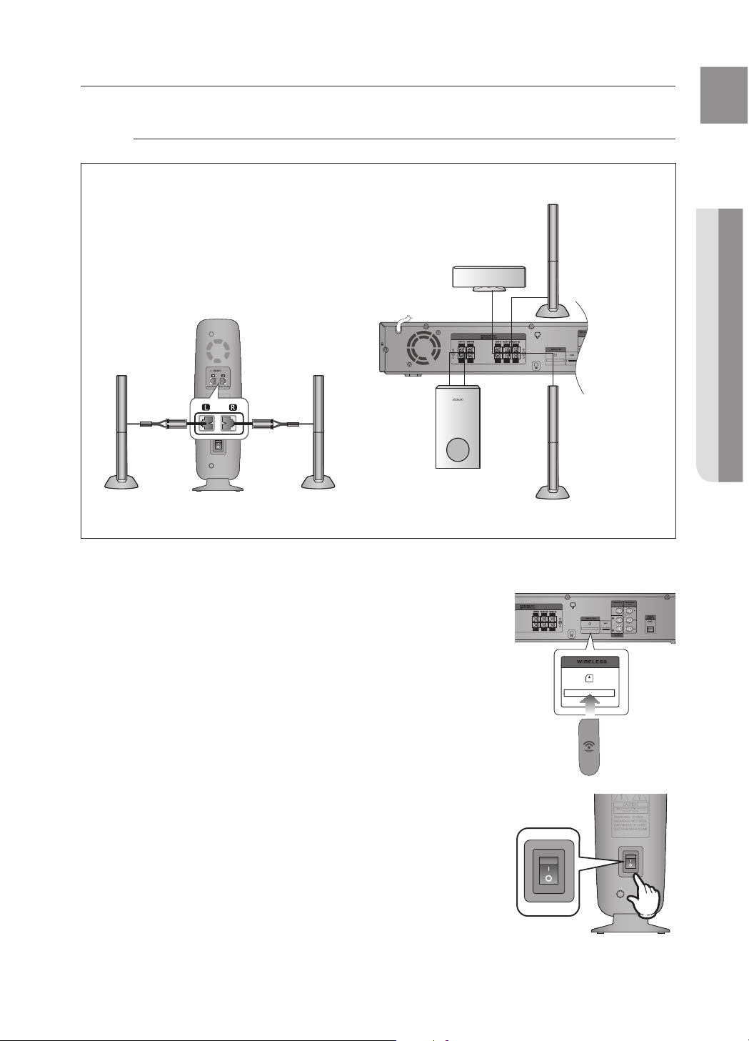
CONNECTING THE REAR SPEAKERS TO THE WIRELESS RECEIVING AMPLIFIER
Wireless Receiving Module (SWA-4000)
Front Speaker (R)
Rear Speaker (L)
Subwoofer
Center Speaker
Rear Speaker (R)
WIRELESS RECEIVER MODULE
Front Speaker (L)
Connect the front, center and Subwoofer speakers to the
DVD Player, referring to page 21.
With the DVD Player turned off, insert the TX card into the
TX Card Connection(WIRELESS) on the back of the main unit.
Hold the TX card so that the slanted side faces to the left
and insert the card into the port.
The TX card enables communication between the main
unit and the wireless receiver.
Connect the left and right rear speakers to the wireless
receiving module.
Plug the power cord of the wireless receiving module
in the wall outlet and switch the power switch ON.
1.
2.
~
~
3.
4.
Slanted side face left
TX card
RESET
 Loading...