

Samsung HT-Q80, HT-TQ85 User Manual
Home Theater System
with 5 Disc DVD Changer
and HDMI
HT-Q80
HT-TQ85
Instruction Manual
COMPACT
DIGITAL AUDIO
SAMSUNG ELECTRONICS AMERICA, INC.
SERVICE DIVISION
400 Valley Road, Suite 201
Mount Arlington, NJ 07856
1-800-SAMSUNG (1-800-726-7864)
www.samsung.com
AH68-01834A

ENG
12
Safety Warnings Precautions
Ensure that the AC power supply in your house complies with the identification sticker located on the back of your player. Install your
player horizontally, on a suitable base (furniture), with enough space around it for ventilation (3~4inches). Make sure the ventilation
slots are not covered. Do not stack anything on top of the player. Do not place the player on modules or other equipment which may
become hot. Before moving the player, ensure the disc tray is empty. This player is designed for continuous use. Switching off the
Home Theater to the stand-by mode does not disconnect the electrical supply. In order to disconnect the player completely from the
power supply, remove the main plug from the wall outlet, especially when left unused for a long period of time.
Protect the player from moisture(i.e. vases) , and excess heat
(e.g.fireplace) or equipment creating strong magnetic or electric fields
(i.e.speakers...). Disconnect the power cable from the AC supply if the
player malfunctions. Your player is not intended for industrial use.
Use of this product is for personal use only.
Condensation may occur if your player or disc has been stored in cold
temperatures.
If transporting the player during the winter, wait approximately 2 hours
until the unit has reached room temperature before using.
Phones
During thunderstorms, disconnect AC main plug from the
wall outlet.
Voltage peaks due to lightning could damage the unit.
Do not expose the unit to direct sunlight or other heat
sources.
This could lead to overheating and malfunction of the unit.
The batteries used with this product contain chemicals
that are harmful to the environment.
Do not dispose of batteries in the general household
trash.
PREPARATION
CLASS 1 LASER PRODUCT
This Compact Disc player is classified as a CLASS 1
LASER product.
Use of controls, adjustments or performance of
procedures other than those specified herein may result
in hazardous radiation exposure.
CAUTION-INVISIBLE LASER RADIATION WHEN OPEN
AND INTERLOCKS DEFEATED, AVOID
EXPOSURE TO BEAM.
This symbol indicates that dangerous voltage which can cause electric shock is present inside
this unit.
This symbol alerts you to important operating and maintenance instructions accompanying
the unit.
WARNING: To reduce the risk of fire or electric shock, do not expose this appliance to rain or moisture.
CAUTION: TO PREVENT ELECTRIC SHOCK, MATCH WIDE BLADE OF PLUG TO WIDE SLOT, FULLY
INSERT.
CLASS 1 LASER PRODUCT
KLASSE 1 LASER PRODUKT
LUOKAN 1 LASER LAITE
KLASS 1 LASER APPARAT
PRODUCTO LASER CLASE 1
RISK OF ELECTRIC SHOCK.
DO NOT OPEN
CAUTION:
TO REDUCE THE RISK OF ELECTRIC
SHOCK, DO NOT REMOVE REAR COVER.
NO USER SERVICEABLE PARTS INSIDE.
REFER SERVICING TO QUALIFIED
SERVICE PERSONNEL.
CAUTION
Note to CATV system installer :
This reminder is provided to call the CATV system
installer’s attention to Section 820~40 of the NEC
which provides guidelines for proper grounding and,
in particular, specifies that the cable ground shall be
connected to the grounding system of the building,
as close to the point of cable entry as practical

ENG
43
READ INSTRUCTIONS
All the safety and operating instructions should be
read before the appliance is operated.
RETAIN INSTRUCTIONS
The safety and operating instructions should be
retained for future reference.
HEED WARNINGS
All warnings on the appliance and in the operating
instructions should be adhered to.
FOLLOW INSTRUCTIONS
All operating and use instructions should be
followed.
WATER AND MOISTURE
Do not use this video product near waterfor example, near a bathtub, wash bowl,
kitchen sink, or laundry tub, in a wet basement,
or near a swimming pool, and the like.
OVERLOADING
Do not overload wall outlets and extension cords as
this can result in the risk of fire
or electric shock.
VENTILATION
Slots and openings in the cabinet are provided
for ventilation and to ensure reliable operation of the
video product and to protect it from overheating
these openings must not be blocked or covered.
The openings should never be blocked
by placing the video product on a bed, sofa, rug, or
other similar surface. This video product
should never be placed near or over a radiator or
heat register.
This video product should not be placed
in a built-in installation such as a bookcase
or rack unless proper ventilation is provided
or the manufacturer's instructions have been followed.
POWER CORD PROTECTION
Power-supply cords should be routed so that
they are not likely to be walked on or pinched
by items placed upon or against them paying
particular attention to cords at plugs,
convenience receptacles, and the point where
they exit from the appliance.
CLEANING
Unplug this video product from the wall outlet
before cleaning. Do not use liquid cleaners
or aerosol cleaners. Use a damp cloth for cleaning.
LIGHTNING
For added protection of this video product
receiver during a lightning storm, or when
it is left unattended and unused for long
periods of time, unplug it from the wall outlet
and disconnect the antenna or cable system.
This will prevent damage to the video product
due to lightning and power-line surges.
OBJECT AND LIQUID ENTRY
Never push objects of any kind into this
product through openings as they may touch
dangerous voltage points or short-out parts
that could result in a fire or electric shock.
Never spill liquid of any kind on the video
product.
ACCESSORIES
Do not place this video product on an unstable cart,
stand, tripod, bracket, or table.
The video product may fall, causing serious injury to
a child or adult, and serious damage
to the appliance.
Use only with a cart, stand, tripod, bracket,
or table recommended by the manufacturer,
or sold with the video product. Any mounting
of the appliance should follow the manufacturer's
instructions and should use a mounting accessory
recommended by the manufacturer.
CART
An appliance and cart combination should be moved
with care. Quick stops, excessive force, and uneven
surfaces may cause the appliance and cart combination to overturn.
POWER SOURCES
This video product should be operated only from the
type of power source indicated
on the marking label. If you are not sure
of the type of supply to your home, consult your
appliance dealer or local power company.
For video products intended to be operated from battery power, or other sources, refer
to the operating instructions.
POWER LINES
An outside antenna system should not be located in
the vicinity of overhead power lines or other electric
light or power circuits,
or where it can fall into such power lines
or circuits. When installing an outside antenna system, extreme care should be taken to keep from
touching such power lines or circuits as contact with
them might be fatal.
POLARIZATION
This video product is equipped with a polarized
alternating current line plug (a plug having one
blade wider than the other.) This plug will fit into the
power outlet only one way.
This is a safety feature. If you are unable
to insert the plug fully into the outlet, try reversing
the
plug. If the plug should still fail to fit, contact your
electrician to replace your obsolete outlet. Do not
defeat the safety purpose of the polarized plug.
OUTDOOR ANTENNA GROUNDING
•
If an outside antenna is connected to the
antenna terminal, be sure the antenna system
is grounded so as to provide some protection
against voltage surges and built-up static
charges.
•
In the U.S.A section 810 of the National
Electrical Code, ANSI/NFPA No. 70-1984,
provides information with respect to proper
grounding of the mast and supporting
structure, grounding of the lead-in wire
to an antenna discharge unit, size of grounding
conductors, location of antenna discharge unit,
connection to grounding electrodes, and
requirements for the grounding electrode.
See the figure below.
ATTACHMENTS
Do not use attachments not recommended
by the video product manufacturer as they may
cause hazards.
SERVICING
•
Do not attempt to service this product yourself
as opening or removing covers may expose
you to dangerous voltage or other hazards.
•
Refer all servicing to qualified service personnel.
REPLACEMENT PARTS
When replacement parts are required, be sure the
service technician has used replacement parts specified by the manufacturer or having the same characteristics as the original part. Unauthorized substitutions may result in fire, electric shock or other hazards.
SAFETY CHECK
Upon completion of any service or repairs
to this video product, ask the service technician to
perform safety checks to determine that the video
product is in proper operating condition.
DAMAGE REQUIRING SERVICE
Unplug this video product from the wall outlet
and
refer servicing to qualified service personnel
under
the following conditions.
a.
When the power-supply cord or plug is damaged.
b. If liquid has been spilled, or objects have
fallen into the video product.
c. If the video product has been exposed to rain
or water
d.
If the video product does not operate normally
by following the operating instructions.
Adjust only those controls that are covered
by the operating instructions as an improper
adjustment of other controls may result
in damage and will often require extensive
work by a qualified technician to restore
the video product to its normal operation.
e. If the video product has been dropped
or the cabinet has been damaged.
f. When the video product exhibits a distinct
change in performance - this indicates
a need for service.
HEAT
This video unit should be situated away from heat
sources such as radiators, stoves, or other products
(including modules) that produce heat.
ANTENNA
LEAD IN WIRE
ANTENNA
DISCHARGE UNIT
(NEC SECTION. 810-20)
GROUNDING CONDUCTORS
(NEC SECTION 810-21)
GROUND CLAMPS
POWER SERVICE GROUNDING
ELECTRODE SYSTEM
(NEC ART 250, PART H)
GROUND
CLAMP
ELECTRIC
SERVICE
EQUIPMENT
PREPARATION
Safety Instructions
PREPARATION
Safety Warnings .................................................................1
Precautions.........................................................................2
Safety Instructions..............................................................3
Features .............................................................................5
Notes on Discs ...................................................................7
Description..........................................................................9
CONNECTIONS
Connecting the Speakers ...................................................13
Connecting the optional Wireless Receiving Amplifier.......15
Connecting the Video Out to TV ........................................18
Connecting the HDMI IN/OUT............................................19
HDMI Function....................................................................20
Connecting External Components......................................22
Connecting the FM Antenna...............................................23
Connecting an optional XM Satellite Radio Antenna .........24
OPERATION
Before Using Your Home Theater ......................................25
Disc Playback.....................................................................27
Selecting a Disc in the Disc changer .................................28
MP3/WMA-CD Playback ....................................................29
Displaying Disc Information................................................30
JPEG File Playback............................................................31
DivX Playback ....................................................................33
Checking the Remaining Time ...........................................35
Fast/Slow Playback ............................................................36
Skipping Scenes/Songs......................................................36
Repeat Playback ................................................................37
A-B Repeat Playback .........................................................38
Step Function .....................................................................39
Angle Function....................................................................39
Zoom (Screen Enlarge) Function .......................................40
EZ VIEW Function..............................................................40
Bonus Group / Navigating Pages.......................................41
Selecting Audio/Subtitle Language.....................................42
Playing Media Files using the USB HOST feature.............43
Moving Directly to a Scene/Song .......................................45
Using Disc Menu ................................................................46
Using the Title Menu...........................................................46
SETUP
Setting the Language .........................................................47
Setting TV Screen type ......................................................49
Setting Parental Controls (Rating Level)............................51
Setting the Password .........................................................52
Setting the Wallpaper .........................................................53
DVD Playback Mode ..........................................................55
Setting the Speaker Mode..................................................56
Setting the Delay Time.......................................................57
Setting the Test Tone..........................................................59
Setting the DRC (Dynamic Range Compression)..............60
Setting the Audio ...............................................................61
AV SYNC Setup .................................................................63
Sound Field (DSP)/EQ Function ........................................64
Dolby Pro Logic II Mode.....................................................65
Dolby Pro Logic II Effect.....................................................66
RADIO OPERATION
Listening to Radio...............................................................67
Presetting Stations .............................................................68
Before Using XM Satellite Radio........................................69
Listening to XM Satellite Radio .........................................70
XM Display Mode ..............................................................71
XM Search Mode ...............................................................73
Presetting XM Satellite Radio.............................................74
MISCELLANEOUS
Convenient Functions.........................................................75
Operating a TV with the Remote Control ...........................77
Before Calling for Service...................................................79
Cautions on Handling and Storing Discs............................81
Language Code List ...........................................................82
USB Host Feature Supported Products .............................83
Specifications .....................................................................84
Speaker Installation
How to install the speaker and the stand...........................85
65
Multi-Disc Playback & FM Tuner
The HT-Q80/HT-TQ85 combines the convenience of multi-disc playback capability, including
DVD-AUDIO, DVD-VIDEO, CD, MP3-CD, WMA-CD, DivX, CD-R/RW, and DVD-R/RW, with a
sophisticated FM tuner, all in a single player.
Dolby Pro Logic II
Dolby Pro Logic II is a new form of multi-channel audio signal decoding technology
that improves upon existing Dolby Pro Logic.
DTS (Digital Theater Systems)
DTS is an audio compression format developed by Digital Theater Systems Inc.
It delivers full-frequency 5.1 channel sound.
Power Saving Function
The HT-Q80/HT-TQ85 automatically shuts itself off after 20 minutes in stop mode.
TV Screen Saver Function
The HT-Q80/HT-TQ85 automatically brightens and darkens your TV screen
after 3 minutes in the stop mode.
The HT-Q80/HT-TQ85 automatically switches itself into the power saving mode
after 20 minutes in the screen saver mode.
Customized TV Screen Display
The HT-Q80/HT-TQ85 allows you to select your favorite image during JPEG and DVD
playback and set it as your background wallpaper.
PREPARATION
Features
Contents
ENG
HDMI
HDMI transmits DVD video and audio signals simultaneously, and provides a clearer picture.
USB Host Play
You can enjoy media files such as pictures, movies and tunes saved in an MP3 player, digital
camera or USB memory by connecting the storage device to the USB port of the home theater.
AV SYNC Function
Video may lag behind the audio if the unit is connected to a digital TV.
To compensate for this, you can adjust the audio delay time to sync up with the video.
Optional XM radio
Samsung ’s XM Ready Home Theater Systems give you the opportunity to enjoy America ’s
leading satellite radio service in CD-quality sound.
Optional Wireless receiver amplifier
Samsung ’s optional rear-channel wireless module does away with cables running between
your DVD receiver and rear-channel speakers. Instead,the rear speakers connect to a compact wireless module that communicates with your DVD receiver.
ENG
87
PREPARATION
CD-R Discs
•
Some CD-R discs may not be playable depending on the disc recording device (CD-Recorder or PC) and the
condition of the disc.
•
Use a 650MB/74 minute CD-R disc.
Do not use CD-R discs over 700MB/80 minute as they may not be played back.
•
Some CD-RW (Rewritable) media, may not be playable.
•
Only CD-Rs that are properly "closed" can be fully played. If the session is closed but the disc is left open, you
may not be able to fully play the disc.
CD-R JPEG Discs
•
Only files with the ".jpeg" and ".JPEG" extensions can be played.
•
If the disc is not closed, it will take longer to start playing and not all of the recorded files may be played.
•
Only CD-R discs with JPEG files in ISO 9660 or Joliet format can be played.
•
JPEG file names should be 8 characters or less in length and contain no blank spaces or special characters (. / = +).
•
Only a consecutively written multisession disc can be played. If there is a blank segment in the multisession disc, the
disc can be played only up to the blank segment.
•
A maximum of 9,999 images can be stored on a single CD.
•
When playing a Kodak/Fuji Picture CD, only the JPEG files in the picture folder can be played.
•
Picture discs other than Kodak/Fuji Picture CDs may take longer to start playing or may not play at all.
Disc Recording Format
CD-R MP3 Discs
•
Only CD-R discs with MP3 files in ISO 9660 or Joliet format can be played.
•
MP3 file names should be 8 characters or less in length and contain no blank spaces or special characters (. / = +).
•
Use discs recorded with a compression/decompression data rate greater than 128Kbps.
•
Only files with the ".mp3" and ".MP3" extensions can be played.
•
Only a consecutively written Multisession disc can be played. If there is a blank segment in the Multisession disc,
the disc can be played only up to the blank segment.
•
If the disc is not closed, it will take longer to begin playback and not all of the recorded files may be played.
•
For files encoded in Variable Bit Rate (VBR) format, i.e. files encoded in both low bit rate and high bit rate
(e.g., 32Kbps ~ 320Kbps), the sound may skip during playback.
•
Amaximum of 500 tracks can be played per CD.
•
A maximum of 300 folders can be played per CD.
DVD (Digital Versatile Disc) offers fantastic audio and video, thanks to Dolby Digital sur-
round sound and MPEG-2 video compression technology. Now you can enjoy these realistic
effects in the home, as if you were in a movie theater or concert hall.
V I D E O
DVD players and the discs are coded by region. These regional codes must match in order
for the disc to play. If the codes do not match, the disc will not play.
The Region Number for this player is given on the rear panel of the player.
(Your DVD player will only play DVDs that are labeled with identical region codes.)
1 6
~
•
LD, CD-G, CD-I, CD-ROM and DVD-ROM discs cannot be played on this player.
If such discs are played, a "WRONG DISC FORMAT" message appears on the TV screen.
•
DVD discs purchased abroad may not play on this player.
If such discs are played, a "WRONG REGION CODE" message appears on the TV screen.
Do not use the following types of disc!
•
Many DVD discs are encoded with copy protection. Because of this, you should only connect
your DVD player directly to your TV, not to a VCR. Connecting to a VCR results in a distorted picture from copy-protected DVD discs.
•
This product incorporates copyright protection technology that is protected by methods claims of certain
U.S. patents and other intellectual property rights owned by Macrovision Corporation and other rights
owners. Use of this copyright protection technology must be authorized by Macrovision Corporation, and
is intended for home and other limited viewing uses only unless otherwise authorized by Macrovision
Corporation. Reverse engineering or disassembly is prohibited.
Copy Protection
Notes on Discs
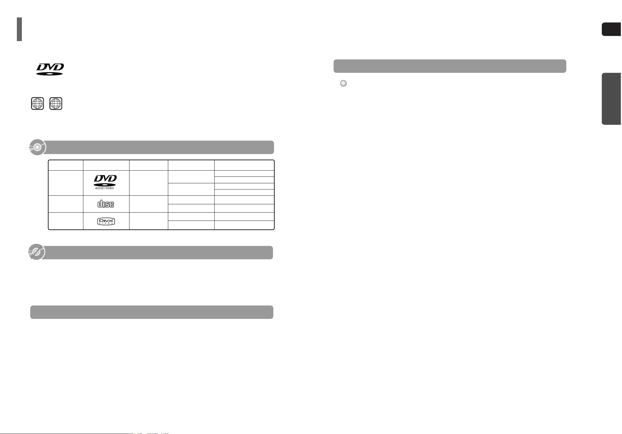
COMPACT
DIGITAL AUDIO
Mark (Logo)
Audio + Video
DVD
AUDIO-CD
5"
Approx. 240 min. (single-sided)
Approx. 480 min. (double-sided)
Approx. 80 min. (single-sided)
Approx. 160 min. (double-sided)
74 min.
20 min.
74 min.
20 min.
3 1/2"
5"
3 1/2"
Audio
Recorded Signals
Disc Type Disc Size Max. Playing Time
Playable Discs
DivX
5"
3 1/2"
MPEG4
MP3
CD-R/RW DivX Discs
•
Since this product only provides encoding formats authorized by DivX Networks, Inc., a DivX file created by the user
might not be played.
•
Software update for unsupported formats is not supported.
(Example: QPEL, GMC, resolution higher than 720 x 480 pixels, etc.)
•
Sections with high frame rate might not be played while playing a DivX file.
•
For more information about the formats authorized by DivX Networks, Inc., visit "www.divxnetworks.net".
This product does not support Secure (DRM) Media files.
ENG
9
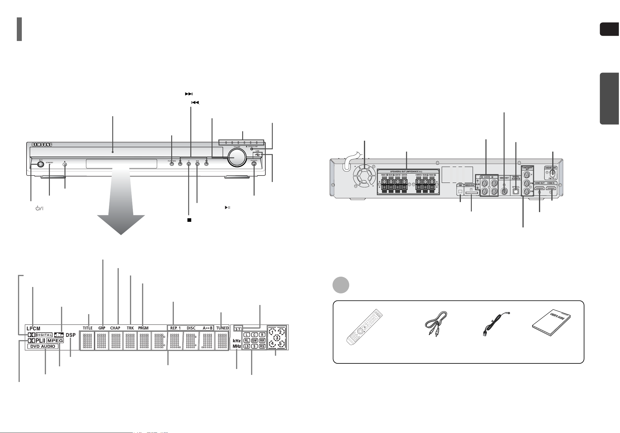
Description
PREPARATION
—Front Panel— —Rear Panel—
Video Cable
(AH39-40001V)
Remote Control
(AH59-01643F)
FM Antenna
(AH42-00017A)
Accessories
User's Manual
(AH68-01834A)
10
DOLBY DIGITAL indicator
LINEAR PCM indicator
DOLBY PLll indicator
DVD AUDIO indicator
MPEG indicator
DSP indicator
TITLE
indicator
GROUP indicator
PROGRAM indicator
CHAPTER indicator
DISC(1~5)
indicator
TRACK indicator
REPEAT indicator
TUNED indicator
STEREO indicator
RADIO FRE-
QUENCY
indicator
System Status Display
SPEAKER indicator
DTS
indicator
Power ( ) button
Standby indicator
Remote Control Sensor
Function button
Headphone Jack
USB Port
Disc Tray
Open/
Close button
Direct Play buttons
Volume control
Tuning Down & Skip ( ) buttons
Tuning Up & Skip ( ) buttons
Play/Pause ( ) button
Stop ( ) button
FM Antenna Connector
External Audio
Input Connectors
5.1 Channel Speaker
Output Terminals
TX Card Connector
XM Antenna Connector
HDMI OUT Port
HDMI IN Port
External Digital Optical
Input Connector
Use this to connect external equipment
capable of digital output.
Cooling Fan
COMPONENT VIDEO OUTPUT
Connectors
Connect a TV with component video inputs
to these jacks.
Video Output Connector
Connect the TV's video input jacks
(VIDEO IN) to the VIDEO OUT connector.
ENG
12
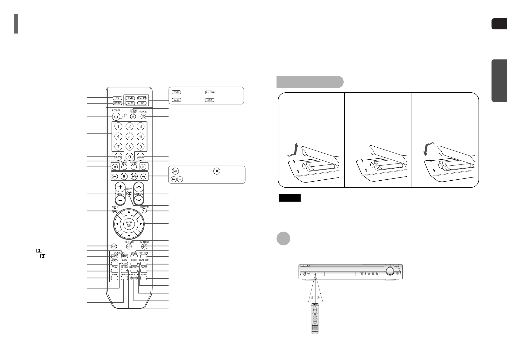
Insert Remote Batteries
The remote control can be used up to approximately 23 feet/7 meters in a straight line. It can also be
operated at a horizontal angle of up to 30° from the remote control sensor.
Range of Operation of the Remote Control
Caution
PREPARATION
Description
Remove the battery
cover on the back of
the remote by pressing
down and sliding the
cover in the direction of
the arrow.
1
Insert two 1.5V AAA
batteries, paying attention to the correct
polarities (+ and –).
2
Replace the battery
cover.
3
Follow these precautions to avoid leaking or cracking cells:
•
Place batteries in the remote control so they match the polarity:(+) to (+)and (–)to (–).
•
Use the correct type of batteries.Batteries that look similar may differ in voltage.
•
Always replace both batteries at the same time.
•
Do not expose batteries to heat or flame.
—Remote Control—
11
PL II MODE button
VOLUME button
MENU button
POWER button
TV button
DVD Receiver button
CANCEL button
REPEAT button
Number(0~9) buttons
TV/VIDEO, DISC SKIP button
OPEN/CLOSE button
Cursor/Enter button
DSP/EQ button
DIGEST button
EZ VIEW button
SLIDE MODE button
HDMI AUDIO button
LOGO button
SD/HD button
RETURN button
SOUND EDIT button
TEST TONE button
AUDIO, XM SEARCH button
MUTE button
INFO button
TUNING/CH button
ZOOM button
FM/XM MEMORY button
SLOW, MO/ST button
DIMMER button
REMAIN button
STEP button
SEARCH buttons
SUB TITLE, XM DISPLAY button
PL II EFFECT button
Play/Pause button
Tuning Preset/CD Skip button
Stop button
DVD button
FM/XM button
AUX button
USB button
SLEEP button
ENG
Rear Speakers
•
Place these speakers behind your listening position.
•
If there isn't enough room, place these speakers so they face each
other.
•
Place them about 60 to 90cm (2 to 3feet) above your ear, facing
slightly downward.
*
Unlike the front and center speakers, the rear speakers are used
to handle mainly sound effects and sound will not come from
them all the time.
Subwoofer
•
The position of the subwoofer is not so critical.
Place it anywhere you like.
Front Speakers
•
Place these speakers in front of your listening position, facing inwards (about 45°) toward you.
•
Place the speakers so that their tweeters will be at
the same height as your ear.
•
Align the front face of the front speakers with the
front face of the center speaker or place them
slightly in front of the center speakers.
Center Speaker
•
It is best to install it at the same height as the front
speakers.
•
You can also install it directly over or under the TV.
Position of the Home Theater
•
Place it on a stand, cabinet shelf, or under the
TV stand.
Selecting the Listening Position
The listening position should be located about 2.5 to 3
times the distance of the TV's screen size away from the
TV. Example: For 32" TVs 2~2.4m (6~8 feet)
For 55" TVs 3.5~4m (11~13 feet)
13
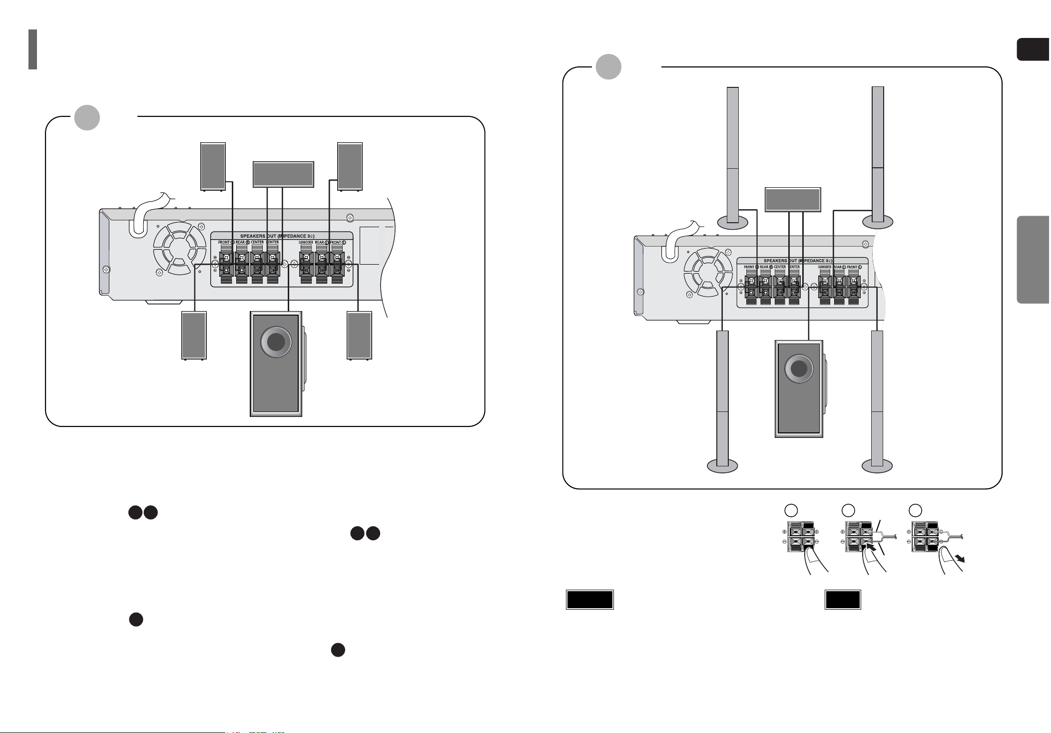
Before moving or installing the product, be sure to turn off the power and disconnect the power cord.
R
L
C
SR
SL
SW
Connecting the Speakers
Rear Speaker (R)
Front Speaker (R)
Subwoofer
Center Speaker
Rear Speaker (L)
Front Speaker (L)
HT-Q80
14
CONNECTIONS
Rear Speaker (R)
Front Speaker (R)
Subwoofer
Center Speaker
Rear Speaker (L)
Front Speaker (L)
Press and hold the terminal tab.
Insert the speaker cord.
Release your finger.
1
2
3
12 3
Red
Black
HT-TQ85
•
Do not let children play with or near the speakers.
They could get hurt if a speaker falls.
•
When connecting the speaker wires to the speakers,
make sure that the polarity (+/–) is correct.
Caution
•
If you place a speaker near your TV set,
screen color may be distorted because of
the magnetic field generated by the speaker. If this occurs, place the speaker away
from your TV set.
Note
ENG
15
Front Speaker (R)
Rear Speaker (L)
Subwoofer
Center Speaker
Front Speaker (L)
Rear Speaker (R)
TX card
WIRELESS RECEIVER MODULE
Front Speaker (R)
Rear Speaker (L)
Subwoofer
Center Speaker
Front Speaker (L)
Rear Speaker (R)
WIRELESS RECEIVER MODULE
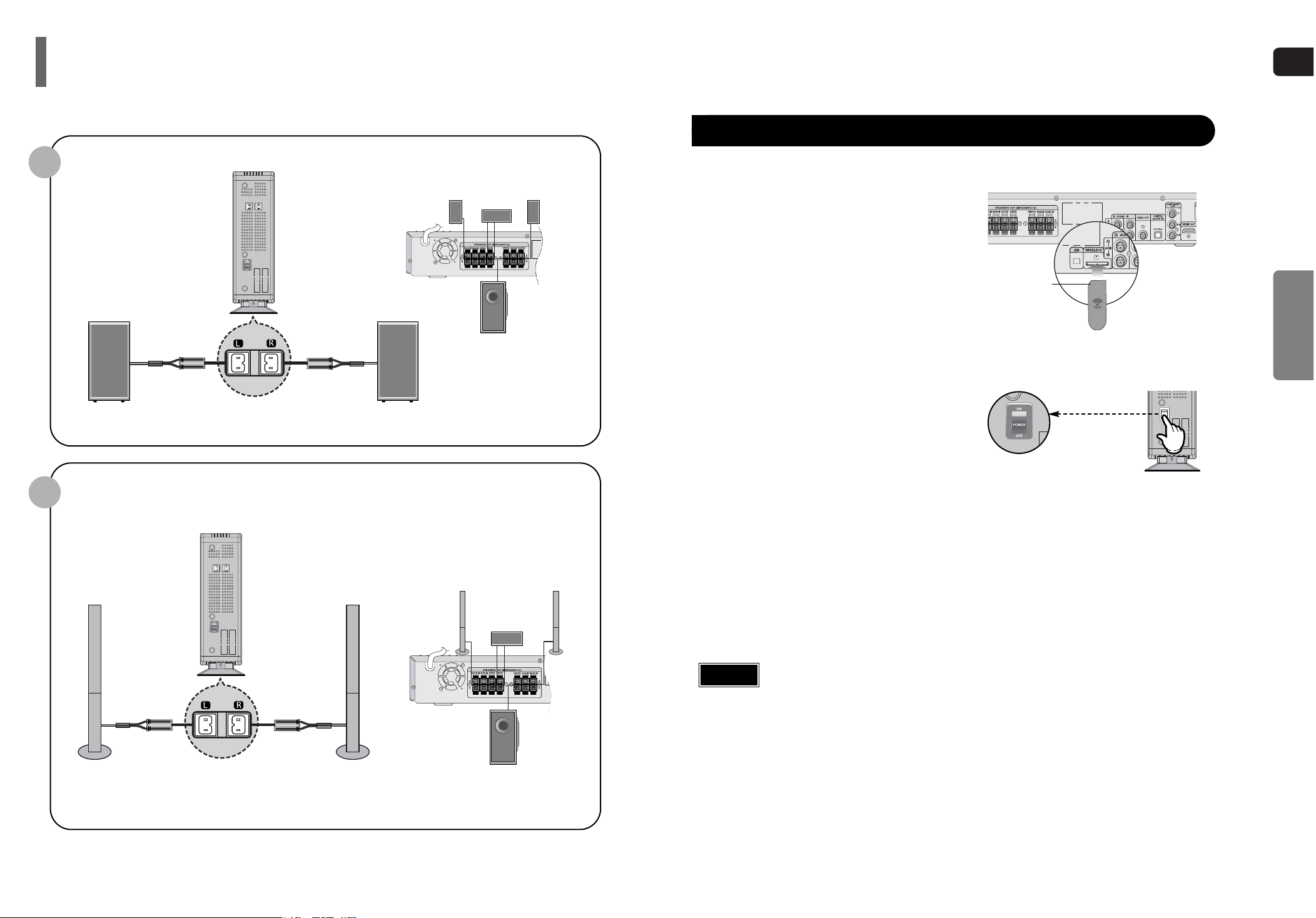
Connect the front, center and
subwoofer speakers, referring to page 14.
Insert the TX card into the TX card
connection port on the back of the
main unit.
•
Hold the TX card so that the slanted side faces leftward and insert the card into the port.
•
The TX card enables communication between the
main unit and the wireless receiver.
Connect the left and right rear
speakers to the wireless receiving
module.
Plug the power cord of the wireless
receiving module in the wall outlet and
switch the power switch ‘ON’.
1
2
3
4
To connect the rear speakers wirelessly, you have to additionally purchase the wireless receiving module and
TX card from your Samsung retailer.
Connecting the optional Wireless Receiving Amplifier
16
CONNECTIONS
•
Do not insert a card other than the TX card dedicated for the product. The product might be damaged or it may not be removed easily.
•
Do not insert the TX card upside down or in reverse direction.
•
Insert the TX card when the main unit is turned off.Inserting the card when it is turned on may cause a problem.
•
If the TX Card is inserted in the main unit, the rear speakers don't output sounds.
Caution
HT-Q80
HT-TQ85
When you have purchased the wireless receiving module (SWA-3000) additionally
Slanted side faces

ENG
WIRELESS RECEIVER MODULE
•
When the wireless receiving module setting is complete, no audio signal is output from the Rear Speaker OUT ports on the back
of the main unit.
•
The wireless receiving antenna is built into the wireless receiver module. Keep the unit away from water and moisture.
•
For optimal listening performance, make sure that the area around the wireless receiver module location is clear of any obstructions.
•
Sound will be heard from the wireless rear speakers in DVD 5.1-CH or Dolby Pro Logic II mode only.
•
In 2-CH mode, no sound will be heard from the wireless rear speakers.
Reset the system if a communication failure occurs, or if the Link indicator (blue LED) on the wireless receiver does
not light up and the "REAR CHK" message blinks on the main unit's display.
Reset the system while the main unit and the wireless receiver module (SWA-3000) are in Power Standby mode.
With the main unit turned off, press and
hold the remote control's REMAIN button
for 5 seconds.
•
Press the button until the POWER( ) indicator lights
up blue. (The indicator will turn off in 1 second.)
With the wireless receiver module
turned on, use a ball point pen or a pair
of tweezers to press the RESET button
on the back of the unit.
•
The Standby/On LED on the front panel of the
wireless receiver module blinks 2 times.
2
1
Turn on the main unit.
•
The Link LED of the wireless receiver module is lit
and the setup is finished.
•
If Power Standby mode continues, repeat Steps 1 to
3 above.
3
Caution
•
Place the wireless receiver module at the rear of the listening position. If the wireless receiver module is too close to the main
unit, some sound interruption may be heard due to interference.
•
If you use a device such as a microwave oven, wireless LAN Card, Bluetooth equipment, or any other device that uses the same
frequency (2.4GHz) near the system, some sound interruption may be heard due to interference.
•
The transmission distance of radio wave is about 33 feet, but may vary depending on your operating environment.
If a steel-concrete wall or metallic wall is between the main unit and the wireless receiver module, the system may not operate at
all, because the radio wave cannot penetrate metal.
Note
Resetting Wireless Communication
Choose one of the two methods for connecting to a TV.
Connecting the Video Out to TV
- Connect the supplied video cable from the VIDEO OUT jack on the back panel of the system
to the VIDEO IN jack on your TV.
Composite Video
.......
(Good Quality)
METHOD 1
- If your television is equipped with Component Video inputs, connect a component video cable
(not supplied) from the Pr, Pb and Y jacks on the back panel of the system to the corresponding
jacks on your TV.
Component
.......
(Better Quality)
METHOD 2
- Connect the HDMI out to the HDMI input on your TV.
HDMI
.......
(Best Quality)
METHOD 3
•
This product operates in Progressive scan mode(480p Only ) for Component Output.
•
If the TV only supports a resolution of 576i(480i), the screen may be divided into 2 screens, or display nothing.
•
After making the video connection, set the Video input source on your TV to match the corresponding Video output (HDMI, Component or Composite) on your Home theater. See your TV
owner's manual for more information on how to select the TV's Video Input source.
Note
TV
METHOD 2
(supplied)
METHOD 1
METHOD 3
17 18
CONNECTIONS
Connecting the optional Wireless Receiving Amplifier

ENG
HDMI (High-Definition Multimedia Interface) is a next generation TV-type digital interface specification
that enables transmitting digital video and audio over a single cable. In addition, it enables you to
enjoy multi-channel digital audio.
Connecting the HDMI IN/OUT
Connect the HDMI OUT Port of this unit and the HDMI IN Port of your TV.
2
Press AUX on the remote control to select ‘HDMI IN.
•
Each time the button is pressed, the selection changes as follows:
DIGITAL IN➝ AUX 1 ➝ AUX 2 ➝ HDMI IN.
•
You can also use the FUNCTION button on the main unit.
The mode switches as follows: DVD/CD ➝ DIGITAL IN ➝ AUX 1 ➝ AUX 2 ➝ HDMI IN ➝ USB ➝ FM➝ XM.
Connect the HDMI IN Port of this unit and the HDMI OUT Port of a set-top box
or the DVD player.
1
3
Set-top box or
DVD player
TV
•
When this unit is turned off, no HDMI video or audio signal is output from this unit.
•
In the HDMI IN Function, the video resolution switch button (SD/HD) does not work.
•
When the output from an external device, which is connected to this device, is DVI, no audio will be output. In this case, you can listen to the digital audio by connecting the Optical OUT of the source device
and the Optical IN of this device, even if the source device and this device is connected through DVI
interface.
Note
19 20
What is HDMI (High Definition Multimedia Interface)?
This device transmits DVD video signal digitally without the process of converting to analog.
You can get sharper digital pictures by connecting the video to your TV using an HDMI connection cable.
HDMI Function
HDMI Audio ON/OFF function
•
The audio signals transmitted over the HDMI Cable can be toggled
ON/OFF.
Press the HDMI AUDIO button on the remote con-
trol.
•
This toggles between “AUDIO ON” and “AUDIO OFF” on the display.
•
AUDIO ON : Both video and audio signals are transmitted over the
HDMI connection cable, and audio is output is through your TV speakers only.
•
AUDIO OFF : Video is transmitted over the HDMI connection cable only,
and audio is output through the home theater speakers only.
• The default setting value of this product is HDMI AUDIO OFF.
• HDMI AUDIO is automatically down-mixed to 2ch for TV speakers.
• If you turn the unit off and on, or switch functions when the HDMI
AUDIO is set to ON, the HDMI AUDIO is automatically set to OFF.
Note
CONNECTIONS
21
ENG
22
CONNECTIONS
HDMI Function
Resolution Selection
•
This function allows the user to select screen resolution for HDMI output.
In Stop mode, press and hold the SD/HD (Standard
Definition/High Definition)button on the remote control.
•
Resolutions available for the HDMI output are 480P, 720P and 1080i.
•
SD(Standard Definition) resolution is 480p and HD(High Definition) resolution is 720p/1080i.
Example: If the TV supports resolution up to 480p:
Press the SD/HD button.
•
A 480p video signal is output through the HDMI output.
•
If the TV does not support the configured resolution, you will not be able
to see the picture properly.
• You do not have to make separate adjustments, since the Home
Theater and TV will be automatically adjust themselves to the optimal resolution and aspect ratio if connected to HDMI. (If the TV is
an HDTV and has an HDMI Input jack, output is automatically converted to 1080i resolution (if supported by the TV).)
• For component video output, only 480P is supported.
• When both HDMI and COMPONENT jacks are connected, COMPO-
NENT video is not displayed.
• See your TV owner's manual for more information on how to select
the TV's Video Input source.
Note
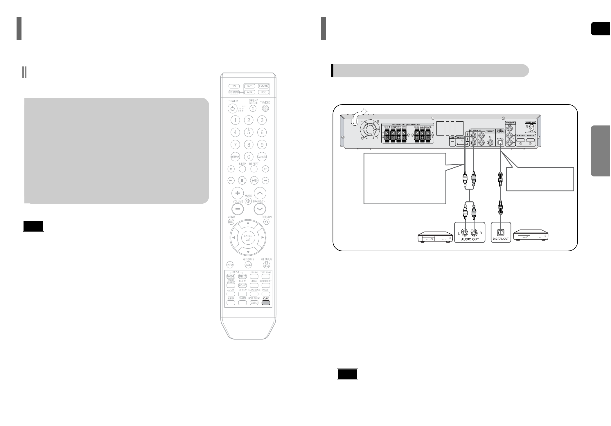
Connecting External Components
Connect AUX (Audio) In on the Home Theater to Audio Out on the external analog component.
•
Be sure to match connector colors.
2
Analog signal components such as a VCR.
Press AUX on the remote control to select ‘HDMI IN /DIGITAL IN / AUX1/AUX2’ input.
•
Each time the button is pressed, the selection changes as follows: AUX1 ➝ AUX2➝ HDMI IN➝DIGITAL IN
•
You can also use the FUNCTION button on the main unit.
The mode switches as follows: DVD/CD ➝ DIGITAL IN ➝ AUX1➝ AUX2➝HDMI IN ➝ USB ➝ FM ➝ XM
Connect the Digital Input (OPTICAL) to the Digital Output on the external digital component.
1
3
Example: Digital signal components such as a Set-Top Box or CD Recorder.
Connecting an External Digital / Analog Component
Optical Cable
(not supplied)
Audio Cable
(not supplied)
If the external analog compo-
nent has only one Audio Out,
connect either left or right.
•
You can connect the Video Output jack on your VCR to the TV, and connect the Audio
Output jacks on the VCR to this product.
Note
23
ENG
24
CONNECTIONS
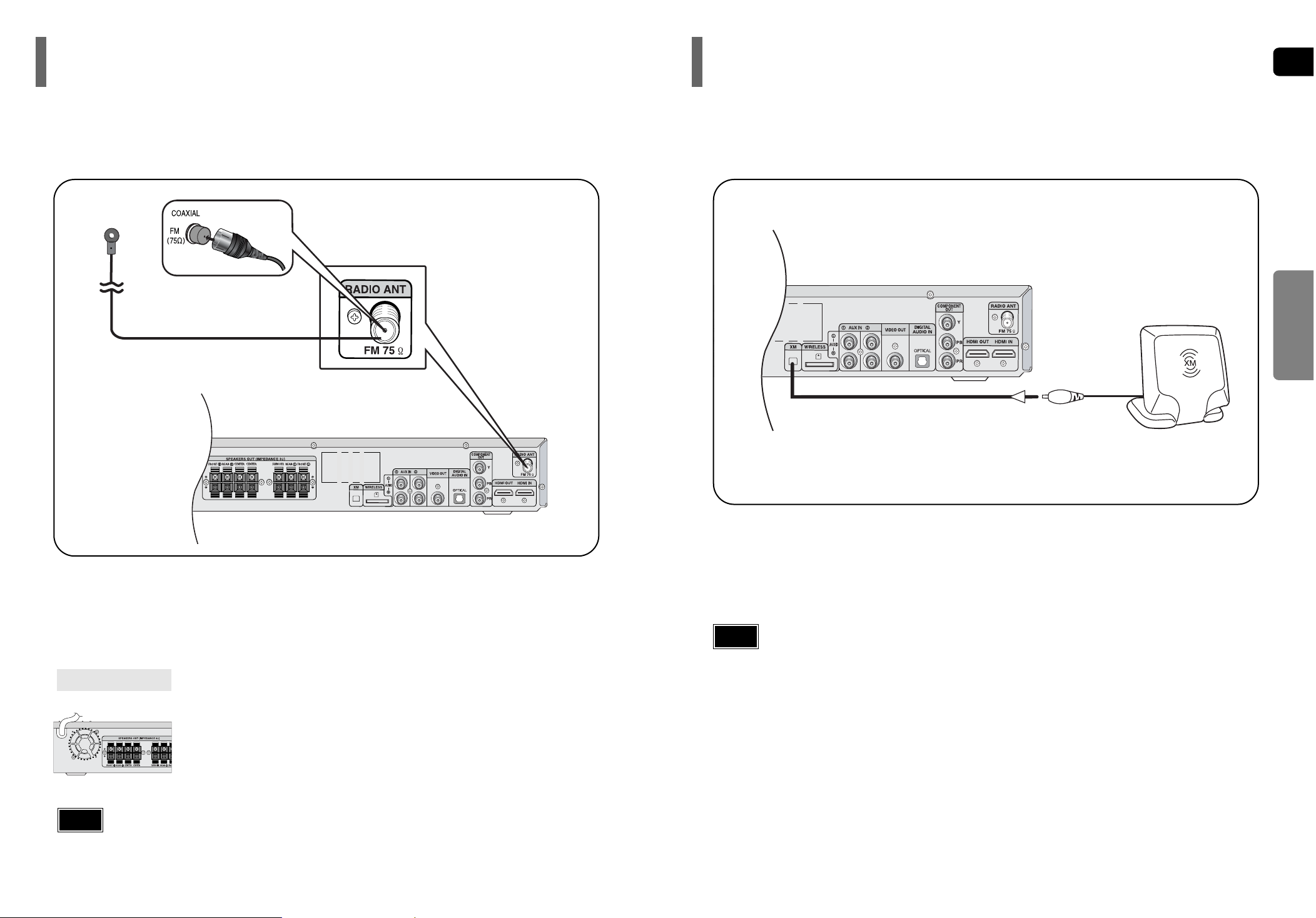
Connecting the FM Antenna
The cooling fan supplies cool air to the unit to prevent overheating.
Please observe the following cautions for your safety.
•
Make sure the unit is well-ventilated. If the unit has poor ventilation, the temperature inside the unit could rise
and may damage it.
•
Do not obstruct the cooling fan or ventilation holes. (If the cooling fan or ventilation holes are covered with a
newspaper or cloth, heat may build up inside the unit and fire may result.)
Cooling Fan
Connect the FM antenna supplied to the FM 75Ω COAXIAL terminal.
Slowly move the antenna wire around until you find a location where reception is good, then fasten it to a wall or other rigid surface.
FM Antenna (supplied)
Connecting an optional XM Satellite Radio Antenna
•
To ensure optimal reception of XM’s satellite signal, the XM Antenna should be placed at or near a southerly facing window with nothing obstructing its path to the sky. You can mount it indoors or outdoors.
•
When making connections, also refer to the operation instructions of the XM Antenna.
•
Depending on your location, the radio signal may be weak or cannot be tuned .
XM Antenna (Sold separately)
Notes
•
This unit does not receive AM broadcasts.
Notes
Connect the XM Antenna(Sold separately) to the XM Antenna Connector on the rear of this unit.
1
2
•
Buttons Enabled for TV Operation: POWER, CHANNEL, VOLUME, TV/VIDEO, and Numeric (0-9) buttons.
•
By default, the remote control is set to work with Samsung TVs.
See page 77 for more information about remote control operation with other manufacturer's TVs.
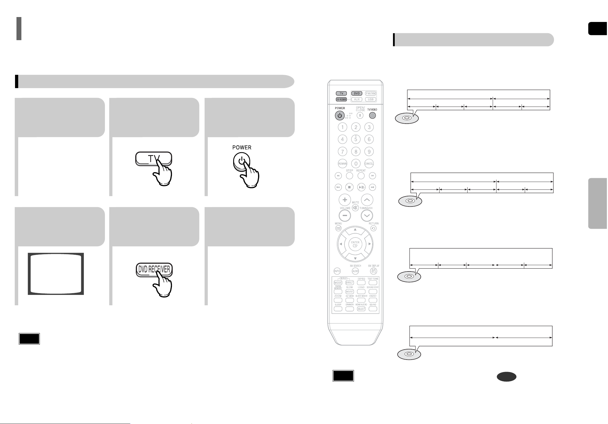
25
23
Press TV button to
set the remote to TV
mode.
Press the POWER
button to turn on your
Samsung TV with this
remote.
56
Press FUNCTION button
on the main unit or DVD
button on the remote to
enable DVD/CD playback.
1
Plug the main unit's
power cord into the
AC power supply.
4
Press DVD RECEIVER
button to switch to
DVD RECEIVER
mode.
Note
Your Home Theater is capable of playing DVD, CD, MP3/WMA and JPEG discs.Depending on the disc you are
using, these instructions may vary slightly. Read the instructions carefully before using.
Before Using Your Home Theater
To Operate your Samsung TV and the Home Theater with the HT-Q80/HT-TQ85's Remote Control
Press TV/VIDEO
button to select
VIDEO mode on
your TV.
ENG
•
In this manual, the instructions marked with "DVD ( )" are applicable
to DVD-VIDEO, DVD-AUDIO, and DVD-R/RW discs.
Where a particular DVD type is mentioned, it is indicated separately.
•
Depending on the content of the disc, the initial screen may appear different.
DVD
Note
26
Groups and tracks (DVD-AUDIO)
•
DVD-audio is divided into several large sections called "groups" and
smaller sections called "tracks". Numbers are allotted to these sections.
These numbers are called "group numbers" and "track numbers".
GROUP 1 GROUP 2
TRACK 1 TRACK 2 TRACK 1 TRACK 2TRACK 3
Titles and chapters (DVD-VIDEO)
•
DVD-video is divided into several large sections called "titles" and smaller
sections called "chapters". Numbers are allotted to these sections.
These numbers are called "title numbers" and "chapter numbers".
TITLE 1 TITLE 2
CHAPTER 1 CHAPTER 2 CHAPTER 1 CHAPTER 2CHAPTER 3
Tracks (Video and music CDs)
•
Video and music CDs are divided into sections called "tracks".
Numbers are allotted to these sections. These numbers are called
"track numbers".
TRACK 1 TRACK 2 TRACK 4 TRACK 5TRACK 3
Files (DivX)
•
DivX is divided into sections called "files".
Numbers are allotted to these sections. These numbers are called
"file numbers".
FILE 1 FILE 2
Disc terminology
VIDEO
OPERATION
 Loading...