

Samsung HT-TKX500 User Manual

THIS APPLIANCE IS MANUFACTURED BY:
AH68-02013P(REV:1.0)
AH68-01660E
REV: 01
ENGInstruction Manual
COMPACT
DIGITAL AUDIO
COMPACT
DIGITAL AUDIO
DIGITAL HOME
CINEMA SYSTEM
HT-TKX500
PREPARATION
Safety Warnings
CAUTION
RISK OF ELECTRIC SHOCK.
DO NOT OPEN
can cause electric shock is present inside this unit.
This symbol alerts you to important operating and
This symbol indicates that dangerous voltage which
TO REDUCE THE RISK OF ELECTRIC
maintenance instructions accompanying the unit.
SHOCK, DO NOT REMOVE REAR COVER.
NO USER SERVICEABLE PARTS INSIDE.
REFER SERVICING TO QUALIFIED
SERVICE PERSONNEL.
CLASS 1 LASER PRODUCT
KLASSE 1 LASER PRODUKT
LUOKAN 1 LASER LAITE
KLASS 1 LASER APPARAT
PRODUCTO LASER CLASE 1
CLASS 1 LASER PRODUCT
This Compact Disc player is classied as a CLASS 1
LASER product.
Use of controls, adjustments or performance of procedures other than
those specied herein may result in hazardous radiation exposure.
CAUTION- INVISIBLE LASER RADIATION WHEN OPEN AND
INTERLOCKS DEFEATED, AVOID EXPOSURE TO
BEAM.
WARNING : To reduce the risk of fire or electric shock, do not expose this appliance to rain or moisture.
CAUTION : TO PREVENT ELECTRIC SHOCK, MATCH WIDE BLADE OF PLUG TO WIDE SLOT, FULLY INSERT.
This apparatus shall always be connected to a AC outlet with a protective grounding connection.
•
To disconnect the apparatus from the mains, the plug must be pulled out from the mains socket, therefore the mains
•
plug shall be readily operable.
CAUTION
Apparatus shall not be exposed to dripping or splashing and no objects lled with liquids, such as vases, shall be
•
placed on the apparatus.
The Mains plug is used as a disconnect device and shall stay readily operable at any time.
•
This marking shown on the product or its literature, indicates that it should not be
disposed with other household wastes at the end of its working life.
To prevent possible harm to the environment or human health from uncontrolled waste
disposal, please separate this from other types of wastes and recycle it responsibly to
promote the sustainable reuse of material resources.
Household users should contact either the retailer where they purchased this
product, or their local government ofce, for details of where and how they
can take this item for environmentally safe recycling.
Business users should contact their supplier and check the terms and
conditions of the purchase contract.
This product should not be mixed with other commercial wastes for disposal.
2 3
ENG
PREPARATION
Precautions
DVD
HOME
CINEMA
SYSTEM HT-TX500
DVD
HOME CINEMA
SYSTEM HT-TX500
DVD
HOME CINEMA
SYSTEM HT-TX500
Phones
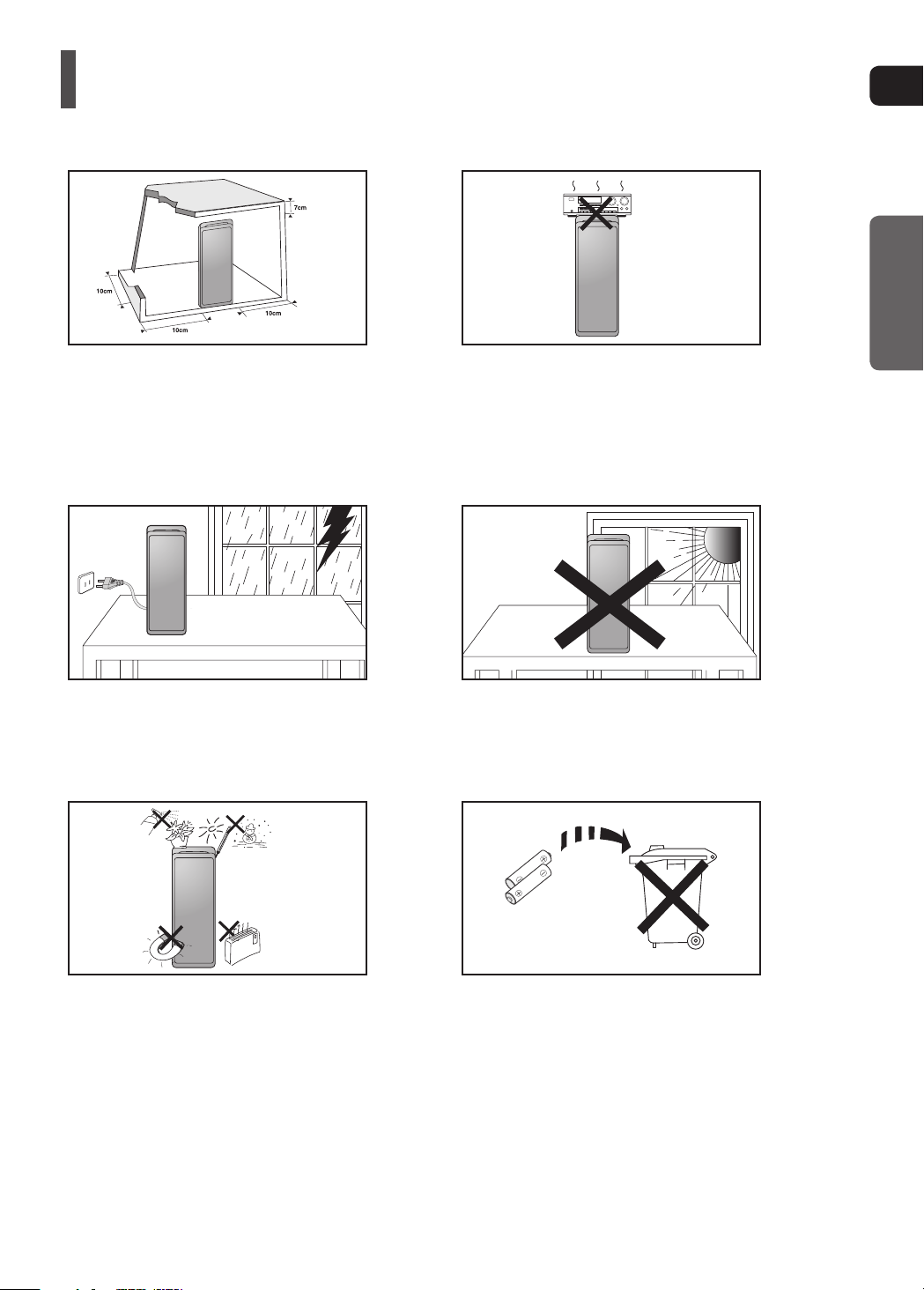
Ensure that the AC power supply in your house complies with the identication sticker located on the back of your player or subwoofer.
Install your player or subwoofer horizontally, on a suitable base (furniture), with enough space around it for ventilation (7.5~10cm). Make
sure the ventilation slots are not covered. Do not stack anything on top of the player or subwoofer. Do not place the player or subwoofer
on ampliers or other equipment which may become hot. Before moving the player, ensure the disc insert hole is empty. This player is
designed for continuous use. Switching off the DVD player to the stand-by mode does not disconnect the electrical supply. In order to
disconnect the player completely from the power supply, remove the main plug from the wall outlet, especially when left unused for a
long period of time.
During thunderstorms, disconnect AC main plug from
the wall outlet. Voltage peaks due to lightning could
damage the unit.
Protect the player from moisture (i.e. vases),
and excess heat (e.g.replace) or equipment
creating strong magnetic or electric elds
(i.e.speakers...). Disconnect the power cable
from the AC supply if the player malfunctions.
Your player is not intended for industrial use.
Use of this product is for personal use only.
Condensation may occur if your player or disc
has been stored in cold temperatures.
If transporting the player during the winter,
wait approximately 2 hours until the unit has
reached room temperature before using.
Do not expose the unit to direct sunlight or
other heat sources.
This could lead to overheating and malfunction
of the unit.
The batteries used with this product contain
chemicals that are harmful to the environment.
Do not dispose of batteries in the general
household trash.

Features
Multi-Disc Playback & FM Tuner
The HT-TKX500 combines the convenience of multi-disc playback capability, including DVD-VIDEO, CD, MP3-CD,
WMA-CD, DivX, CD-R/RW, and DVD R/RW, with a sophisticated FM tuner,
all in a single player.
USB HOST Function support
You can connect and play les from external USB storage devices such as MP3 players, USB ash memory, etc.
using the Home Theater's USB HOST function.
Dolby Pro Logic II
Dolby Pro Logic II is a form of multi-channel audio signal decoding technology that improves upon existing
Dolby Pro Logic.
DTS (Digital Theater Systems)
DTS is an audio compression format developed by Digital Theater Systems Inc. It delivers full-frequency
5.1 channel sound.
TV Screen Saver Function
If the main unit remains in stop mode for 3 minutes, Samsung logo appears on TV screen.
The HT-TKX500 automatically switches itself into the power saving mode after 20 minutes in the Screen Saver
mode.
Power Saving Function
The HT-TKX500 automatically shuts itself off after 20 minutes in Stop mode.
HDMI
HDMI transmits DVD video and audio signals simultaneously, and provides a clearer picture.
The 1080p(Full HD) resolution provides even clearer pictures.
Anynet+ (HDMI-CEC) Function
Anynet+ is a function that can be used to operate the main unit using a Samsung TV remote control, by connecting the
Home Theater to a SAMSUNG TV using an HDMI Cable. (This is only available with SAMSUNG TVs that support
Anynet+.)
Simple Touch Button
The touch button on this player has equipped with a sensor activated by a physical contact, which allows you to operate
the button with simple touch.
4 5

ENG
PREPARATION
PREPARATION
Safety Warnings ..................................................2
Precautions..........................................................3
Features ..............................................................4
Notes on Discs ....................................................6
Description...........................................................8
CONNECTIONS
Speaker Installation ...........................................12
Installing the DVD player ...................................14
Connecting the Speakers ..................................16
Connecting the Wireless Receiving Amplier .... 19
Connecting the Video Out to your TV ..........................21
HDMI Function
Connecting Audio from External Components ..23
Connecting the FM Antenna .............................. 26
.....................................................22
OPERATION
Before Reading the User's Manual ....................27
Before Using Your Home Theater .....................28
Disc Playback ....................................................29
MP3/WMA-CD Playback ...................................30
JPEG File Playback ........................................... 31
DivX Playback ...................................................32
Using the Playback Function .............................34
Displaying Disc Information ...........................34
Fast Playback ................................................35
Slow Playback ................................................35
Skipping Scenes/Songs .................................36
Repeat Playback ............................................37
To Select a Repeat Playback Mode in the
Disc Information Screen .................................38
A-B Repeat Playback .....................................39
Step Function .................................................39
Angle Function ...............................................40
Zoom (Screen Enlarge) Function ...................40
Audio Language Selection Function ..............41
Subtitle Language Selection Function ...........41
Moving Directly to a Scene/Song ...................42
Using the Disc Menu ......................................43
Using the Title Menu ......................................43
Playing Media Files using the USB
Host Feature ...................................................... 44
SETUP
Settings..............................................................46
Setting the Language ....................................46
Setting TV Screen type..................................47
Setting Parental Controls (Rating Level) .......48
Setting the Password.....................................48
Setting the Wallpaper ....................................49
To Select One of the 3 Wallpaper Settings
you've made ..................................................49
DivX (R) registration ......................................50
Setting the Speaker Mode .............................50
Setting the Delay Time ..................................51
Setting the Test Tone ....................................52
Setting the Audio ...........................................53
Setting the DRC
(Dynamic Range Compression) ....................54
Setting the AV SYNC.....................................54
Setting the HDMI Audio .................................55
Sound Field (DSP)/EQ Function....................56
Dolby Pro Logic II Mode ................................57
Dolby Pro Logic II Effect ................................57
KARAOKE
Karaoke .............................................................58
Playing DVD-OK Discs ..................................58
Wireless Microphone Operation ....................58
Reserving Accompaniment Music .................60
Priority Playing Accompaniment Music .........60
DVD-OK Repeat Play ....................................61
Favorite Song Function .................................61
Search Song Function ...................................63
Key Control ....................................................65
Tempo Control ...............................................65
Male-Female Key Control ..............................66
Setting the Chorus ......................................... 66
Setting the Fanfare ........................................67
Setting the Average Score.............................67
Setting the Shadow .......................................67
MISCELLANEOUS
Listening to Radio .............................................. 68
About RDS broadcasting ...................................70
Convenient Functions ........................................ 72
Operating a TV with the Remote Control...........73
Troubleshooting ................................................. 75
Cautions on Handling and Storing Discs ...........77
Language Code List ..........................................78
USB Host Feature Supported Products.............79
Specications ....................................................80
1 6
~
COMPACT
DIGITAL AUDIO
COMPACT
DIGITAL AUDIO
Notes on Discs
DVD (Digital Versatile Disc) offers fantastic audio and video, thanks to Dolby
Digital surround sound and MPEG-2 video compression technology.
Now you can enjoy these realistic effects in the home, as if you were in a movie
theater or concert hall.
DVD players and the discs are coded by region. These regional codes must match
in order for the disc to play. If the codes do not match, the disc will not play.
The Region Number for this player is given on the rear panel of the player.
(Your DVD player will only play DVDs that are labeled with identical region codes.)
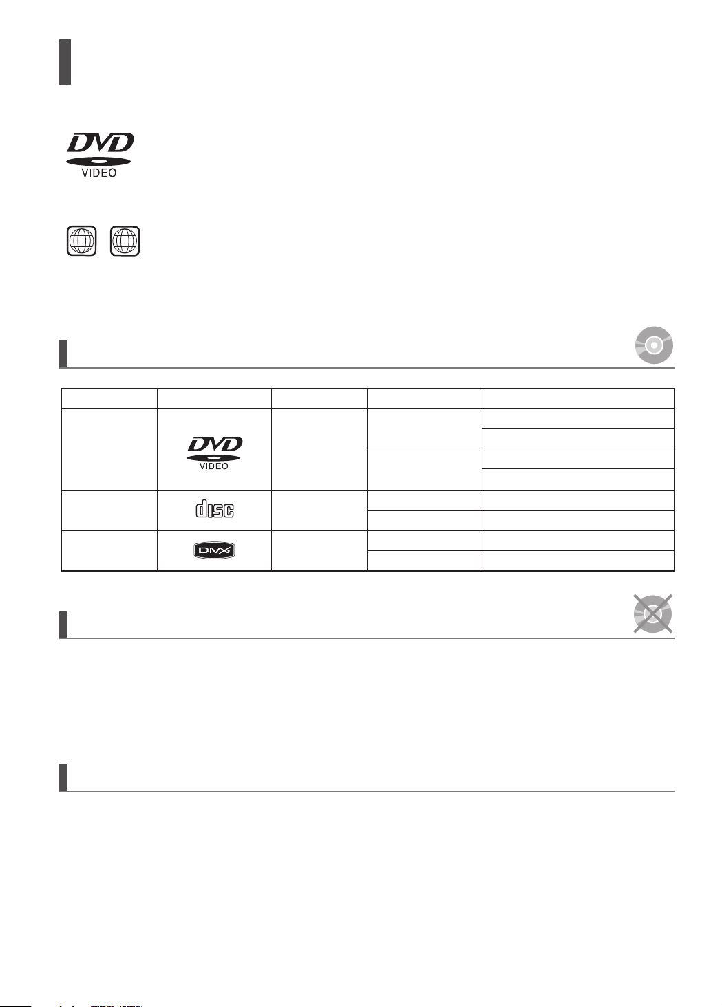
Playable Discs
Disc Type
DVD-VIDEO
AUDIO-CD
Divx
Mark (Logo)
Recorded Signals
Audio + Video
Audio
Audio + Video
Disc Size Max. Playing Time
12cm
8cm
12cm
8cm
12cm
8cm
Approx. 240 min. (single-sided)
Approx. 480 min. (double-sided)
Approx. 80 min. (single-sided)
Approx. 160 min. (double-sided)
74 min.
20 min.
74 min.
20 min.
Do not use the following types of disc!
LD, CD-G, CD-I, CD-ROM and DVD-ROM discs cannot be played on this player.
•
If such discs are played, a <WRONG DISC FORMAT> message appears on the TV screen.
DVD discs purchased abroad may not play on this player.
•
If such discs are played, a <CAN'T PLAY THIS DISC PLEASE,CHECK REGION CODE> message
appears on the TV screen.
Copy Protection
Many DVD discs are encoded with copy protection. Because of this, you should only connect your
•
DVD player directly to your TV, not to a VCR. Connecting to a VCR results in a distorted
picture from copy-protected DVD discs.
This product incorporates copyright protection technology that is protected by methods claims of certain U.S.
•
patents and other intellectual property rights owned by Macrovision Corporation and other rights owners.
Use of this copyright protection technology must be authorized by Macrovision Corporation, and is intended
for home and other limited viewing uses only unless otherwise authorized by Macrovision Corporation.
Reverse engineering or disassembly is prohibited.
6 7

ENG
PREPARATION
Disc Recording Format
This product does not support Secure (DRM) Media les.
CD-R Discs
Some CD-R discs may not be playable depending on the disc recording device (CD-Recorder or PC) and the condition
•
of the disc.
Use a 650MB/74 minute CD-R disc.
•
Do not use CD-R discs over 700MB/80 minute as they may not be played back.
Some CD-RW (Rewritable) media, may not be playable.
•
Only CD-Rs that are properly <closed> can be fully played. If the session is closed but the disc is left open, you may not
•
be able to fully play the disc.
CD-R MP3 Discs
Only CD-R discs with MP3 les in ISO 9660 or Joliet format can be played.
•
MP3 le names should be 8 characters or less in length and contain no blank spaces or special characters (. / = +).
•
Use discs recorded with a compression/decompression data rate greater than 128Kbps.
•
Only les with the <mp3> and extensions can be played.
•
Only a consecutively written multisession disc can be played. If there is a blank segment in the Multisession disc,
•
the disc can be played only up to the blank segment.
If the disc is not closed, it will take longer to begin playback and not all of the recorded les may be played.
•
For les encoded in Variable Bit Rate (VBR) format, i.e. les encoded in both low bit rate and high bit rate
•
(e.g., 32Kbps ~ 320Kbps), the sound may skip during playback.
A maximum of 500 tracks can be played per CD.
•
A maximum of 300 folders can be played per CD.
•
CD-R JPEG Discs
Only les with the <jpg> extensions can be played.
•
If the disc is not closed, it will take longer to start playing and not all of the recorded les may be played.
•
Only CD-R discs with JPEG les in ISO 9660 or Joliet format can be played.
•
JPEG le names should be 8 characters or less in length and contain no blank spaces or special characters (. / = +).
•
Only a consecutively written multisession disc can be played. If there is a blank segment in the multisession disc,
•
the disc can be played only up to the blank segment.
A maximum of 9,999 images can be stored on a single CD.
•
When playing a Kodak/Fuji Picture CD, only the JPEG les in the picture folder can be played.
•
Picture discs other than Kodak/Fuji Picture CDs may take longer to start playing or may not play at all.
•
DVD R/RW, CD-R/RW DivX Discs
Since this product only provides encoding formats authorized by DivX Networks, Inc., a DivX le created by the user might
•
not play.
Software updates for incompatible formats are not supported.
•
(Example: QPEL, GMC, resolution higher than 800 x 600 pixels, etc.)
Sections with a high frame rate might not be played while playing a DivX le.
•
For more information about the formats authorized by DivX Networks, Inc., please visit <www.divxnetworks.net>.
•
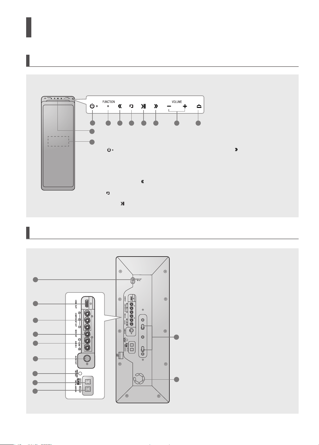
Description
Front Panel
Rear Panel
1
2
3
4
5
6
7
8
9
2
1
9
10
1.
Power ( ) button
(Press and hold for more than 1 second)
2. Function button
3. Tuning Down & Skip ( ) button
4. Stop ( ) button
5. Play/Pause ( ) button
3 4
5
6
7
10
11
8
6.
Tuning Up & Skip ( ) button
7. Volume Control button
8. Eject button
(Press and hold for more than 1 second)
9. Disc Insert Hole
10. Display
1. FM 75Ω COAXIAL Jack
2. HDMI OUT Jack
3. Component Video Output Jacks
Connect a TV with Component video
inputs to these jacks.
4. Video Output Jack Connect your TV's
Video Input jack (VIDEO IN) to the
VIDEO OUT Jack on this unit.
5. AUX IN 2 Jacks (L/R)
6. Audio Output Jack
7. WIRELESS MIC ANT Jack
8. External Digital Optical Input Jack 1
Use this to connect external equipment
capable of digital output.
9. External Digital Optical Input Jack 2
Use this to connect external equipment
capable of digital output.
10. Stand Fix Hole
11. Cooling Fan
.
8 9
ENG
PREPARATION
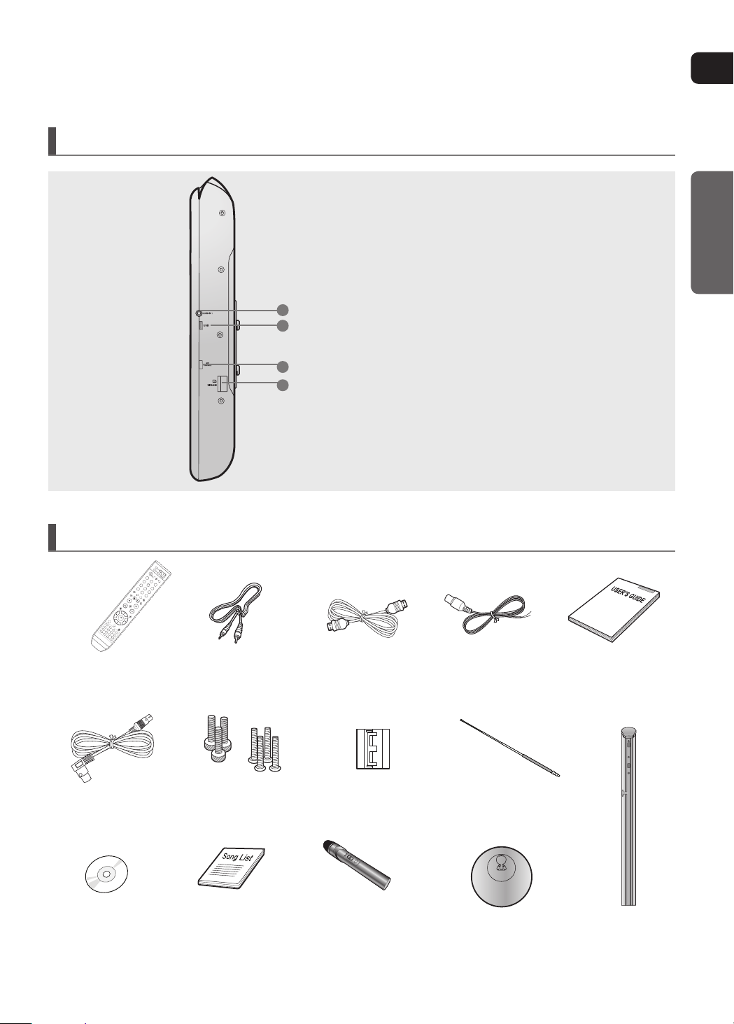
Side Panel
Accessories
Remote Control
Video Cable
1
2
2.
USB Port
3. MIC Channel Select Switch
1. AUX IN 1 Jack
3
HDMI Cable
4. TX Card Connection(WIRELESS)
FM Antenna
User's Manual
Screw(Large) : 3EA
System Cable
DVD KARAOKE
DISC
• For more information about the speaker system, refer to page 12.
Screw(Small) : 4EA
SONG LIST BOOK4WIRELESS MICROPHONE
& BATTERY (1.5VX 3EA)
Core
(Toroidal Ferrite Core)
WIRELESS MICROPHONE
ANTENNA
Stand basel
Stand
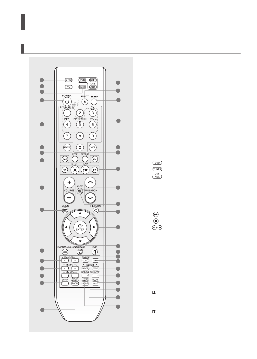
Description (Con’t)
Remote Control
1
2
3
4
5
6
7
8
9
10
11
12
13
14
15
16
17
18
19
20
21
22
23
24
25
26
27
28
29
30
31
32
33
34
35
36
37
1. DVD RECEIVER button
2. TV button
3. TV/VIDEO button
4. POWER button
5. Number (0~9) buttons
6. RESERVE button
7. STEP button
8. Tuning Preset/CD Skip buttons
9. VOLUME button
10. MENU button
11. FAVORITE SONG, AUDIO button
12. KEY CONTROL buttons
13. TEMPO buttons
14. MIC VOL buttons
15. ECHO button
16. MALE/ FEMALE, ZOOM button
17.
DVD button
TUNER button
USB, AUX button
EJECT button
18.
19. SLEEP button
20. RDS Selection buttons
21. CANCEL button
22. REPEAT button
PLAY/PAUSE button
23.
STOP button
SEARCH buttons
24. TUNING/CH button
25. MUTE button
26. RETURN button
27. Cursor/ENTER
button
28. SEARCH SONG, SUBTITLE button.
29. EXIT button
30. DIMMER button / BUZZER OFF button /
HOLD button, LOGO button
31. INFO button
PL II EFFECT button
32.
33. SOUND EDIT button
34. SLOW, MO/ST button
PL II MODE button
35.
36. DSP/EQ button
37. TUNER MEMORY, SD(Standard Definition) /
HD(High Definition) button
10 11
ENG
PREPARATION
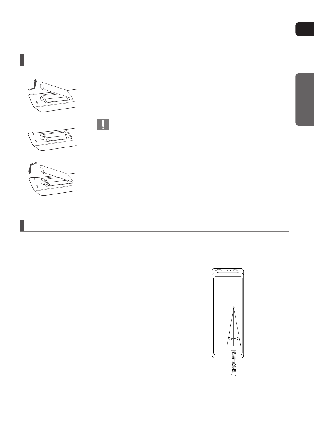
Insert Remote Batteries
1 Remove the battery cover in the direction of the arrow.
2 Insert two 1.5V AAA batteries, paying attention to the correct polarities
(+ and –).
3 Replace the battery cover.
Follow these precautions to avoid leaking or cracking cells:
•
•
•
•
Place batteries in the remote control so they match the polarity :
(+) to (+) and (–) to (–).
Use the correct type of batteries.Batteries that look similar may differ in
voltage.
Always replace both batteries at the same time.
Do not expose the batteries to heat or a ame.
Operation Range of the Remote Control
The remote control can be used up to approximately 7 meters(23 feet) in a straight line. It can also be operated
at a horizontal angle of up to 30° from the remote control sensor.
Speaker Installation
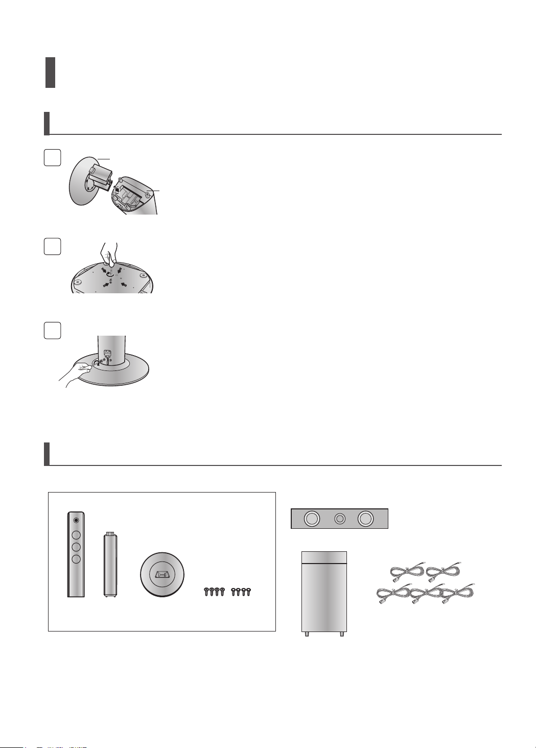
How to Install the Speaker and the Stand
1
2
3
STAND
BASE
STAND
Turn the stand upside down and mount it on the
1
stand base.
Tighten 4(Black) screws on the bottom side of the
2
stand base.
Place the stand on the floor and tighten 2(Silver)
3
on the back of the stand.
Speaker Packages
Please conrm that all the following contents are included in the package.
Front/Rear Speaker
Center Speaker
SPEAKER
(4EA)
* Front speakers and rear speakers are packaged
separately as shown in the diagram.
STAND
(4EA)
STAND BASE
(4EA)
12 13
SCREW (16EA): BLACK
SCREW (16EA): SILVER
Subwoofer Speaker Speaker Cable (5EA)
ENG
CONNECTIONS
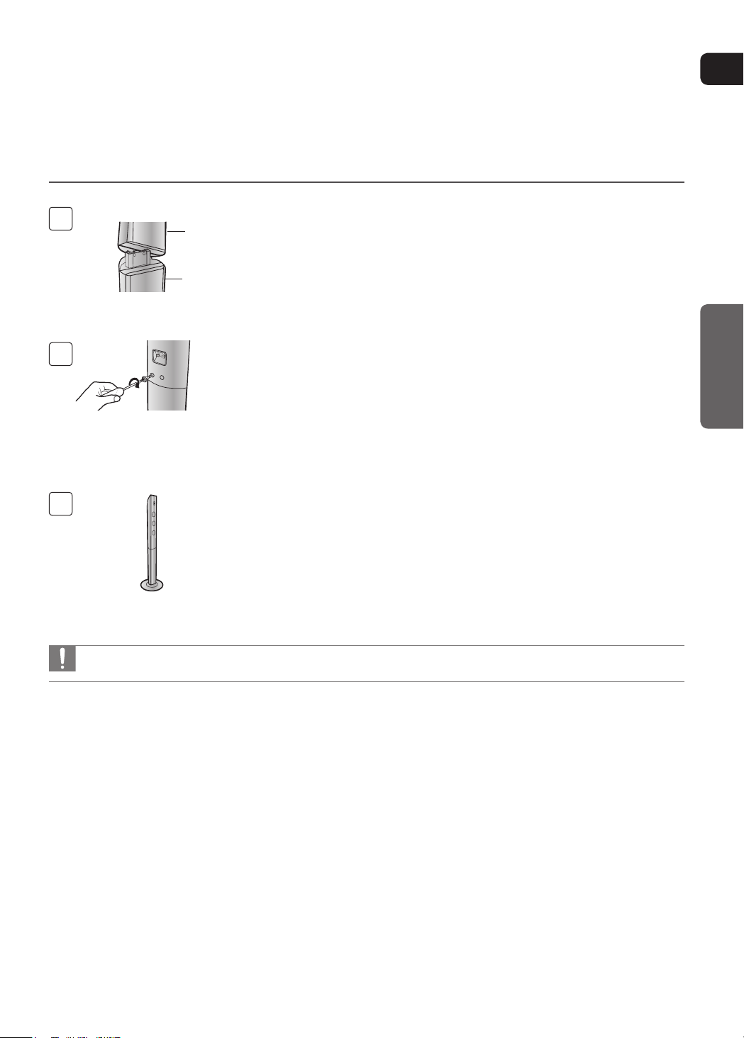
4
SPEAKER
STAND
5
Mount the speaker on the stand.
4
Tighten 2(Silver) screws on the back of the
5
speaker.
6
This is the successfully assembled speaker.
6
Make sure that the speaker is installed on a flat and stable area. Otherwise it may be easily knocked over.
•
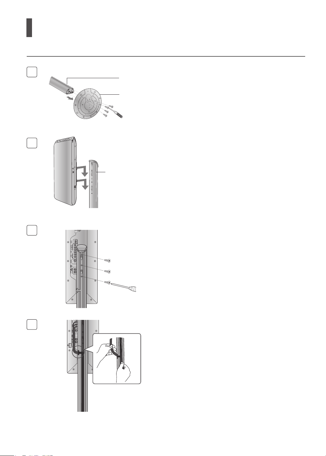
Installing the DVD player
1
1
2
STAND
STAND BASE
STAND
3
Mount the stand on the stand base and tighten
1
4 screws on the bottom side of the stand base.
Secure the main unit by aligning 2 protruding points
2
on the back of the main unit with the fixing holes on
the stand.
Tighten 3 screws in the middle of the stand.
3
Push the cable into the cable fixing hole in the
4
4
stand.
14 15
ENG
CONNECTIONS
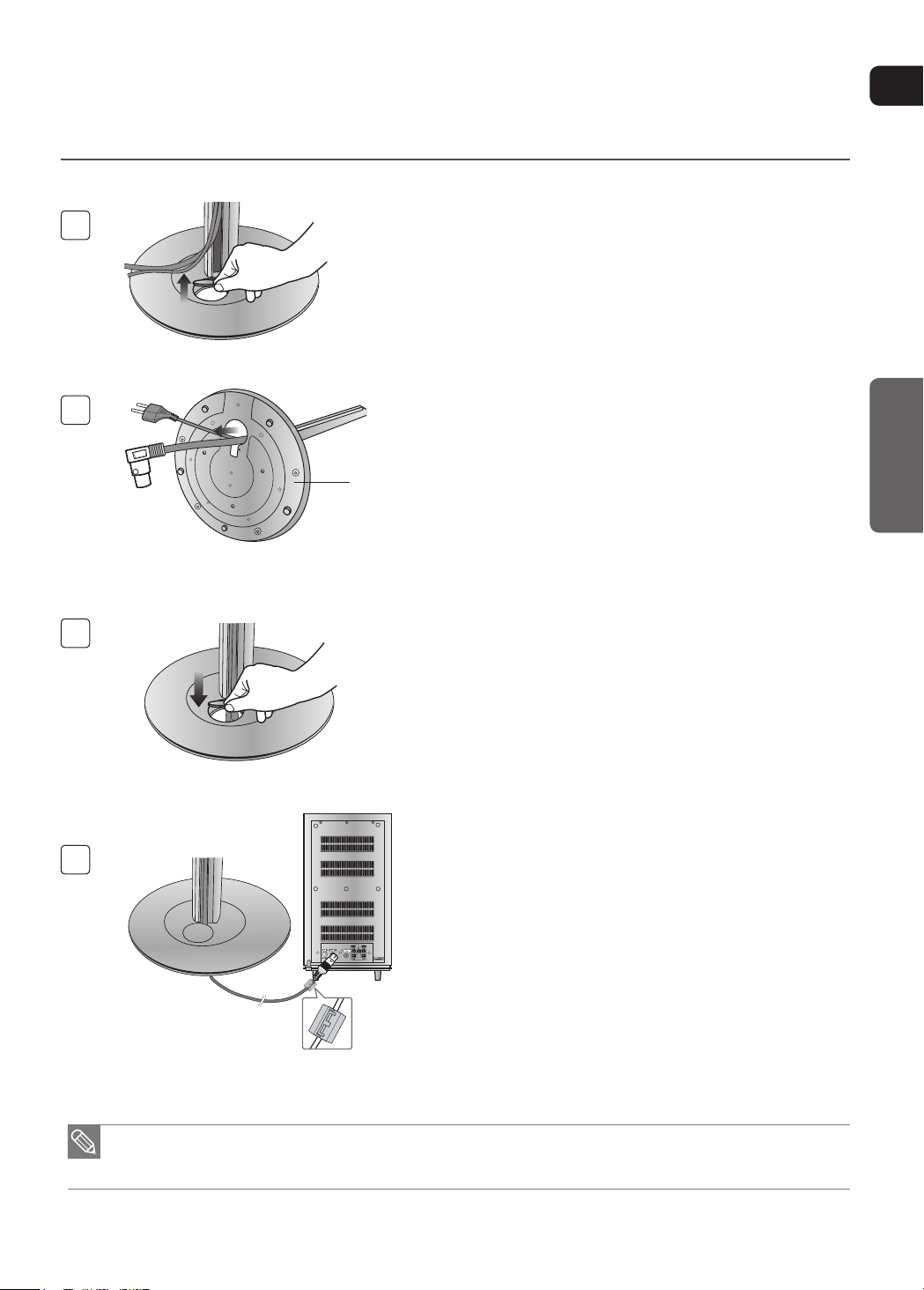
5
6
Round Table
Holder
7
Open the holder cover of the round board on the
5
bottom of the stand and pass the cables through the
holder.
Squeeze the cables into the groove on the holder of
6
the round board.
Close the holder cover.
7
Open a Toroidal Ferrite Core by pulling it upward.
8
8
For the stand packages, refer to page 9.
•
The Toroidal Ferrite Core is designed to reduce electromagnetic waves that may cause interference.
•
Wrap it around of the system connection cable so
it will be next to the DVD Player. Close it back by
pressing it all the way down until you hear a clicking
sound.
Connecting the Speakers
SRSL
C
L
SW
R
Before moving or installing the product, be sure to turn off the power and disconnect the power cord.
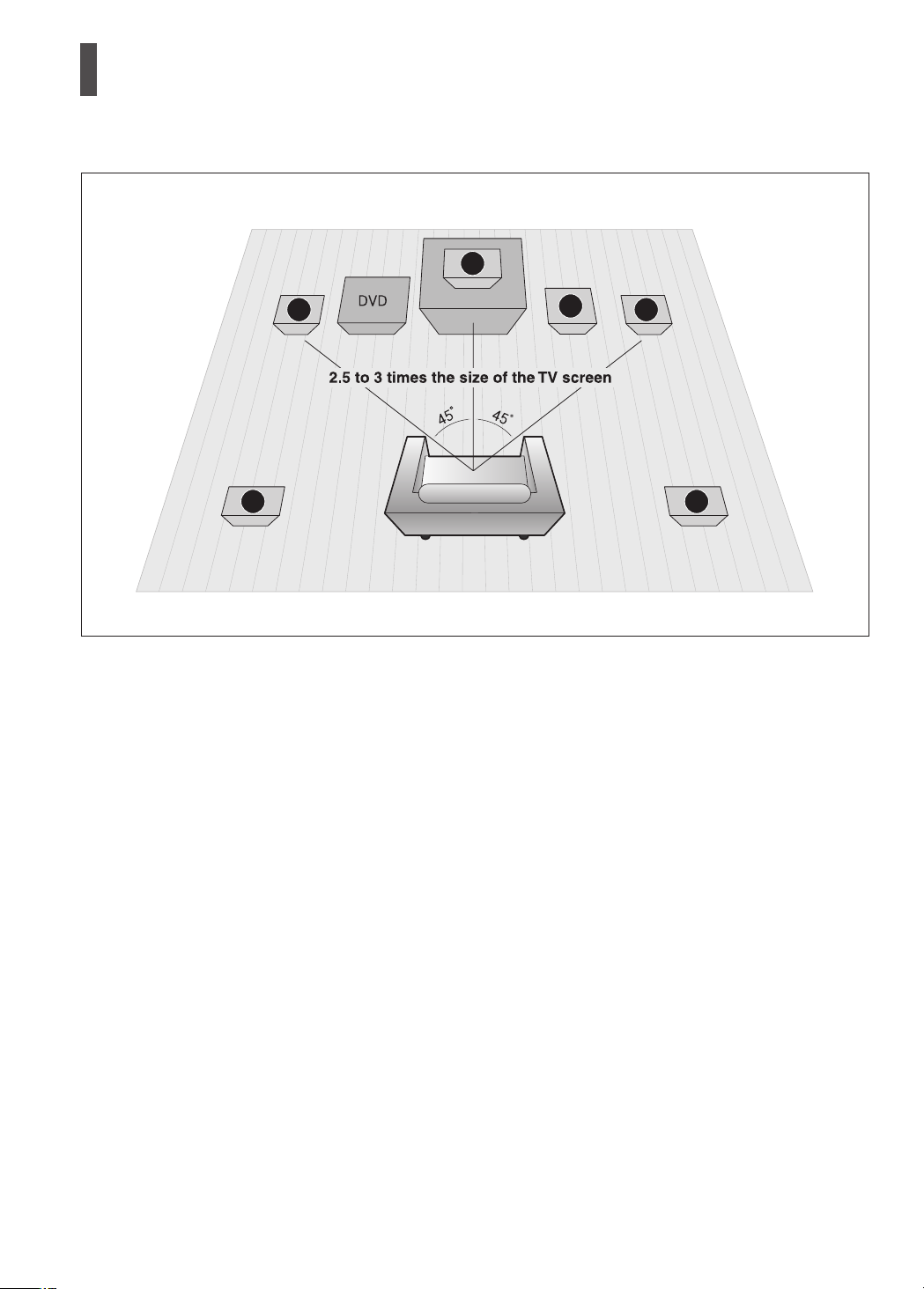
Position of the DVD Playerei
Place it on a stand or cabinet shelf, or under the TV
•
stand.
Front Speakers f
Place these speakers in front of your listening position,
•
facing inwards (about 45°) toward you.
•
Place the speakers so that their tweeters will be at the
same height as your ear.
•
Align the front face of the front speakers with the front
face of the center speaker or place them slightly in front
of the center speakers.
Center Speaker
It is best to install it at the same height as the front
•
speakers.
•
You can also install it directly over or under the TV.
Selecting the Listening Position
The listening position should be located about 2.5 to 3
•
times the distance of the TV's screen size away from the
TV. Example :
For 32" TVs 2~2.4m (6~8feet)
For 55" TVs 3.5~4m (11~13feet)
Rear Speakers hj
Place these speakers behind your listening position.
•
•
If there isn't enough room, place these speakers so they
face each other.
•
Place them about 60 to 90cm (2 to 3feet) above your
ear, facing slightly downward.
* Unlike the front and center speakers, the rear speakers
are used to handle mainly sound effects and sound will
not come from them all the time.
Subwoofer g
The position of the subwoofer is not so critical.
•
Place it anywhere you like.
16 17
ENG
CONNECTIONS
POWER
ON OFF
AUDIO IN
CROSS OVER
AUDIO IN
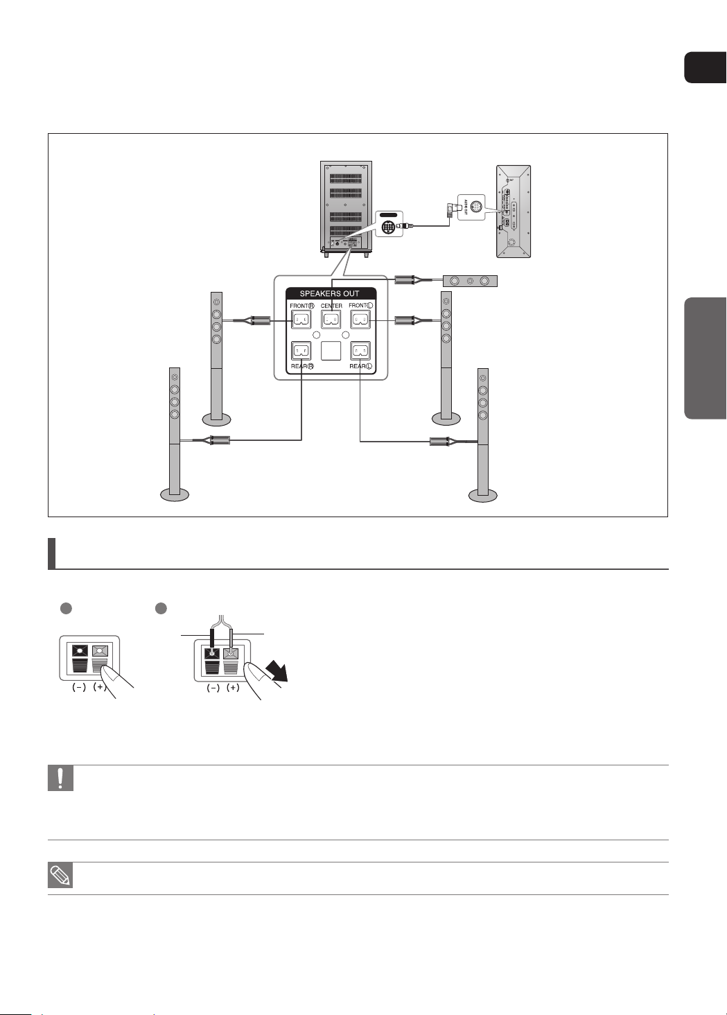
Rear of Subwoofer Rear of Main unit
Center Speaker
Front Speaker (L)Front Speaker (R)
Rear Speaker (R) Rear Speaker (L)
Connecting the Speakers
Press down the terminal tab on the back of the speaker.
1
2
Black Red
Do not let children play with or near the speakers. They could get hurt if a speaker falls.
•
When connecting the speaker wires to the speakers, make sure that the polarity (+/–) is correct.
•
Keep the speaker out of reach of children so as to prevent children from inserting their hands or alien substances into the
•
duct (hole) of the subwoofer speaker.
Do not hang the subwoofer on the wall through the duck(hole)
•
If you place a speaker near your TV set, screen color may be distorted because of the magnetic field generated by the
•
speaker. If this occurs, place the speaker away from your TV set.
1
Insert the black wire into the black terminal (–) and the
2
red wire into the red (+) terminal, and then release the
tab.
Connect the connecting plugs to the back of the Subwoofer.
3
Make sure the colors of the speaker terminals match the colors of the
connecting plugs.
POWER
ON OFF
AUDIO IN
CROSS OVER
AUDIO IN
Connecting the Speakers (Con’t)
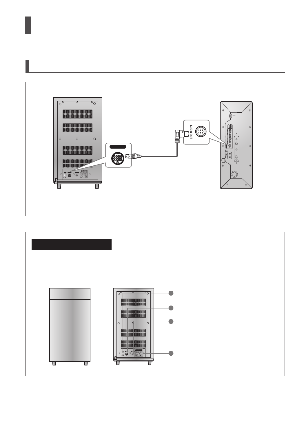
Connecting the Main Unit and Subwoofer
Rear of Subwoofer Rear of Main unit
Use the system cable to connect the AUDIO OUT port of the main unit to the AUDIO IN port of the subwoofer.
subwoofer functions
Subwoofer: With the built-in, dedicated 165W amplier, the subwoofer generates rich
bass sounds.
Crossover: The Crossover sets the cutoff frequency for the subwoofer.
Set the Crossover control for the best bass response in your room.
1
2
3
4
Power button
1
External Audio Input Connector
2
Crossover Controller
3
Speaker Output Terminals
4
18 19
ENG
CONNECTIONS
POWER
ONOFF
AUDIO IN
CROSS OVER
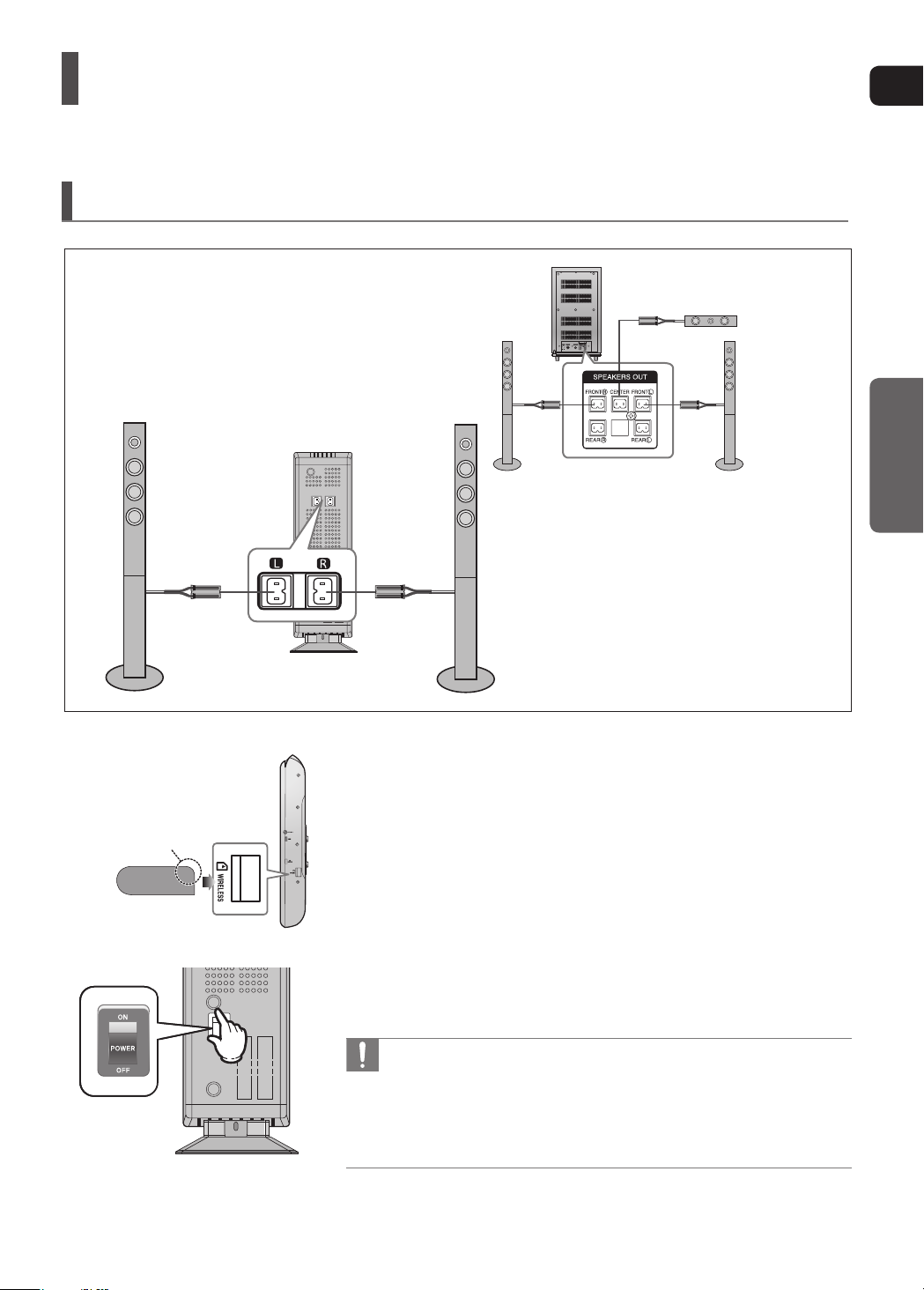
Connecting the Wireless Receiving Amplifier
To connect the rear speakers wirelessly, you have to purchase the wireless receiving module and TX card from your
Samsung retailer.
When you have Purchased the Wireless Receiving Module (SWA-3000)
Rear of Subwoofer
Center Speaker
Rear Speaker (L)
WIRELESS RECEIVER MODULE
Slanted side face up
TX card
Front Speaker (R)
Front Speaker (L)
Rear Speaker (R)
Connect the Front and Center speakers to the Subwoofer,
1
refering to pages 16~18.
With the DVD Player turned off, insert the TX card into the TX
2
Card Connection(WIRELESS) on the side of the main unit.
Hold the TX card so that the slanted side faces upward and insert the card into
the port.
The TX card enables communication between the main unit and the wireless
receiver.
Connect the left and right rear speakers to the wireless receiving
3
module.
Plug the power cord of the wireless receiving module in the wall
4
outlet and switch the power switch ‘ON’.
Do not insert a card other than the TX card dedicated for the product. The
•
product might be damaged or the card may not be removed easily.
Do not insert the TX card upside down or in the reverse direction.
•
Insert the TX card when the DVD Player is turned off. Inserting the card
•
when it is turned on may cause a problem.
If the TX Card is inserted, sound is not output from the Rear Speaker con-
•
nectors on the main unit.
Connecting the Wireless Receiving Amplier (Con’t)
Resetting the Wireless Receiving Module
Reset the system if a communication failure occurs, or if the Link indicator (blue LED) on the wireless receiver does not
light up and the "REAR CHECK" message blinks on the main unit's display.
Reset the system while the main unit and the wireless receiver module (SWA-3000) are in Power Standby mode.
1
With the main unit turned off, press and hold the remote
control's RESERVE button for 5 seconds.
The STANDBY LED on the front panel of the wireless
`
receiver module blinks.
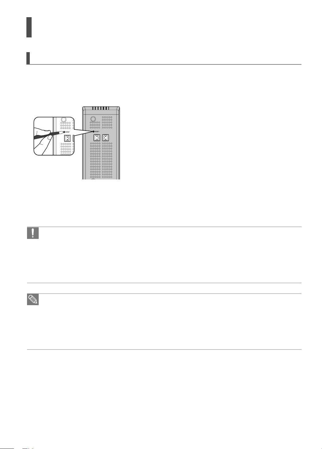
2 With the wireless receiver module turned on, use a ball point
pen or a toothpick to press the RESET button on the back of
the unit.
The STANDBY LED on the front panel of the wireless receiver
`
module blinks 2 Times.
3
Press and hold the Power button on the home theater
system for more than 1 second to turn it on.
The LINK LED of the wireless receiver module is lit and the
`
Reset is complete.
If Power Standby mode continues, repeat Steps 1 to 3 above.
`
When the wireless receiving module setting is complete, no audio signal is output from the Rear Speaker Output
•
Connector on the back of the main unit.
The wireless receiving antenna is built into the wireless receiver module. Keep the unit away from water and
•
moisture.
For optimal listening performance, make sure that the area around the wireless receiver module location is clear
•
of any obstructions.
Sound will be heard from the wireless rear speakers in DVD 5.1-CH or Dolby Pro Logic II mode only.
•
In 2-CH mode, no sound will be heard from the wireless rear speakers.
•
Place the wireless receiver module at the rear of the listening position. If the wireless receiver module is too
•
close to the main unit, some sound interruption may be heard due to interference.
If you use a device such as a microwave oven, wireless LAN Card, Bluetooth equipment, or any other device
•
that uses the same frequency (2.4GHz) near the system, some sound interruption may be heard due to
interference.
The transmission distance of radio wave is about 10m, but may vary depending on your operating environment.
•
If a steel-concrete wall or metallic wall is between the main unit and the wireless receiver module, the system
may not operate at all, because the radio wave cannot penetrate metal.
20 21
ENG
CONNECTIONS
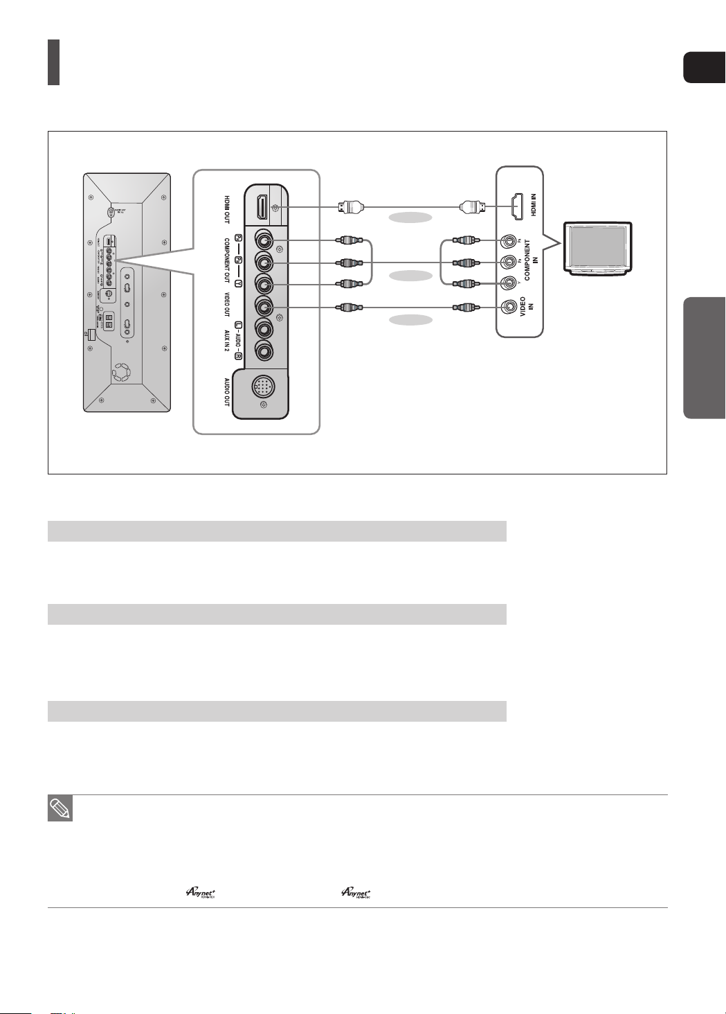
Connecting the Video Out to your TV
Choose one of the three methods for connecting to a TV.
METHOD 1
(supplied)
METHOD 2
METHOD 3
(supplied)
METHOD 1 : HDMI ....... (Best Quality)
Connect the HDMI cable from the HDMI OUT jack on the back of the main unit to the HDMI IN jack
on your TV.
METHOD 2 : Component Video .... (Better Quality)
If your television is equipped with Component Video inputs, connect a component video cable
(not supplied) from the Pr, Pb and Y jacks on the back panel of the main unit to the corresponding
jacks on your television.
METHOD 3 : Composite Video ....... (Good Quality)
Connect the supplied video cable from the VIDEO OUT jack on the back of the main unit to the
VIDEO IN jack on your TV.
This product operates in Interlace scan mode (576i) for component output.
•
After making the video connection, set the Video input source on your TV to match the corresponding
•
Video output (HDMI, Component or Composite) on your Home theater.
See your TV owner's manual for more information on how to select the TV's Video Input source.
If you use an HDMI cable to connect a Samsung TV to the main unit, you can operate the Home Theater using
•
the TV's remote control. This is only available with SAMSUNG TVs that support Anynet+(HDMI-CEC).
Please check the
•
logo. If your TV has an logo, then it supports Anynet+ function.
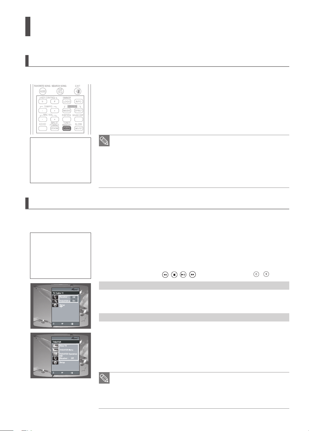
HDMI Function
View TV
THEATER
THEATER Menu
Move
Enter
Exit
Setup
Connected to Player
Off
On
View TV
THEATER
THEATER Menu
Resolution Selection
This function allows the user to select the screen resolution for HDMI output.
In Stop mode, press and hold the SD/HD (Standard Denition/High Denition)
button on the remote control.
Resolutions available for the HDMI output are 576p, 720p, 1080i and 1080p.
`
SD(Standard Denition) resolution is 576p(480p) and HD(High Denition)
`
resolution is 720p/1080i/1080p.
If the TV does not support the congured resolution, you will not be able
What is HDMI (High Denition
Multimedia Interface)?
This device transmits a DVD
video signal digitally without
the process of converting to
analog. You will get sharper
digital pictures when using
an HDMI connection.
•
to see the picture properly.
When a HDMI TV is connected, composite and component video signals are not output.
•
See your TV owner's manual for more information on how to select the TV's
•
Video Input source.
The Home Theatre is designed for qualitative playback DVD discs recorded in
•
PAL system. While useing NTSC discs in HD mode in some cases it's
possible picture size distortion which is not a defect
Using Anynet+(HDMI-CEC)
Anynet+ is a function that enables you to control other Samsung Devices with your Samsung TV's remote control, Anynet + can be used
by connecting this Home Theater to a SAMSUNG TV using an HDMI Cable. This is only available with SAMSUNG TVs that support Anynet+.
1
With Anynet+
You can operate this unit,
power on your TV, or
watch a movie by pressing
the Play button on your
Samsung TV's remote
control.
MOVE
ENTER
EXIT
MOVE
ENTER
EXIT
Connect the main unit of the Home Theater to a Samsung TV with an HDMI cable.
(See page 21)
2 Set the Anynet+ function on your TV.
(See the TV instruction manual for more information.)
You can operate the Home Theater by using the TV remote control.
`
(Available TV buttons : , , , , $, % and +,_ buttons, ~ button)
If you select the TV
Set the Anynet+(HDMI-CEC) to <On> on your TV.
<Receiver : On> : You can listen to audio through the Home Theater.
`
<Receiver : Off> : You can listen to audio through the TV.
`
If you select the THEATER
Select <THEATER to connector> and set the option of each items below.
<View TV> : If Anynet+(HDMI-CEC) set to on and you select View TV, the
`
Home Theater will automatically switched to DIGITAL IN.
<THEATER Menu> : You can access the Home Theater menu.
`
<THEATER Operation> : The Home Theater disc playback information will be displayed.
`
<Receiver : On> : You can listen to audio through the Home Theater.
`
<Receiver : Off> : You can listen to audio through the TV.
`
If you want to listen to TV sound through the home theater system, connect the optical
•
cable to the OPTICAL 1 port of the system.
If Anynet+ (HDMI-CEC) is on and you turn off the main unit, your TV will also
•
turn off.
Anynet+ (HDMI-CEC) will only work while in the DVD mode.
•
22 23
ENG
CONNECTIONS
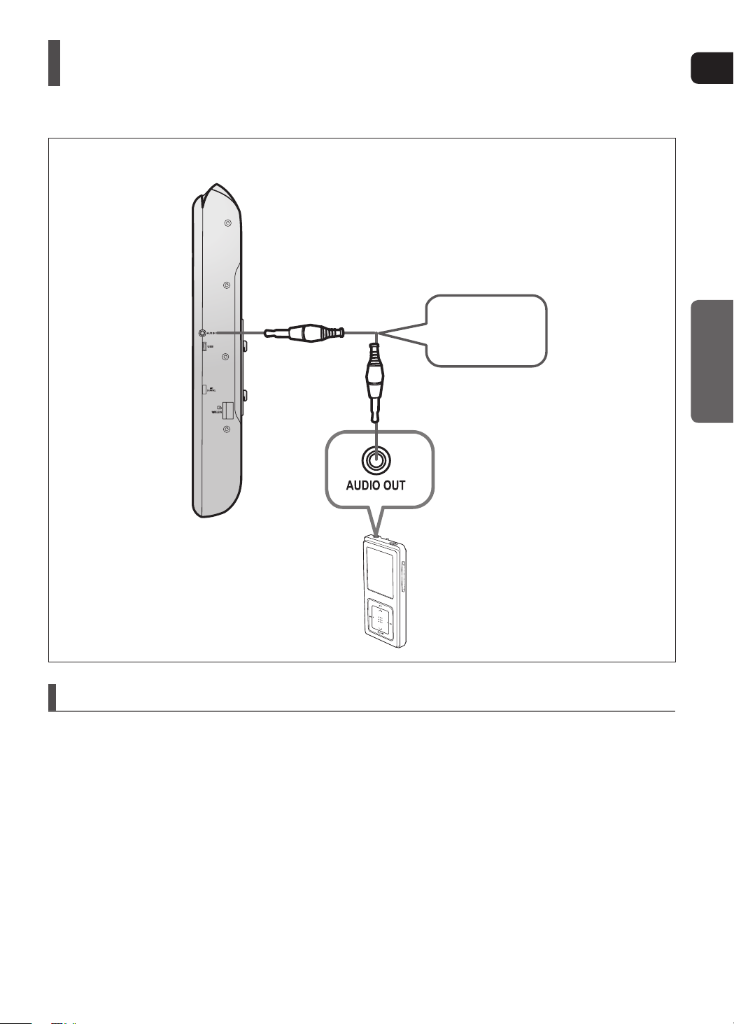
Connecting Audio from External Components
AUX1 : Side Panel
Audio Cable
(not supplied)
AUX1 : Connecting an External Component/MP3 player
Components such as an MP3 Player
1
Connect AUX IN 1 (Audio) on the Home Theater to the Audio Out of the external component/MP3 player.
2
Press the AUX button on the remote control to select <AUX1> input.
You can also use the FUNCTION button on the main unit.
•
The mode switches as follows : DVD ; D.IN 1
;
D.IN 2
;
AUX1
;
AUX2 ; USB ; FM
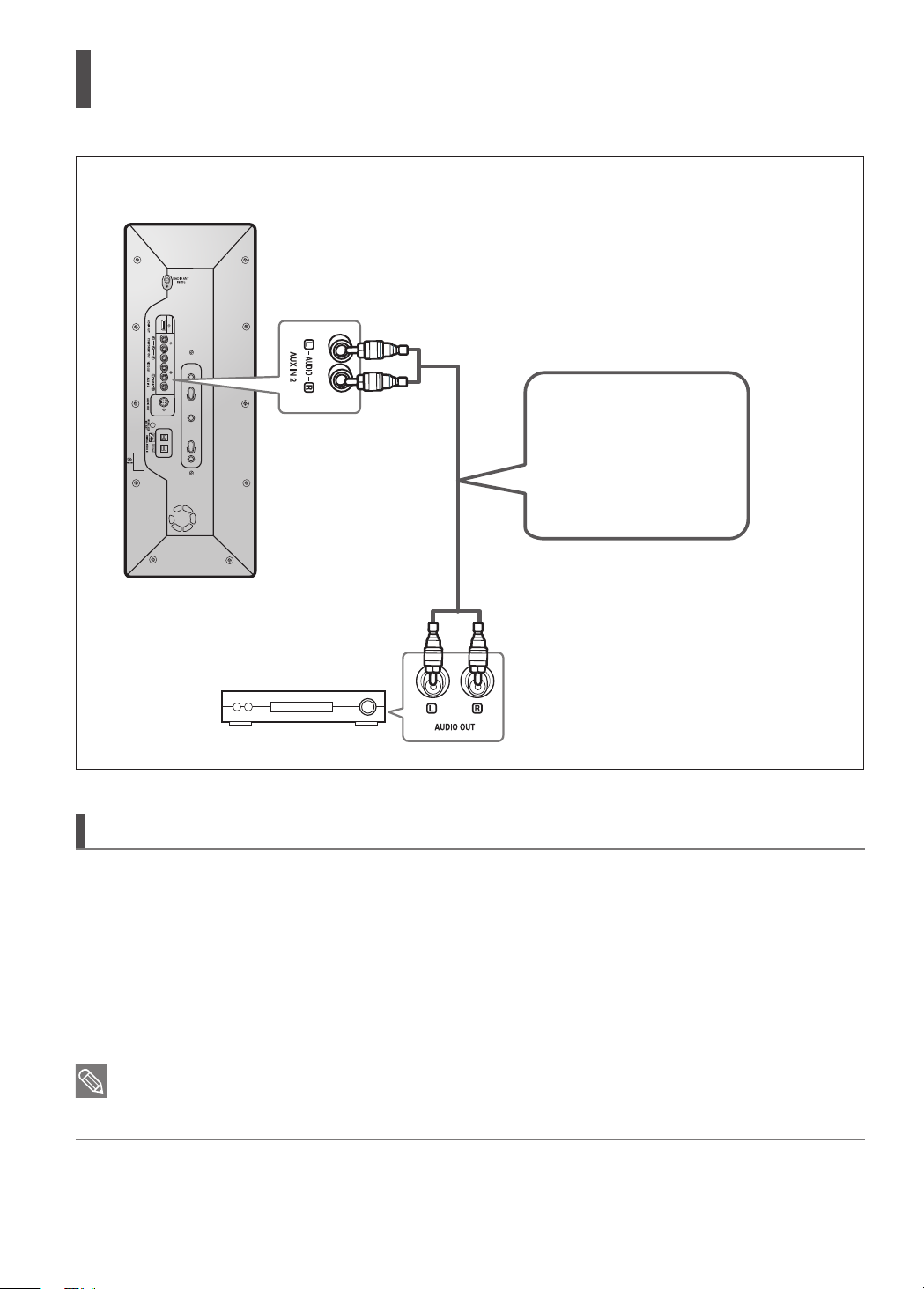
Connecting Audio from External Components (Con’t)
AUX2 : Rear Panel
Audio Cable
(not supplied)
If the external analog
component has only one
Audio Out, connect
either left or right.
AUX2 : Connecting an External Analog Component
Analog signal components such as a VCR.
1
Connect AUX IN 2 (Audio) on the Home Theater to Audio Out on the external analog component.
Be sure to match connector colors.
•
2
Press the AUX button on the remote control to select <AUX2> input.
You can also use the FUNCTION button on the main unit.
•
The mode switches as follows : DVD ; D.IN 1
You can connect the Video Output jack on your VCR to the TV, and connect the Audio Output jacks on the VCR
•
to this product.
24 25
;
D.IN 2 ; AUX1 ; AUX2 ; USB ; FM
ENG
CONNECTIONS
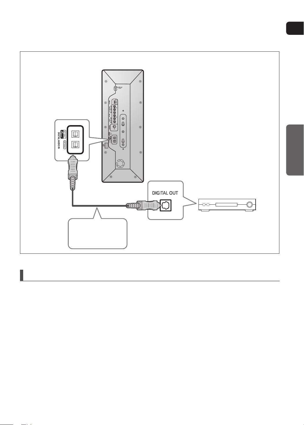
OPTICAL : Rear Panel
Optical Cable
(not supplied)
OPTICAL : Connecting an External Digital Component
Digital signal components such as a Set-Top Box.
1
Connect the Digital Input (OPTICAL 1 or 2) on the Home Theater to the Digital Output of the external digital component.
2
Press the AUX button on the remote control to select <D.IN 1>, <D.IN 2>
You can also use the FUNCTION button on the main unit.
•
The mode switches as follows
: DVD ; D.IN 1 ; D.IN 2 ;AUX 1 ; AUX 2 ; USB ; FM
 Loading...