

Page 1

DIGITAL HOME
THEATER SYSTEM
HT-DL200P
V I D E O
Function
Volume
Phones
V I D E O
COMPACT
DIGITAL AUDIO
COMPACT
DIGITAL VIDEO
Instruction Manual
SAMSUNG ELECTRONICS CANADA, INC.
Bureau-chef
7037 Financial Drive, Mississauga, Ontario, Canada L5N 6R3
TEL: 1-905-542-3535
www.samsungcanada.com
Centre de service
7037 Financial Drive, Mississauga, Ontario, Canada L5N 6R3
1-800-SAMSUNG (1-800-726-7864)
Page 2

GB GB
PrecautionsSafety W arnings
1
Ensure that the AC power supply in your house complies with the identification sticker located on the back of your player. Install your player
horizontally, on a suitable base (furniture), with enough space around it for ventilation (3~4inches). Make sure the ventilation slots are not
covered. Do not stack anything on top of the player. Do not place the player on amplifiers or other equipment which may become hot.
Before moving the player ensure the disc tray empty. This player is designed for continuous use. Switching off the DVD player to the stand-by
mode does not disconnect the electrical supply. In order to disconnect the player completely from the power supply, remove the main plug
from the wall outlet, especially when left unused for a long period of time.
Protect the player from moisture(i.e. vases) , and excess heat(e.g.fireplace) or
equipment creating strong magnetic or electric fields (i.e.speakers...).
Disconnect the power cable from the AC supply if the player malfunctions.
Your player is not intended for industrial use.
Use of this product is for personal use only.
Condensation may occur if your player or disc has been stored in a cold
atmosphere.
If transporting the player during the winter, wait approximately 2 hours until
the unit has reached room temperature before using.
During thunderstorms, disconnect AC main plug from the wall
outlet.
Voltage peaks due to lightning could damage the unit.
Do not expose the unit to direct sun radiation or other heat
sources.
This could lead to overheating and malfunction of the unit.
The battery used with this product contain chemicals that are
harmful to the environment.
Do not dispose of batteries in the general household trash.
2
CLASS 1 LASER PRODUCT
This Compact Disc player is classified as a CLASS 1
LASER product.
Use of controls, adjustments or performance of
procedures other than those specified herein may result
in hazardous radiation exposure.
CAUTION-INVISIBLE LASER RADIATION WHEN OPEN
AND INTERLOCKS DEFEATED, AVOID
EXPOSURE TO BEAM.
This symbol indicates that dangerous voltage which can cause electric shock is present inside
this unit.
This symbol alerts you to important operating and maintenance instructions accompanying
the unit.
WARNING: To reduce the risk of fire or electric shock, do not expose this appliance to rain or moisture.
CAUTION: TO PREVENT ELECTRIC SHOCK, MATCH WIDE BLADE OF PLUG TO WIDE SLOT, FULLY
INSERT.
CLASS 1 LASER PRODUCT
KLASSE 1 LASER PRODUKT
LUOKAN 1 LASER LAITE
KLASS 1 LASER APPARAT
PRODUCTO LASER CLASE 1
RISK OF ELECTRIC SHOCK.
DO NOT OPEN
CAUTION:
TO REDUCE THE RISK OF ELECTRIC
SHOCK, DO NOT REMOVE REAR COVER.
NO USER SERVICEABLE PARTS INSIDE.
REFER SERVICING TO QUALIFIED
SERVICE PERSONNEL.
CAUTION
olume
V
on
i
t
c
un
F
es
n
ho
P
O
E
D
I
V
V I D E O
Volume
Function
Phones
V I D E O
Volume
Function
Phones
V I D E O
Function
Volume
Phones
V I D E O
Volume
Function
Phones
Page 3

GB
4
GB
DVD (Digital Versatile Disc) offers fantastic audio and video, thanks to Dolby
Digital surround sound and MPEG-2 video compression technology. Now you can
enjoy these realistic effects in the home, as if you were in a movie theater or concert
hall.
V I D E O
DVD players and the discs are coded by region. These regional codes must match in
order for the disc to play. If the codes do not match, the disc will not play.
The Region Number for this player is given on the rear panel of the player.
(Your DVD player will only play DVDs that are labeled with identical region codes.)
1 6
~
3
Contents
Copy Protection
•
Many DVD discs are encoded with copy protection. Because of this, you should only connect your
DVD player directly to your TV, not to a VCR. Connecting to a VCR results in a distorted picture
from copy-protected DVD discs.
•
This product incorporates copyright protection technology that is protected by methods claims of certain
U.S. patents and other intellectual property rights owned by Macrovision Corporation and other rights
owners. Use of this copyright protection technology must be authorized by Macrovision Corporation, and
is intended for home and other limited viewing uses only unless otherwise authorized by Macrovision
Corporation. Reverse engineering or disassembly is prohibited.
Safety Warnings
Precautions
Description
Remote Control Unit
Connecting the Speakers
Connecting Video to TV
Connecting the FM and AM
(MW) Antennas
AUX Connections
P.SCAN
(Progressive Scan) Function
Before Using the DVD Player
DVD Playback
Forward/Reverse Searching
Slow Playback/Checking the Remaining Time
Repeat Playback
Using Disc Menu/Title
Program Playback
Selecting the Audio Language/Subtitle Language
Various DVD Functions
•
To enlarge an image
•
Selecting the desired Screen Angle
•
To move directly to a title, chapter, or time
MP3 Playback
System Setup
Setting up the Language Features
Controlling a TV with the Remote
Speaker Setup
Creating Realistic Sound Fields
Dolby Pro Logic II decoder
DSP
(Digital Signal Processor) Modes
Sleep Function
Listening to the Radio
Presetting stations
Troubleshooting
Cautions on Handling and Storing Discs
Disc Type and Protection
Specifications
1
2
5
7
9
10
11
12
13
14
15
17
18
19
20
21
23
24
24
24
24
25
27
29
30
31
34
35
37
38
39
40
41
43
44
45
•
LD, CDG, CD-I, CD-ROM and DVD-ROM cannot be played on this player.
If such discs are played, a "WRONG DISC FORMAT" message appears on the TV screen.
•
DVD discs purchased abroad may not play on this player.
If such discs are played, a "WRONG REGION CODE" message appears on the TV screen.
Do not use the following types of disc!
Page 4
GB GB
65
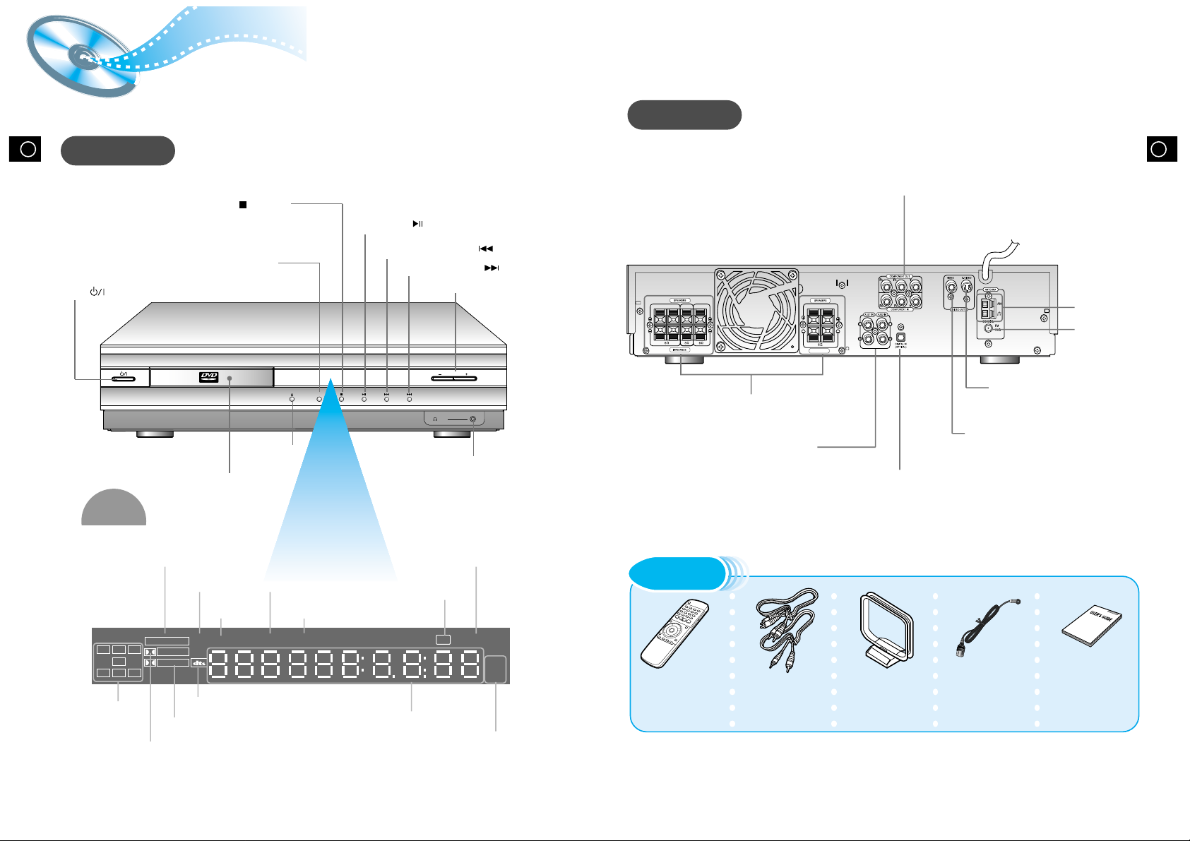
Description
Front Panel
Remote Control Video/Audio Cable User's Manual FM Antenna AM Antenna
Accessories
V I D E O
Function
Volume
Phones
Volume control
Play/Pause ( ) button
Stop ( ) button
Tuning Down & Skip ( ) buttons
Tuning Up & Skip ( ) buttons
Power ( ) button
Headphone Jack
TITLE
indicator
DTS Disc indicator
PRO LOGIC indicator
Display
PRO LOGIC
LINEAR PCM
DSP TITLE PBC
PRGM
ST TUNED
kH
Z
MH
Z
LCR
LS
LFE
SRS
D I G I T A L
STEREO indicator
DSP
indicator
PBC
indicator
RADIO
FREQUENCY
indicator
PROGRAM
indicator
System Status Display
SPEAKER
indicator
DOLBY DIGITAL indicator
TUNER indicator
Open/Close button
Disc Tray
Function button
LINEAR PCM
indicator
Rear Panel
R-REAR-L WOOFER CENTER
R-FRONT-L
IMPEDANCE
5.1 Channel Speaker
Output Terminals
COMPONENT VIDEO
OUTPUT/INPUT jacks
Connect a TV with component video
input jacks to these jacks.
External Digital Component Input
Connectors
Use these for connections to external
equipment capable of digital output.
Video Output Connector
Connect the TV's video input jacks (VIDEO
IN) to the VIDEO OUT connector.
S-Video Output Connector
If the TV is equipped with an S-Video
input connector (S-VIDEO IN), connect it
to the player's S-Video output jack.
AM Antenna
Connector
FM Antenna
Connector
External Audio Component
Input Connector
Page 5
GB GB
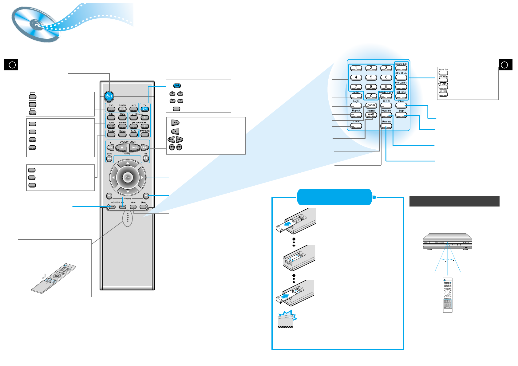
Remote Control Unit
7 8
DVD POWER button
DSP/DPL II Mode button
DSP/DPL II Effect button
TV Power button
TV Channel Selection button
TV Volume Control button
TV/VIDEO button
Title
Menu
Subtitle
Audio
MO/ST
Display
Return
Go To
Channel
Volume
TV/VIDEO
TV
DVD button
TUNER button
AUX button
Title button
Menu button
Subtitle button
Audio
MO/ST(mono/stereo) button
Display button
Return button
Go To button
DVD
TUNER
Band
AUX
Mute button
Volume Control buttons
Speaker output volume control
Play/Pause button
Stop button
Tuning Preset/CD Skip button
Tuning Up/Down/CD Search button
Sleep button
Direction/Enter button
V I D E O
Function
Volume
Phones
30
30
7~10m
Remove the battery cover on
the back of the remote by
pressing down and sliding the
cover in the direction of the
arrow.
Insert Remote Batteries
Range of Operation of the Remote Control
1
Insert two 1.5V AAA batteries,
paying attention to the correct
polarities (+ and –).
2
Replace the battery cover.
3
The remote control can be used up to
approximately 23 feet/7 meters in a straight line.
It can also be operated at a horizontal angle of
up to 30° from the remote control sensor.
Follow these precautions to avoid leaking or cracking cells:
•
Place batteries in the remote control so they match the
polarity:(+) to (+)and (–)to (–).
•
Use the correct type of batteries.Batteries that look similar
may differ in voltage.
•
Always replace both batteries at the same time.
•
Do not expose batteries to heat or flame.
CAUTION
To open the remote control
cover, push the top of the
cover, then slide downward.
Clear button
Step button
Program button
Remain button
Sound Edit button
SPK Mode button
Pro Logic II button
Test Tone button
Slow button
Angle button
Repeat button
P.Scan button
Repeat A↔B button
Zoom button
Setup/P.Scan Adjust button
D.R.C button
Number(0~9) buttons
Page 6

GB GB
9
Connecting the Speakers Connecting
Video to TV
• Connect the satellite speakers, center speaker, and
subwoofer to the terminals on the rear panel using speaker
cords supplied.
• Insert the end of the speaker cord into the terminal.
Match the polarity (colors): Red (+) to red (+) and black (–)
to black (–).
Subwoofer
Left front
speaker
Left rear
speaker
Right rear
speaker
Right front
speaker
Center
speaker
Press and hold the terminal tab.
1
Insert the speaker cord.
2
Release your finger.
3
1 2 3
•for in-depth information about adjusting the delay time,
see “Speaker Settings” on page 32.
10
Right rear speaker
Right front speaker
Left front speaker
Left rear speaker
Center speaker
Subwoofer
R-REAR-L WOOFER CENTER
R-FRONT-L
IMPEDANCE
Composite Video (Good Quality)
Connect the supplied video cable from the VIDEO OUT jack on the back panel of the
system to the VIDEO IN jack on your television.
S-Video (Better Quality)
If you television is equipped with an S-Video input, connect an S-Video cable (not supplied)
from the S-VIDEO OUT jack on the back panel of the system to the S-VIDEO IN jack on
your television.
Component Video (Best Quality)
If your television is equipped with Component Video inputs, connect a component video
cable (not supplied) from the Pr, Pb and Y jacks on the back panel of the system to the
corresponding jacks on your television.
R-REAR-L WOOFER CENTER
R-FRONT-L
IMPEDANCE
Composite
Video
Component
Video
S-Video
TV
•
When the Progressive scan mode is selected, the VIDEO and S-VIDEO outputs do not feed
any signals.
Page 7

GB GB
FM antenna connection
1. Connect the FM antenna supplied to the FM 75Ω
COAXIAL terminal.
2. Slowly move the antenna wire around until you
find a location where reception is good, then
fasten it to a wall or other rigid surface.
•
If reception is poor, connect an outdoor antenna.
Before attaching a 75Ω coaxial cable (with a standard
type connector), disconnect the supplied FM antenna.
AM(MW) antenna connection
1. Connect the AM loop antenna supplied
to the AM and terminals.
2. If reception is poor, connect an outdoor
single vinyl-covered wire to the AM
terminal. (Keep the AM loop antenna
connected).
12
Connecting the FM and AM
(
MW/LW
)
Antennas
11
A cooling fan is mounted on the rear panel of the center unit to
prevent abnormal temperature inside the center unit, thus assuring
normal operation. The cooling fan automatically starts rotating to
supply external cool air to the inside of the center unit when the
internal temperature exceeds the specified limit.
For safety, observe the following carefully.
• Make sure there is good ventilation around the center unit. Poor
ventilation could overheat and damage the canter unit.
• DO NOT block the cooling fan and the ventilation openings or
holes. (If they are blocked by a newspaper or cloth, etc., the heat
may not be able to escape.)
(About the cooling fan)
AUX Connections
Snap the tabs on the loop into the
slots of the base to assemble the
AM loop antenna.
Cooling fan (See “About Cooling Fan” below.)
R-REAR-L WOOFER CENTER
R-FRONT-L
IMPEDANCE
ANTENNA
123
R-FRONT-L
IMPEDANCE
LR
DIGITAL OUT
External Digital
Components
External Analog
Components
Audio Cable (Red/White)
For connection to external
equipment with digital output.
Example: CD recorders, MD (Mini Disc) D/A
converters or other components equipped
with digital output jacks
Connect to external equipment with
analog output.
Example: Video, TV, LDP, etc.
•
Always connect the video and
audio connection cables to the
equivalent colored jack.
Press the AUX button and select AUX1 IN, AUX2 IN.
Making Analog Input Selection
Press the Function button and select AUX1 IN, AUX2 IN.
Remote Control
Main Unit
If the external analog
component has only one
output jack, you may
connect either L or R.
Optical Cable
Video Cable
If FM reception is poor,
connect outdoor FM antenna
(not supplied).
FM Antenna (supplied)
AM Loop Antenna
(supplied)
If AM reception is
poor, connect an
outdoor AM
antenna(not
supplied).
Page 8

GB GB
•
The “WAIT” message that appears on the display for about seven to eight seconds when
turning on the power or selecting a DVD function indicates a stabilization period for
optimizing the condition of your DVD player. While the message is being displayed, other
buttons remain inactive.
•
When the power is not turned on, press down the Stop ( ) button on the main unit for
over 5 seconds.
The product will be initialized to its optimum state.
•
Certain operational features such as the Speaker mode, Test tone, Volume, etc.
will not be displayed on the TV screen.
•
If your TV model is not SAMSUNG, refer to “Remote Control Unit Setup” on page 30.
Before Using the DVD Player
14
Your DVD player is capable of playing DVD, VCD, and CD discs.
User instructions may vary depending on the type of disc. Read the instructions
carefully before use.
TV
TV/VIDEO
DVD
Prepa-
rations
before
use
Turn on the power
to your DVD player
and TV.
1
Select a video mode by
pressing the TV/VIDEO
button.
2
Press the DVD button
to select the DVD input
function.
3
TV Broadcast System
• This device is designed to work with the NTSC video format.
• For normal playback, the video format a DVD disc is recorded in must
coincide with your TV's video format.
13
Connecting your System to the Power Supply
The AC plug must be plugged into an appropriate socket.
Before plugging your system into an AC outlet, you must check the voltage.
1. Plug the AC Cord on the rear of the system into an appropriate outlet.
2. Press the On/Standby button to switch your DVD Player system on.
Supports the Progressive scan system, as well as the conventional (current) Interlace scan system.
*To enjoy the progressive video picture, you must connect the unit to a television or monitor that
supports the progressive video input.
P.SCAN(Progressive Scan) Function
While the player is in the stop mode, hold the P.SCAN
button down for longer than 1 second.
•
The selection switches back and forth between "P.SCAN" and "I.SCAN"
each time the button is held down for a minimum of 1 second.
•
The previous mode is indicated in the display first, followed by the
selected mode in about a second.
Press the Setup/P.Adj button. (Play mode only)
•
Each time the Setup/P.Adj button is pressed, the following appears on the TV screen:
In interlaced-scan video, a frame consists of two
interlaced fields (odd and even), where each field
contains every other horizontal line in the frame.
The old field of alternating lines is displayed first, and
then the even field is displayed to fill in the alternating
gaps left by the odd field to form a single frame.
One frame, displayed every 1/30th of a second, contains
two interfaced fields, thus a total of 60 fields are
displayed every 1/60th of a second each.
The interlaced scanning method is intended for capturing
a still object.
Interlaced Scan (1 FRAME = 2 FIELDS)
The progressive scanning method scans one full frame of
video consecutively down the screen, line by line.
As opposed to the interlaced scanning process by which a
video image is drawn in a series of passes, you get an
entire image drawn at one time.
The progressive scanning method is desirable for dealing
with moving objects. A camera that has the ability to
capture moving objects is called a "full frame shutter
camera".
Progressive Scan (FULL FRAME)
What is Progressive (or Non-Interlaced) Scanning?
•
This function only works with TV's equipped with component video inputs (Y, P
r
, Pb).
•
Depending on the brand and model of your TV, this function may not work.
P.Scan Adj (Progressive Scan Adjusting)
This function allows you to optimize the picture quality when it becomes poor due to screen distortion or
discs containing erroneous data.
Page 9

GB
16
DVD Playback
15
GB
Press the Display button on the remote.
Depending on the disc, the initial disc
information screen may look different
from disc to disc.
If the player is left for more than 3 minutes
in pause mode, it will stop.
The On-Screen Display disappears.
Using the On-Screen Display
Display
Display
Display
Display
V I D E O
1/2 1/8 00:00:00
TC
V I D E O
ENG ENG OFF1/3 1/1
DVD indicator
TITLE indicator
TITLE ELAPSED
indicator
CHAPTER indicator
ANGLE indicator
REPEAT indicator
DISC TYPE indicator
AUDIO LANGUAGE
indicator
SUBTITLE LANGUAGE
indicator
Pausing Playback
Press the Play/Pause ( ) button during
playback.
•
To resume, press the Play/Pause ( )
button again.
Stopping Playback
Press the Stop ( ) button during playback.
•
During playback, when the Stop ( )button is pressed,
the position is stored in the memory, and STOP is
shown on the display.
When the Play/Pause ( ) button or Return button is
pressed subsequently , playback resumes from the
position at which it was stopped.
•
If the Stop ( ) button is pressed a second time, the
‘resume play’ memory function is canceled, and
STOP is shown on the display. When the Play/Pause
( )button is pressed, playback starts from the
beginning.
Turning the sound off temporarily?
What is a Title?
What is a Chapter?
Press the Mute button during playback.
•
This operation may be useful when you need
to greet guests or answer the telephone.
A movie contained in a
DVD disc.
Each Title on a DVD
disc is divided into
several smaller sections
called "chapters".
Mute
•
The button is located on the Front Panel
of the player (not on the remote).
Press the Open/Close( ) button
to open the disc tray.
1
•
Place a disc gently into the tray with the
disc’s label facing up.
Insert a disc.
2
V I D E O
•
Playback starts automatically.
Press the Open/Close( ) button
again to close the disc tray.
3
Page 10

Slow Playback/Checking the Remaining Time
18
GB
Forward/Reverse Searching
17
GB
Playing Slowly
Multi-Speed Playback
SLOW 1/2
SLOW 1/4
PLAY
X 2
X 4
X 8
PLAY
X 2
X 4
X 8
PLAY
Each time the button is pressed
Each time the button is pressed
Skipping through a Chapter
SEARCH
SEARCH
•
Each time the button is pressed during playback, it moves to the next
or previous chapter and plays it.
Each time the Slow button is pressed
•
For checking the total and remaining time of a
title or chapter being played.
The slow playback speed changes
and the selections (1/2X, 1/4X, 1/8X,
1/16X and normal play) are repeated.
Checking the Remaining Time
REMAIN TIME : CHAPTER
REMAIN TIME : TITLE
CHAPTER TIME
TITLE TIME
REMAIN TIME : DISC
REMAIN TIME : TRACK
DISC TIME
TRACK TIME
Playing Frame by Frame
•
The picture moves forward one frame each time the button is pressed.
Step
Each time the Remain button is pressed
Slow
Remain
Press the and button.
Press the Slow button.
Press the Remain button.
Press the and button.
Press the Step button.
During playback, you can search quickly through a chapter or track for a specific scene
or tune.
No sound is heard during
high-speed playback, slow
playback, and step motion.
▲
▲
▲
▲
▲
▲
▲
▲
▲
▲
▲
▲
Page 11

Using Disc Menu/Title
20
GB
Repeat Playback
19
GB
Playing Repeatedly
Each time the Repeat button is pressed
Repeat playback allows you to repeat a chapter, title, or track.
A↔B Repeat Playback
Press the Repeat A↔B button again.
1
2
Repeat
A B
Repeat
Title
Press the Repeat button.
To Select the Disc Menu
Press the Menu button during
playback.
1
Use the Up/Down (▲ / ▼ ) or
Left/Right( / ) button to
access the different features.
Press the Enter button.
2
•
The selected item will play.
•
The Menu Screen appears.
•
When playing VCD version
2.0, you can operate it using
PBC On/Off function.
3
Menu
You can use the menus for the audio language,
subtitle language, profile, etc. DVD menu contents
differ from disc to disc.
For DVDs containing multiple titles, you can
view the title of each movie.
Depending on the disc, this function may either
not work at all, or may work differently.
Using the Title Menu
•
Repeat playback operation is not possible with version 2.0 VCD discs if PBC is turned on.
To operate this feature, press the MENU button, and then select "PBC OFF".
Press the Repeat A↔B button at the
beginning (A) of the segment you want to
review.
Press the Repeat A
↔B button again at
the end (B) of the segment you want to
review.
•
The segment will begin repeating.
To return to normal playback
▲
▲
Page 12

GB
22
Program Playback
21
GB
To Program Tracks in a particular order
To Leave the Programming Mode
Press the Program button.
1
Press the Enter button, then
use the Number buttons to
select the desired title.
23
•
You can also use the Left/Right
( / / ▲ / ▼ ) button.
Press the Enter button, then use
the Number buttons to select the
desired chapter.
Press the Enter button.
4
At this time, you can continue
programming if you want to.
5
•
When programming more than
10 tracks, select and
then press the Enter button.
The program selection screen
where you can program up to
10 additional tracks appears.
•
The selected track number is
programmed and the cursor
moves to the next number.
•
Press the Stop ( ) button twice during playback.
•
Press the Stop ( ) button once when in the Stop mode.
•
Press the Open/Close ( ) button on the main unit.
The disc tray will open and then close.
The program will then be deleted.
To Playback the
Tracks in
Programmed Order
Press the Play/Pause
( ) button.
Press either the Program or Stop ( ) button.
To Change the Program
Press the Up/Down ( ▲ / ▼ )
button to select the track
number to be changed.
123
•
The cursor moves to the next
number when the Enter button
is pressed again.
Press the Enter button.
4
Repeat steps 1-4 above to
change the program.
5
•
The cursor moves to the
number below.
You can program or change
particular tracks for VCD or CD
discs in the same manner.
•
You can also use the Left/Right
( / ) button.
•
You can also use the Left/Right
( / / ▲ / ▼ )
button.
NEXT
To delete the entire Program
When you have entered a
wrong number
Clear
Press the Clear button.
•
When you want to delete a selection during
programming, select the track (or chapter, or title) to be
deleted and then press the Clear button.
Program
Use this function to program chapters or tracks in a particular order.
Press the Enter button to
select the title or chapter to be
changed.
Press the Clear button and
then press the Number
buttons.
▲
▲
▲
▲
▲
▲
PROGRAM MENU SELECT : ENTER
TITLE CHAPT
1
2
3
4
5
PREVIOUS NEXT
PLAY : FINISH : PROGRAM
TITLE CHAPT
6
7
8
9
10
PROGRAM MENU SELECT : ENTER
TITLE CHAPT
1 1 2
2
3
4
5
PREVIOUS NEXT
PLAY :
TITLE CHAPT
6
7
8
9
10
FINISH : PROGRAM
PROGRAM MENU SELECT : ENTER
TITLE CHAPT
1
1
2
3
4
5
PREVIOUS NEXT
PLAY :
TITLE CHAPT
6
7
8
9
10
FINISH : PROGRAM
PROGRAM MENU SELECT : ENTER
TITLE CHAPT
1
1
1
2
1
3
2
4
2
5
PREVIOUS NEXT
PLAY :
2
2
7
3
4
FINISH : PROGRAM
TITLE CHAPT
6
4
6
7
3
8
5
9
1
10
PROGRAM MENU SELECT : ENTER
TITLE CHAPT
1
2
1
2
3
4
5
PREVIOUS NEXT
PLAY :
1
2
4
5
2
TITLE CHAPT
6
7
8
9
10
FINISH : PROGRAM
Page 13

GB GB
•
Depending on the disc, DTS or DIGITAL PRO LOGIC can be
selected.
2423
To enlarge an image
•
Images can be enlarged 2x and 4x.
•
During DVD playback, press the Zoom button
to zoom in 2X/4X/normal, in that order.
•
Press
/ / ▲ / ▼ to move the enlarged
portion you want to watch.
•
This function only works with discs on which multiple angles have been recorded.
•
During playback, press the Angle button to select the desired angle in 1/3, 2/3, 3/3,
normal, in that order.
Selecting the desired Screen Angle
Various DVD Functions
Selecting the Audio Language/Subtitle Language
Selecting the Audio Language
V I D E O
OFF 1/1
ENGENG
SPA
FRE
1/3
2/3
3/3
•
Depending on the number of languages recorded on a DVD disc, a
different audio language (ENGLISH, SPANISH, FRENCH, etc.) is
selected each time the button is pressed.
Selecting the Subtitle Language
V I D E O
OFF1/1 1/1
SPA
ENG
FRE
OFF
ENG
1/3
2/3
3/3
•
Depending on the number of languages recorded on a DVD disc, a
different subtitle language (ENGLISH, SPANISH, FRENCH etc.) is
selected each time the button is pressed.
•
To make the subtitles disappear, select "OFF".
2
Zoom
Angle
Audio
MO/ST
Subtitle
Press the Zoom button.
Press the Angle button.
Press the Audio button.
Press the Subtitle button.
•
If the word INVALID appears on the TV screen while buttons are being
operated, that operation is not possible with that particular disc.
•
Depending on the disc, the audio or subtitle language function may not work.
To move directly to a title, chapter, or time
•
Each time the buttons are pressed the
desired scene is located and then played.
•
Depending on the disc, the Title function
may not work.
•
Each time the button is pressed, it repeats as shown below.
Press the Go To button.
1
Press Number(0~9) buttons or the
Left/Right ( / ) button.
2
Go T o
▲
▲
•
Only 2X zoom
operation is
possible during
VCD playback.
▲
▲
OFF 1/3
2/3
3/3
V I D E O
TITLE
00:00:00
C
1/8
T
1/2
T
V I D E O
CHAPTER
1/2
00:00:00
C
1/8
V I D E O
TIME
T
1/2
C
1/8
00:00:00
::
Page 14

GB
MP3 Playback
25
GB
26
This system has a built-in MP3 decoder.
You can play back MP3 tracks (files)recorded on CD-Rs, CD-RWs, and CD-ROMs.
•
It is recommended you turn on your
TV when playing back an MP3 disc.
Starting Playback
Press the Open/Close( ) button
to load a disc.
1
•
After detecting the disc, playback starts.
•
The on-screen bar and the contents
recorded on the MP3 disc will be shown
on the TV if it is turned on.
Press the Play/Pause( ) button.
2
To stop during playback
Press the Stop ( ) button.
Turn on your TV when playing back an MP3 disc.
Operations Using the On-Screen Display
When the loaded MP3 disc is recognized, the following
on-screen display appears on the TV screen.
(The contents of this on-screen display vary according to
the disc — the way MP3 tracks were recorded on the
disc.)
Button To do
ENTER, Start playback or go into a directory.
▲ / ▼
Select a track or directory.
On an MP3 disc, Repeat A↔B cannot be used.
You can enjoy only repeat play.
Repeating Playback
•
Each time you press the button, repeat mode
changes as follows:
Press the REPEAT button.
The indication corresponding to the selected mode
appears on the TV screen.
REPEAT:RANDOM
:
All tracks recorded on the disc will be played once in random order.
REPEAT:ONE
: Current track will be repeated.
REPEAT:DIR
: Tracks in the current directory will be repeated.
REPEAT:DISC
: All tracks on the disc will be repeated.
REPEAT OFF
: Repeat play is canceled.(Normal play is resumed.)
MP3 is an abbreviation of Motion Picture Experts Group
(or MPEG) Audio Layer 3. MP3 is simply a file format
with a data compression ratio of 1:10 (128 Kbps*).
That means,by using MP3 format, one CD-R or CD-RW
can contain 10 times as much data volume as a regular
CD can.
*Bit rate is the average number of bits that one second
of audio data will consume. The measuring unit used is
Kbps (1000 bits per second).
To obtain better audio quality, choose a higher bit rate.
The most popular bit rate for encoding (recording)is
128 Kbps.
What is MP3?
•This system can only read MP3 files that are recorded in
the format that is compliant with ISO 9660 Level 1 or
Level 2.
•The system can read or play MP3 files only with the
extension code —“.mp3 ”.
•ID3*tags cannot be shown on the display.
*An MP3 file can contain file information called “ID3 Tag ”
where its album name, performer, track title, etc. are
recorded.
MP3 File Compatibility
•
Your DVD player can also play CD-R and CDRW discs recorded in digital audio format.
When recording your own CD-R or CD-RW
discs, make sure that the recording session is
properly terminated, or they will not be
playable. (Depending on disc properties and
recording quality, some CD-R/RWs may not be
playable.)
•
CD-RW has a lower reflection rate than CD-R
media and consequently it will take a longer to
read CD-R discs.
•
CD-RW discs recorded at high speed tend to
be difficult for the DVD player to read. If the
recording speed for the CD-RW disc is not
predetermined, write it at low speed.
CD-R/RW playback compatibility
Repeat
Page 15

GB GB
28
4:3 LB
OFF
RATING LEVEL
BITSTREAM
OUTPUT
DIGITAL
TV SCREEN
: Move Setup : Exit
LANGUAGES SYSTEM
Select when you want to watch a 16:9 screen ratio DVD movie on a TV with a 4:3 ratio screen.
You can see the full 16:9 picture, but black bars will appear at the
top and bottom of the screen.
You can only view the central portion of the 16:9 screen.
You can view in widescreen, but the top and bottom of the picture
will be cut off.
•
If the movie is recorded in 4:3 ratio, you cannot view the full 16:9 picture with the above
functions.
4:3PS
4:3LB
16:9
TV SCREEN(TV SCREEN RATIO)
The Rating Level function works in conjunction with DVDs which have been assigned
a rating, to help control the type of DVD that your family watches.
1. Select RATING LEVEL, then press the
Enter button.
4:3 LB
BITSTREAM
OUTPUT
DIGITAL
TV SCREEN
RATING LEVEL
: Move Setup : Exit
LANGUAGES SYSTEM
2. Use the number(0~9) buttons to input
a 4-digit password.
•
The player’s password is set to "7890" by
default.
OUTPUT
DIGITAL
TV SCREEN
RATING LEVEL
: Move Setup : Exit
LANGUAGES SYSTEM
4:3 LB
3. Use the Up/Down (▲ / ▼ ) button to select either RATING LEVEL or
NEW PASSWORD, and then press the Enter button.
•
There are up to 8 rating levels on a disc.
•
If LEVEL 6 is selected, a disc which contains rating LEVEL 7 and above cannot
be played.
•
If you select NEW PASSWORD, the screen changes and enables you to enter
the new password.
RATING LEVEL
While the player is in the stop
mode, hold the Stop ( ) button
down on the main unit for more than
5 seconds.
•
"INITIAL" appears on the display and
all default settings will return to
Factory Preset.
•
Press the Power button.
When the rating level
password has been forgotten
You can use the DVD player's Setup function to select the TV screen ratio,
rating limit, or digital output mode.
27
System Setup
Press the Up/Down ( ▲ / ▼ ) button
to select the
desired sub-item
and then press the Enter
button.
45
From the stop mode, press
the Setup/P.Adj button.
1
Press the Left/Right ( / )
button to select the system.
Press the Up/Down ( ▲ / ▼ )
button to select the desired
item.
23
To End the System Setup
•
Press the Setup/P.Adj button again.
To Set up the System
Press the Enter button or Right ( ) button.
▲
▲
▲
LANGUAGES
OSD LANGUAGE
AUDIO
SUBTITLE
MENU LANGUAGE
SYSTEM
ENGLISH
CHINESE
CHINESE
: Move Setup : Exit
CHINESE
4:3 LB
OFF
BITSTREAM
LANGUAGES SYSTEM
TV SCREEN
RATING LEVEL
DIGITAL
OUTPUT
: Move Setup : Exit
LANGUAGES SYSTEM
TV SCREEN
RATING LEVEL
DIGITAL
: Move Setup : Exit
OUTPUT
4:3 LB
OFF
BITSTREAM
LANGUAGES SYSTEM
TV SCREEN
RATING LEVEL
DIGITAL
OUTPUT
: Move Setup : Exit
LANGUAGES SYSTEM
TV SCREEN
RATING LEVEL
DIGITAL
: Move Setup : Exit
OUTPUT
4:3 LB
4:3 LB
OFF
4:3 PS
16:9
4:3 LB
OFF
BITSTREAM
LANGUAGES SYSTEM
TV SCREEN
RATING LEVEL
DIGITAL
OUTPUT
: Move Setup : Exit
4:3 LB
OFF
BITSTREAM
Page 16

GB GB
30
Controlling a TV with the Remote
The remote can also be set up to control most TVs. To program the remote, use the code that
corresponds to your brand.
1
Turn on the TV.
2
Point the DVD’s remote at the TV.
29
Setting up the Language Features
Using the DVD player's Setup function, you can customize the Menu
Language, Subtitle Language, and Disc Menu Language.
To set up the language feature
12
(PLAYER MENU LANGUAGE)
(AUDIO LANGUAGE)
(SUBTITLE LANGUAGE)
(DISC MENU LANGUAGE)
34
Press the Setup/P.Adj button from the stop
mode.
To End the Language Features Setup
•
Press the Setup/P.Adj button again.
Press the Up/Down ( ▲ / ▼ ) button to select
the desired item.
Press the Enter button or Right ( ) button.
Press the Up/Down ( ▲ / ▼ ) button to select
the desired language and then press the Enter
button.
▲
•
If your TV does not switch
from VIDEO mode to TV
mode, press the TV
POWER
( )
button
twice.
•
The remote may not be
able to control every
model TV of the brands
listed.
Activating Dynamic Range Compression
D.R.C
You can enjoy a powerful sound even at a low volume level by
compressing the dynamic range (difference between the maximum and
minimum sounds).
From the remote control ONL
Y:
Press the D.R.C button.
•
Each time you press the button,the dynamic range
compression mode alternates between on and off. Select
“D.R.C.ON ” while watching the DVD at night. (You can obtain
a powerful sound at a low volume.)
•
This function takes effect only when Dolby Digital or DTS
Digital Surround is activated.
TITLE
TUNED
PROGRAM PBC
MHZ
KHZ
SURROUND DSP
ST
PRO LOGIC
LINEAR PCM
LCR
LS
LFE
SRS
D I G I T A L
4
If the TV turns off, setup is complete.
3
3
While holding the button down, enter the code for
your brand.
TV
example : For SAMSUNG 1TVs
While holding down the button,
enter .
TV
Code
01
02
03
04
05
06
07
08
09
10
11
12
13
14
15
SAMSUNG 1
SHARP 2
SONY
MAGNAVOX
SANYO 1
LG 2
RCA
LG 1
TOSHIBA
HITACHI
JVC
PANASONIC 1
MITSUBISHI 2
SAMSUNG 2
SAMSUNG 3
SHARP 3
ZENITH
LG 3
DAEWOO 8
SANYO 2
EMERSON
SHARP 3
SAMSUNG 4
MATSUSHITA
NOBLEX
TELEFUNKEN
NEWSAN
LOEWE
RCA2
16
17
18
19
20
21
22
23
24
25
26
27
28
29
Brand Code Brand
LANGUAGES
OSD LANGUAGE
AUDIO
SUBTITLE
MENU LANGUAGE
SYSTEM
ENGLISH
CHINESE
CHINESE
: Move Setup : Exit
CHINESE
SYSTEM LANGUAGES
OSD LANGUAGE
AUDIO
SUBTITLE
MENU LANGUAGE
: Move Setup : Exit
OSD LANGUAGE
AUDIO
SUBTITLE
MENU LANGUAGE
ENGLISH
CHINESE
CHINESE
CHI NESE
LANGUAGES
OSD LANGUAGE
AUDIO
SUBTITLE
MENU LANGUAGE
SYSTEM
: Move Setup : Exit
ENGLISH
CHINESE
CHINESE
ENGLISH
LANGUAGES
OSD LANGUAGE
AUDIO
SUBTITLE
MENU LANGUAGE
SYSTEM
ENGLISH
ENGLISH
CHINESE
CHINESE
CHINESE
FRENCH
: Move Setup : Exit
GERMAN
JAPANESE
Page 17

GB
Speaker Setup
31
GB
32
•
When 5.1 Channel Surround Sound is played, you
can enjoy the best sound if the distance between
you and each speaker is the same. You can set
Delay Time in the Center/Rear Speaker to
customize the sound to the acoustics of your room.
•
Setting Center Speaker
If the distance of Dc is equal to or longer than the
distance of Df in the figure, set the mode as 0ms.
Otherwise, change the setting according to the
table on the table.
•
Setting Rear Speakers
If the distance of Df is equal to the distance of Ds
in the figure, set the mode as 0ms.
Otherwise, change the setting according to the
table.
To set the delay time
Speaker Setting Methods
Distance of (A)
50
100
150
200
Value
1.3ms
2.6ms
3.9ms
5.3ms
Distance of (B)
200
400
600
Value
5.3ms
10.6ms
15.9ms
(A)=Df-Dc
(B)=Df-Ds
Dc: Distance from center speaker to
listening position
Df: Distance from front speakers to
listening position
Ds: Distance from rear speakers to
listening position
Ideal Center Speaker Position
Ideal Rear Speaker Position
Arrange all speakers within a circle
as shown in the figure.
Front Speakers
Center Speaker
Rear Speakers
Subwoofer Speaker
Set the front speakers so that their tweeters (high-range) are
aligned at about ear level and at a horizontal angle of 45° to the
prime listening position.
Ideally the center speaker should be positioned with its top
surface flush with the front speakers. However, you may place
the speaker either on top or near the bottom of your TV set.
Place the subwoofer at any convenient location within
the vicinity of the listening position.
Set the rear speakers further back, parallel to the walls,
at 60 to 90 centimeters (2 to 3 feet) above prime listening
position ear level.
If the space behind the listening position is insufficient
(i.e., too close to the wall), place the rear speakers facing
each other on either side.
Setting up Speaker Mode and Delay Time
•
Each time the button is pressed, a different mode selection is
displayed on the front panel display as shown below.
SPK Mode
The display changes depending on the current audio output mode
(DSP, PRO LOGIC, 3-STEREO, STEREO, etc.).
F SP SMALL
C SP SMALL
R SP SMALL
SW SP USE
C DEL MS
R DEL MS
D I G I T A L
LCR
LS
LFE
RS
D I G I T A L
LCR
LS
LFE
RS
D I G I T A L
LCR
LS
LFE
RS
D I G I T A L
LCR
LS
LFE
RS
D I G I T A L
LCR
LS
LFE
RS
D I G I T A L
LCR
LS
LFE
RS
S
p
e
a
k
e
r
M
o
d
e
Delay
Time
Front speaker: Small
Center speaker: Small
Rear speaker: Small
Subwoofer: Use
Center Speaker Delay Time
Rear Speaker Delay Time
C SP NONE
R SP NONE
D I G I T A L
LCR
LS
LFE
RS
D I G I T A L
LCR
LS
LFE
RS
Center speaker: Not Use
Rear speaker: Not Use
Setting up Delay Time from 00~05ms
Setting up Delay Time from 00~15ms
1
Press the Left/Right ( / ) button to select
the desired item.
Press the SPK Mode button.
▲
▲
2
•
SMALL: When this setting is selected, low frequencies of below 200 Hz are assigned to
the subwoofer only.
•
USE: Select when using speakers.
•
NONE: Select this when no speakers are installed.
Volume
V I D E O
Function
Phones
Dc
Df
Ds
Page 18

GB GB
3433
Speaker Setup
To set up Speaker Balance
1
Use the Left/Right ( / ) button to raise or
lower the output level of the chosen
speaker(s).
Example: 5.1CH Sound Setup
OFF, range of –6 ~ 0
OFF, range of –6 ~ 0
range of –6 ~ –00 ~ +6
range of –6 ~ –00 ~ +6
range of –6 ~ –00 ~ +6
Front Speakers: L level, R level
Rear Speakers: L level, R level
Center Speaker
Rear Speakers
Subwoofer Speaker
Sound Edit
Press the Sound Edit button. Each time the
button is pressed the selection switches as
shown below.
▲
▲
2
The display changes depending on the current audio output
mode (DSP, PRO LOGIC, 3-STEREO, STEREO, etc.).
While in DSP or PRO LOGIC mode, TEST TONE may
operate differently for VCDs or CDs.
Speaker Setting Methods
•
The test signal will be sent to the Left Front, Center, Right Front,
Right Rear, Left Rear and Subwoofer in that order.
Test Tone
Press the Test Tone button.
To End the Speaker Setup
Test Tone
•
Press the Test Tone button again.
L
LS RS
C
LFE
R
Creating Realistic Sound Fields
You can use the following surround to reproduce a realistic sound field.
• Digital Multichannel Surround —Dolby Digital and DTS Digital Surround
• Dolby Pro Logic II
Dolby Digital and DTS Digital Surround
To enjoy surround effectively, all the speakers need to be connected and activated.
Dolby Digital
Used to reproduce multichannel sound tracks of the software encoded with Dolby Digital ( ).
Dolby Digital encoding method (discrete 5.1 channel digital audio format)records and digitally compresses the left front
channel,right front channel,center channel,left rear channel,right rear channel,and LFE channel signals (total 6 channels,but LFE
channel is counted as 0.1 channel.Therefore, LFE is called the 5.1 channel).
In addition,Dolby Digital enables stereo rear sounds,and sets the cutoff frequency of the rear treble at 20 kHz,compared to 7 kHz
for Dolby Pro Logic.These facts result in better sound quality than Dolby Pro Logic.
When the system detects Dolby Digital signals,the DOLBY DIGITAL indicator lights up on the display.
DTS Digital Surround
Used to reproduce multichannel sound tracks of the software encoded with DTS Digital Surround ( ).
DTS Digital Surround is another discrete 5.1 channel digital audio format available on CD,LD,and DVD software.
Compared to Dolby Digital,audio compression rate is relatively low.
This fact allows DTS Digital Surround format to add breadth and depth to the reproduced sounds.As a result,DTS Digital
Surround features natural,solid and clear sound.
When the system detects DTS Digital Surround signals, the DTS indicator lights up on the display.
Dolby Pro Logic II
• Dolby Pro-Logic II is a new multi-channel playback format developed by Dolby Laboratories using feedback logic
steering technology and offering improvements over conventional Dolby Pro Logic circuits.
• Dolby Pro Logic II can be used to decode not only sources recorded in Dolby Surround ( ) but also
regular stereo sources into five channels (front left, front right, center, surround left and surround right) to achieve
surround sound.
• Whereas with conventional Dolby Pro Logic the surround channel playback frequency band was limited, Dolby Pro
Logic II offers a wider band range.
In addition, the surround channels were monaural (the surround left and right channels were the same) with previous
Dolby Pro Logic, but with Dolby Pro Logic II they are stereo.
* Sources recorded in Dolby Surround
These are sources in which three or more channels of surround have been recorded as two channels of signals
using Dolby Surround encoding technology.
Dolby Surround is used for the sound tracks of movies recorded on DVDs, LDs and video cassettes to be played on
stereo VCRs, as well as for the stereo broadcast signals of FM radio, TV, satellite broadcasts and cable TV.
Decoding these signals with Dolby Pro Logic makes it possible to achieve multi-channel surround playback.
The signals can also be played on ordinary stereo equipment, in which case they provide normal stereo sound.
Manufactured under license from Dolby Laboratories. “Dolby,”
“Pro Logic,” and the double-D symbol are trademarks of Dolby
Laboratories. Confidential Unpublished Works. ©1992–1997
Dolby Laboratories, Inc. All rights reserved.
Manufactured under license from Digital Theater Systems, Inc.
US Pat. No. 5,451,942 and other world-wide patents issued
and pending. “DTS” and “DTS Digital Surround” are
trademarks of Digital Theater Systems, Inc. ©1996 Digital
Theater Systems, Inc. All rights reserved.
LCR
LS
LFE
D I G I T A L
SRS
LCR
LFE
D I G I T A L
LS
SRS
LCR
LFE
D I G I T A L
LS
SRS
LCR
LFE
D I G I T A L
LS
SRS
LCR
LFE
D I G I T A L
LS
SRS
Page 19

GB GB
3635
Dolby Pro Logic II Effect Function
Effect
•
When playing a DVD encoded in two or more channels, DOLBY PRO LOGIC II mode
cannot be selected.
•
Panorama Mode
This mode extends the front stereo image to include the surround speakers for an
exciting “wraparound” effect with side wall imaging.
•
Center Width Control
This control adjusts the center image so it may be heard only from the center speaker;
only from the left/right speakers as a phantom image; or from all three front speakers to
varying degrees.
•
Dimension Control
This control gradually adjusts the soundfield either towards the front or towards the rear.
23
Press the Pro Logic II button. Press the DSP/DPL II Mode button.
1
Press the Function button to select the desired function.
•
Each time the Pro Logic II button is pressed.
•
Select from FM, AM, DVD and AUX 1, AUX 2.
•
Each time the DSP/DPL II Mode button is pressed.
•
Each time the DSP/DPL II Effect button is pressed.
PRO LOGIC
LR
LR
PRO LOGIC
LR
PRO LOGIC
LR
PRO LOGIC
LR
PRO LOGIC
LR
PRO LOGIC II : Left, Center, Right,
Subwoofer and
Surround(Left, Right)
Channels
STEREO : Left, Right and Subwoofer Channels
Dolby Pro Logic II decoder
Dolby Pro Logic II is a new format for playing multichannel audio signals that offers improvements over
conventional Dolby Pro Logic. It can be used to decode not only sources recorded in Dolby Surround, but
also regular stereo sources into five channels (front left/right, center and surround left/right). In addition,
various parameters can be set according to the type of source and the contents, so you can adjust the
sound field with greater precision.
This function works only in the DPL II M (Dolby Pro Logic II Music) Mode.
Pro Logic II Mode
•
The Music mode is recommended when listening to CDs or watching DVDs with mostly
musical content.
•
The Cinema mode is best when watching movies.
•
The Pro Logic mode offers the same surround processing as original Pro Logic and is
best used when the source contents are not of optimum quality.
•
The Matrix mode is useful for when the audio is mono.
Select one of the modes (“Music”, “Cinema”, “Pro Logic” or “MATRIX”).
Dolby Pro Logic II
12
Press the DSP/DPL II Effect button.
Select “0” or “1”
The control can
be set in 8 steps
from 0 to 7.
The control can
be set in 7 steps
from 0 to 6.
Use the Left/Right ( / ) button to make
adjustments.
▲
▲
Page 20

GB
DSP
(Digital Signal Processor)
Modes
37
GB
38
Sleep Function
To set up Sleep
•
Each time the button is pressed the selection
toggles as follows: SLEEP 10
➔
SLEEP 20
➔
SLEEP 30 ➔ SLEEP 60 ➔ SLEEP 90
➔
SLEEP 120 ➔ SLEEP 150 ➔ OFF.
•
The remaining time for the selected Sleep time is displayed.
•
Pressing the button once again changes the Sleep time from the
last setting.
Sleep
Press the Sleep button.
What is the
Sleep function?
You can set the sleep time so that
the unit powers off automatically
after a preset period of time.
•
The following DSP modes are provided with this unit:
•
These DSP modes can be used to add acoustic surround effects while reproducing
stereo analog or linear PCM digital signals.
•
When one of the DSP modes is selected,the DSP indicator lights up on the display.
Press the DSP/DPLII Mode button.
DSP modes available according to the input signal format
O : Possible, X : Not possible
To Review Sleep Setting
HALL : Provides a clear vocal and simulates the feeling of a concert hall.
THEATER : Simulates the feeling of a theater.
PAVILION :
Simulates the spacious feeling of a pavilion with a high ceiling.
DANCE CLUB :
Simulates the sound of a dance club with a throbbing bass beat.
LIVE CLUB : Simulates the feeling of a live music club with a low ceiling.
V I D E O
Function
Volume
Phones
Listening on headphones
Use headphones (not supplied) for private listening pleasure.
Connect the headphones to the HEADPHONES jack of the front panel.
• No sound is produced from the speakers.
• To prevent hearing damage, do not raise the volume level excessively when using headphones.
HEADPHONE jack
DSP modes have been designed to simulate different acoustic environments.
The sound heard in a hall, theater, pavilion, dance club, or live club consists of direct
and indirect sound —early reflections and reflections from behind.
Direct sounds reach the listener directly without any reflection.
Indirect sounds are delayed by the distance of the ceiling and walls.
These indirect sounds are an important element of the acoustic surround effect.
Page 21

GB GB
4039
When the button is pressed, a preset
broadcast station is selected.
Hold in the button. Automatic searching
begins, and then stops when a station is tuned in.
Press the button to tune to the chosen
station. The frequency changes incrementally in either
direction each time the corresponding button is pressed.
Listening to the Radio Presetting stations
Auto Station 1
Auto Station 2
Manual Station
Press the Tuner(Band)
button.
1
Select a broadcast station.
2
•
The selection toggles back
and forth between "FM" and
"AM" each time the
Tuner(Band) button is
pressed.
Press the MO/ST button. (FM only)
•
The selection toggles back and forth between “STEREO” and “MONO”
each time the MO/ST button is pressed.
•
In a poor reception areas, select Mono mode for a clear, interference-free
broadcast.
To Listen in Mono/Stereo
Audio
MO/ST
Follow steps 3~5 again.
To store other Channels
See the previous page.
To tune in a preset station
Example: Presetting FM 89.1 in the memory
Press the Tuner(Band) button
and select the FM band.
Select MANUAL by pressing
the Stop ( ) button on the
main unit.
1
Use the and
button to tune to 89.1
2
•
The selection toggles back and forth between “FM” and “AM”
each time the Tuner(Band) button is pressed.
3
456
Remote
Control
Unit
Press the Stop ( ) button to select the PRESET
mode. Then press the button to select a
station stored in the preset. See the instructions on the
next page to preset stations.
Press the Stop ( ) button to select the MANUAL
mode on the front panel. Then hold in the
button to make the unit begin automatically searching for
broadcast stations.
Press the Stop ( ) button to select the MANUAL mode
on the front panel. Press the button to tune
to the desired station. The frequency changes
incrementally in either direction each time the
corresponding button is pressed.
Auto Station 1
Auto Station 2
Manual Station
1
Select a broadcast station.
2
Main
Unit
Press the Function button to
select the desired band (FM,
AM).
You can listen to the chosen band (FM, AM broadcast stations) by using either the
automatic or manual tuning operation.
Press the Program button on
the remote control, FM1 will
flash. If you want to save 89.1
to FM1, press Program again.
To preset other stations,
follow steps 1~4 again.
If you want to save 89.1 to another
preset location(FM2~FM15), press
or , then press
Program to save it to that location.
▲
▲
▲
▲
▲
▲
▲
▲
You can store up to:
15 FM stations
15 AM stations
• FM Frequency Modulation
• AM(MW) Medium Wave
LR
MH
Z
LR
LR
MH
Z
PROGRAM
LR
MH
Z
LR
LR
PROGRAM
MH
Z
MH
Z
Page 22

GB GB
42
Troubleshooting
41
•
Is the disc installed with the label side facing up?
•
Is the power cord plugged securely into the power outlet?
•
Turn off the power to the unit by pressing the Power ( ) button
and turn it back on.
•
Check the region number of the DVD.
•
DVD discs purchased abroad may not be playable.
•
This player cannot play CD-ROMs, DVD-ROMs, etc.
•
Check the rating level of the DVD.
•
Check whether the disc has any scratch marks or is deformed.
The disc tray does not
open.
Disc does not play.
Playback does not start
immediately when the
Play/Pause button is pressed.
•
No sound is heard during high-speed playback, slow playback,
and step motion playback modes.
•
Are the speakers properly connected? Is the speaker Setup
correctly customized?
•
Is the disc severely damaged?
The disc may be dirty. Wipe off fingerprints or dirt.
No sound is produced.
•
Was the player moved suddenly from a cold place to a warm one?
When condensation forms inside the player, remove the disc
and let the player stand for 1 or 2 hours with the power on.
(You can use the player after the condensation disappears.)
Picture does not appear; sound
is not produced; the disc tray
opens 2-5 seconds later.
•
Are the speaker cables loose?
•
Is there any dirt or debris at the end of the speaker connector?
Sound quality is
irregular.
•
When listening to a CD or radio, sound is output to the front
speakers only (L/R). Select the “PRO LOGIC” option by pressing
the Pro Logic button on the remote control unit to use all six
speakers.
•
Check whether your DVD disc is 5.1 CH compatible.
Sound can be heard only
from a few speakers and
not all six.
•
Does the disc being played show the “Dolby Digital 5.1CH” mark ?
5.1-channel sound is reproduced only if the disc is recorded with
5.1 channel sound.
•
Is the DVD player connected to the proper speakers?
Dolby Digital 5.1 Channel
Surround Sound is not
being reproduced.
Problem Check
•
Is the TV power turned on?
•
Are the video cables properly connected?
•
Is it the player in PAUSE mode?
•
Is there any dirt on the disc, or is the disc damaged?
•
It may not be possible to play some DVD discs due to poor
manufacture.
•
When a dark scene changes to a bright scene during playback, the
screen may flicker vertically. Some disturbance is normal.
• The disc revolves but no
picture appears.
• Picture shows interference
and quality is poor.
• Is the remote control being used within the appropriate distance
and angle of operation for the unit?
•
Are there any obstacles between the remote control unit and the
remote control sensor?
•
Are the batteries dead? Is it time to replace the batteries with new
ones?
Remote control unit does
not operate.
•
The audio or subtitle language features does not operate with
DVDs that do not include multiple audio or subtitle languages.
Audio or subtitle language
does not operate.
•
Is the remote control being used within the appropriate distance
and angle of operation for the unit?
•
Are the batteries dead?
•
Does the disc have a Menu?
The Menu button is
pressed but the Menu
screen does not appear.
•
While the player is in the stop mode, hold the Stop ( ) button
down on the main unit for over 5 seconds."INITIAL" appears on the
display and all settings will return to the Factory Preset condition.
The RESET function erases all settings; do not use this
function unless necessary.
The system is
malfunctioning (the
system does not work or
no sound).
•
Is the antenna installed properly?
•
When the antenna's input signal is weak, install an external FM
antenna in an area with good reception quality.
The desired radio station
cannot be tuned in.
Problem Check
•
You can play 16:9 wide DVDs in 16:9 WIDE mode or 4:3 LETTER
BOX mode or 4:3 PAN-SCAN mode; but 4:3 encoded DVDs only
show in 4:3 ratio. Refer to the DVD disc jacket and then select the
appropriate function.
The screen ratio cannot
be changed.
Page 23

GB GB
4443
Cautions on Handling and Storing Discs
Small scratches on the disc may reduce sound and picture quality or cause breaks
in playback. Be especially careful not to scratch discs when handling them.
Handling and Storing Discs
When you get fingerprints or dirt on the
disc, clean it with a mild detergent diluted
in water and wipe with a soft cloth.
•
When cleaning, wipe gently from the inside to the
outside of the disc.
Disc Storage
Condensation may form if warm air comes into
contact with cold parts inside the player. When
condensation forms inside the player, the
player may not operate correctly. If this occurs,
remove the disc and let the player stand for 1
or 2 hours with the power on.
•
Do not allow the discs to become contaminated
with dirt.
•
Do not load cracked discs or discs that are
scratched.
Do not keep in direct
sunlight
Keep in a clean
Protection jacket.
Store vertically.
Keep in a cool
ventilated area
Disc Type and Protection
Marks
Audio + Video
DVD
VIDEO-CD
AUDIO-CD
12cm
Approx. 240 min. (Single-sided)
Approx. 480 min. (Double-sided)
Approx. 160 min. (Single-sided)
Approx. 160 min. (Double-sided)
74 min.
20 min.
74 min.
20 min.
8cm
12cm
8cm
12cm
8cm
Audio + Video
Audio
Dolby Digital
disc
DTS Disc
Digital Audio
disc
Stereo disc MP3 disc
NTSC broadcast
system in USA,
Canada, Japan,
South Korea, etc..
Recording
Types
Disc Types
Disc Size
Max. Playing Time
Usable Discs
V I D E O
COMPACT
DIGITAL VIDEO
COMPACT
DIGITAL AUDIO
Page 24

GB GB
4645
Specifications
Power Consumption
Weight
Dimensions
Operating Temperature Range
Operating Humidity Range
Usable Sensitivity
S/N Ratio
Distortion
Usable Sensitivity
S/N Ratio
Distortion
Composite Video
Component Video
S-VIDEO
Front speaker output
Center speaker output
Rear speaker output
Subwoofer speaker output
Frequency range
S/N Ratio
Channel separation
Input sensitivity
Speaker system
Impedance
Frequency range
Output sound pressure level
Rated input
Maximum input
Dimensions
Weights
G
E
N
E
R
A
L
T
U
N
E
R
F
M
T
U
N
E
R
A
M
O
U
T
P
U
T
V
I
D
E
O
A
M
P
L
I
F
I
E
R
160W
9.1Kg
430(W) x 100(H) x 370(D) mm
+5°C ~ +35°C
10% ~ 75%
10dB
60dB
0.5%
54dB
40dB
2%
1.0Vp-p(75Ω load)
Y:1.0Vp-p(75Ω load)
Pr:0.70Vp-p(75Ω load)
Pb:0.70Vp-p(75Ω load)
Luminance Signal: 1.0Vp-p(75Ω load)
Color Signal: 0.286Vp-p(75Ω load)
50W x 2(6Ω)
50W(6Ω)
50W x 2(6Ω)
100W(3Ω)
20Hz~25KHz
75dB
50dB
(AUX)500mV
5.1ch speaker system
S
P
E
A
K
E
R
Subwoofer speaker
3Ω
45Hz~200Hz
86dB/W/M
100W
200W
Front/Center/Rear speaker
6Ω x 5
150Hz~18KHz
87dB/W/M
50W
100W
250mm x 403mm x 335mm
6.8Kg
Front/Rear
Center
138mmx 202mmx 140mm
370mmx 140mmx 140mm
1.6Kg
2.2Kg
Front/Rear
Center
Samsung Limited Warranty
Samsung Electronics Canada Inc. (SECA), warrants that this product is
free from defective material and workmanship.
SECA further warrants that if this product fails to operate properly within the
specified warranty period and the failure is due to improper workmanship or
defective material SECA will repair or replace the product at its option.
All warranty repairs must be performed by a SECA authorized service
centre. (The name and address of the location nearest you can be obtained by
calling toll free 1-800-268-1620 or visiting our web site at
www.samsungcanada.com)
Labour Parts
one (1) year (carry-in) one (1) year
On carry-in models, transportation to and from the service centre is the
customer’s responsibility.
The original dated sales receipt must be retained by the customer and is the
only acceptable proof of purchase. It must be presented to the
authorized service centre at the time service is requested.
Exclusions
This warranty does not cover damage due to accident, fire flood and/or other
acts of God; misuse, incorrect line voltage, improper installation, improper or
unauthorized repairs, commercial use, or damage that occurs in shipping.
Exterior and interior finish, lamps and glass are not covered under this
warranty. Customer adjustments which are explained in the instruction
manual are not covered under the terms of this warranty.
This warranty will automatically be voided for any unit found with a
missing or altered serial number. This warranty is valid only on products
purchased and used in Canada.
 Loading...