

Samsung HT-DB390 Owner’s Manual
DIGITAL HOME
THEATER SYSTEM
HT-DB390
Instruction Manual
Warnings
CLASS 1 LASER PRODUCT
KLASSE 1 LASER PRODUKT
LUOKAN 1 LASER LAITE
KLASS 1 LASER APPARAT
PRODUCTO LASER CLASE 1
CAUTION:
TO REDUCE THE RISK OF ELECTRIC
SHOCK, DO NOT REMOVE REARCOVER,
NO USER SERVICEABLE PARTS INSIDE,
REFER SERVICING TO QUALIFIED
SERVICE PERSONNEL,
Note to CATV system installer :
This reminder is provided to call the CATV system
installer's attention to Section 820~40 of the NEC
which provides guidelines for proper grounding and,
in particular, specifies that the cable ground shall be
connected to the grounding system of the building,
as close to the point of cable entry as practical
CLASS 1 LASER PRODUCT
This Compact Disc player is classified as a CLASS 1
LASERproduct,
Use of controls, adjustments or performance of
procedures other than those specified herein may result
in hazardous radiation exposure
CAUTION-INVISIBLE LASER RADIATION WHEN OPEN
AND INTERLOCKS DEFEATED, AVOID
EXPOSURE TO BEAM.
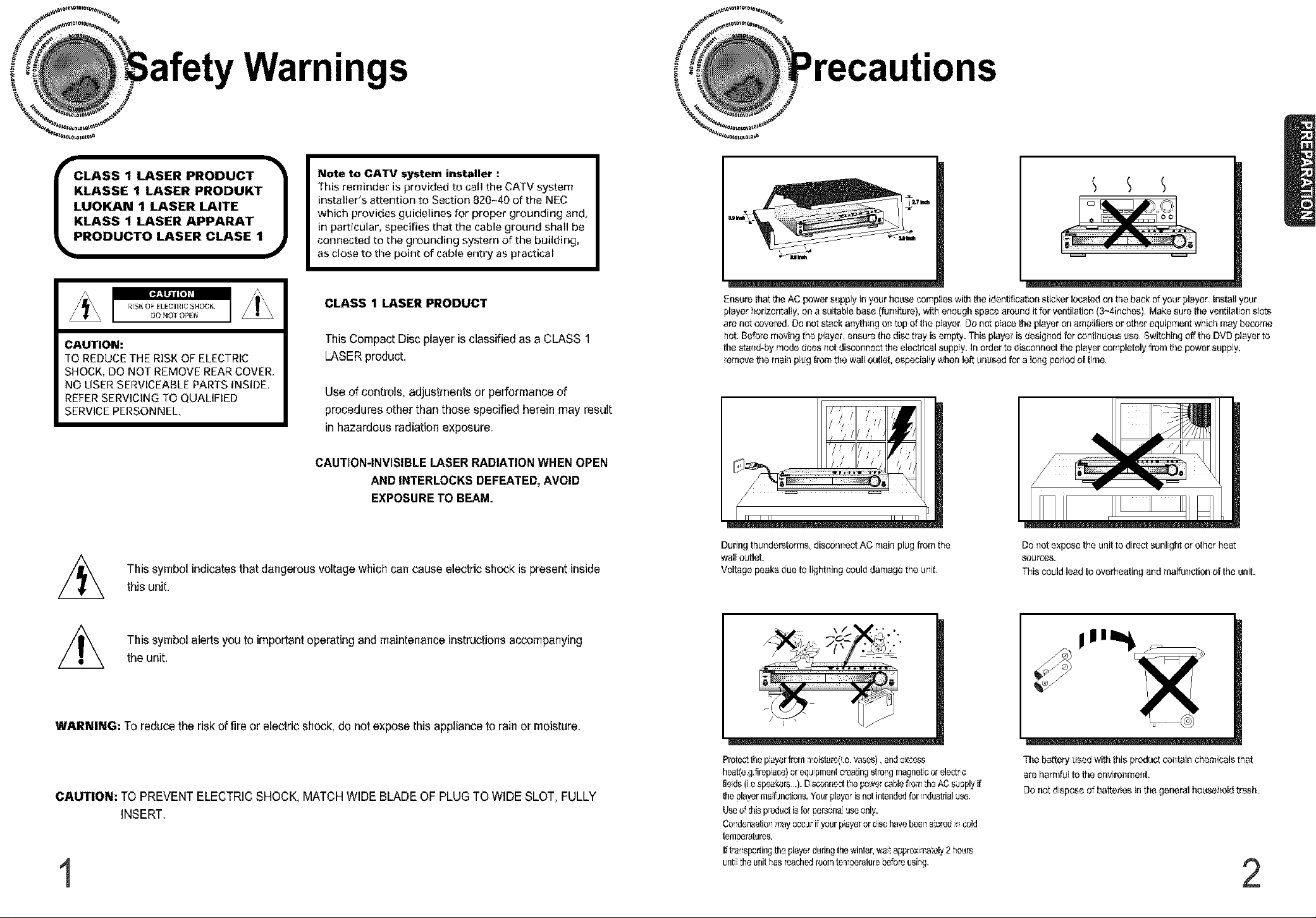
Ensure that the AC power supply in your house complies with the ide[_tificationsticker I_ted on the back of your player, Install your
player horizontally, on a suitable base (fur_iture), with e_ough space around it for ventilation (3~4i_ches), Make sure the ventilation slots
are not covered, Do not stack ar_ythingor_topof the player, Do not placethe player on amplifiers er other equipment which [nay become
hot. Before movir_gthe player, ensure the disc tray is empty. This player is designed for cor_tinuoususe.Switchir_goff the DVDplayer to
the sta_d-by mode does trot disconnect the electrical supply. Irlorder to discor_r_actthe player completely from the power supply,
remove the mair_plug from the wall outlet, especially wher_left ur_usedfor a Ior_gperiod of titus,
,///_ This symbol indicates that dangerous voltage which can cause electric shock is present inside
this unit.
This symbol alerts you to important operating and maintenance instructions accompanying
the unit,
WARNING: To reduce the risk of fire or electric shock, do not expose this applianceto rainor moisture,
CAUTION: TO PREVENT ELECTRIC SHOCK, MATCH WIDE BLADEOF PLUGTO WIDE SLOT, FULLY
INSERT,
1
Duringthu_;dars orms, discor_r;ectAC mair_plug from the
wall outlet.
Voltage peaks due to light[ring could damage the u[fit,
Protcc:tile payorfromrioistur0(.e,vsess), andexcess
heat_egtirepass)or equprns[_tcreatingstro_gmagnetcor eledrc
fieds (ia speakers.). Dscot,nedt_e ps,_ercablefro_ theAOsegplyif
the slayerrsefJncticos.Yourplayerisfist intendedfor rdusttialuse
Useof :hisproductisfor _rsena useo[dy.
Co densatior__ay occurifyour payer ordisc havebeo_s:oredr_cold
tern_ratures.
Ift_ar_sporiingtheplayerduringthewinter,wet approx,_a_ely2 _ours
urti the unitas _aCflC_roo[_tem_rature bo'o_ usi hg.
Do [_ot expose the ur_itto dircct sunlight or other heat
SOUrCeS.
This could lead ooverheati[_g a[_d malfu[_e io[_ of he uni.
The battery used with this product cor_tainchemicals that
are l_armful to the erwiror_me[_t,
Do not dispose of batteries in the general householdtrash.
2
Instructions
READ INSTRUCTIONS
All the safety and operating instructions should be
road before the appliance is operated.
RETAIN INSTRUCTIONS
The safety and operating instructions should be
retained for future reference.
HEED WARNINGS
All warnings on the appliance and in the operating
instructions should be adhered to.
FOLLOW INSTRUCTIONS
All operating and use instructions should be
followed.
WATER AND MOISTURE
Do not use this video product near water-
foroxample, near a bathtub, wash bowl,
kitchen sink, or laundry tub, in a wet basement,
or near a swimming pool, and the like.
OVERLOADING
Do not ovodoad wall outlets and extension cords as
this can result in the risk of fire
or olectdc shock.
VENTILATION
Slots and openings in the cabinet are provided
for ventilation and to ensure reliable operation of the
video product and to protect it from overheating
these openings must not be blocked or covered.
The openings should never be blocked
by placing the video product on a bed, sofa, rug, or
other similar surface. This video product
should never be placed near or over a radiator or
heat register.
This video product should not be placed
in a built-in installation such as a bookcase
or rack unless proper ventilation is provided
or the manufacturer's instructions have been
followed.
POWER CORD PROTECTION
Power-supply cords should be routed so that
they are not likely to be walked on or pinched
by items placed upon or against them paying
particular attention to cords at plugs,
convenience receptacles, and the point where
they exit from the appliance.
CLEANING
Unplug this video product from the wall outlet
before cleaning. Do not use liquid cleaners
or aerosot cleaners. Use a damp ctoth for cleaning.
LIGHTNING
For added protection of this video product
receiver during a lightning storm, or when
it is left unattended and unused for long
periods of time, unplug it from the wall outlet
and disconnect the antenna or cable system.
This will prevent damage to the video product
due to lightning and power-line surges.
OBJECT AND LIQUID ENTRY
Never push objects of any kind into this
product through openings as they may touch
dangerous voltage points or short-out parts
that could result in a fire or electric shock.
Never spill liquid of any kind on the video
product.
ACCESSORIES
Do not place this video product on an unstable cart,
stand, tripod, bracket, or table.
The video product may fall, causing serious injury to
a child or adult, and serious damage
to the appliance.
Use only with a cart, stand, tripod, bracket,
or table recommended by the manufacturer,
or sold with the video product. Any mounting
of the appliance shoutd foltow the manufacturer's
instructions and should use a mounting accessory
recommended by the manufacturer.
CART
An appliance and cart combination should be moved
with care. Quick stops, excessive force, and uneven
surfaces may cause the appliance and cart
combination to overturn.
POWER SOURCES
This video product should be operated only from the
type of power source indicated
on the marking label. If you are not sure
of the type of supply to your home, consult your
appliance dealer or local power company.
For video products intended to be operated from
battery power, or other sources, refer
to the operating instructions.
POWER LINES
An outside antenna system should not be located in
the vicinity of overhead power lines or other electric
light or power circuits,
or where it can fall into such power lines
or circuits. When installing an outside antenna
system, extreme care should be taken to keep from
touching such power lines or circuits as contact with
them might be fatal.
POLARIZATION
This video product is equipped with a poladzed
alternating current line plug (a plug having one blade
wider than the other.) This plug will fit into the power
outlet only one way.
This is a safety feature. If you are unable
to insert the plug futly into the oufiet, try reversing the
plug. If the plug should still fail to fit, contact your
electrician to replace your obsolete outlet. Do not
defeat the safety purpose of the polarized plug.
OUTDOOR ANTENNA GROUNDING
• If an outside antenna is connected to the
antenna terminal, be sure the antenna system
is grounded so as to provide some protection
against voltage surges and built-up static
charges.
• In the U.S.A section 810 of the National
Electrical Code, ANSI/NFPA No. 70-1984,
provides information with respect to proper
grounding of the mast and supporting
structure, grounding of the lead-in wire
to an antenna discharge unit, size of grounding
conductors location of antenna discharge unit,
connection to grounding electrodes, and
requirements for the grounding electrode.
See the figure below.
ATTACHMENTS
Do not use attachments not recommended
by the video product manufacturer as they may
cause hazards.
SERVICING
• Do not attempt to service this product yourself
as opening or removing covers may expose
you to dangerous voltage or other hazards.
• Refer all servicing to qualified servicepersonnel
REPLACEMENT PARTS
When replacement parts are required, be sure the
service technician has used replacement parts
specified by the manufacturer or having the same
characteristics as the odginal part. Unauthorized
substitutions may result in fire, electric shock or other
hazards.
SAFETY CHECK
Upon completion of any service or repairs
to this video product, ask the service technician to
perform safety checks to determine that the video
product is in proper operating condition.
DAMAGE REQUIRING SERVICE
Unplug this video product from the wall outlet and
refer servicing to qualified service personnel under the
following conditions.
a. When the power-supply cord or plug is damaged.
b. If liquid has been spilled, or objects have
fallen into the video product.
c. If the video product has been exposed to rain
or water
d. tf the video product does not operate normalty
by following the operating instructions.
Adjust only those controls that are covered
by the operating instructions as an improper
adjustment of other controls may result
in damage and will often require extensive
work by a qualified technician to restore
the video product to its normal operation.
e. If the video product has been dropped
or the cabinet has been damaged.
f. When the video product exhibits a distinct
change in performance - this indicates
a need for service.
HEAT
This video unit should be situated away from heat
sources such as radiators, stoves, or other products
(including amplifiers) that propduce heat.
3
4
OMulti-Disc Playback & AM/FM Tuner
The HT-DB390combines the convenienceof multi-disc p_aybackcapabi ty,
including DVD,CD, MP3-CD,CD-R/RW.and DVD-R/RW,with a soahisticated
AM/FM tuner, all in a single player.
OBuilt.in 5.1.Channel Amplifier
The HT-DB390 comes with a
allowingyou to enjoy
OSuper Digital Sound
Equipped with a new digital
calibration, magic sound
developed in cooperation wi!_
Japan, you'It enjoy a more li_
OSound Logo
When power is turned on, a sourid;logo is output from saeakers to
notify the user that the unt s optim'zed for dsc p,ayback.
OTV Screen Saver Function
The HT-DB390 automatically brightens and darkens the brightness of
the TV screen after 2 minutes in the stop or pause mode.
The HT-DB390 automatically switches itself into the power saving mode
after 20 minutes in the screen saver mode.
O Power Saving Function
The HT-DB390automatically shuts itself offafter 20 minutes
in the stop or pause mode.
O PREPARATION
Safety Warrfl[_gs.........
Pr_utEons ..........
SaFetyInstructions
Features.............
......................... 13
_,itt _ t118La[iguage ......................................................................................................................................... 37
_I_J_g TV 8_ _O ........................................................................................................................................... 39
_tli g Parer;tal Controls Rating Level ............................................................................................................... 41
S_t[i g the Password ..................................................................................................................................................... 43
Setting he Walbapsr ................................................................................................................................................. 45
Soding the Speaker Mode ............................................................................................................................................. 47
Setlinfl the Test Tone ................................................................................................................................................. 48
Setting the Delay Time........................................................................................................................................................ 49
Setting the Audio Quality .................................................................................................................................................... 51
Setting the DRC (Dynamb Range Compression) ............................................................................................................... 53
Auto Sound Calibration Setup............................................................................................................................................. 55
Magic Sound Field Mode .................................................................................................................................................... 57
Dolby Pro Logic II Mode...................................................................................................................................................... 59
Dolby Pro Logic II Effect ..................................................................................................................................................... 60
O RADIO OPERATION
Listonir_gto Radio ............................................................................................................................................................... 61
Presetting Stations .............................................................................................................................................................. 62
19
21
OCustomized TV Screen Display
The HT-DB390allows you toselect your favoriteimage during JPEG,
DVDplaybackand set it as your backgroundwallpaper.
5
Convenient Functions ......................................................................................................................................................... 63
Operating a TV with the Remote Control............................................................................................................................ 65
Before Calling for Service ................................................................................................................................................... 67
Cautions on HarJdlirJgand StorirJgDiscs ............................................................................................................................ 69
Specifications ...................................................................................................................................................................... 70
Notes or_Terminology ......................................................................................................................................................... 71
Warranty ............................................................................................................................................................................. 72
6
on Discs
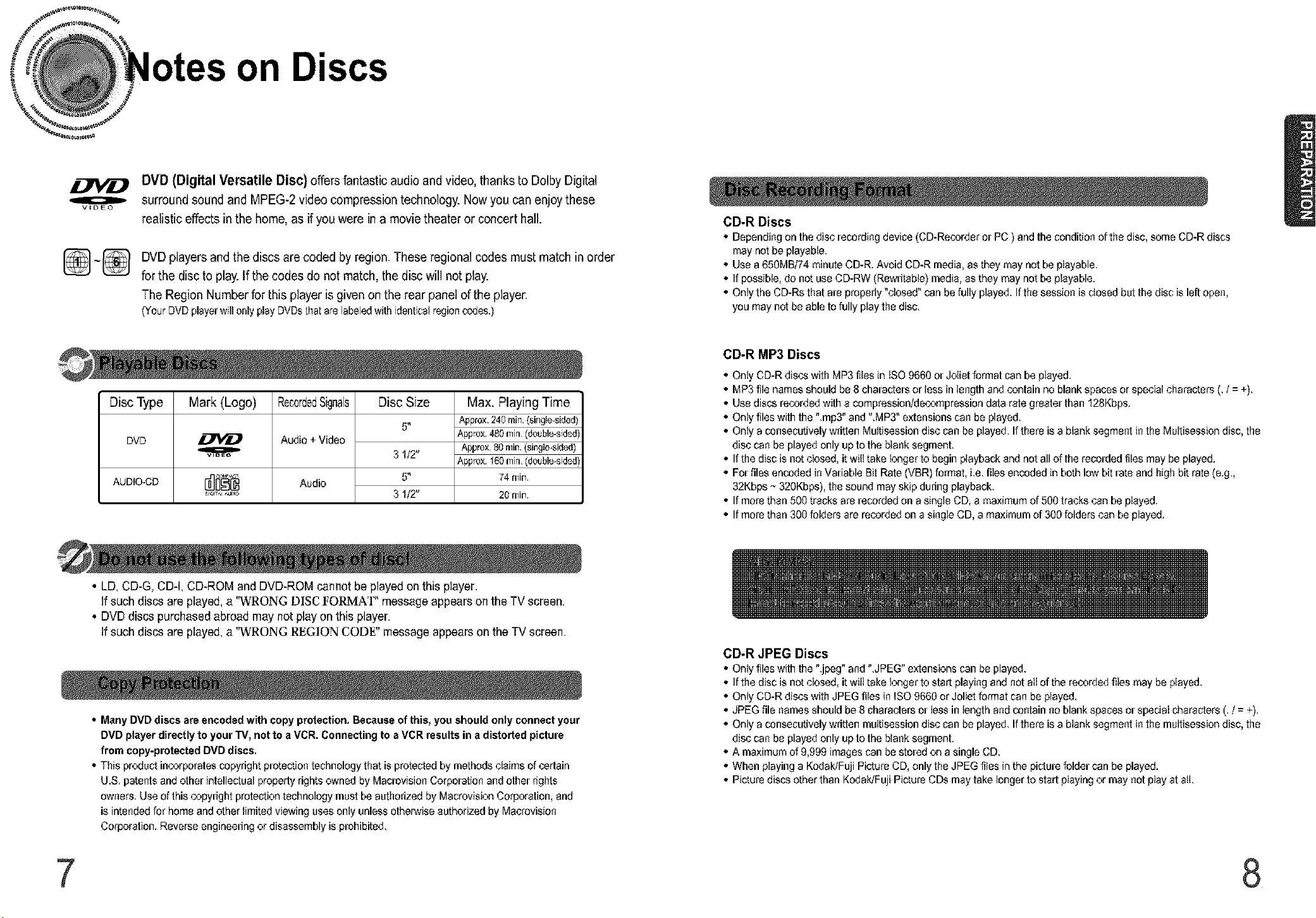
DVD (Digital Versatile Disc) offers fantastic audio and video, thanks to Dolby Digital
o
V_L3EO
_] _(_ DVDplayers and the discs are coded by region. These regional codes must match in order
surround sound and MPEG-2 video compression technology. Now you can enjoythese
realistic effectsin the home, as ifyou were in a movie theater or concert hall.
for the disc to play.If the codes do not match, the disc will not play.
The Region Number for this player is given on the rear panel of the player.
(YourDVDplayerwill only playDVDsthatarelabeledwithidenticalregioncodes.)
Disc Type
DVD
AUDIO.CD
Mark (Logo)
o
VIDEO
RecordedSignals
Audio+Video
Audio
Disc Size
5"
3I/2"
5"
3I/2"
Max. Playing Time
Approx.240mirl.(sirlgle_sided)
Approx.480[T)il),(double-sided)
Approx,80nlin,(single-sided)
Approx.'_eomill,(double-sided)
74mirl.
20 min.
CD-R Discs
• Depending on the disc recording device (CD-Recorder or PC ) and the condition of the disc, some CD-R discs
may not be playable.
• Use a 650MB174minute CD-R. Avoid CD-R media, as they may not be playable.
• If possible, do not use CD-RW (Rewritable) media, as they may not be playable.
• Oniy the CD-Rs that are properly "ctosed" can be fully played. If the session is closed but the disc is left open,
you may not be able to fully playthe disc.
CD-R MP3 Discs
• Onty CD-R discs with MP3files in ISO 9660 or Joliet format can be played,
• MP3 file names should be 6 characters or less in length and contain no blank spaces or speciat characters (, /= +),
• Use discs recorded with a compression/decompression data rate greater than 128Kbps,
• Onty files with the ",mp3" and "MP3" extensions can be played.
• Onty a consecutively written Muitisession disc can be played, Ifthere is a btank segment in the Muttisession disc, the
disc can be played only up to the btank segment.
• If the disc is not closed, it witl take iooger to begin playback and not all of the recorded files may be played.
• For files encoded in Variable Bit Rate (VBR) format, i,e. flies encoded in both low bit rate and high bit rate (e,g.,
32Kbps ~ 320Kbps), the sound may skip during playback.
• If more than 500 tracks are recorded on a single CD, amaximum of 500 tracks can be played,
• If more than 300 fotders are recordedon a singte CD, a maximum of 300 folders can be played,
• LD,CD-G, CD-I, CD-ROM and DVD-ROM cannot be played on this player.
If such discs are played, a '"WRONG D][SCltORNIA']" messageappears on the TV screen.
• DVDdiscs purchased abroad may not playon this player.
If such discs are played, a '"WRONG R£G][ON COD£" message appearson the TV screen.
CD-R JPEG Discs
• Onty files with the ".jpeg" and ".JPEG" extensions can be played.
• If the disc is not closed, it witl take tooger to start playing and not att of the recorded flies may be played.
• Onty CD-R discs with JPEG flies iniSO 9660 or Joliet format can be played.
• Many DVD discs are encoded with copy protection. Because of this, you should only connect your
DVD player directly to your TV, not to a VCR. Connecting to a VCR results in a distorted picture
from copy-protected DVD discs.
• This produc_incorporatescopyright protection technology that is protected by methods claims of certain
U.S, patents and other intellectual properly rights owned byMacrovision Corporation and other rights
owners, Use ofthis copyright protection technology must be authorized by Macrovision Corporation, and
is intendedfor home and other limited viewing uses only unless otherwise authorized by Macrovision
Corporation, Reverse engineering or disassembly is prohibited,
• JPEG file names should be 8 characters or iess in ieogth and contain no blank spaces or speciat characters (. / = +).
• Onty a consecutively written multisession disc can be played. Ifthere is a btank segment in the muttisession disc, the
disc can be played only up to the btank segment.
• A maximum of 9,999 images can be stored on a single CD.
• When playing a Kodak/Fuji Picture CD, only the JPEG files in the picture folder can be played.
• Picture discs other than Kodak/Fuji Picture CDs may take longer to start playing or may not play at nil
7 8
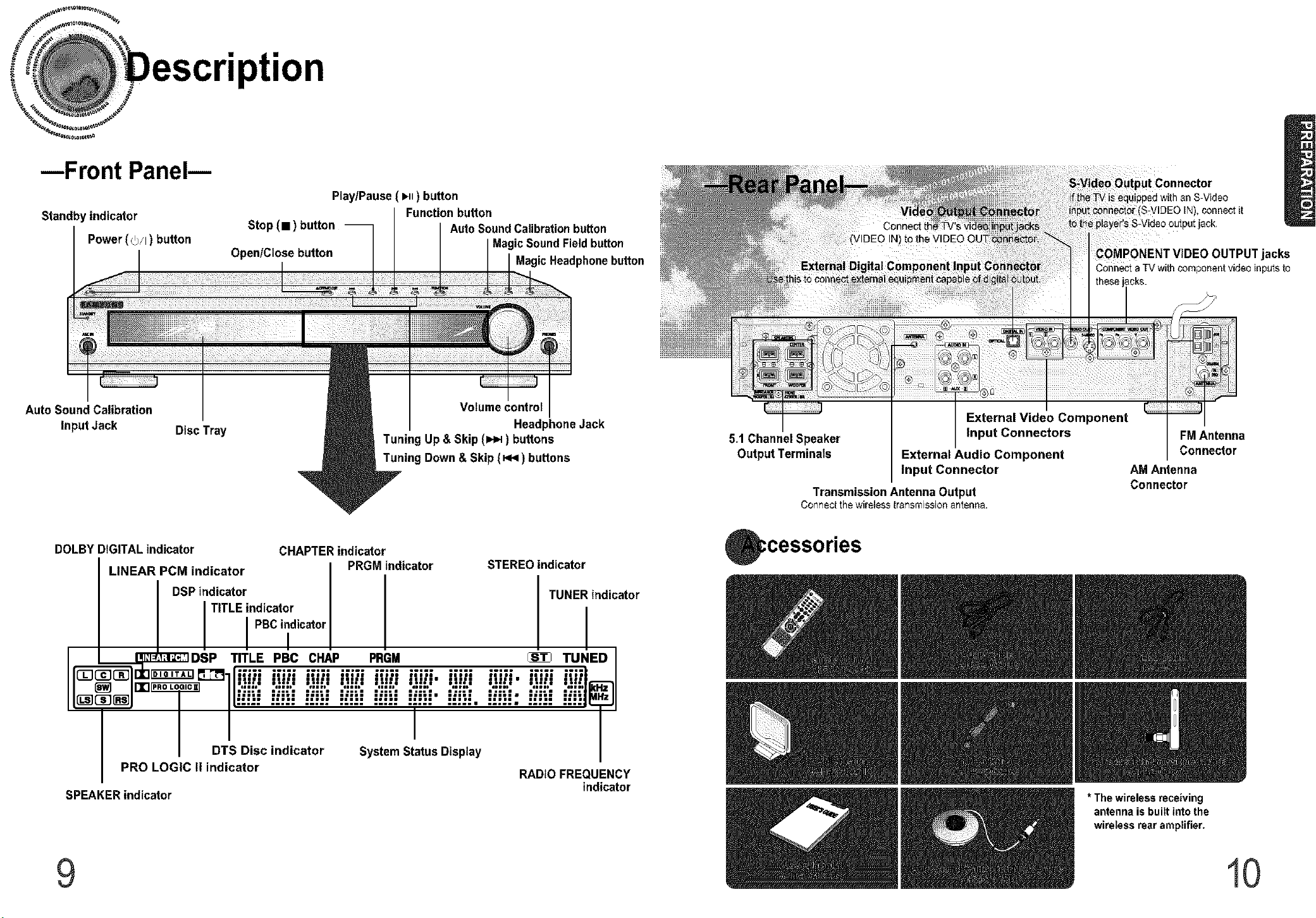
--Front Panel--
Standby indicator
Power (_/I ) button
Auto Sound Calibration
Input Jack
DOLBY DIGITAL indicator CHAPTER indicator
LINEAR PCM indicator PRGM indicator STEREO indicator
Disc Tray
Stop (11) button -- AutoSoundCalibrationbutton
Open/Close button MagicHeadphonebutton
Play/Pause (i_H) button
Function button
Tuning Up & Skip (I,,.1_) buttons
Tuning Down & Skip (_,q ) buttons
MagicSoundFieldbutton
Volume control
Headphone Jack
5.1 ChannelSpeaker
Output Terminals
Transmission Antenna Output
ConnectthewirelesstransmLssionantenna.
;cessories
External Video Component
Input Connectors
External Audio Component
Input Connector
I),connectit
_)OUTPUT jacks
CohnectaTVwithcomponentvideoinputsto
FM Antenna
Connector
AM Antenna
Connector
DSP indicator TUNER indicator
I I TITLE indicator I
PBCindicator
/
rI_J_E_DSP TITLE PBc CHAP PRGM _ TUNED
.................................................
' ,,,,,"''" ,,,,,"''" ,,,,,""" ,,,,,"''" ,,,,,""" i'|'-'= ,,,,,"''" i'|'-'= ,,,,,"''" ,,,,"'',
I I D t i I b i i I b ulm ulm ullP UIll
:-:-; 1-,-: 1-,;- ;-:-1 :-:-; 1,,-: 1-,-:, 1-,-:, 1-,-: 1-,;
/ DTS Disc indicator System Status Display
PRO LOGIC II indicator RADIO FRE(;UENCY
SPEAKER indicator indicator
I.=.l I,..I I,..= I...
I
9
* The wireless receiving
antenna is built into the
wireless rear amplifier.
10
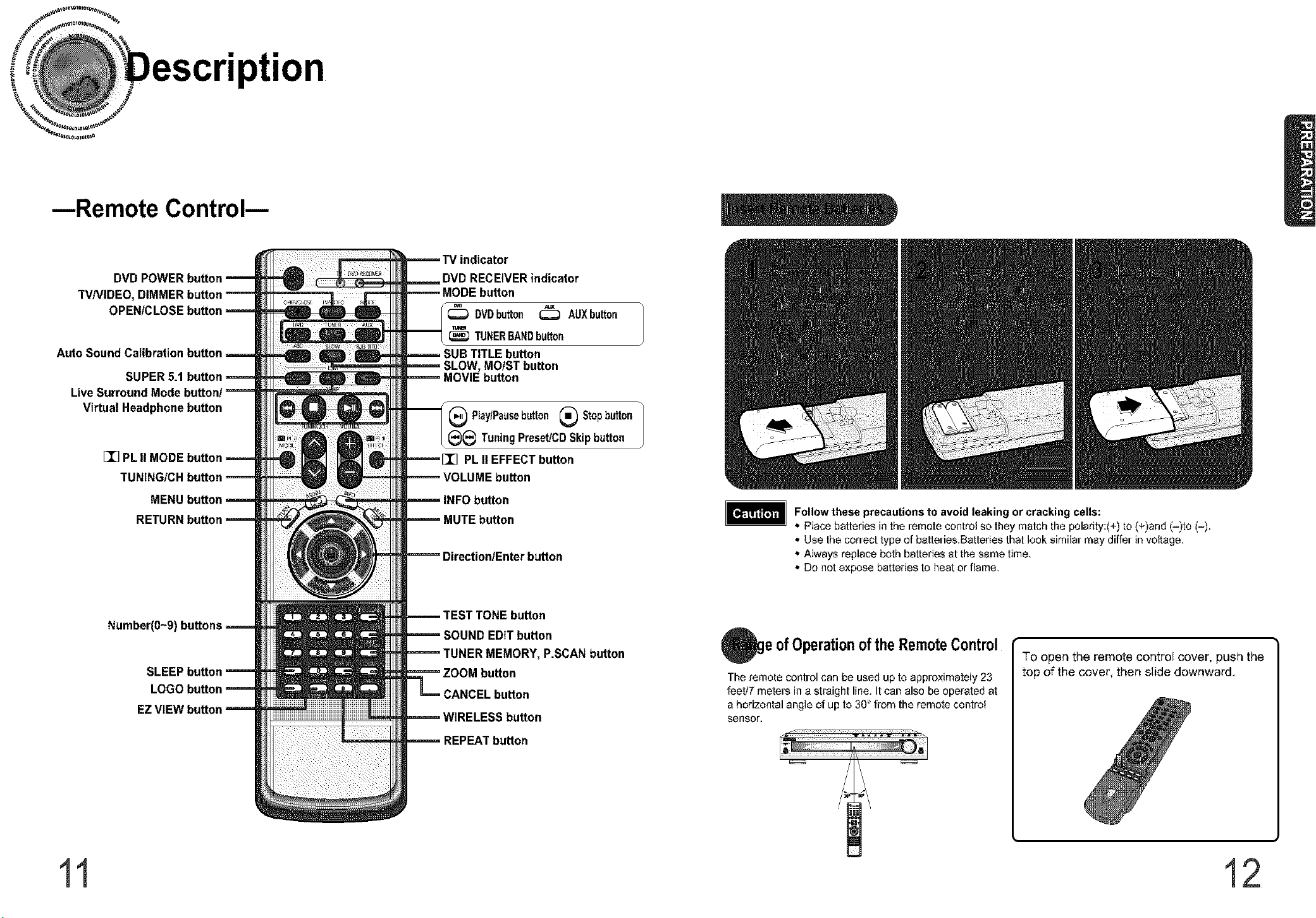
--Remote Control--
TV indicator
DVD POWER button DVD RECEIVER indicator
TVNIDEO, DIMMER button _ m_tl_ _tl_u MODE button
OPENICLOSEbutton= _ _ DVDbutton _ AUXbutton
Auto Sound Calibration button _ _ _ _ SUB TITLE button
SUPER 5.1 button = _ _ MOVIE button
Live Surround Mode button/-- -- --_ .....................
Virtual Headphone button I Play/Pausebutton _ Stopbutton
[]_ PLII
MENI
RET!
Number(0~9)
EZ VIEW I
SLOW, MOIST button
(_ TuningPreset!CDSkipbutton
PLII EFFECT button
button
button
button
EDIT button
INER MEMORY, P.SCAN button
button
button
)utton
Follow these precautions to avoid leaking or cracking cells:
• Place batteries in the remote control so they match the polarity:(+) to (+)and (-)to (-).
• Use the correct type of batteries.Batteries that look similar may differ in voltage,
• Always replace both batteries at the same time,
• Do not expose batteries to heat or flame,
ofOperationoftheRemoteControl
The remote control can be used up to approximately 23
feetl7 meters in a straight line. Itcan also be operated at
a horizontal angle of up to 30° from the remote control
sensor.
To open the remote control cover, push the
top of the cover, then slide downward.
11 12
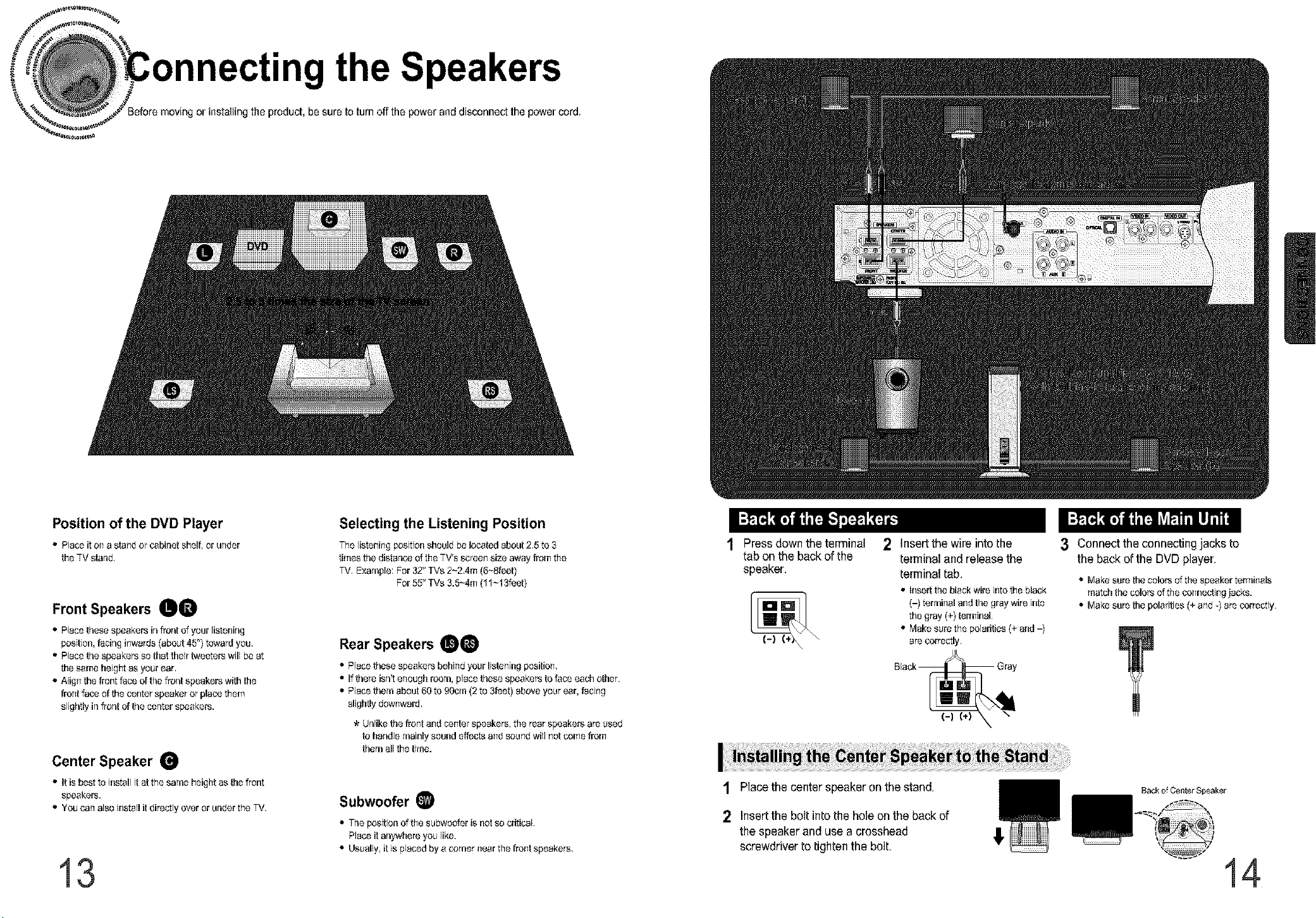
mnecting the Speakers
or installing the product, be sure to turnoff the power and disconnecl the power cord.
Position of the DVD Player
• Place it oil a stalld or cabklet shelf, or ulldar
the TV stared.
Front Speakers gO
• Place thosespeakers ir_fror_tof your listenirlg
position, Pacirlgillwards (about 45_)toward you,
• Place the speakers so that theirtweeters will be at
the same height as your ear,
• Align the front face of the frorlt speakers with the
freestface of the cantor speaker or place them
slightly ir_frer_tof the cer_terspeakers.
Center Speaker
• It is best o k_stall i at the same height as be fron
speakers.
• You ca_ also i[_stallit directly over or ur_derthe TV.
13
Selecting the Listening Position
Tile lista[lillg position should be I_tod about 2,5 to 3
times the distar_ceof the TV's scree_ size away from the
TV. Example: For 32" TVs 2~2Am (6~Bleat)
For 55" TVs 3.5~4m (11~13f@t)
Rear Speakers _
• Place these speakers behind your listenk_g pasitior_.
• If there isrft ellougb roola, place these speakers to face each other,
• Place thole about 60 to 90cla (2 to 3feet) above your ear, facillg
sligtltly downward,
Ur_likethe freestarid cer_terspeakers, the rear speakers are used
to bar,die mainly sound effects a_d sou_d will _ot come from
them all the time.
Subwoofer
The position of the subwoofer is notso criticak
Place it ar_ywbereyou like.
• Usually, it is placed by a carrier near the front speakers,
Press down the terminal
tab on the back of the
speaker,
\
2 Insert the wire into the
terminal and release the
terminal tab,
• Insert the black wire iratethe black
(-) termk_aland the gray wire into
the gray (+) termi[_al,
• Make sure the polarities (+ and -)
are correctly,
Black_ Gray
t Placethe center speaker on the stand.
Insertthe bolt into the hole on the back of
the speaker and use a crosshead
screwdriver to tighten the bolt,
3 Connect the connectingjacks to
the back ofthe DVD player,
• Make sure the colors of the speaker termk_als
ma cb he colors ofthe cermet'ring lacks.
• Make sure tile polarities (+ arid -) are correctly,
Back of Center Speaker
!
14
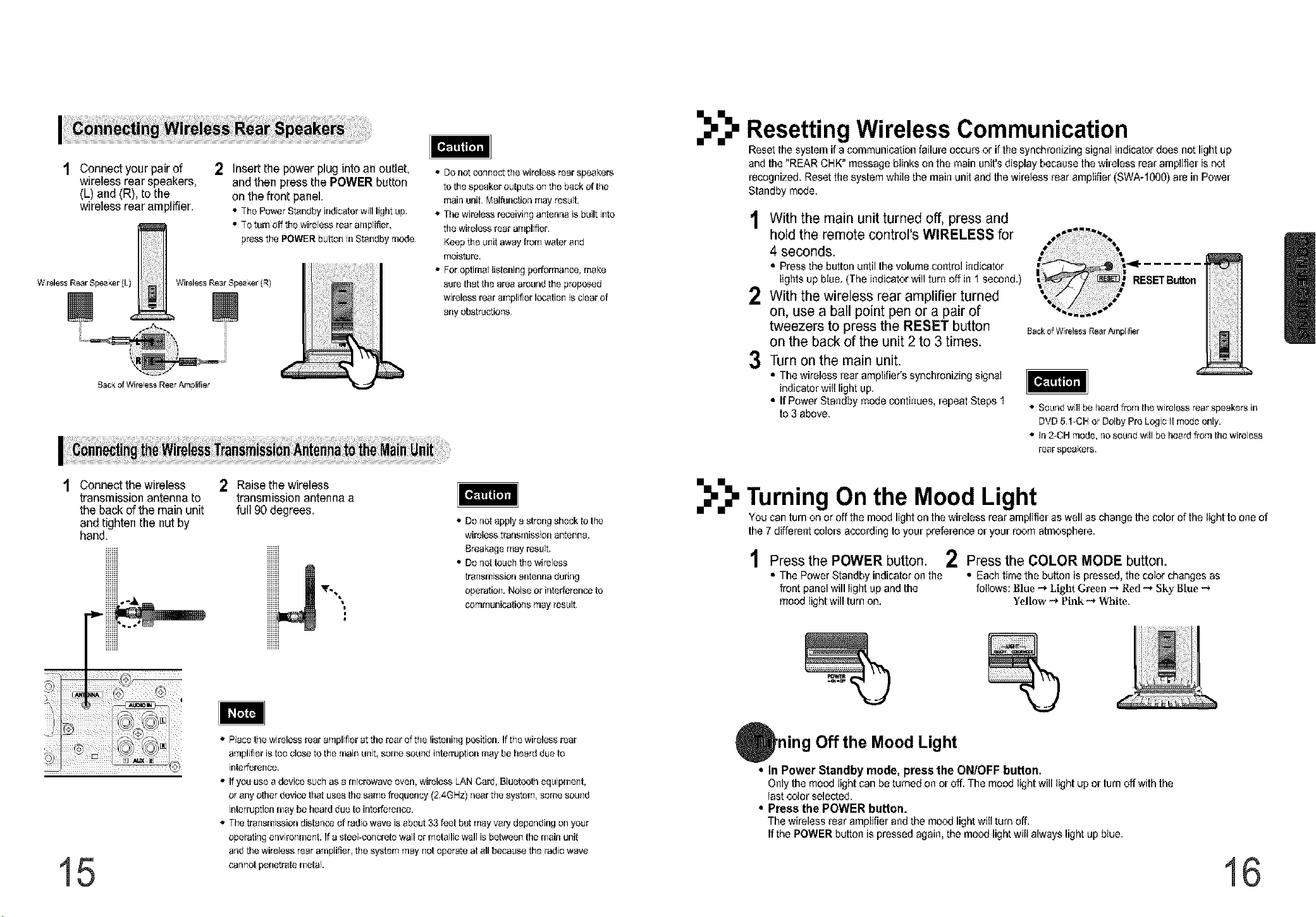
t Connect your pair of
wireless rear speakers,
(L) and (R), to the
wireless rear amplifier.
W reless Rear Spea_er (Lt
Back of Wire ess Rear Anplifier
Z
Wireless Rear Speaker (R)
2 Insert the power plug into an outlet,
and then press the POWER button
on the front panel.
• 7he PowerStandbyindicatorwilllightup,
• 70tam offthewirelessrearamplifier,
pressthePOWERbuttonJrlStandbylaode,
• DOnot osfmect the wireless rear speakers
to the speaker outputs o_ the back of the
mair_unit, Malfunetior_may result.
• The wireless r_eivk_g a_ter_r_eisbuilt into
the wireless rear amplifier.
Keep the unit away from water end
moisture.
• For optimal listening per_ormacee,make
sure thatthe area areur_dthe proposed
wireless rear amplifier I_tion is clear of
any obstructio_rs,
Resetting Wireless Communication
Reset the system if a communication failure occurs or ifthe synchronizing signal indicator does not light up
and the "REAR CHK" messageblinks on the main unit's display because the wireless rear amplifier is not
recognized. Resetthe system while the main unit and the wireless rear amplifier (SWA-1000) are in Power
Standby mode.
1 With the main unit turned off, press and
hold the remote control's WIRELESS for
4 seconds.
• Press the button until the volume control indicator
lights up blue. (The indicator wiltturn off in 1 second.)
2 With the wireless rear amplifier turned
on, use a ball point pen or a pair of
tweezers to press the RESET button
on the back of the unit 2 to 3 times.
Turn on the main unit.
3
• The wireless rear amplifier's synchronizing signal
indicator witt light up,
• If Power Standby mode continues, repeat Steps 1
to 3 above,
Rack o_W reless Rear Arnpl tier
m
[_Jllgtv]_
• Souredwill be heard from the wireless rear speakers in
DVD 5.1-CH or Dolby Pro Logic IImode only.
• ]r_2-OH mode, r_osouredwill be heard from tile wireless
rear speakers,
Connect the wireless
transmission antenna to
the back of the main unit
and tighten the nut by
hand,
15
2 Raise the wireless
transmission antenna a
full 90 degrees,
• Place the wireless roar amplifier at the rear of the listeniog position. Ifthe wireless rear
amplifier is too close to the main u_it_seine sou_d i_terruptios [nay be bea_ due to
interfere_ce,
• If you use e device such as a [nicrowave overL wireless LAN Card, Bluetooth equip[nellt,
or any o{ber device that uses the same frequency (2,4GBz) r_eerthe systerrl_seine sou_d
interruption [nay be beard due to ir_terference.
• The tra[_smissior_distar_ceof radio wave is about 33 f_t b_ rosy vary deper_dingon your
operathg er_viro_[ne_t. If a steePconcrete wall or metallic wall is between the main unit
arid the wireless roar amplifier, the system may _ot operate at ell because the radio wave
carcanetpenetrate metak
• Do r_otapply a strong shock to the
wireless traosmissios antenna,
Breakage may result,
• Do r_ottouch the wireless
tra_smissior_antenna duriog
operatio_. Noise or ir_terferenceto
communicatiof_s may result,
TurningOn the Mood Light
You can turn on or off the mood light on the wireless rearamplifier as well as change the color of the light to one of
the 7 different colors according to your preference or your room atmosphere.
1 Press the POWER button. 2 Press the COLOR MODE button.
• The Power Standby indicator on the • Each time the button is pressed, the color changes as
front panelwill light up and the follows: Blue -_ Light Green _ R_I _ Sky Blue -_
mood light will turn on. Yellow -_ PI_ _ White,
ning Off the Mood Light
• tn Power Standby mode, press the ONfOFF button,
Only the mood light can be turned on or off. The mood light will light up or turn off with the
last color selected.
• Press the POWER button.
The wireless rear amplifier andthe mood light wilt turn off.
Ifthe POWER button is pressed again, the mood light witi always light up blue,
16
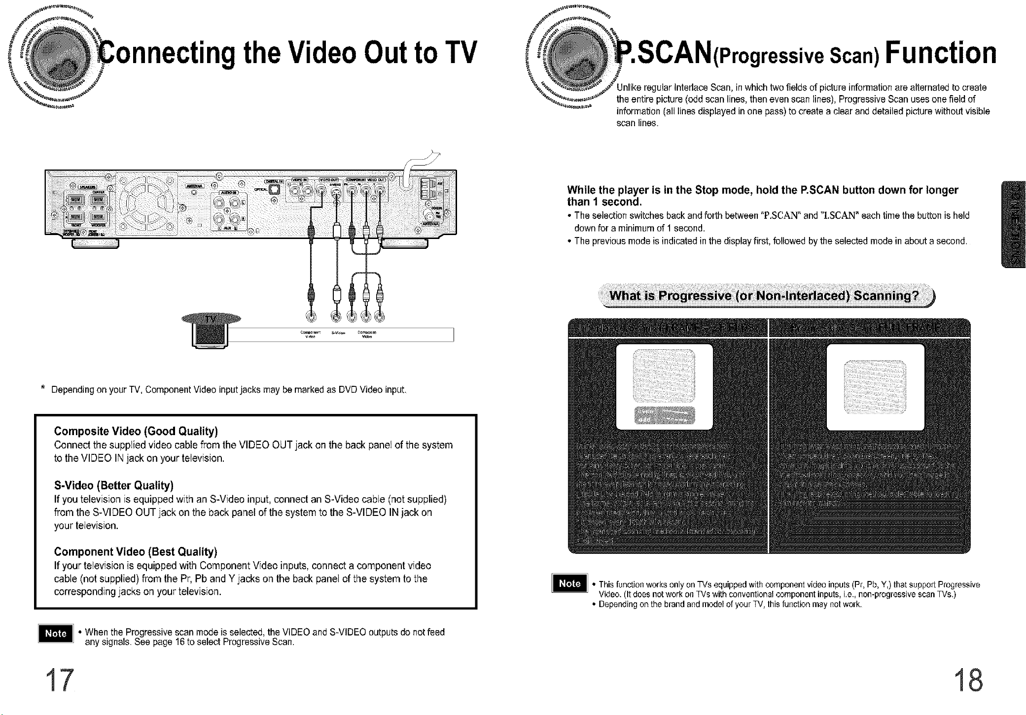
nectingtheVideoOuttoTV
ressive Scan) Function
ular Interlace Scan, in which two fields of picture information are alternated to create
the entire picture (odd scan lines, then even scan lines), Progressive Scan uses one field of
information (all lines displayed in one pass) to create a clear and detailed picture without visible
scan lines,
While the player is in the Stop mode, hold the P.SCAN button down for longer
than 1 second,
• The selection switches back andforth between "P.SC,AN" and "I.SCAN" eachtime the button is held
downfor a minimumof 1second,
• The previous mode is indicated in the displayfirst, followed by the selected mode in about a second,
* Dependingon your TV, Component Video inputjacks may be marked as DVD Video input,
Composite Video (Good Quality)
Connect the supplied video cable from the VIDEO OUT jack on the back panel of the system
to the VIDEO INjack on your television.
S-Video (Better Quality)
If you television is equipped with an S-Video input, connect an S-Video cable (not supplied)
from the S-VIDEO OUT jack on the back panel of the system to the S-VIDEO IN jack on
your television.
Component Video (Best Quality)
If your television is equipped with Component Video inputs, connect a component video
cable (not supplied) from the Pr, Pb and Y jacks on the back panel of the system to the
corresponding jacks on your television.
• When the Progressive scan modeis selected, the VIDEO and S-VIDEO outputs do not feed
any signals, See page 16to select ProgressiveScan,
• Thisfunction works only on TVs equipped with component video inputs (Pr, Pb, Y,) that suppori Progressive
Video. (It does not work on TVs with conventional component inputs, i.e., non-progressive scan TVs.)
• Depending on the brand and model of your TV,this function may not work.
17 18
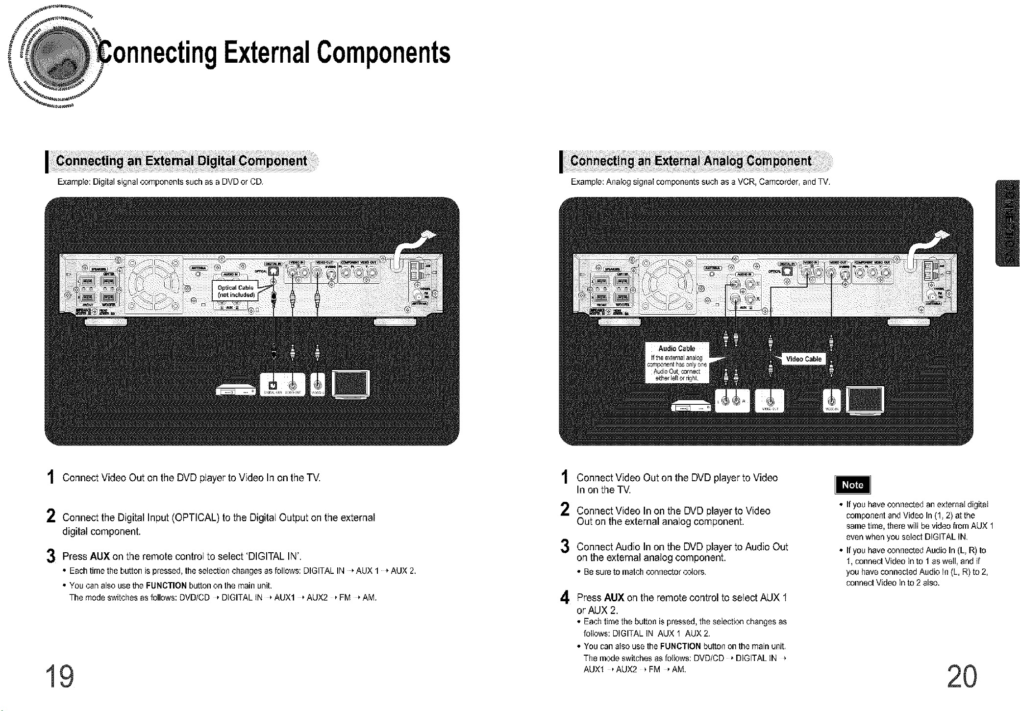
ngExternalComponents
Example: Digital signal components such as a DVD or CD, Example: Analog signat components such as a VCR, Camcorder, and TV.
1 Connect Video Out on the DVD player to Video In on the TV.
2 Connect the Digital Input (OPTICAL) to the Digital Output on the external
digital component.
3 Press AUX on the remote control to select 'DIGITAL IN'.
• Eachtimethebuttonispressed,theselectionchangesasfollows:DIGITALIN _AUX 1 _AUX2.
• Youcanalso usethe FUNCTIONbuttononthemainunit.
Themodeswitchesasfollows"DVDtCD DIGITALiN _AUX1 _AUX2 _FM _AM.
19
1
Connect Video Out on the DVD player to Video
In on the TV.
2
Connect Video In on the DVD player to Video
Out on the external analog component.
3
Connect Audio In on the DVD player to Audio Out
on the external analog component.
• Besureto matchconnectorcolors.
4
Press AUX on the remote control to select AUX 1
or AUX 2.
• Eachtimethebuttonispressed,theselectionchangesas
follows:DIGITALIN AUX1 AUX2.
• Youcanatsousethe FUNCTIONbuttonon themainunit.
Themodeswitchesasfollows:DVDICD _DIGITALIN
AUXI _AUX2 _FM _AM.
• Ifyou haveconnected an externat digitat
component and Video In(1, 2} atthe
same time, there witt be video from AUX 1
even when you select DIGITAL IN.
• If you have connected Audio In (L, R) to
I, connect Video In to 1 as well, and if
you have connected Audio In (L, R} to 2,
connect Video in to 2 also.
2O
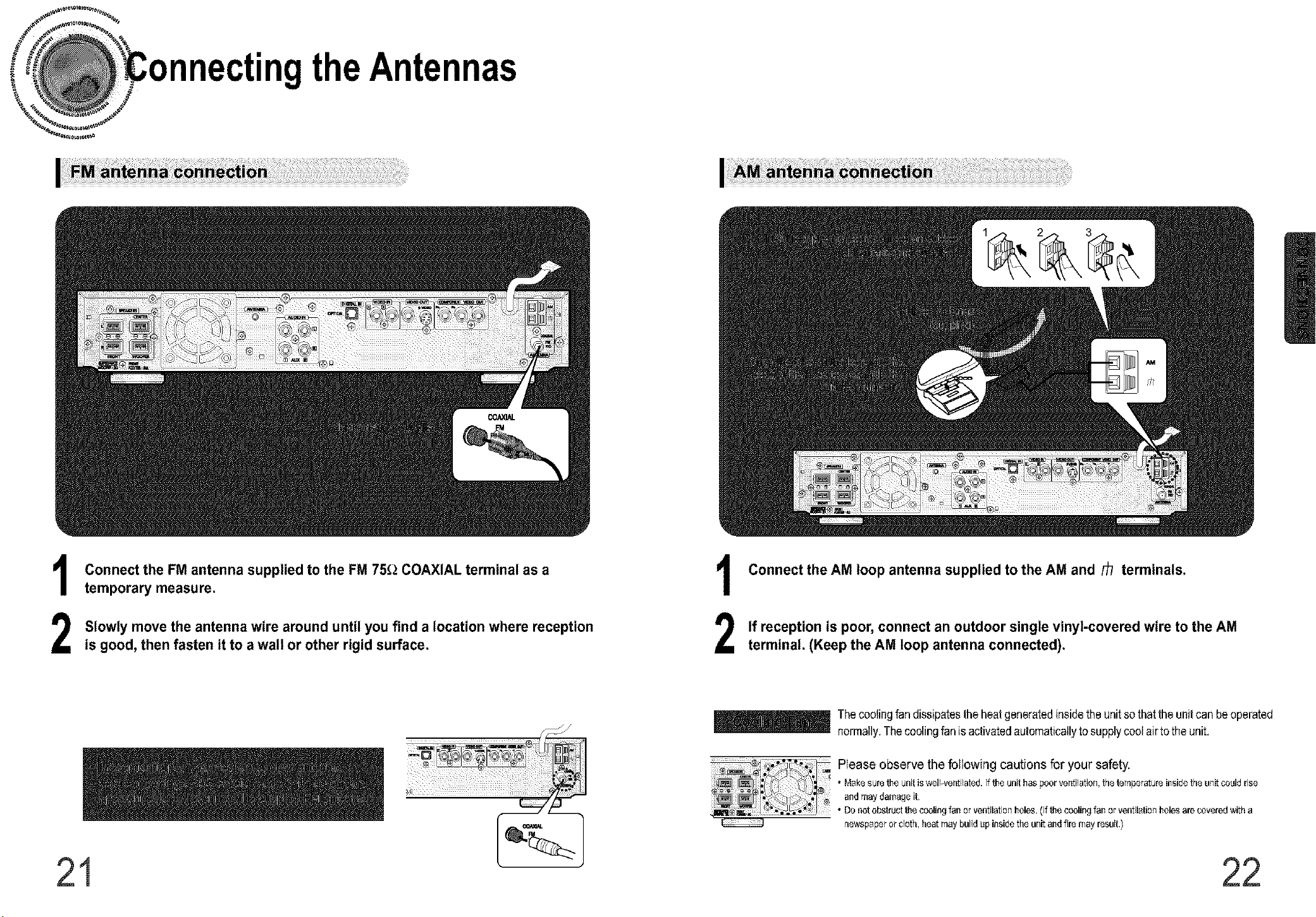
nectingtheAnten
Connect the FM antenna supplied to the FM 75_ COAXIAL terminal as a
1
temporary measure.
Slowly move the antenna wire around until you find a location where reception
2
is good, then fasten it to a wall or other rigid surface.
Connect the AM loop antenna supplied to the AM and _ terminals.
1
If reception is poor, connect an outdoor single vinyl-covered wire to the AM
2
terminal. (Keep the AM loop antenna connected).
_The coolingfan dissipatestheheatgeneratedinsidetheunitsothat theunit can beoperated
normally,Thecoolingfanisactivatedautomaticallytosupplycootairtothe unit,
Please observethe followingcautions for your safety.
• Makesure _e unit iswelPver=tilatod.If_e unithas poor ver=tilation,thetemperatureinsidethe unitcould rise
andmay danlageit,
• Dooot obstruct_e coolingfan or ventilationholes.(If _e coolingfanor ventilationholesare coveredwith a
rlewspaperor cloth, heat may build up insidethe unitandfire may result.)
21 22
 Loading...