

Samsung HT C5500 Service Manual
5.1CH Blu-ray
Home Theater System
Model Name : HT-C5500
Model Code : HT-C5500/XAX
Speaker PS-C5500
Front PS-FC5500
Center PS-CC5500
Rear PS-RC5500
Subwoofer PS-WC5500
SERVICE
Manual
5.1CH Blu-ray Home Theater System
HT-C5500
CONTENTS
1. Precaution
2. Product Specification
3. Disassembly & Reassembly
4. Troubleshooting
5. Exploded View & Part List
6. PCB Diagram
7. Schematic Diagram
Refer to the service manual in the GSPN (see the rear cover) for the more information.
GSPN (Global Service Partner Network)
Area Web Site
North America service.samsungportal.com
Latin America latin.samsungportal.com
CIS cis.samsungportal.com
Europe europe.samsungportal.com
China china.samsungportal.com
Asia asia.samsungportal.com
Mideast & Africa mea.samsungportal.com
This Service Manual is a property of Samsung Electronics
Co.,Ltd. Any unauthorized use of Manual can be punished
under applicable International and/or domestic law.
© Samsung Electronics Co.,Ltd. May. 2010
Printed in Korea

Contents
1. Precaution
1-1 Safety Precautions ...........................................................................................1-1
1-2 Servicing Precautions ......................................................................................1-3
1-3 Precautions for Electrostatically Sensitive Devices (ESDs) .............................1-4
2. Product Specification
2-1 Product Feature ...............................................................................................2-1
2-2 Specifications ...................................................................................................2-2
2-3 Specifications Analysis .....................................................................................2-6
2-4 Accessories ......................................................................................................2-9
3. Disassembly & Reassembly
3-1 Overall Disassembly & Reassembly ................................................................3-1
3-2 DECK Disassembly & Reassembly.................................................................. 3-6
4. Troubleshooting
4-1 Checkpoints by Error Mode.............................................................................. 4-1
4-2 Initialization & Upgrade Methods .....................................................................4-24
4-3 Buyer-Region Code Setting Method ................................................................4-27
5. Exploded View & Part List
5-1 Product Exploded View ....................................................................................5-1
5-2 DECK Exploded View ......................................................................................5-3
5-3 Speaker System ...............................................................................................5-5
5-4 Electrical Part List ............................................................................................5-6
6. PCB Diagram
6-1 Wiring Diagram ................................................................................................6-1
6-2 FRONT PCB Top ..............................................................................................6-2
6-3 KEY PCB Top ...................................................................................................6-4
6-4 AMP PCB Top ..................................................................................................6-6
6-5 AMP PCB Bottom .............................................................................................6-8
6-6 MAIN PCB Top .................................................................................................6-9
6-7 MAIN PCB Bottom ...........................................................................................6-12
6-8 SMPS PCB Top ................................................................................................6-14
6-9 SMPS PCB Bottom ..........................................................................................6-16

Contents
7. Schematic Diagram
7-1 Overall Block Diagram .....................................................................................7-1
7-2 FRONT .............................................................................................................7-2
7-3 KEY ..................................................................................................................7-3
7-4 AMP-1 ..............................................................................................................7-4
7-5 AMP-2 ..............................................................................................................7-5
7-6 AMP-3 ..............................................................................................................7-6
7-7 AMP-4 ..............................................................................................................7-7
7-8 ETHERNET / USB / WI-FI ................................................................................7-8
7-9 VIDEO / IPOD VIDEO ......................................................................................7-9
7-10 HDMI MICOM...................................................................................................7-10
7-11 HDMI RX .......................................................................................................... 7-11
7-12 HDMI TX .......................................................................................................... 7-12
7-13 NAND FLASH / CLOCK / BBS / JTAG ............................................................. 7-13
7-14 DDR3-1333 ......................................................................................................7-14
7-15 GPIO / BOOT STRAP / UART / RX_SW ..........................................................7-15
7-16 7630 POWER / DECOUPLING ........................................................................7-16
7-17 F/E OPU CONNECTION..................................................................................7-17
7-18 F/E MOTOR DRIVE .........................................................................................7-18
7-19 FRONT MICOM ............................................................................................... 7-19
7-20 DIR / ADC / RX SWITCHING / D.IN .................................................................7-20
7-21 DSP SDRAM / FLASH .....................................................................................7-21
7-22 DC-DC POWER ............................................................................................... 7-22
7-23 IPOD ................................................................................................................ 7-23
7-24 SMPS ............................................................................................................... 7-24
Precaution
1. Precaution
Follow these safety instructions while servicing the ESD to prevent damage and to protect against potential
hazards such as electrical shock and X-rays.
1-1 Safety Precautions
1. When reinstalling the chassis and its assemblies, be sure to restore all of the protective devices, including the
control knobs and the compartment covers.
2. Make sure that there are no cabinet openings through which people (particularly children) can make contact
with dangerous internal components.
3. Design Alteration Warning:
Never alter or add to the mechanical or electrical design of the unit.
Example: Do not add auxiliary audio or video connectors. Such alterations might create a safety hazard.
Also, any design changes or additions will void the manufacturer’s warranty.
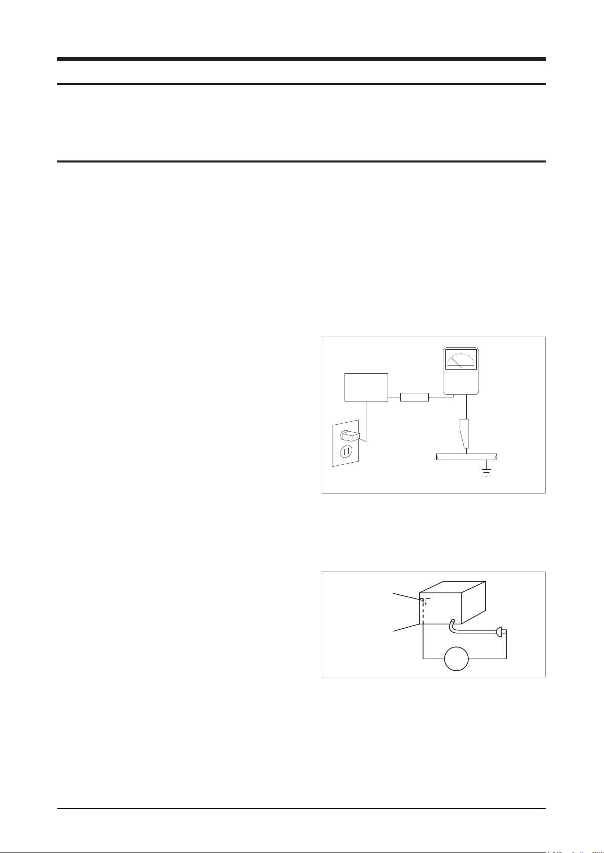
4. Leakage Current Hot Check (Fig. 1-1):
Warning: Do not use an isolation transformer during this
test. Use a leakage-current tester or a metering system
that complies with American National Standards Institute
(ANSI C101.1, Leakage Current for Appliances), and
Underwriters Laboratories (UL Publication UL1410,
59.7).
With the unit completely reassembled, plug the AC cord
directly into a 120V AC outlet. With the unit’s power
switched from the ON to the OFF position, measure the
current between a known ground and all exposed metal
DEVICE
UNDER
TEST
TEST ALL
EXPOSED METAL
SURFACES
2-WIRE CORD
ALSO TEST WITH
PLUG REVERSED
(USING AC
ADAPTER PLUG
AS REQUIRED)
<Fig. 1-1 AC Leakage Test>
LEAKAGE
CURRENT
TESTER
(READING
SHOULD NOT BE
ABOVE 0.5mA)
parts.
Known Grounds - Earth
Known Metal parts - screwheads, metal cabinets, etc.
EARTH
GROUND
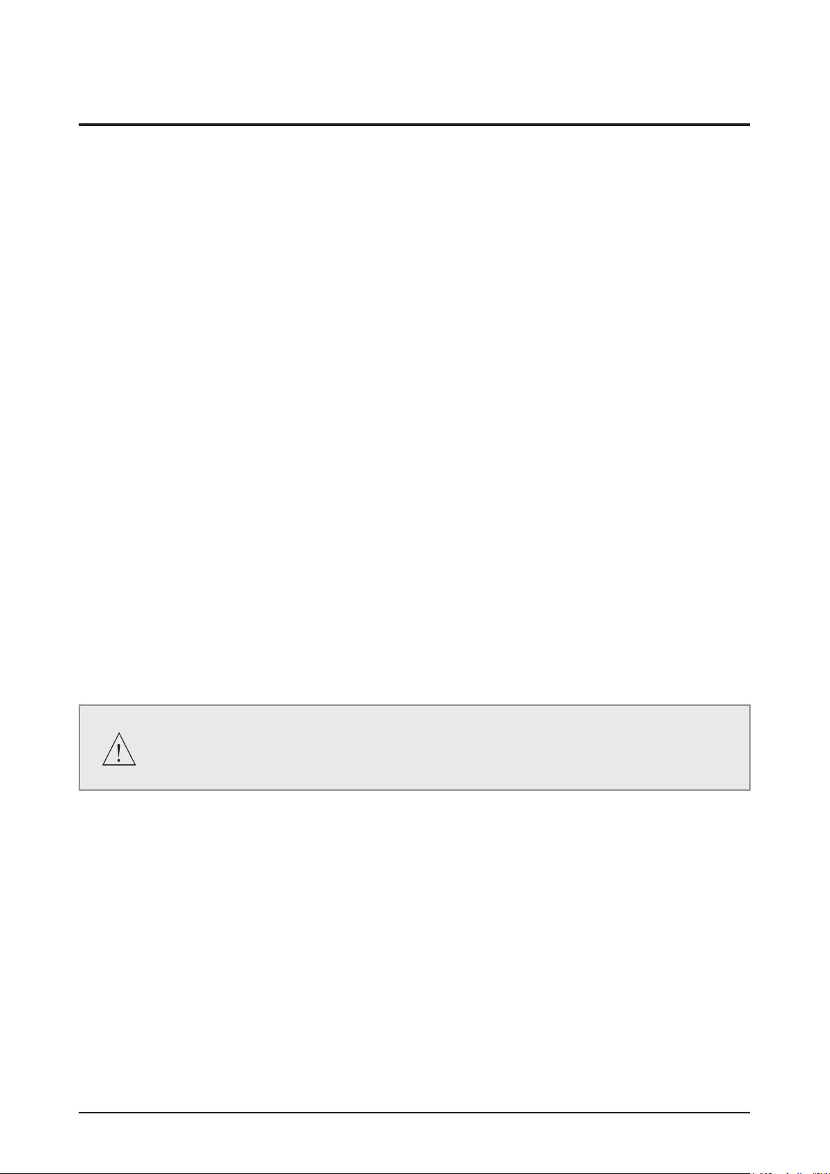
5. Insulation Resistance Cold Check:
(1) With the unit’s AC plug disconnected from the AC
source, connect an electrical jumper across the two AC
Antenna
Terminal
prongs. (2) Set the power switch to ON. (3) Measure
the resistance between the shorted AC plug and any
Exposed
Metal Part
exposed metallic parts.
Example: screwheads, metal cabinets, antenna port
If any of the exposed metallic parts has a return path
<Fig. 1-2 Insulation Resistance Test>
ohm
Ohmmeter
to the chassis, the measured resistance should be
between 1 and 5.2 megohms. If there is no return path,
the measured resistance should be “infinite.” If the resistance is outside these limits, a shock hazard might
exist. See Fig. 1-2
Samsung Electronics 1-1

1-2 Samsung Electronics
Precaution
6. Components, parts and wiring that appear to have overheated or that are otherwise damaged should be
replaced with parts that meet the original specifications. Always determine the cause of damage or overheating,
and correct any potential hazards
7. Observe the original lead dress, especially near the following areas: Antenna wiring, sharp edges, and
especially the AC and high voltage power supplies. Always inspect for pinched, out-of-place, or frayed wiring.
Do not change the spacing between components and the printed circuit board. Check the AC power cord for
damage. Make sure that no wires or components touch thermally hot parts.
8. Product Safety Notice:
Some electrical and mechanical parts have special safety-related characteristics which might not be obvious
from visual inspection. These safety features and the protection they give might be lost if the replacement
component differs from the original--even if the replacement is rated for higher voltage, wattage, etc.
9. Components that are critical for safety are indicated in the circuit diagram by shading,
or . Use
replacement components that have the same ratings, especially for flame resistance and dielectric strength
specifications. A replacement part that does not have the same safety characteristics as the original might
create shock, fire or other hazards.
Precaution
1-2 Servicing Precautions
1. Servicing precautions are printed on the cabinet. Follow them.
2. Always unplug the unit’s AC power cord from the AC power source before attempting to: (a) Remove or reinstall
any component or assembly, (b) Disconnect an electrical plug or connector, (c) Connect a test component in
parallel with an electrolytic capacitor.
3. Some components are raised above the printed circuit board for safety. An insulation tube or tape is sometimes
used. The internal wiring may be clamped to prevent contact with thermally hot components. Reinstall all such
elements to their original position.
4. After servicing, always check that the screws, components and wiring have been correctly reinstalled.
Make sure that the portion around the serviced part has not been damaged.
5. Check the insulation between the blades of the AC plug and accessible conductive parts (examples: metal
panels, input terminals and earphone jacks).
6. Insulation Checking Procedure: Disconnect the power cord from the AC source. Connect an insulation
resistance meter (500V) to the blades of the AC plug.
The insulation resistance between each blade of the AC plug and accessible conductive parts (see above)
should be greater than 1 megohm.
7. Never defeat any of the B+ voltage interlocks. Do not apply AC power to the unit (or any of its assemblies)
unless all solid-state heat sinks are correctly installed.
8. Always connect a test instrument’s ground lead to the instrument chassis ground before connecting the positive
lead; always remove the instrument’s ground lead last.
First read the “Safety Precautions” section of this manual. If some unforeseen circumstance
creates a conflict between the servicing and safety precautions, always follow the safety
precautions.
Samsung Electronics 1-3

Precaution
1-3 Precautions for Electrostatically Sensitive Devices (ESDs)
Some semiconductor (“solid state”) devices are easily damaged by static electricity.
Such components are called Electrostatically Sensitive Devices (ESDs).
Examples include integrated circuits and some field-effect transistors. The following techniques will reduce the
occurrence of component damage caused by static electricity:
1. Immediately before handling any semiconductor components or assemblies, drain the electrostatic charge from
your body by touching a known earth ground. Alternatively, wear a discharging wrist-strap device. (Be sure to
remove it prior to applying power--this is an electric shock precaution.)
2. After removing an ESD-equipped assembly, place it on a conductive surface such as aluminum foil to prevent
accumulation of electrostatic charge.
3. Do not use freon-propelled chemicals. These can generate electrical charges that damage ESDs.
4. Use only a grounded-tip soldering iron when soldering or unsoldering ESDs.
5. Use only an anti-static solder removal device. Many solder removal devices are not rated as “anti-static” (these
can accumulate sufficient electrical charge to damage ESDs).
6. Do not remove a replacement ESD from its protective package until you are ready to install it.
Most replacement ESDs are packaged with leads that are electrically shorted together by conductive foam,
aluminum foil or other conductive materials.
7. Immediately before removing the protective material from the leads of a replacement ESD, touch the protective
material to the chassis or circuit assembly into which the device will be installed.
8. Minimize body motions when handling unpackaged replacement ESDs. Motions such as brushing clothes
together, or lifting a foot from a carpeted floor can generate enough static electricity to damage an ESD.
1-4 Samsung Electronics

2. Product Specification
2-1 Product Feature
Features for HT-C5500
- BD-LIVE
- DTS-HD Master Audio decoding from the beginning of the Mass Production
- MP3, HD JPG, DivX-HD, MKV, MP4, WMA, WMV
- Blockbuster,Netflix,Pandora,Youtube,Widget
- 2 USB port (Not only on rear, but also on front)
- i-POD Docking, supporting i-POD/iPod
- Wireless Ready, Wifi Ready (with optional USB adaptor)
- Various Video Setups
• Progressive Mode
• Still Mode
• BD Wise
• Picture Control
Product Specification
HT-BD1250→HT-C5500
- DLNA, WIDGET
- MKV, MP4
- Under 0.3W Stand-by Power Consumption Energy-Star.
- Advance ASC
- Variable Power / Intelligence Power
Samsung Electronics 2-1
Product Specification
2-2 Specifications
2-2-1
Specications
Basic Specification
Power Requirements AC 120V, 60Hz
Power Consumption 75 W
GENERAL
FM Tuner
DISC
Weight 7.7 Ibs
Dimensions 16.9 (W) x 2.5 (H) x 12.8 (D) inches
Operating Temperature Range +41°F to +95°F
Operating Humidity Range 10% to 75%
Signal/noise ratio 70 dB
Usable sensitivity 10 dB
Total harmonic distortion 0.5 %
BD (Blu-ray Disc) Reading Speed: 4.917m/sec
DVD (Digital Versatile Disc)
CD: 5 inches
(COMPACT DISC)
Reading Speed: 3.49 ~ 4.06 m/sec.
Approx. Play Time (Single Sided, Single Layer Disc):
135 min.
Reading Speed: 4.8 ~ 5.6 m/sec.
Maximum Play Time: 74 min.
VIDEO
OUTPUT
VIDEO/
AUDIO
CD: 3 ½ inches
(COMPACT DISC)
Composite Video
Component Video
HDMI
Reading Speed: 4.8 ~ 5.6 m/sec.
Maximum Play Time: 20 min.
1 channel: 1.0 Vp-p (75Ω load)
Blu-ray Disc: 480i
DVD: 480i
Y: 1.0 Vp-p (75Ω load)
Pr: 0.70 Vp-p (75Ω load)
Pb: 0.70 Vp-p (75Ω load)
Blu-ray Disc: 1080i, 720p, 480p, 480i
DVD: 480p, 480i
1080p, 1080i, 720p, 480p
PCM multichannel audio, Bitstream audio, PCM audio
2-2 Samsung Electronics
Front speaker output 165W x 2 (3Ω)
Center speaker output 170W (3Ω)
Surround speaker output 165W x 2 (3Ω)
Subwoofer speaker output 170W (3Ω)
Product Specification
AMPLIFIER
Frequency range
S/N Ratio 70dB
Channel separation 60dB
Input sensitivity (AUX) 500mV
Speaker Specification
Speaker system
Impedance
Frequency range
Output sound pressure level
SPEAKER
Rated input
Maximum input
Analog input: 20Hz ~ 20kHz (±3dB)
Digital input: 20Hz ~ 44kHz (±3dB)
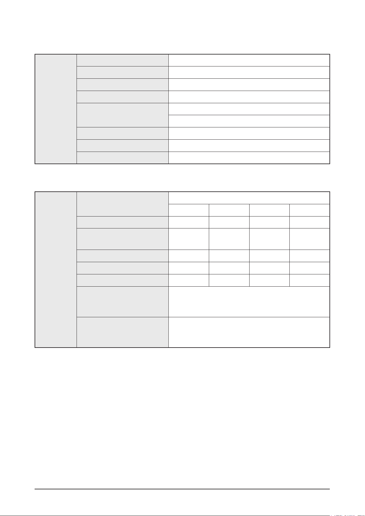
5.1ch Speaker System
Front Surround Center Subwoofer
3Ω 3Ω 3Ω 3Ω
140Hz ~
50KHz
140Hz ~
20KHz
140Hz ~
20KHz
40Hz ~
160Hz
87dB/W/M 87dB/W/M 87dB/W/M 90dB/W/M
165W 165W 170W 170W
330W 330W 340W 340W
Dimensions (W x H x D)
Weights
Front / Surround: 3.96 x 8.27 x 3.90 inches
Center: 11.80 x 2.32 x 1.97 inches
Subwoofer: 7.91 x 15.90 x 16.10 inches
Front / Surround: 1.54 Ibs
Center: 0.73 Ibs
Subwoofer: 11.90 Ibs
Samsung Electronics 2-3
Product Specification
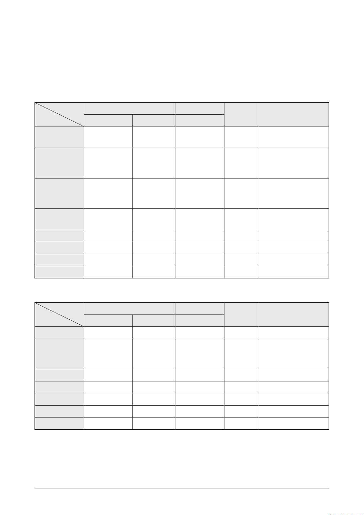
2-2-2 6G BD-HTS Output Resolution
- During CD-DA Play → HPD Off/On → Stop → (Black Screen) → After Changing Resolution → Logo
- During DVD, BD Play → HPD Off/On → (Black Screen) → After Changing Resolution → Play
BD Playback (include CD-DA, Logo)
Output
Setup
BD Wise
Max Resolution
Auto
1080P@60F 1080P@60F 480i Cannot select 480i
1080P@24F 1080P@24F 480i Cannot select 480i
1080i 1080i 480i 1080i 480i
720P 720P 480i 720P 480i
480P 480P 480i 480P 480i
480i Cannot select Cannot select 480i 480i
which TV can
HDMI_HPD On HDMI_HPD Off
HDMI Component Component
Source
Resolution
support
480i Cannot select 480i
480i Cannot select 480i
Output
CVBS
Remark
HDMI 1080p setup →
HPD off →
Component 1080i
HDMI 1080p setup →
HPD off →
Component 1080i
Source is only
1080P@24F
DVD playback
Output
Setup
BD Wise 480i 480i Cannot select 480i
Max Resolution
Auto
1080P@60F 1080P@60F 480i Cannot select 480i
1080i 1080i 480i 480P 480i
720P 720P 480i 480P 480i
480P 480P 480i 480P 480i
480i Cannot select Cannot select 480i 480i
which TV can
HDMI_HPD On HDMI_HPD Off
HDMI Component Component
480i Cannot select 480i
support
CVBS
Output
Remark
2-4 Samsung Electronics
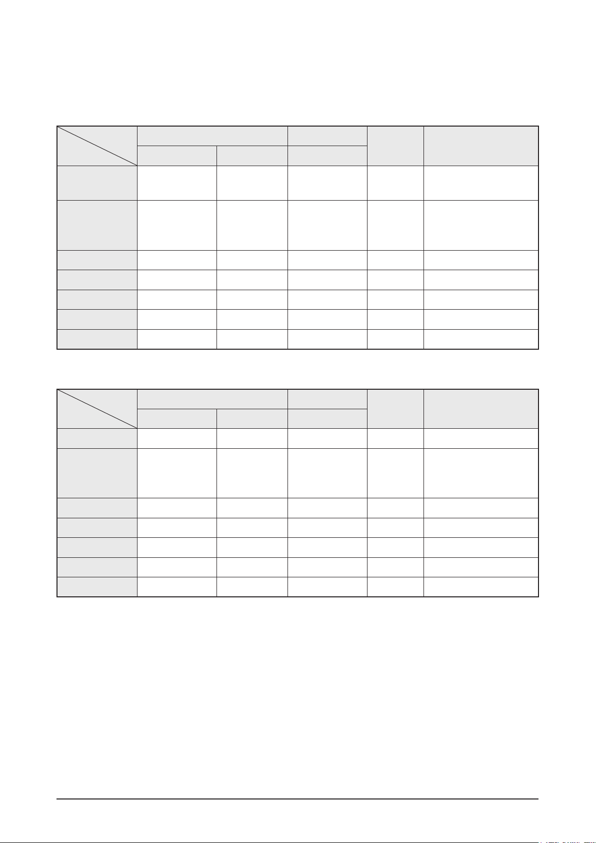
2-2-3 6G BD-HTS PAL Output Resolution
PAL BD-Rom (1080i@50Hz & 720p@50Hz & 576i@25Hz) Playback
Product Specification
Output
Setup
BD Wise
Max Resolution
Auto
1080P@60F 1080p@50F 576i Can select 576i
1080i 1080i@25F 576i 576p 576i
720P 720p@50F 576i 576p 576i
576P/480P 576p@50F 576i 576p 576i
576i/480i Can select Can select 576i 576i
which TV can
HDMI_HPD On HDMI_HPD Off
HDMI Component Component
Source
Resolution
support
576i Can select 576i
576i Can select 576i
PAL DVD Playback
Output
Setup
HDMI_HPD On HDMI_HPD Off
HDMI Component Component
CVBS
Output
CVBS
Output
Remark
Remark
BD Wise 576i 576i Can select 576i
Max Resolution
Auto
1080P@60F 1080p@50F 576i Can select 576i
1080i 1080i@25F 576i 576p 576i
720P 720p@50F 576i 576p 576i
576P/480P 576p@50F 576i 576p 576i
576i/480i Can select Can select 576i 576i
which TV can
support
576i Can select 576i
Samsung Electronics 2-5
Product Specification
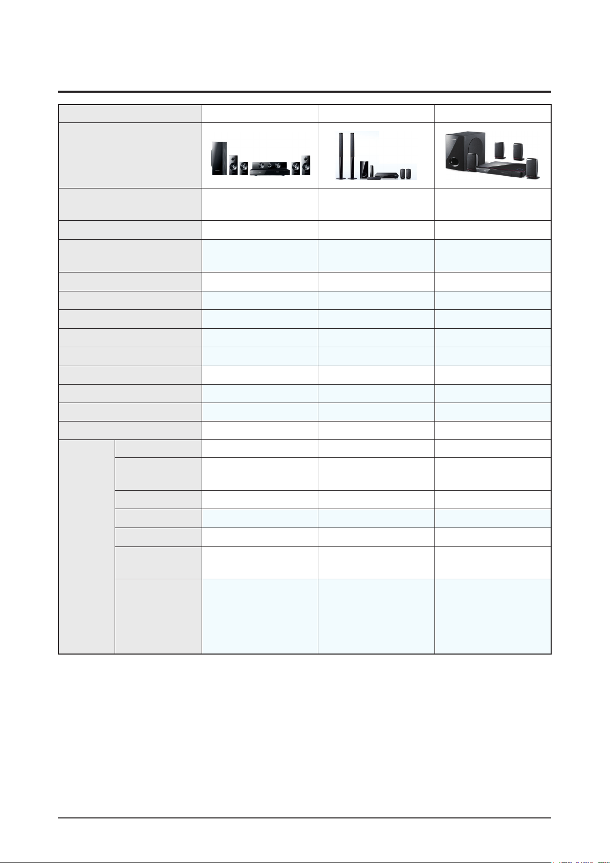
2-3 Specifications Analysis
Model Name HT-C5500 HT-BD3252 HT-BD1250
Photo
Profile
DVD, CD
MP3, JPG
USB HOST
i-POD / i-Phone
Wireless LAN
DivX
Wireless Rear
Memory Slot X (External USB support) X (External USB support) X (External USB support)
DLNA, Widget
Energy-Star
BD-RE support Support 1.0 Support 1.0 Support 1.0
HDMI 1.3 1.3 1.3
1080P/ 24-frame
video
Blu-ray 2.0 from the
beginning
(MP4, HD JPG, MKV,
WMA, WMV)
(only USA)
(Ready) (Bundle included) (Ready)
(DivX-HD support) (DivX-HD support) (only EU / SD support)
(Ready) (Bundle included) (Ready)
0.27W 0.7W 0.7W
Blu-ray 2.0 from the
beginning
X X
Blu-ray 2.0 from the
beginning
HDMI
CEC (Anynet+)
Deep Color
xvYCC
HD Audio
Transmission
Picture Quality
control
(10 bit)
(Progressive Mode,
Still Mode, BD Wise,
Picture Control,
Sharpness, Movie)
X (8bit) X (8bit)
(Progressive Mode,
Still Mode, BD Wise,
Picture Control)
: Feature Included, X: Not Included
(Progressive Mode,
Still Mode, BD Wise,
Picture Control)
2-6 Samsung Electronics
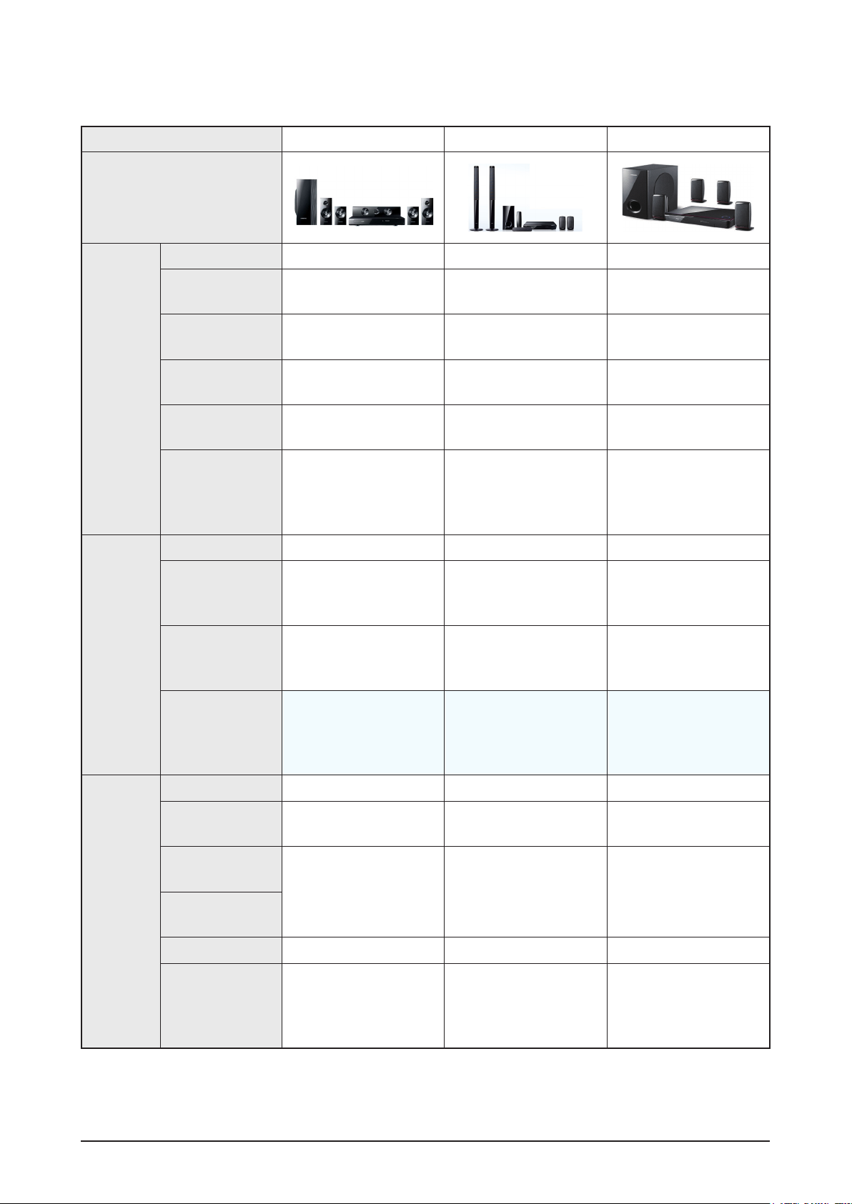
Product Specification
Model Name HT-C5500 HT-BD3252 HT-BD1250
Photo
Video Processor Main SOC Internal Scaler Main SOC Internal Scaler Main SOC Internal Scaler
Video
Video
1080P/ 60-frame
video
1080i/ 60-frame
video
1080P/ 24-frame
video
480i/p video
output for Blu-ray
Simultaneous
Video Output
between HDMI/
Component/CVBS
Factory Default 480p 480p 480p
When connected
to a TV with
correct EDID
When conncted
to a TV with an
incorrect EDID
Maximum resolution for
Maximum resolution for
TV input
480p 480p 480p
TV input
Maximum resolution for
TV input
Audio
Remark
DD Plus decoding
Dolby TrueHD
decoding
DTS HD HRA
decoding
DTS-HD MA
decoding
Re-encoding
HD audio bit
stream output on
HDMI 1.3
HT-C5500 can also output
480i/480p resolution with
Blu-ray Disc
(DTS-HD Master Audio
essential)
(intoDTS) (into DTS) (into DTS)
DTS-HD MA Essential
dts-HD HRA
TrueHD
DD+
HT-BD3250 can also
output 480i/480p
resolution with Blu-ray
Disc
(DTS-HD Master Audio
essential)
DTS-HD MA Essential
dts-HD HRA
TrueHD
DD+
HT-BD1250 can also
resolution with Blu-ray
(DTS-HD Master Audio
DTS-HD MA Essential
: Feature Included, X: Not Included
output 480i/480p
Disc
essential)
dts-HD HRA
TrueHD
DD+
Samsung Electronics 2-7
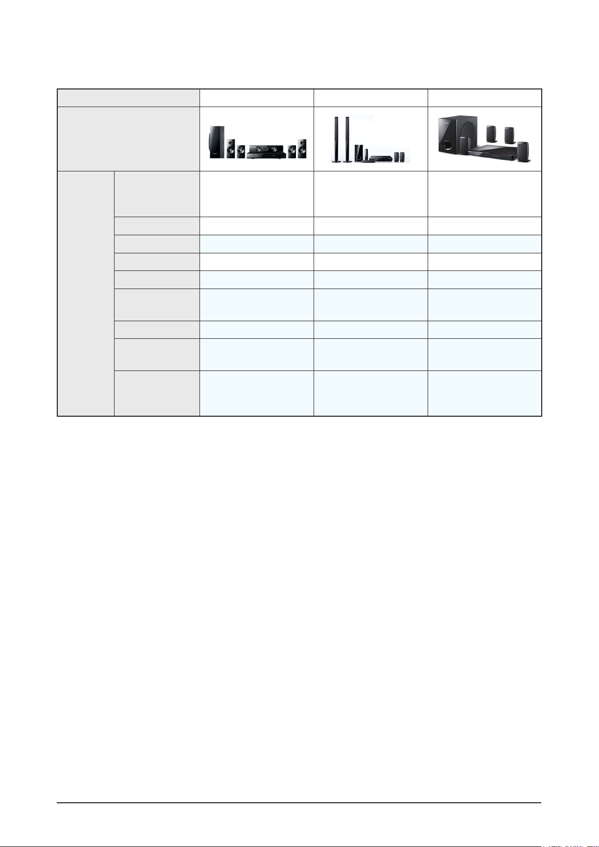
Product Specification
Model Name HT-C5500 HT-BD3252 HT-BD1250
Photo
H/W
2 trans
SMPS
Deck Draw type Plastic Cover Draw type Plastic Cover Draw type Plastic Cover
Pick Up 6G VE Pickup 5G VE Pickup 5G VE Pickup
Front Micom SANYO SANYO SANYO
MAIN CHIP BCM7630 BCM7601 BCM7440
Wireless Rear
Speaker
WiFi Lan Dongle Ready Included Ready
HDMI IN
Main↔Loader
Stand-By Power
Consumption 0.7W
Ready (SWA-5000) Included (SWA-4100) Ready (SWA-5100)
X (Except USA, all support
2 Input)
One Board
(BCM 7630 - Back end,
SoC chip - Front end)
(BCM 7601 - Back end,
2 trans
Stand-By Power
Consumption 0.7W
2 Inputs support X
One Board
BCM7620 - Front end)
Stand-By Power
Consumption 0.7W
(BCM 7440 - Back end,
BCM7620 - Front end)
2 trans
One Board
: Feature Included, X: Not IncludedFeature Included, X: Not Included
2-8 Samsung Electronics
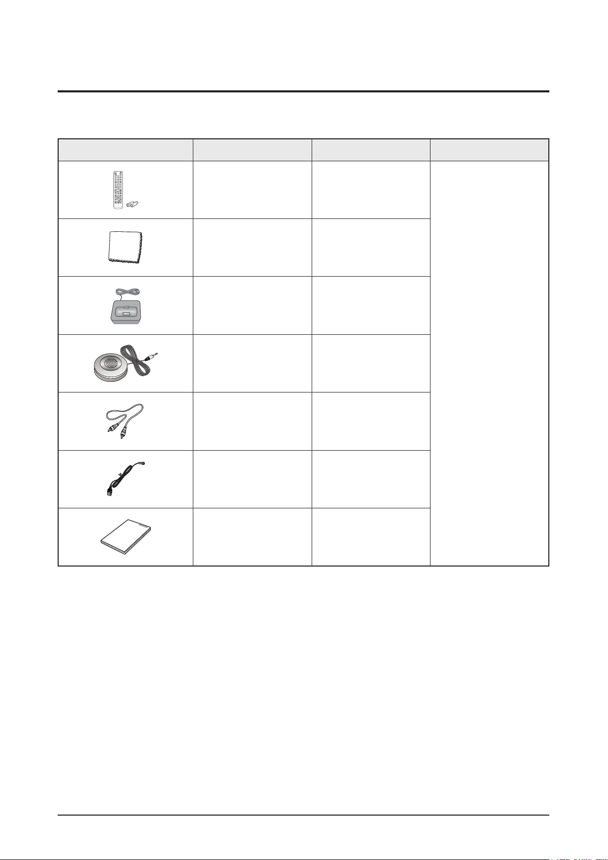
2-4 Accessories
2-4-1 Supplied Accessories
Accessories Item Item code Remark
Product Specification
Remote Control
Battery
Cloth Clean AH81-02286C
iPod Dock AH96-00051A
ASC Microphone AH30-00099A
Audio Cable AH39-40001V
AH59-02298A
4301-000121
Local Samsung Dealer
FM Antenna AH42-00021A
User’s Manual AH68-02258L
Samsung Electronics 2-9

MEMO
2-10 Samsung Electronics
Disassembly & Reassembly
3. Disassembly & Reassembly
3-1 Overall Disassembly & Reassembly
- Be careful to follow the disassembly sequence described in the manual. Otherwise, the product
may be damaged.
- Be sure to carefully read and understand the safety instructions before performing any work as
the IC chips on the PCB are vulnerable to static electricity.
- In order to assemble reverse the order of disassembly.
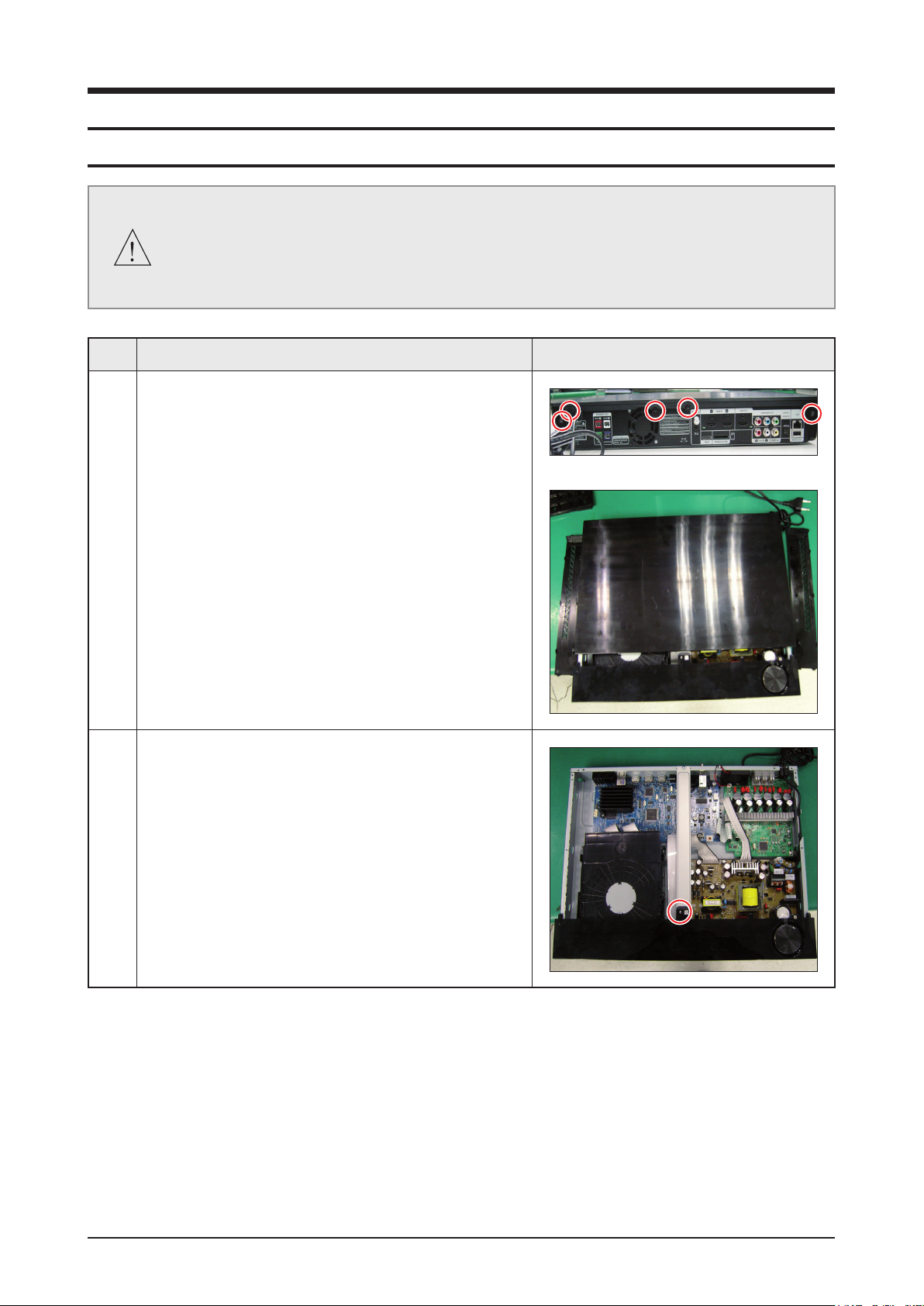
No. Description Description Photo
1 1) Unfasten 5 screws on the DECO-SIDE.
2) Remove DECO-SIDE & TOP on the direction of Rear.
2 1) Unfasten 1 screw to remove CABINET-FRONT.
Samsung Electronics 3-1
Disassembly & Reassembly
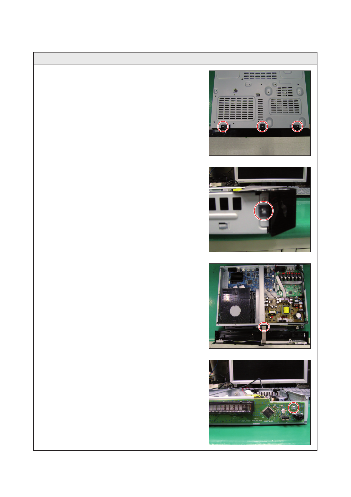
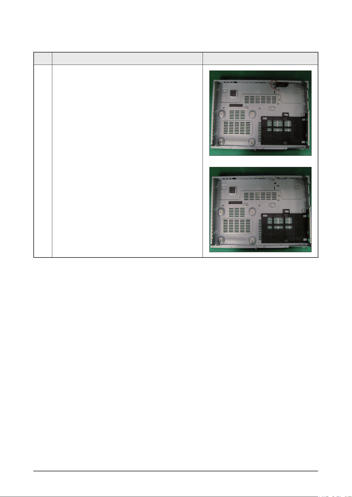
No. Description Description Photo
2 2) Loosen hooks from CABINET-BOTTOM.
3) Disconnect wire, then remove the
CABINET-BOTTOM.
3 1) Unfasten 1 screw, then remove ASSY PCB FRONT.
3-2 Samsung Electronics
Disassembly & Reassembly
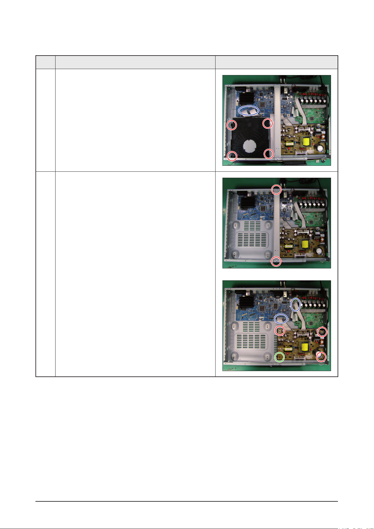
No. Description Description Photo
4 1) Unfasten 4 screws, disconnect FPC wire, and remove
ASSY-DECK.
5 1) Unfasten 2 screws, then remove BRACKET-TOP.
2) Unfasten 3 screws, loosen 1 hook, and disconnect
2 wires and remove ASSY-SMPS and POWER-
CORD.
Samsung Electronics 3-3
Disassembly & Reassembly
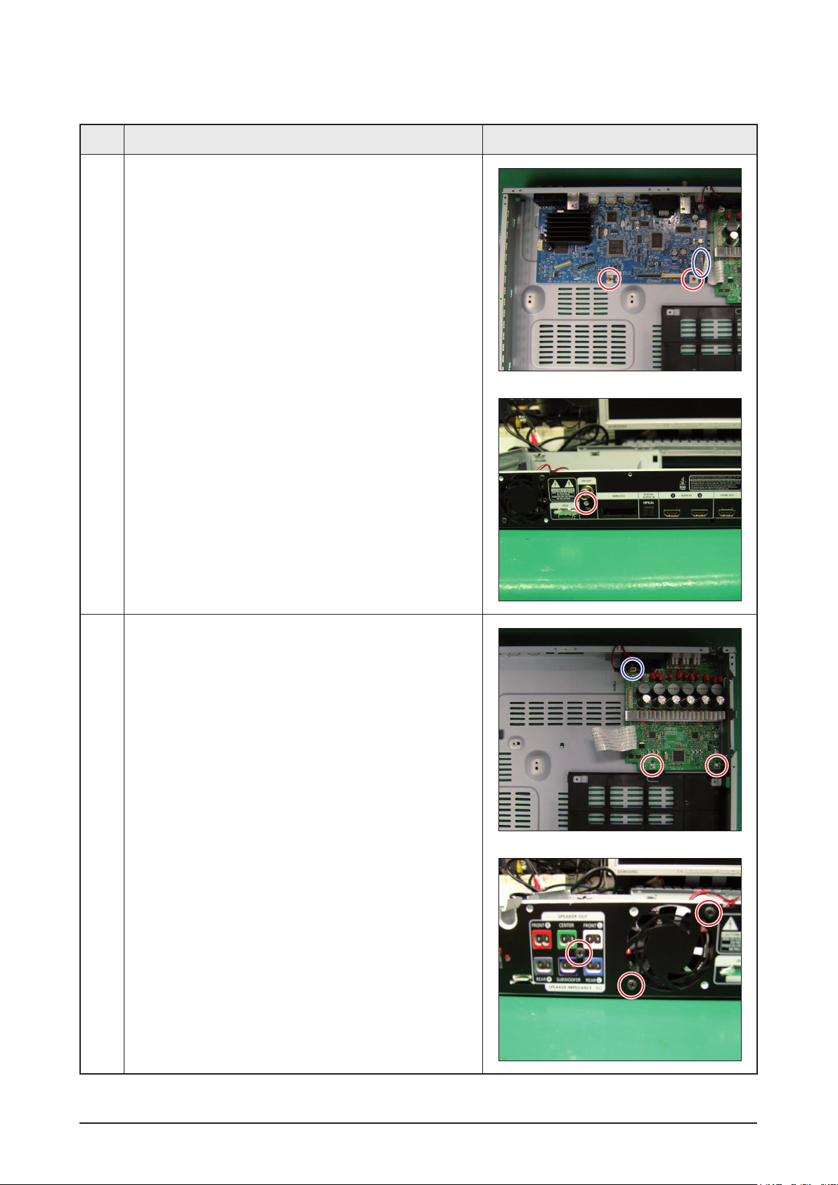
No. Description Description Photo
6 1) Unfasten 2 screws and 1 wire, then remove
ASSY PCB MAIN.
7 1) Unfasten 5 screws to remove AMP and FAN.
3-4 Samsung Electronics
Disassembly & Reassembly
No. Description Description Photo
8 1) Remove ASSY PCB AMP and FAN.
Samsung Electronics 3-5
Disassembly & Reassembly
3-2 DECK Disassembly & Reassembly
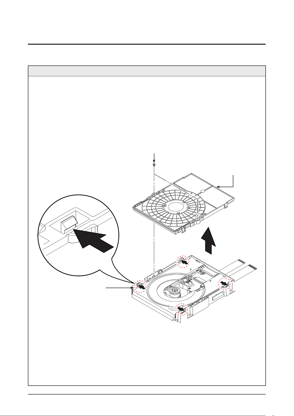
3-2-1 Ass’y Cover Removal
Description
1. Remove 2 Screws
1.
2. Push 4 Hooks 2 in the Direction of Arrow “A”.
3. Lift up the Ass’y Cover 3 in direction of arrow “B”.
1 2 SCREWS
(M 2 X 7 W)
3 ASS'Y COVER
2 4 HOOKS
“A”
“A”
“A”
“A”
3-6 Samsung Electronics
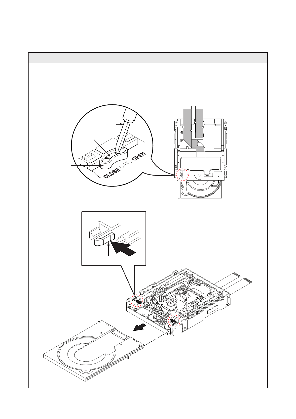
3-2-2 Tray Disc Removal
Disassembly & Reassembly
Description
1. Insert a Screw Driver into Hole
1 and rotate Gear Tray 2 in the direction arrow “Open”.
2. When the Tray Disc 3 comes out a little, pull in the direction of arrow “A” using your hand.
3. Pull the Tray Disc 3 to disassemble, while simultaneously pushing 2 Stoppers 4 (left, right) in the
direction arrow “B”, “C”.
SCREW DRIVER
2 GEAR TRAY
1 HOLE
(BOTTOM VIEW)
4 STOPPER
“B”
“A”
“C”
3 TRAY DISC
(TOP VIEW)
Samsung Electronics 3-7
Disassembly & Reassembly
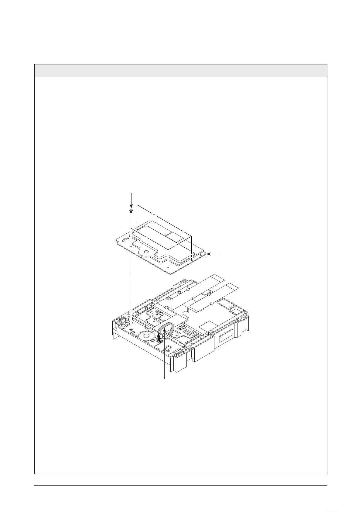
3-2-3 Cover Bottom Removal (Optional)
Description
1. Remove 4 Screws
1.
2. Lift up the Cover Bottom 2.
3. Remove FFC Cable 3.
1 4 SCREWS
(M 1.7 X 5 W)
2 COVER BOTTOM
3 FFC CABLE
3-8 Samsung Electronics
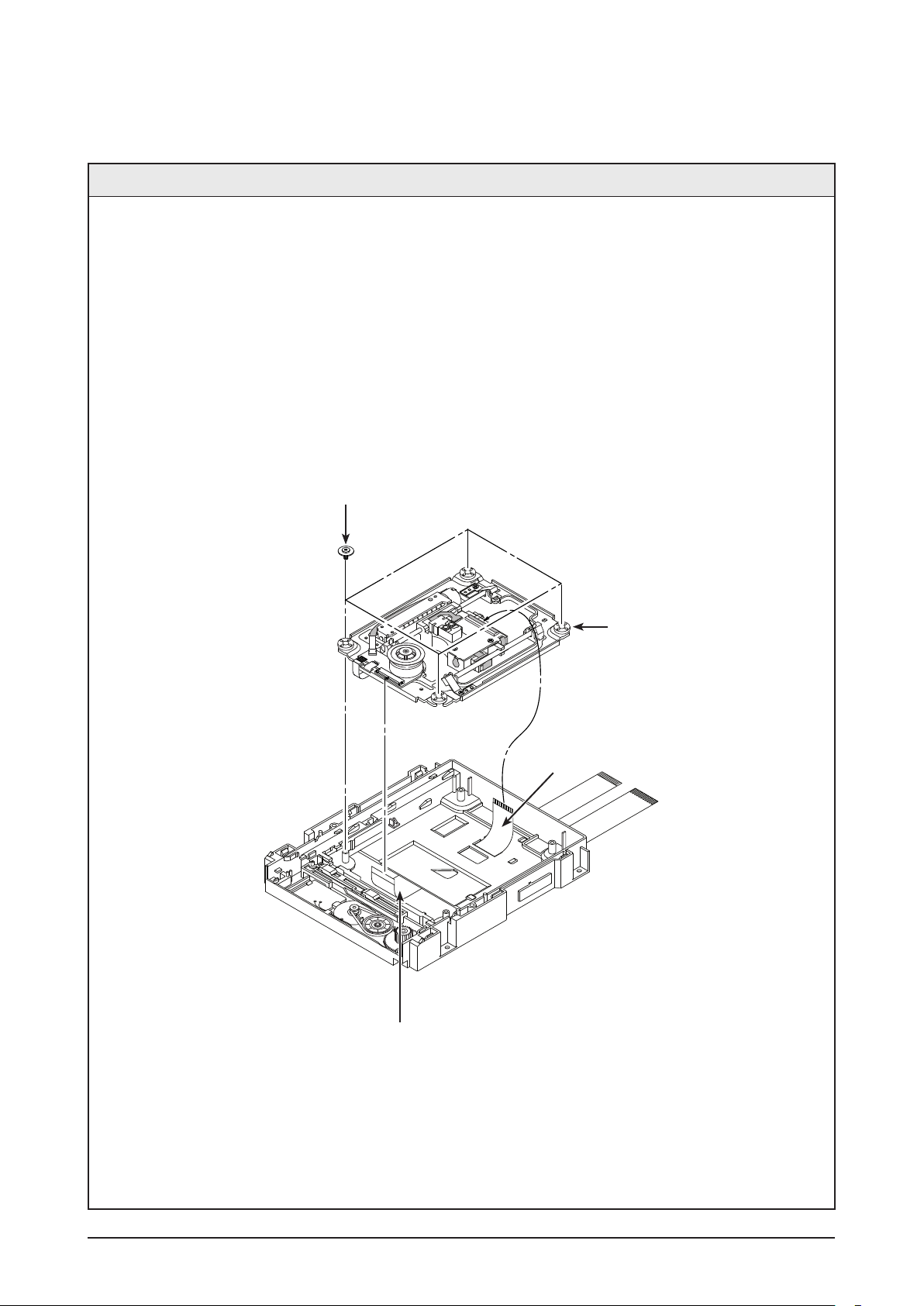
3-2-4 Assy Traverse Deck Removal
Disassembly & Reassembly
Description
1. Remove FFC PU Cable
1.
2. Removal 4 Screws 2.
3. Lift up the Assy Traverse Deck 3.
4. Remove FFC Deck Cable 4.
2 4 SCREWS
(M 2.6 X 6 B)
3 ASS’Y TRAVERSE DECK
4 FFC DECK
1 FFC PU
Samsung Electronics 3-9
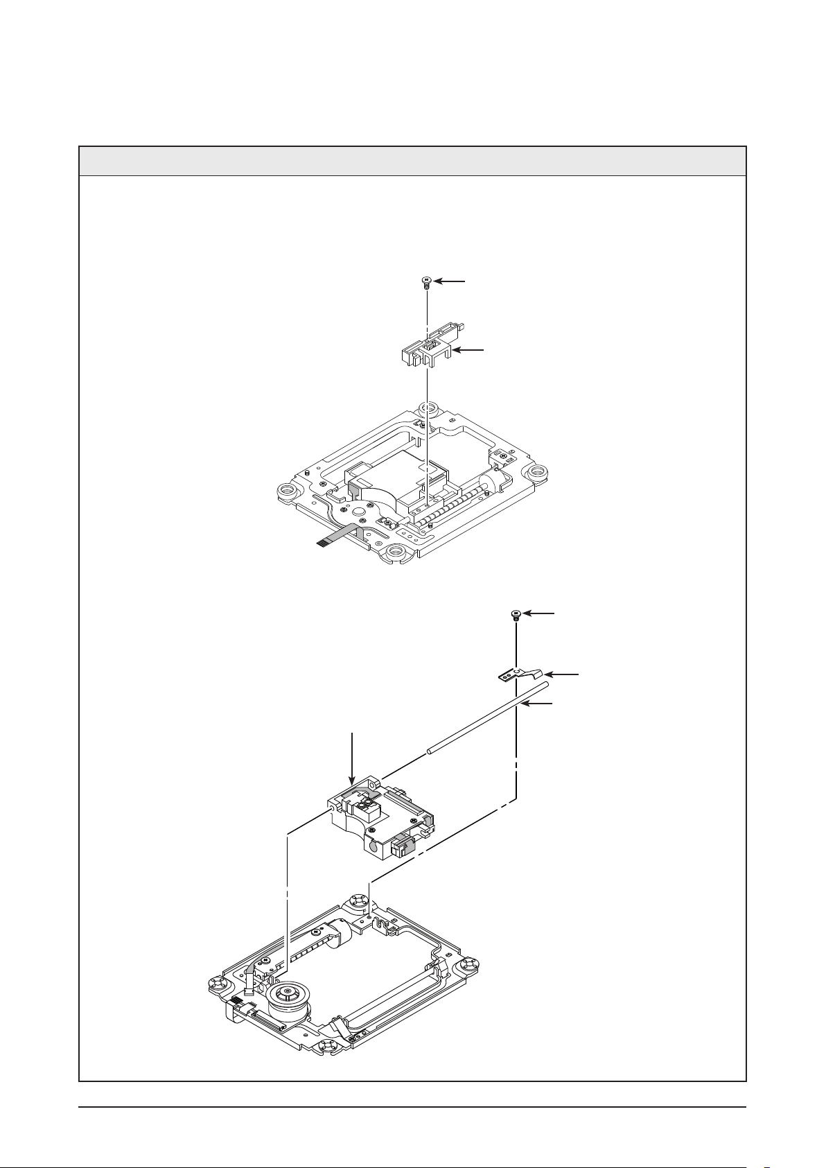
Disassembly & Reassembly
3-2-5 Ass’y Pick Up Removal
Description
1. Remove 1 Screw
1 and Lift up the Assy Hinge PU 2.
2. Remove 1 Screw 3 and Lift up Brkt Shaft Fix R 4.
3. Lift Up Shaft P/U 5 and Remove the Ass’y Pick Up 6.
(BOTTOM VIEW)
1 1 SCREW
(M 1.7 X 5 W)
2 ASS'Y HINGE PU
6 ASS'Y PICK UP
3 1 SCREW
(M 1.7 X 5 W)
4 BRKT SHAFT FIX R
5 SHAFT P/U
(TOP VIEW)
3-10 Samsung Electronics
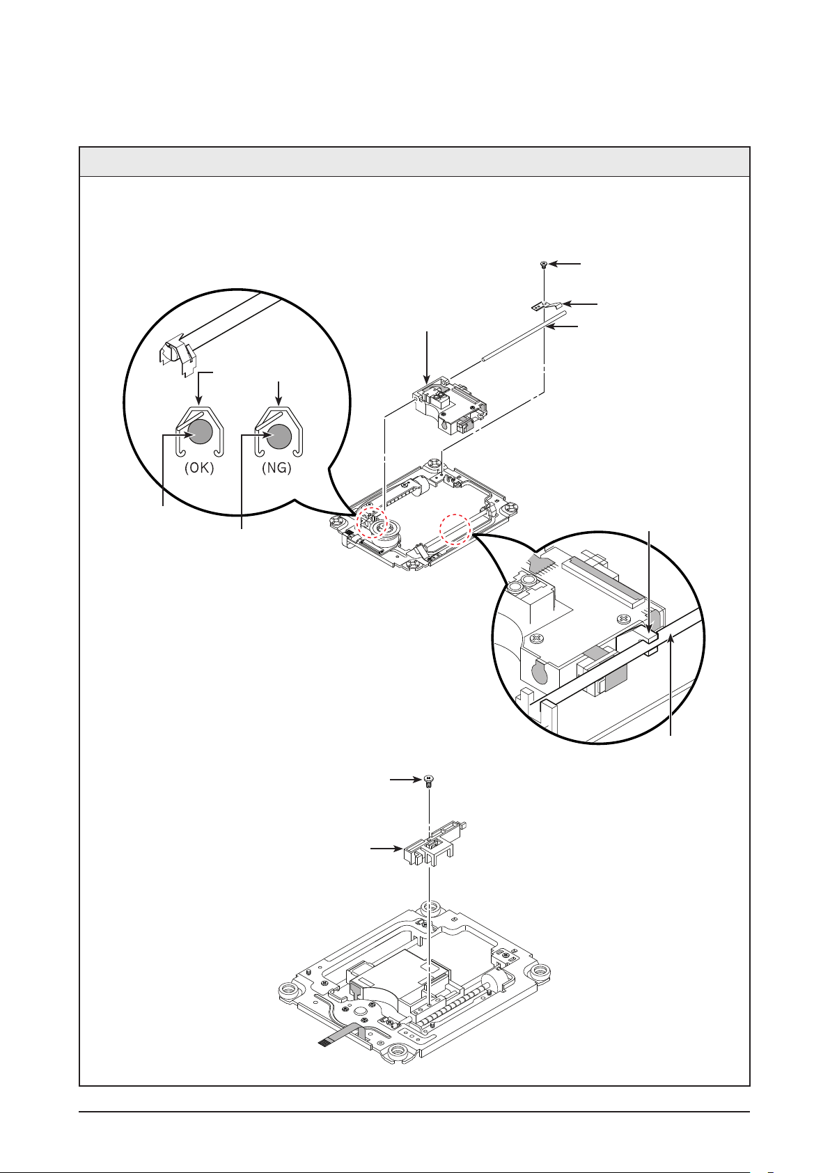
3-2-6 Ass’y Pick Up Assemble
Disassembly & Reassembly
Description
1. Insert the Shaft P/U
1 into the Ass’y pick up 2.
2. Insert the Brkt Shaft Fix R 3 Assemble 1 Screw 4.
3. Insert the Ass’y Hinge PU 5 Assemble 1 Screw 6.
2 ASS'Y PICK UP
BRACKET SHAFT PU
SHAFT P/U
SHAFT P/U
4 1 SCREW
(M 1.7 X 5 W)
3 BRKT SHAFT FIX R
1 SHAFT P/U
ASS'Y PICK UP
SHAFT P/U
6 1 SCREW
(M 1.7 X 5 W)
5 ASS'Y HINGE PU
Samsung Electronics 3-11

MEMO
3-12 Samsung Electronics
 Loading...