

Page 1
2.1CH Blu-ray
Home Theater System
Model Name : HT-C5200
Model Code : HT-C5200/EDC
Speaker PS-C5200
Front PS-FC5200
Subwoofer PS-WC5200
SERVICE
Manual
2.1CH Blu-ray Home Theater System
HT-C5200
CONTENTS
1. Precaution
2. Product Specification
3. Disassembly & Reassembly
4. Troubleshooting
5. Exploded View & Part List
6. PCB Diagram
7. Schematic Diagram
Refer to the service manual in the GSPN (see the rear cover) for the more information.
Page 2
GSPN (Global Service Partner Network)
Area Web Site
North America service.samsungportal.com
Latin America latin.samsungportal.com
CIS cis.samsungportal.com
Europe europe.samsungportal.com
China china.samsungportal.com
Asia asia.samsungportal.com
Mideast & Africa mea.samsungportal.com
This Service Manual is a property of Samsung Electronics
Co.,Ltd. Any unauthorized use of Manual can be punished
under applicable International and/or domestic law.
© Samsung Electronics Co.,Ltd.
Printed in Korea
Apr. 2010
Page 3

Contents
1. Precaution
1-1 Safety Precautions ...........................................................................................1-1
1-2 Servicing Precautions ......................................................................................
1-3 Precautions for Electrostatically Sensitive Devices (ESDs) .............................
2. Product Specification
2-1 Product Feature ...............................................................................................2-1
2-2 Specifications ...................................................................................................
2-3 Specifications Analysis .....................................................................................
2-4 Accessories ......................................................................................................
3. Disassembly & Reassembly
3-1 Overall Disassembly & Reassembly ................................................................3-1
3-2 DECK Disassembly & Reassembly
1-3
1-4
2-2
2-6
2-9
..................................................................3-6
4. Troubleshooting
4-1 Checkpoints by Error Mode.............................................................................. 4-1
4-2 Initialization & Upgrade Methods .....................................................................
4-3 Buyer-Region Code Setting Method ................................................................
5. Exploded View & Part List
5-1 Product Exploded View ....................................................................................5-1
5-2 DECK Exploded View ......................................................................................
5-3 Speaker System ...............................................................................................
5-4 Electrical Part List ............................................................................................
6. PCB Diagram
6-1 Wiring Diagram ................................................................................................6-1
6-2 FRONT PCB Top ..............................................................................................
6-3 KEY PCB Top ...................................................................................................
6-4 AMP PCB Top ..................................................................................................
6-5 AMP PCB Bottom .............................................................................................
6-6 MAIN PCB Top .................................................................................................
6-7 MAIN PCB Bottom ...........................................................................................
6-8 SMPS PCB Top ................................................................................................
6-9 SMPS PCB Bottom ..........................................................................................
4-24
4-27
5-3
5-5
5-6
6-2
6-4
6-6
6-8
6-9
6-12
6-14
6-16
Page 4

Contents
7. Schematic Diagram
7-1 Overall Block Diagram .....................................................................................7-1
7-2 FRONT .............................................................................................................
7-3 KEY ..................................................................................................................
7-4 AMP-1 ..............................................................................................................
7-5 AMP-2 ..............................................................................................................
7-6 AMP-3 ..............................................................................................................
7-7 AMP-4 ..............................................................................................................
7-8 ETHERNET / USB / WI-FI ................................................................................
7-9 VIDEO / IPOD VIDEO ......................................................................................
7-10 HDMI MICOM
7-11 HDMI RX ..........................................................................................................
7-12 HDMI TX ..........................................................................................................
7-13 NAND FLASH / CLOCK / BBS / JTAG .............................................................
7-14 DDR3-1333 ......................................................................................................
7-15 GPIO / BOOT STRAP / UART / RX_SW ..........................................................
7-16 7630 POWER / DECOUPLING ........................................................................
7-17 F/E OPU CONNECTION
7-18 F/E MOTOR DRIVE .........................................................................................
7-19 FRONT MICOM ...............................................................................................
7-20 DIR / ADC / RX SWITCHING / D.IN .................................................................
7-21 DSP SDRAM / FLASH .....................................................................................
7-22 DC-DC POWER ...............................................................................................
7-23 IPOD ................................................................................................................
7-24 SMPS ...............................................................................................................
7-2
7-3
7-4
7-5
7-6
7-7
7-8
7-9
...................................................................................................7-10
7-11
7-12
7-13
7-14
7-15
7-16
..................................................................................7-17
7-18
7-19
7-20
7-21
7-22
7-23
7-24
Page 5
Precaution
1. Precaution
Follow these safety instructions while servicing the ESD to prevent damage and to protect against potential
hazards such as electrical shock and X-rays.
1-1 Safety Precautions
1. When reinstalling the chassis and its assemblies, be sure to restore all of the protective devices, including the
control knobs and the compartment covers.
2. Make sure that there are no cabinet openings through which people (particularly children) can make contact
with dangerous internal components.
3. Design Alteration Warning:
Never alter or add to the mechanical or electrical design of the unit.
Example: Do not add auxiliary audio or video connectors. Such alterations might create a safety hazard.
Also, any design changes or additions will void the manufacturer’s warranty.
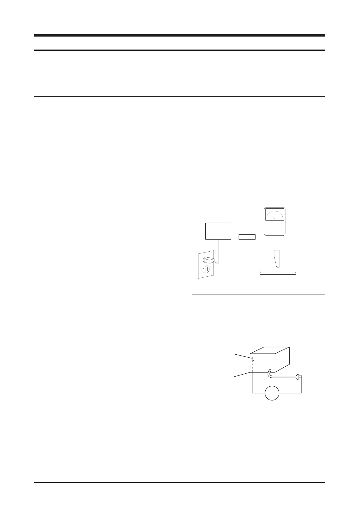
4. Leakage Current Hot Check (Fig. 1-1):
Warning: Do not use an isolation transformer during this
test. Use a leakage-current tester or a metering system
that complies with American National Standards Institute
(ANSI C101.1, Leakage Current for Appliances), and
Underwriters Laboratories (UL Publication UL1410,
59.7).
With the unit completely reassembled, plug the AC cord
directly into a 120V AC outlet. With the unit’s power
switched from the ON to the OFF position, measure the
current between a known ground and all exposed metal
DEVICE
UNDER
TEST
TEST ALL
EXPOSED METAL
SURFACES
2-WIRE CORD
ALSO TEST WITH
PLUG REVERSED
(USING AC
ADAPTER PLUG
AS REQUIRED)
<Fig. 1-1 AC Leakage Test>
LEAKAGE
CURRENT
TESTER
(READING
SHOULD NOT BE
ABOVE 0.5mA)
parts.
Known Grounds - Earth
Known Metal parts - screwheads, metal cabinets, etc.
EARTH
GROUND
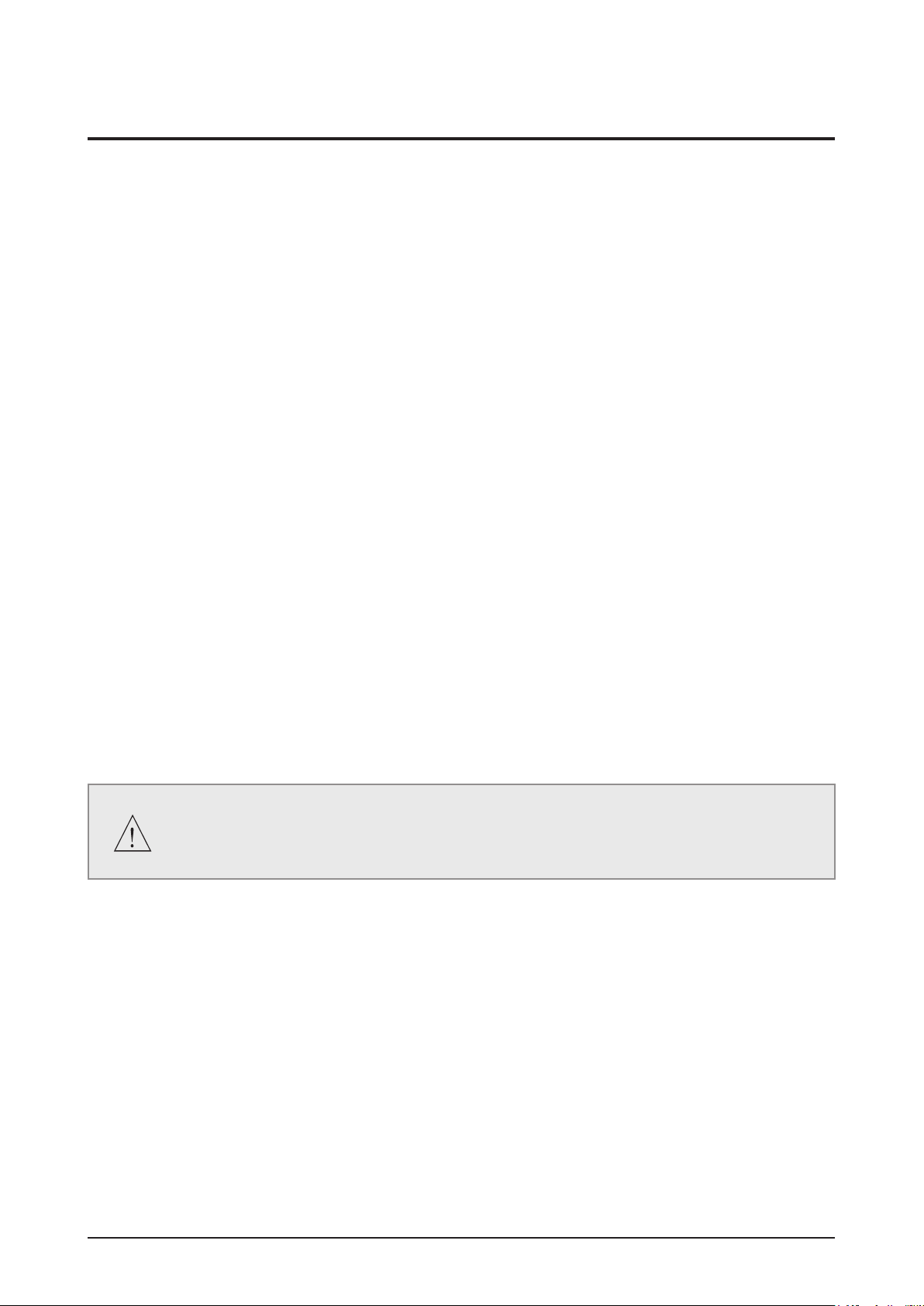
5. Insulation Resistance Cold Check:
(1) With the unit’s AC plug disconnected from the AC
source, connect an electrical jumper across the two AC
Antenna
Terminal
prongs. (2) Set the power switch to ON. (3) Measure
the resistance between the shorted AC plug and any
Exposed
Metal Part
exposed metallic parts.
Example: screwheads, metal cabinets, antenna port
If any of the exposed metallic parts has a return path
<Fig. 1-2 Insulation Resistance Test>
ohm
Ohmmeter
to the chassis, the measured resistance should be
between 1 and 5.2 megohms. If there is no return path,
the measured resistance should be “infinite.” If the resistance is outside these limits, a shock hazard might
exist. See Fig. 1-2
Samsung Electronics 1-1
Page 6

1-2 Samsung Electronics
Precaution
6. Components, parts and wiring that appear to have overheated or that are otherwise damaged should be
replaced with parts that meet the original specifications. Always determine the cause of damage or overheating,
and correct any potential hazards
7. Observe the original lead dress, especially near the following areas: Antenna wiring, sharp edges, and
especially the AC and high voltage power supplies. Always inspect for pinched, out-of-place, or frayed wiring.
Do not change the spacing between components and the printed circuit board. Check the AC power cord for
damage. Make sure that no wires or components touch thermally hot parts.
8. Product Safety Notice:
Some electrical and mechanical parts have special safety-related characteristics which might not be obvious
from visual inspection. These safety features and the protection they give might be lost if the replacement
component differs from the original--even if the replacement is rated for higher voltage, wattage, etc.
9. Components that are critical for safety are indicated in the circuit diagram by shading,
or . Use
replacement components that have the same ratings, especially for flame resistance and dielectric strength
specifications. A replacement part that does not have the same safety characteristics as the original might
create shock, fire or other hazards.
Page 7
Precaution
1-2 Servicing Precautions
1. Servicing precautions are printed on the cabinet. Follow them.
2. Always unplug the unit’s AC power cord from the AC power source before attempting to: (a) Remove or reinstall
any component or assembly, (b) Disconnect an electrical plug or connector, (c) Connect a test component in
parallel with an electrolytic capacitor.
3. Some components are raised above the printed circuit board for safety. An insulation tube or tape is sometimes
used. The internal wiring may be clamped to prevent contact with thermally hot components. Reinstall all such
elements to their original position.
4. After servicing, always check that the screws, components and wiring have been correctly reinstalled.
Make sure that the portion around the serviced part has not been damaged.
5. Check the insulation between the blades of the AC plug and accessible conductive parts (examples: metal
panels, input terminals and earphone jacks).
6. Insulation Checking Procedure: Disconnect the power cord from the AC source. Connect an insulation
resistance meter (500V) to the blades of the AC plug.
The insulation resistance between each blade of the AC plug and accessible conductive parts (see above)
should be greater than 1 megohm.
7. Never defeat any of the B+ voltage interlocks. Do not apply AC power to the unit (or any of its assemblies)
unless all solid-state heat sinks are correctly installed.
8. Always connect a test instrument’s ground lead to the instrument chassis ground before connecting the positive
lead; always remove the instrument’s ground lead last.
First read the “Safety Precautions” section of this manual. If some unforeseen circumstance
creates a conflict between the servicing and safety precautions, always follow the safety
precautions.
Samsung Electronics 1-3
Page 8

Precaution
1-3 Precautions for Electrostatically Sensitive Devices (ESDs)
Some semiconductor (“solid state”) devices are easily damaged by static electricity.
Such components are called Electrostatically Sensitive Devices (ESDs).
Examples include integrated circuits and some field-effect transistors. The following techniques will reduce the
occurrence of component damage caused by static electricity:
1. Immediately before handling any semiconductor components or assemblies, drain the electrostatic charge from
your body by touching a known earth ground. Alternatively, wear a discharging wrist-strap device. (Be sure to
remove it prior to applying power--this is an electric shock precaution.)
2. After removing an ESD-equipped assembly, place it on a conductive surface such as aluminum foil to prevent
accumulation of electrostatic charge.
3. Do not use freon-propelled chemicals. These can generate electrical charges that damage ESDs.
4. Use only a grounded-tip soldering iron when soldering or unsoldering ESDs.
5. Use only an anti-static solder removal device. Many solder removal devices are not rated as “anti-static” (these
can accumulate sufficient electrical charge to damage ESDs).
6. Do not remove a replacement ESD from its protective package until you are ready to install it.
Most replacement ESDs are packaged with leads that are electrically shorted together by conductive foam,
aluminum foil or other conductive materials.
7. Immediately before removing the protective material from the leads of a replacement ESD, touch the protective
material to the chassis or circuit assembly into which the device will be installed.
8. Minimize body motions when handling unpackaged replacement ESDs. Motions such as brushing clothes
together, or lifting a foot from a carpeted floor can generate enough static electricity to damage an ESD.
1-4 Samsung Electronics
Page 9

2. Product Specification
2-1 Product Feature
Features for HT-C5200
- BD-LIVE
- DTS-HD Master Audio decoding from the beginning of the Mass Production
- MP3, HD JPG, DivX-HD, MKV, MP4, WMA, WMV
- Blockbuster, Netflix, Pandora,Youtube, Widget
- 2 USB port (Not only on rear, but also on front)
- i-POD Docking, supporting i-POD/iPod
- Various Video Setups
• Progressive Mode
• Still Mode
• BD Wise
• Picture Control
HT-BD1250→HT-C5200
- DLNA, WIDGET
- MKV, MP4
- Under 0.3W Stand-by Power Consumption Energy-Star.
- Variable Power / Intelligence Power
Product Specification
Samsung Electronics 2-1
Page 10
Product Specification
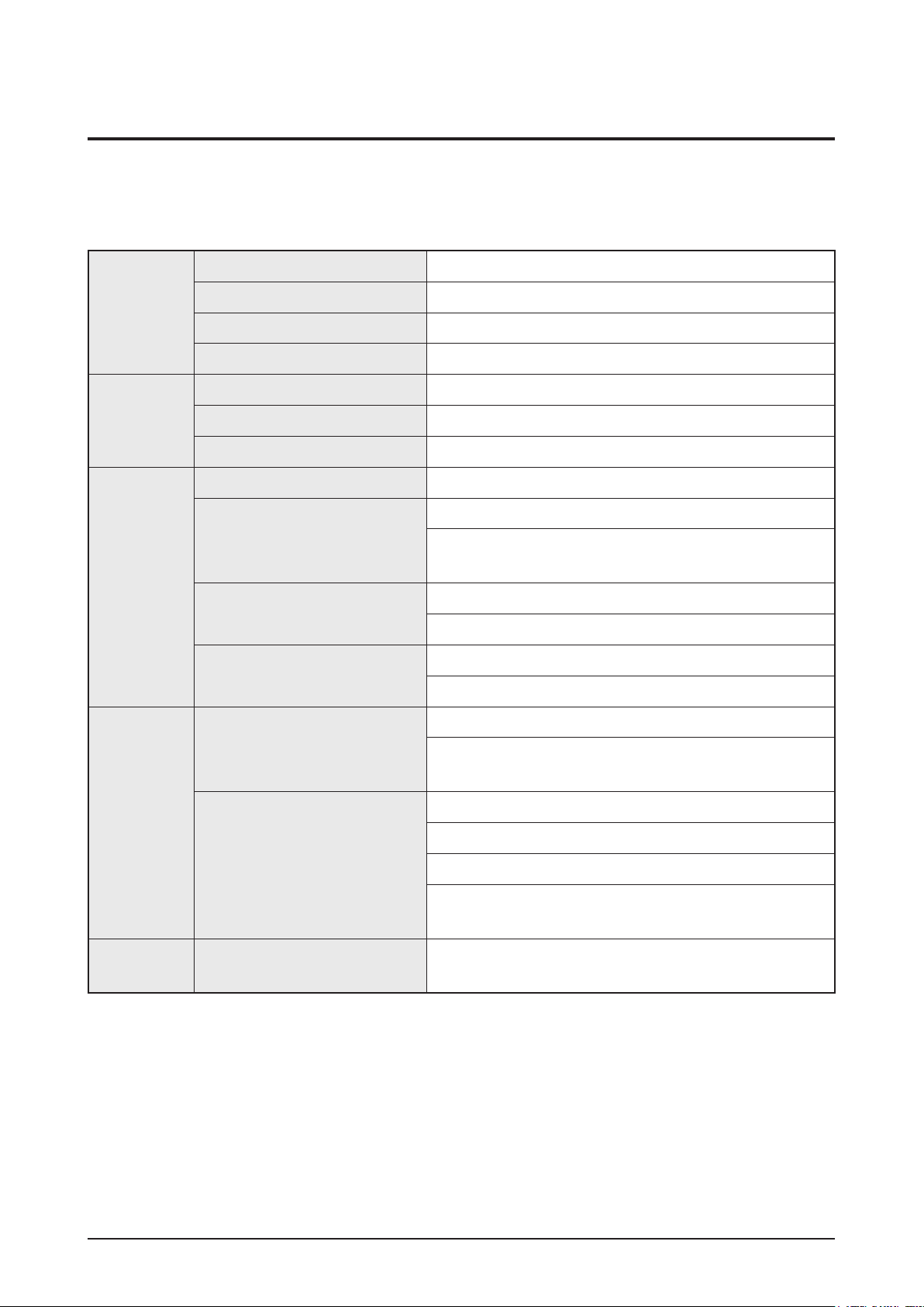
2-2 Specifications
2-2-1
Specications
Basic Specification
Weight 3.5 kg
GENERAL
FM Tuner
DISC
Dimensions 430 (W) x 63 (H) x 325 (D) mm
Operating Temperature Range
Operating Humidity Range
Signal/noise ratio
Usable sensitivity
Total harmonic distortion
BD (Blu-ray Disc)
DVD (Digital Versatile Disc)
CD: 12 cm
(COMPACT DISC)
+5°C to +35°F
10% to 75%
70 dB
10 dB
0.5 %
Reading Speed: 4.917m/sec
Reading Speed: 3.49 ~ 4.06 m/sec.
Approx. Play Time (Single Sided, Single Layer Disc):
135 min.
Reading Speed: 4.8 ~ 5.6 m/sec.
Maximum Play Time: 74 min.
VIDEO
OUTPUT
VIDEO/
AUDIO
CD: 8 cm
(COMPACT DISC)
Composite Video
Component Video
HDMI
Reading Speed: 4.8 ~ 5.6 m/sec.
Maximum Play Time: 20 min.
1 channel: 1.0 Vp-p (75Ω load)
Blu-ray Disc: 576i (480i)
DVD: 576i (480i)
Y: 1.0 Vp-p (75Ω load)
Pr: 0.70 Vp-p (75Ω load)
Pb: 0.70 Vp-p (75Ω load)
Blu-ray Disc: 1080i, 720p, 576p(480p), 576i(480i)
DVD: 576p(480p), 576i(480i)
1080p, 1080i, 720p, 576p(480p)
PCM multichannel audio, Bitstream audio, PCM audio
2-2 Samsung Electronics
Page 11
Product Specification
Front speaker output
Center speaker output
Frequency range
AMPLIFIER
S/N Ratio
Channel separation
Input sensitivity
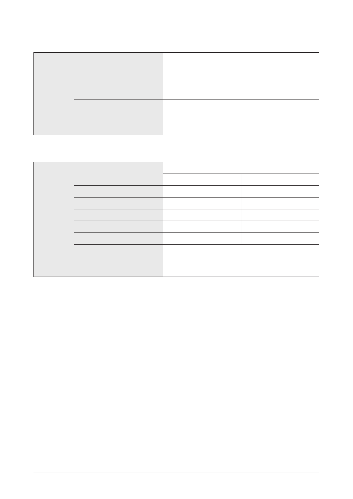
Speaker Specification
Speaker system
Impedance
Frequency range
SPEAKER
Output sound pressure level
Rated input
165W x 2 (3Ω)
170W (3Ω)
Analog input: 20Hz ~ 20kHz (±3dB)
Digital input: 20Hz ~ 44kHz (±3dB)
70dB
60dB
(AUX) 500mV
2.1ch Speaker System
Front Subwoofer
3Ω 3Ω
140Hz ~ 20KHz 40Hz ~ 160Hz
87dB/W/M 88dB/W/M
165W 170W
Maximum input
Dimensions (W x H x D)
Weights
330W 340W
Front: 90 x 207.5 x 68.5 mm
Subwoofer: 168 x 350 x 295 mm
Front: 0.67 kg, Subwoofer: 3.80 kg
Samsung Electronics 2-3
Page 12
Product Specification
2-2-2 6G BD-HTS Output Resolution
- During CD-DA Play → HPD Off/On → Stop → (Black Screen) → After Changing Resolution → Logo
- During DVD, BD Play → HPD Off/On → (Black Screen) → After Changing Resolution → Play
BD Playback (include CD-DA, Logo)
Output
Setup
BD Wise
Max Resolution
Auto
1080P@60F 1080P@60F 480i Cannot select 480i
1080P@24F 1080P@24F 480i Cannot select 480i
1080i 1080i 480i 1080i 480i
720P 720P 480i 720P 480i
480P 480P 480i 480P 480i
480i Cannot select Cannot select 480i 480i
which TV can
HDMI_HPD On HDMI_HPD Off
HDMI Component Component
Source
Resolution
support
480i Cannot select 480i
480i Cannot select 480i
CVBS
Output
Remark
HDMI 1080p setup →
HPD off →
Component 1080i
HDMI 1080p setup →
HPD off →
Component 1080i
Source is only
1080P@24F
DVD playback
Output
Setup
BD Wise
Max Resolution
Auto
1080P@60F 1080P@60F 480i Cannot select 480i
1080i 1080i 480i 480P 480i
720P 720P 480i 480P 480i
480P 480P 480i 480P 480i
480i Cannot select Cannot select 480i 480i
which TV can
HDMI_HPD On HDMI_HPD Off
HDMI Component Component
480i 480i Cannot select 480i
480i Cannot select 480i
support
CVBS
Output
Remark
2-4 Samsung Electronics
Page 13
2-2-3 6G BD-HTS PAL Output Resolution
PAL BD-Rom (1080i@50Hz & 720p@50Hz & 576i@25Hz) Playback
Product Specification
Output
Setup
BD Wise
Max Resolution
Auto
1080P@60F 1080p@50F 576i Can select 576i
1080i 1080i@25F 576i 576p 576i
720P 720p@50F 576i 576p 576i
576P/480P 576p@50F 576i 576p 576i
576i/480i Can select Can select 576i 576i
which TV can
HDMI_HPD On HDMI_HPD Off
HDMI Component Component
Source
Resolution
support
576i Can select 576i
576i Can select 576i
PAL DVD Playback
Output
Setup
HDMI_HPD On HDMI_HPD Off
HDMI Component Component
CVBS
Output
CVBS
Output
Remark
Remark
BD Wise
Auto
1080P@60F 1080p@50F 576i Can select 576i
1080i 1080i@25F 576i 576p 576i
720P 720p@50F 576i 576p 576i
576P/480P 576p@50F 576i 576p 576i
576i/480i Can select Can select 576i 576i
576i 576i Can select 576i
Max Resolution
which TV can
support
576i Can select 576i
Samsung Electronics 2-5
Page 14
Product Specification
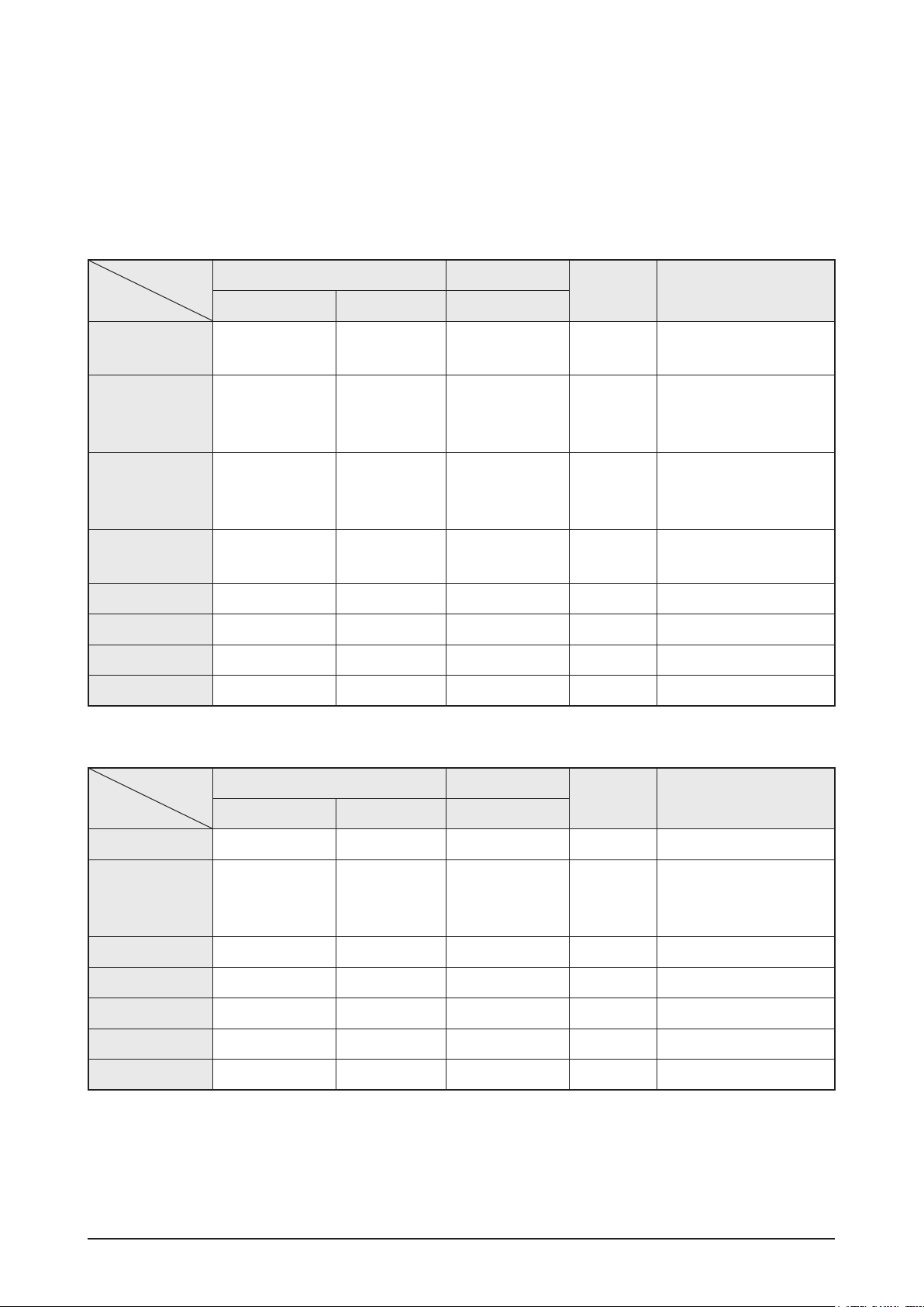
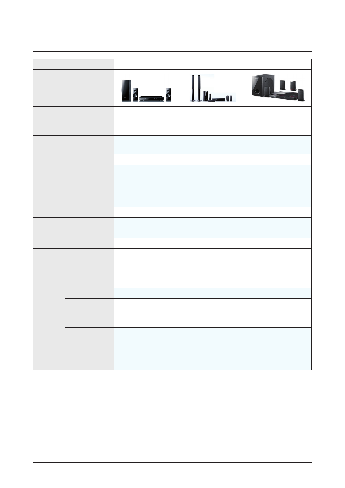
2-3 Specifications Analysis
Model Name HT-C5200 HT-BD3252 HT-BD1250
Photo
Profile
DVD, CD
MP3, JPG
USB HOST
i-POD / i-Phone
Wireless LAN
DivX
Wireless Rear
Memory Slot
DLNA, Widget
Energy-Star
BD-RE support
HDMI 1.3 1.3 1.3
1080P/ 24-frame
video
Blu-ray 2.0 from the
beginning
(MP4, HD JPG, MKV,
WMA, WMV)
(only USA)
(Ready) (Bundle included) (Ready)
(DivX-HD support) (DivX-HD support) (only EU / SD support)
(Ready) (Bundle included) (Ready)
X (External USB support) X (External USB support) X (External USB support)
0.27W 0.7W 0.7W
Support 1.0 Support 1.0 Support 1.0
Blu-ray 2.0 from the
beginning
X X
Blu-ray 2.0 from the
beginning
HDMI
CEC (Anynet+)
Deep Color
xvYCC
HD Audio
Transmission
Picture Quality
control
(10 bit)
(Progressive Mode,
Still Mode, BD Wise,
Picture Control,
Sharpness, Movie)
X (8bit) X (8bit)
(Progressive Mode,
Still Mode, BD Wise,
Picture Control)
: Feature Included, X: Not Included
(Progressive Mode,
Still Mode, BD Wise,
Picture Control)
2-6 Samsung Electronics
Page 15
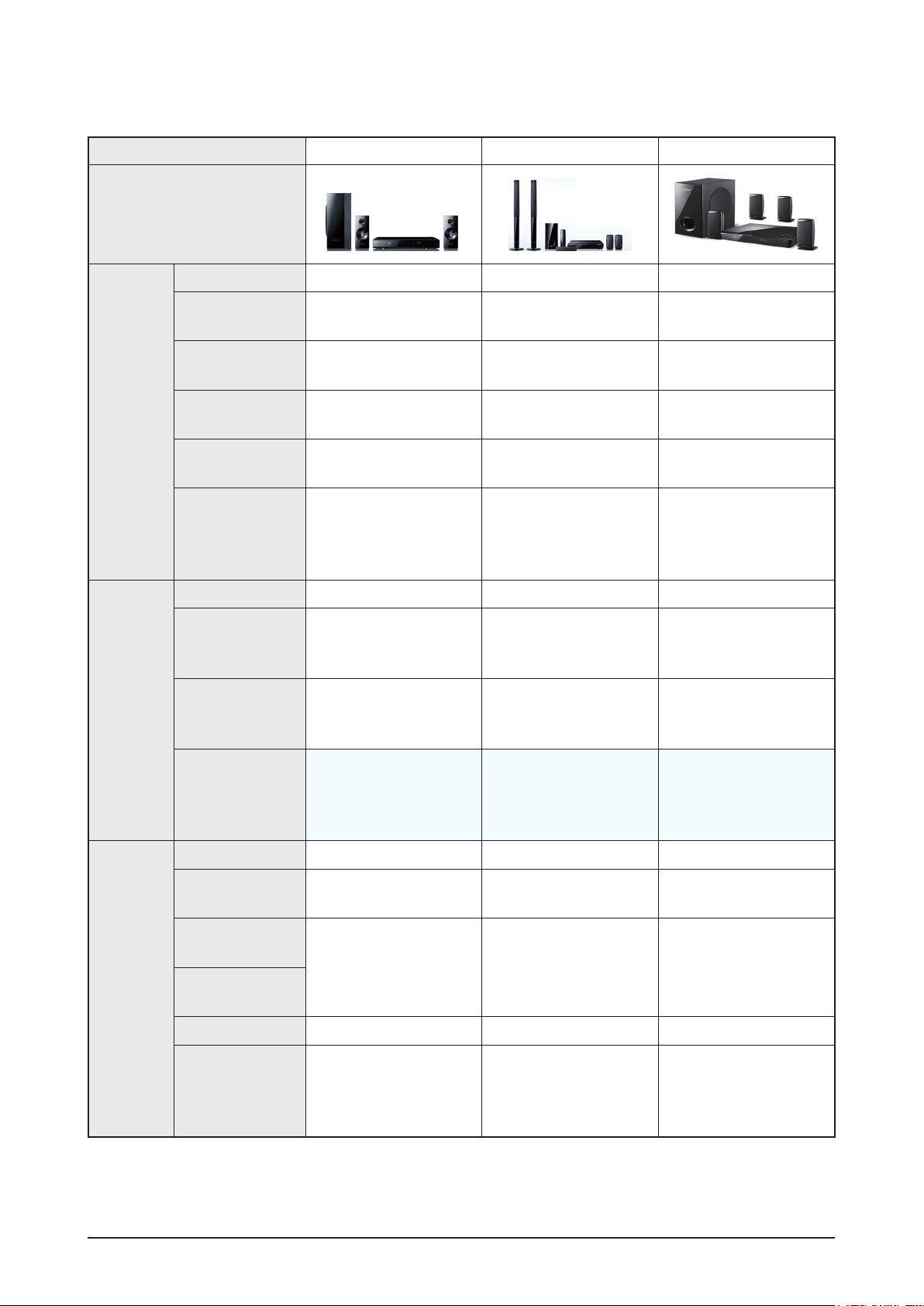
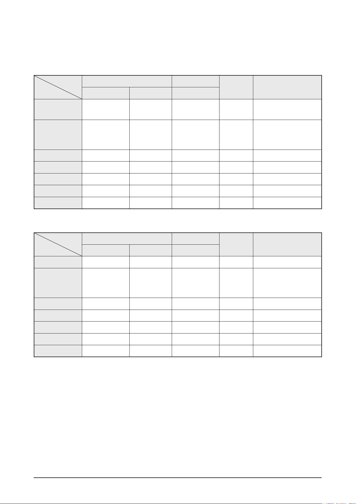
Product Specification
Model Name HT-C5200 HT-BD3252 HT-BD1250
Photo
Video
Video
Video Processor
1080P/ 60-frame
video
1080i/ 60-frame
video
1080P/ 24-frame
video
480i/p video
output for Blu-ray
Simultaneous
Video Output
between HDMI/
Component/CVBS
Factory Default
When connected
to a TV with
correct EDID
When conncted
to a TV with an
incorrect EDID
Main SOC Internal Scaler Main SOC Internal Scaler Main SOC Internal Scaler
480p 480p 480p
Maximum resolution for
TV input
480p 480p 480p
Maximum resolution for
TV input
Maximum resolution for
TV input
Audio
Remark
DD Plus decoding
Dolby TrueHD
decoding
DTS HD HRA
decoding
DTS-HD MA
decoding
Re-encoding
HD audio bit
stream output on
HDMI 1.3
HT-C5200 can also output
480i/480p resolution with
Blu-ray Disc
(DTS-HD Master Audio
essential)
(intoDTS) (into DTS) (into DTS)
DTS-HD MA Essential
dts-HD HRA
TrueHD
DD+
HT-BD3250 can also
output 480i/480p
resolution with Blu-ray
Disc
(DTS-HD Master Audio
essential)
DTS-HD MA Essential
dts-HD HRA
TrueHD
DD+
HT-BD1250 can also
resolution with Blu-ray
(DTS-HD Master Audio
DTS-HD MA Essential
: Feature Included, X: Not Included
output 480i/480p
Disc
essential)
dts-HD HRA
TrueHD
DD+
Samsung Electronics 2-7
Page 16
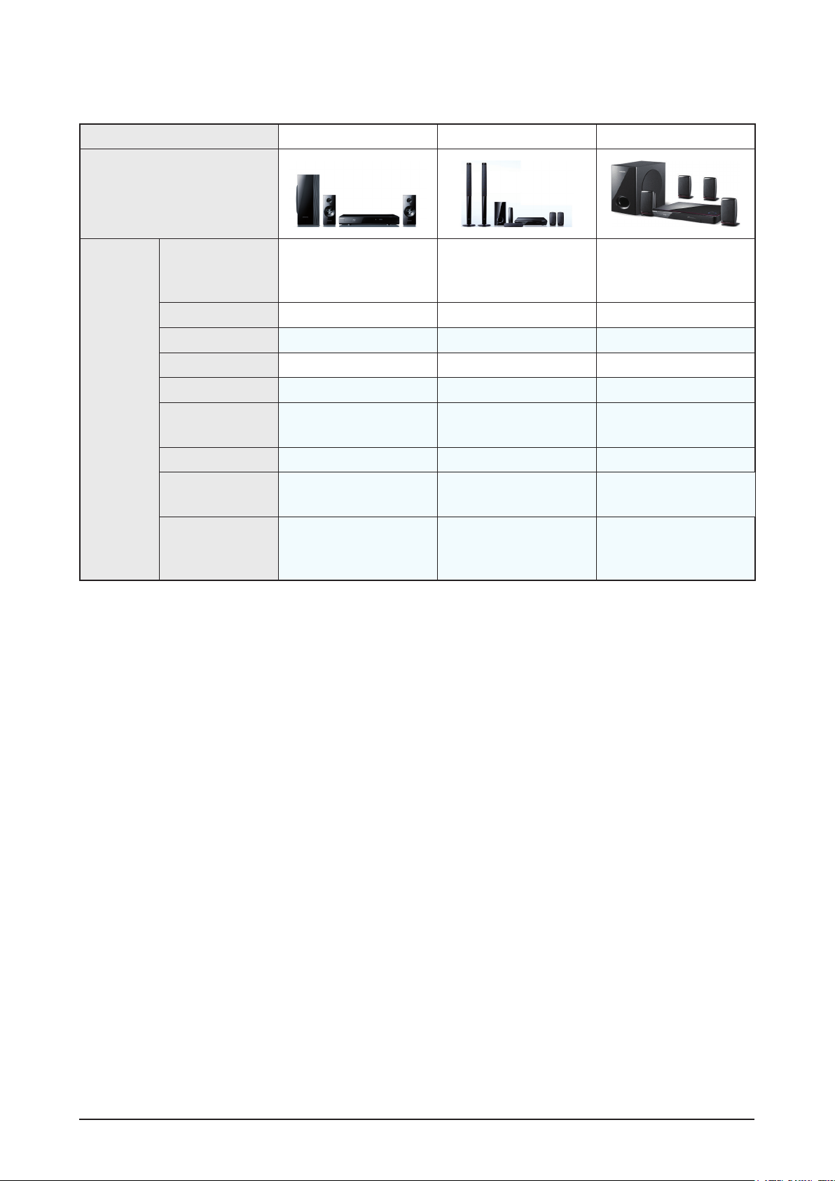
Product Specification
Model Name HT-C5200 HT-BD3252 HT-BD1250
Photo
H/W
2 trans
SMPS
Deck Draw type Plastic Cover Draw type Plastic Cover Draw type Plastic Cover
Pick Up
Front Micom
MAIN CHIP
Wireless Rear
Speaker
WiFi Lan Dongle
HDMI IN
Main↔Loader
Stand-By Power
Consumption 0.7W
6G VE Pickup 5G VE Pickup 5G VE Pickup
SANYO SANYO SANYO
BCM7630 BCM7601 BCM7440
X Included (SWA-4100) Ready (SWA-5100)
Ready Included Ready
X (Except USA, all support
2 Input)
One Board
(BCM 7630 - Back end,
SoC chip - Front end)
(BCM 7601 - Back end,
2 trans
Stand-By Power
Consumption 0.7W
2 Inputs support X
One Board
BCM7620 - Front end)
Stand-By Power
Consumption 0.7W
(BCM 7440 - Back end,
BCM7620 - Front end)
2 trans
One Board
: Feature Included, X: Not Included
2-8 Samsung Electronics
Page 17
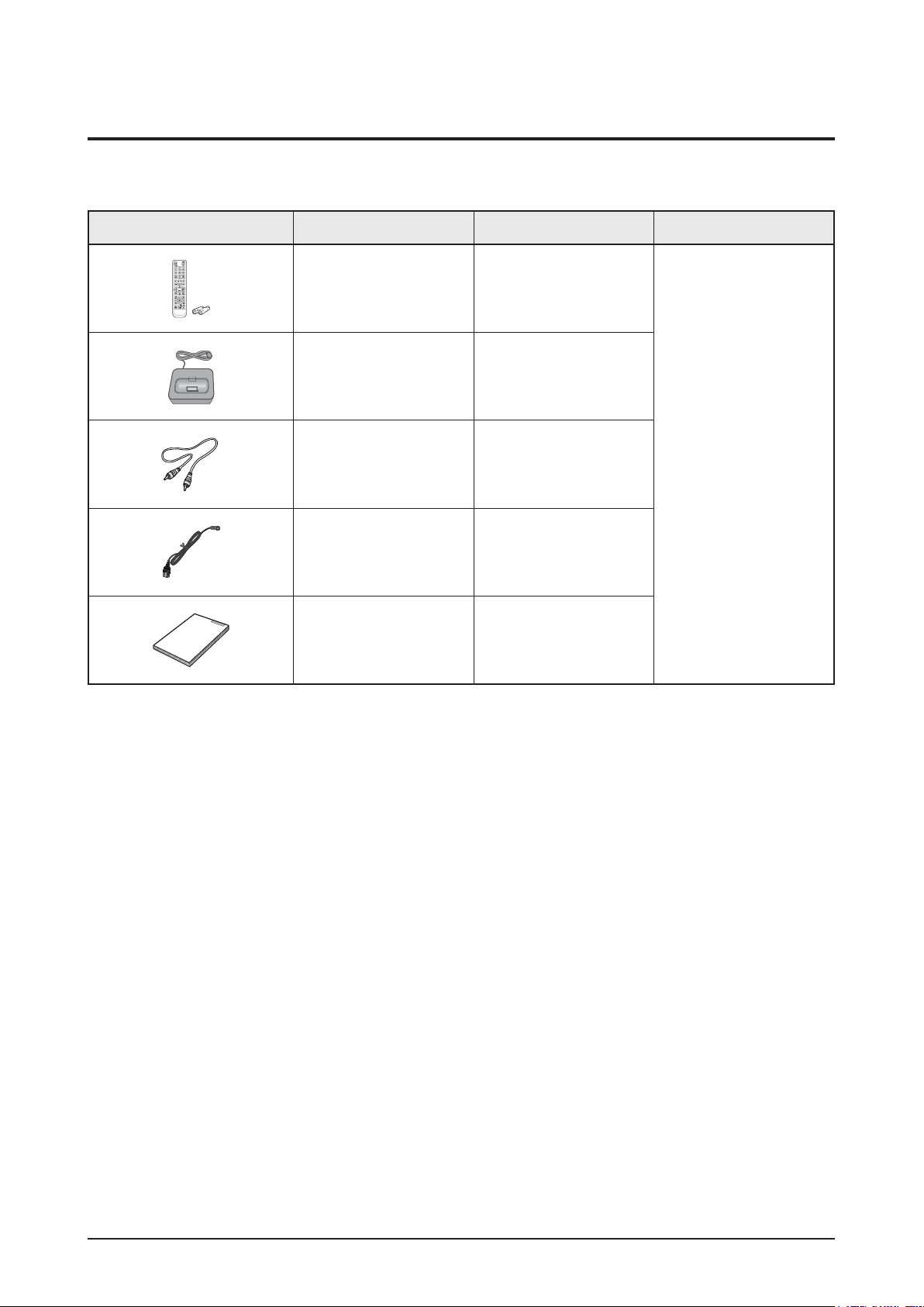
2-4 Accessories
2-4-1 Supplied Accessories
Accessories Item Item code Remark
Product Specification
Remote Control
Battery
iPod Dock AH96-00051A
Video Cable AH39-40001V
FM Antenna AH42-00021A
User’s Manual AH68-02257F
AH59-02303A
4301-001035
Local Samsung Dealer
Samsung Electronics 2-9
Page 18

MEMO
2-10 Samsung Electronics
Page 19
Disassembly & Reassembly
3. Disassembly & Reassembly
3-1 Overall Disassembly & Reassembly
- Be careful to follow the disassembly sequence described in the manual. Otherwise, the product
may be damaged.
- Be sure to carefully read and understand the safety instructions before performing any work as
the IC chips on the PCB are vulnerable to static electricity.
- In order to assemble reverse the order of disassembly.
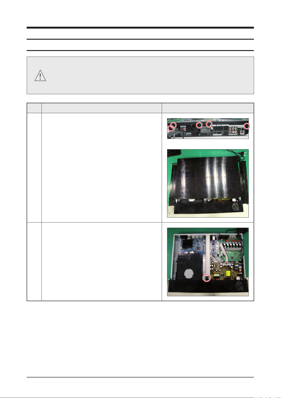
No. Description Description Photo
1 1) Unfasten 5 screws on the DECO-SIDE.
2) Remove DECO-SIDE & TOP on the direction of Rear.
2 1) Unfasten 1 screw to remove CABINET-FRONT.
Samsung Electronics 3-1
Page 20
Disassembly & Reassembly
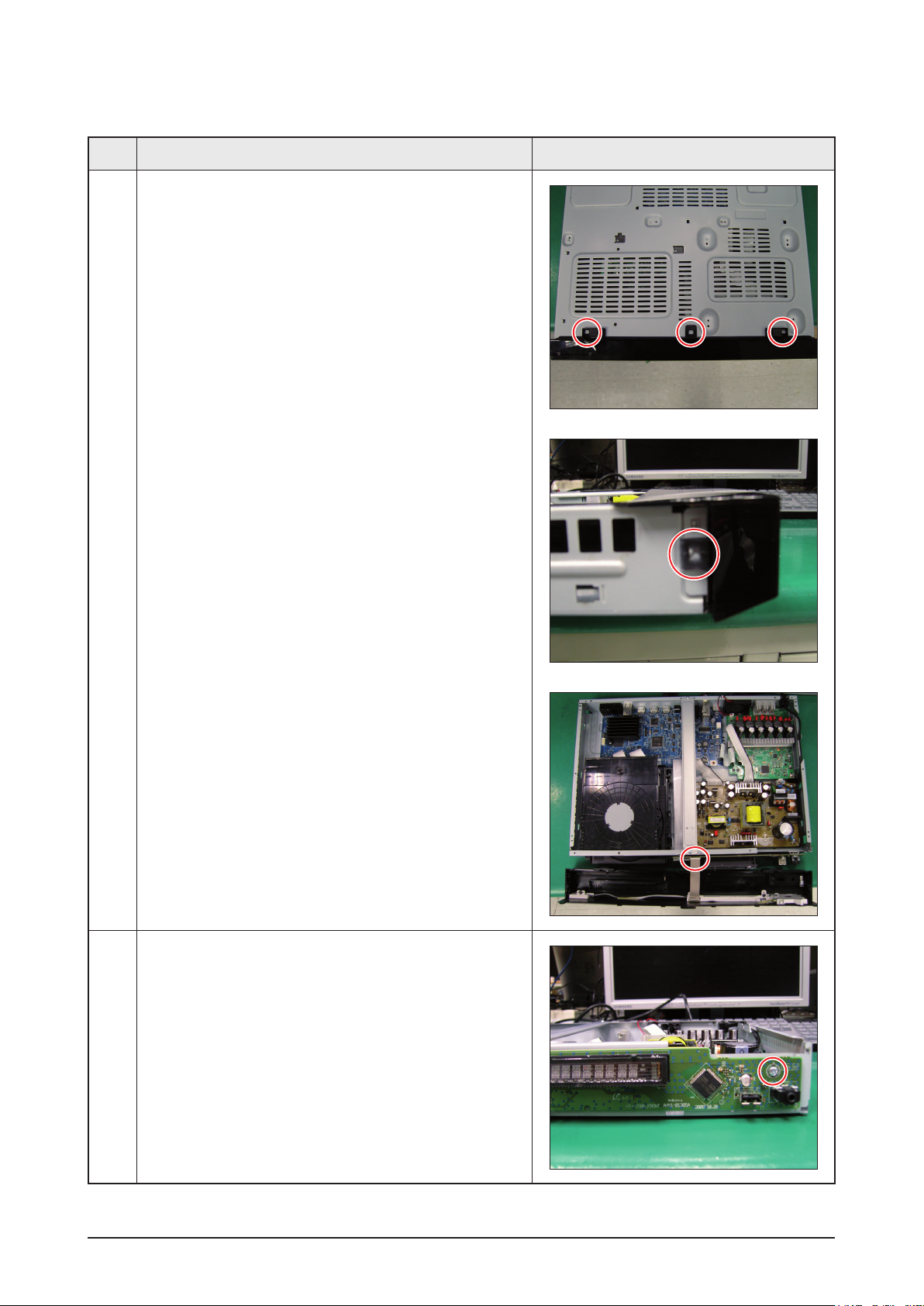
No. Description Description Photo
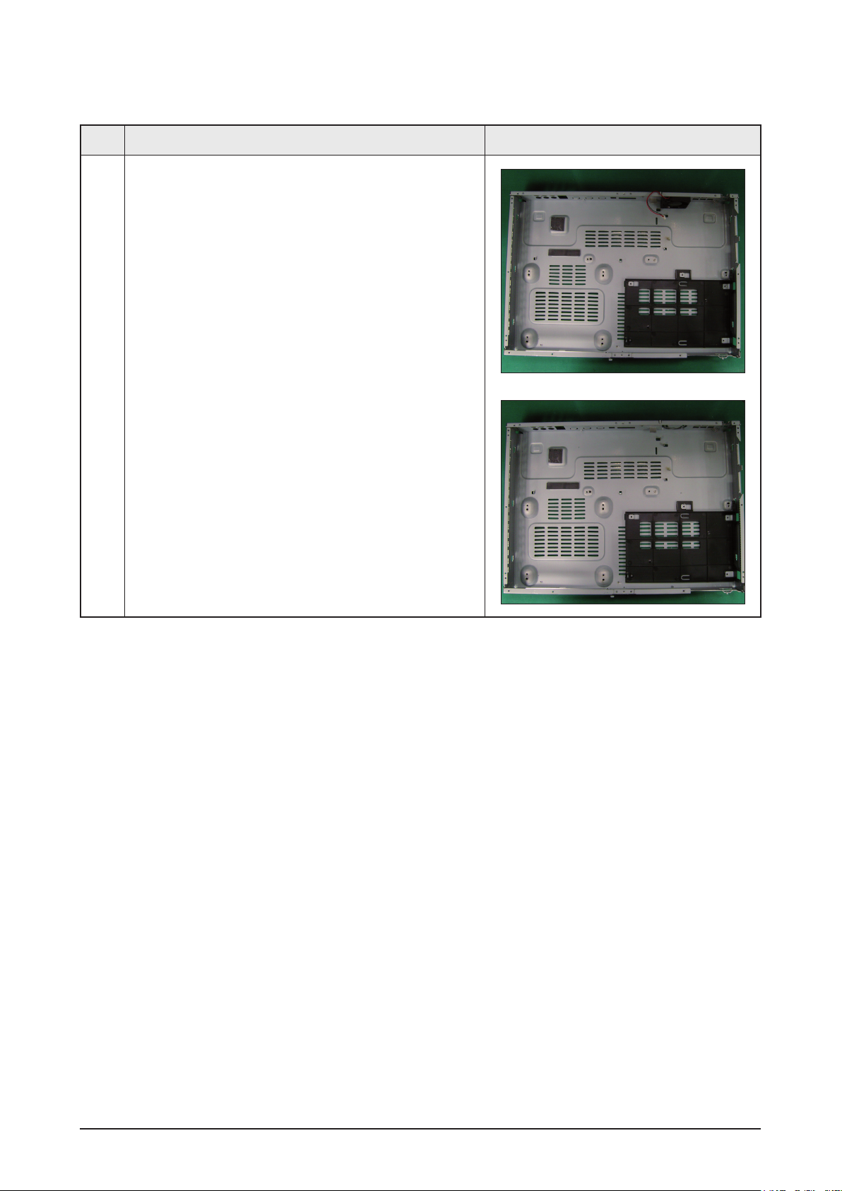
2 2) Loosen hooks from CABINET-BOTTOM.
3) Disconnect wire, then remove the
CABINET-BOTTOM.
3 1) Unfasten 1 screw, then remove ASSY PCB FRONT.
3-2 Samsung Electronics
Page 21
Disassembly & Reassembly
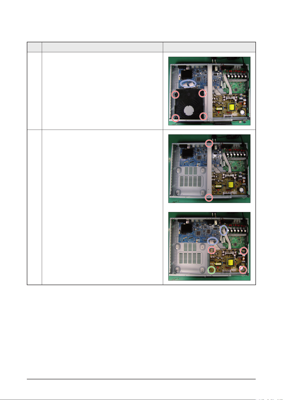
No. Description Description Photo
4 1) Unfasten 4 screws, disconnect FPC wire, and remove
ASSY-DECK.
5 1) Unfasten 2 screws, then remove BRACKET-TOP.
2) Unfasten 3 screws, loosen 1 hook, and disconnect
2 wires and remove ASSY-SMPS and POWER-
CORD.
Samsung Electronics 3-3
Page 22
Disassembly & Reassembly
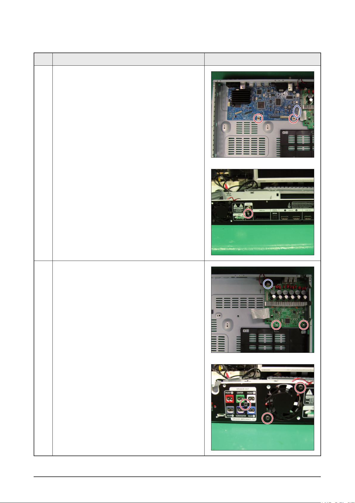
No. Description Description Photo
6 1) Unfasten 2 screws and 1 wire, then remove
ASSY PCB MAIN.
7 1) Unfasten 5 screws to remove AMP and FAN.
3-4 Samsung Electronics
Page 23
Disassembly & Reassembly
No. Description Description Photo
8 1) Remove ASSY PCB AMP and FAN.
Samsung Electronics 3-5
Page 24
Disassembly & Reassembly
3-2 DECK Disassembly & Reassembly
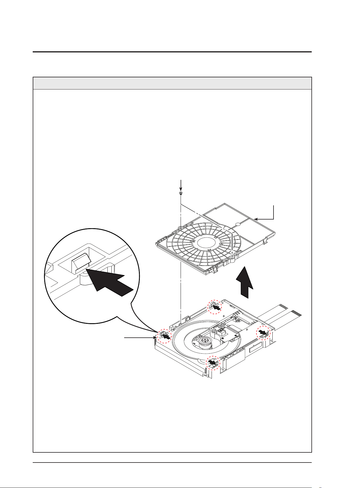
3-2-1 Ass’y Cover Removal
Description
1. Remove 2 Screws
1.
2. Push 4 Hooks 2 in the Direction of Arrow “A”.
3. Lift up the Ass’y Cover 3 in direction of arrow “B”.
1 2 SCREWS
(M 2 X 7 W)
3 ASS'Y COVER
2 4 HOOKS
“A”
“A”
“A”
“A”
3-6 Samsung Electronics
Page 25
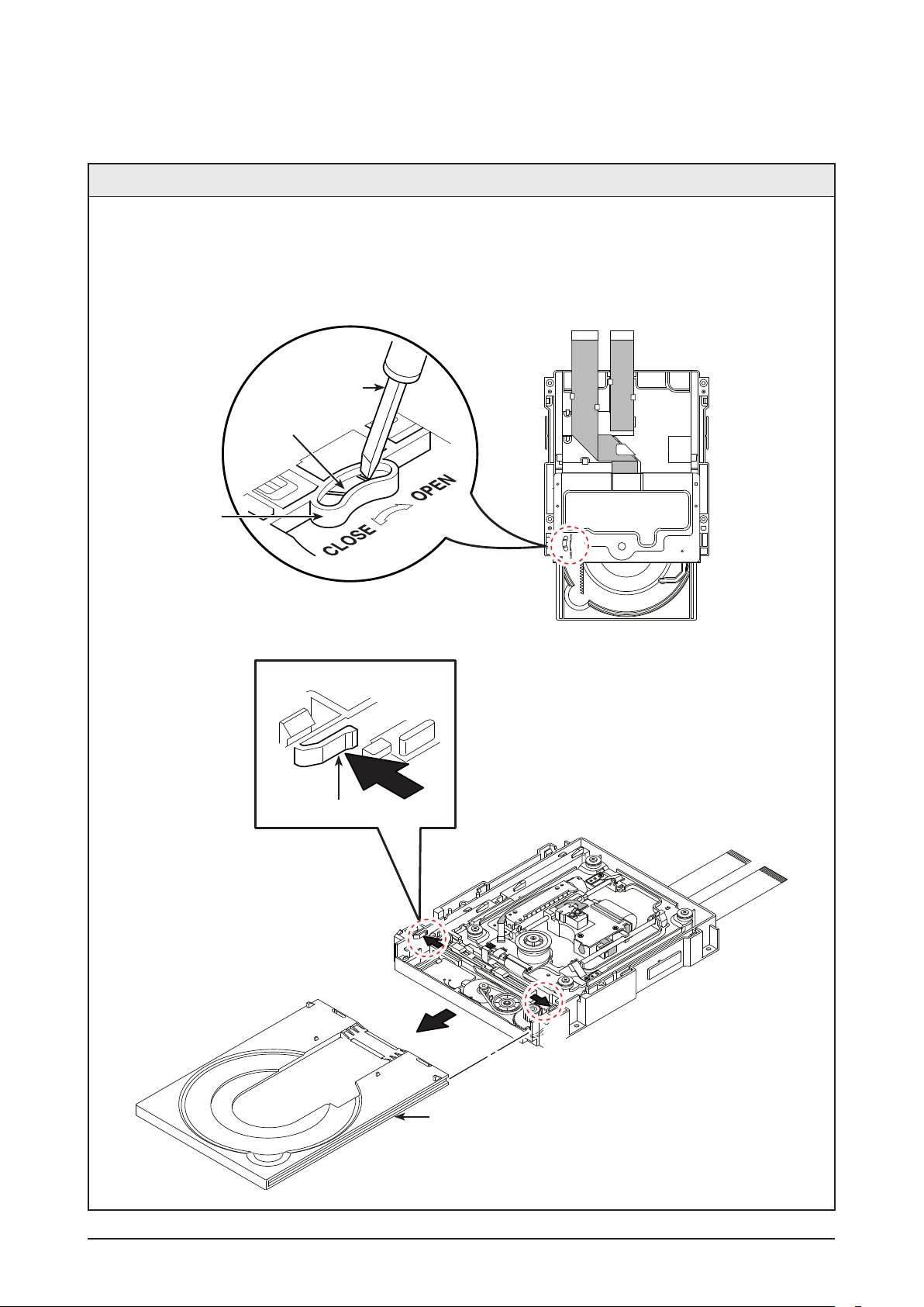
3-2-2 Tray Disc Removal
Disassembly & Reassembly
Description
1. Insert a Screw Driver into Hole
1 and rotate Gear Tray 2 in the direction arrow “Open”.
2. When the Tray Disc 3 comes out a little, pull in the direction of arrow “A” using your hand.
3. Pull the Tray Disc 3 to disassemble, while simultaneously pushing 2 Stoppers 4 (left, right) in the
direction arrow “B”, “C”.
SCREW DRIVER
2 GEAR TRAY
1 HOLE
(BOTTOM VIEW)
4 STOPPER
“B”
“A”
“C”
3 TRAY DISC
(TOP VIEW)
Samsung Electronics 3-7
Page 26
Disassembly & Reassembly
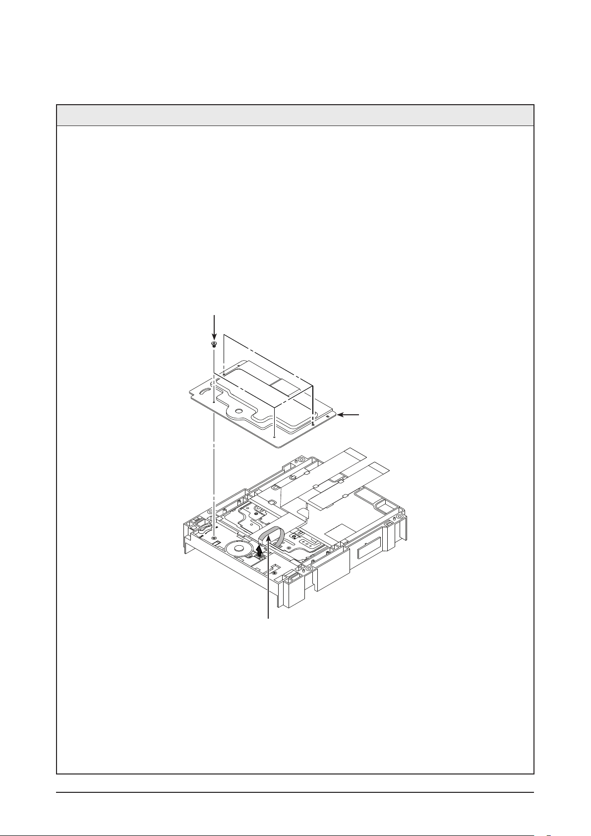
3-2-3 Cover Bottom Removal (Optional)
Description
1. Remove 4 Screws
1.
2. Lift up the Cover Bottom 2.
3. Remove FFC Cable 3.
1 4 SCREWS
(M 1.7 X 5 W)
2 COVER BOTTOM
3 FFC CABLE
3-8 Samsung Electronics
Page 27
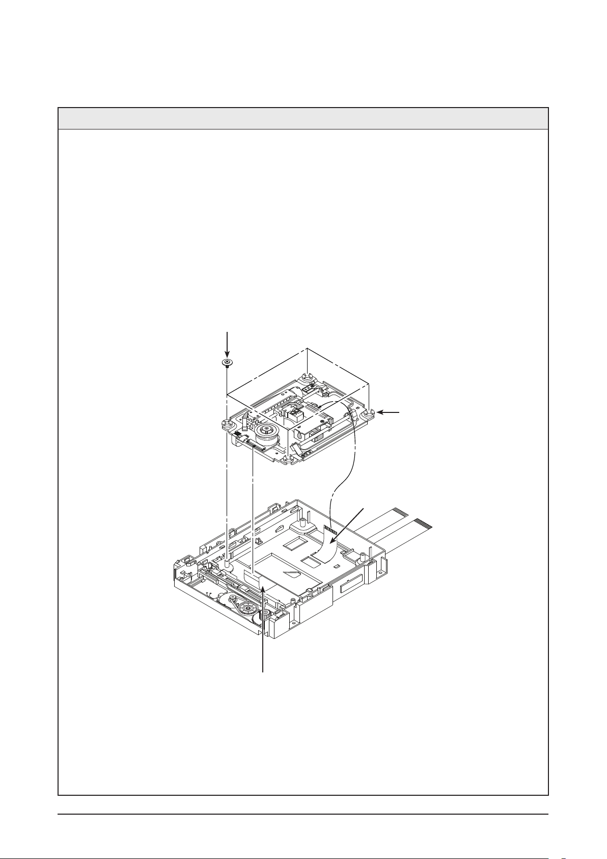
3-2-4 Assy Traverse Deck Removal
Disassembly & Reassembly
Description
1. Remove FFC PU Cable
1.
2. Removal 4 Screws 2.
3. Lift up the Assy Traverse Deck 3.
4. Remove FFC Deck Cable 4.
2 4 SCREWS
(M 2.6 X 6 B)
3 ASS’Y TRAVERSE DECK
4 FFC DECK
1 FFC PU
Samsung Electronics 3-9
Page 28
Disassembly & Reassembly
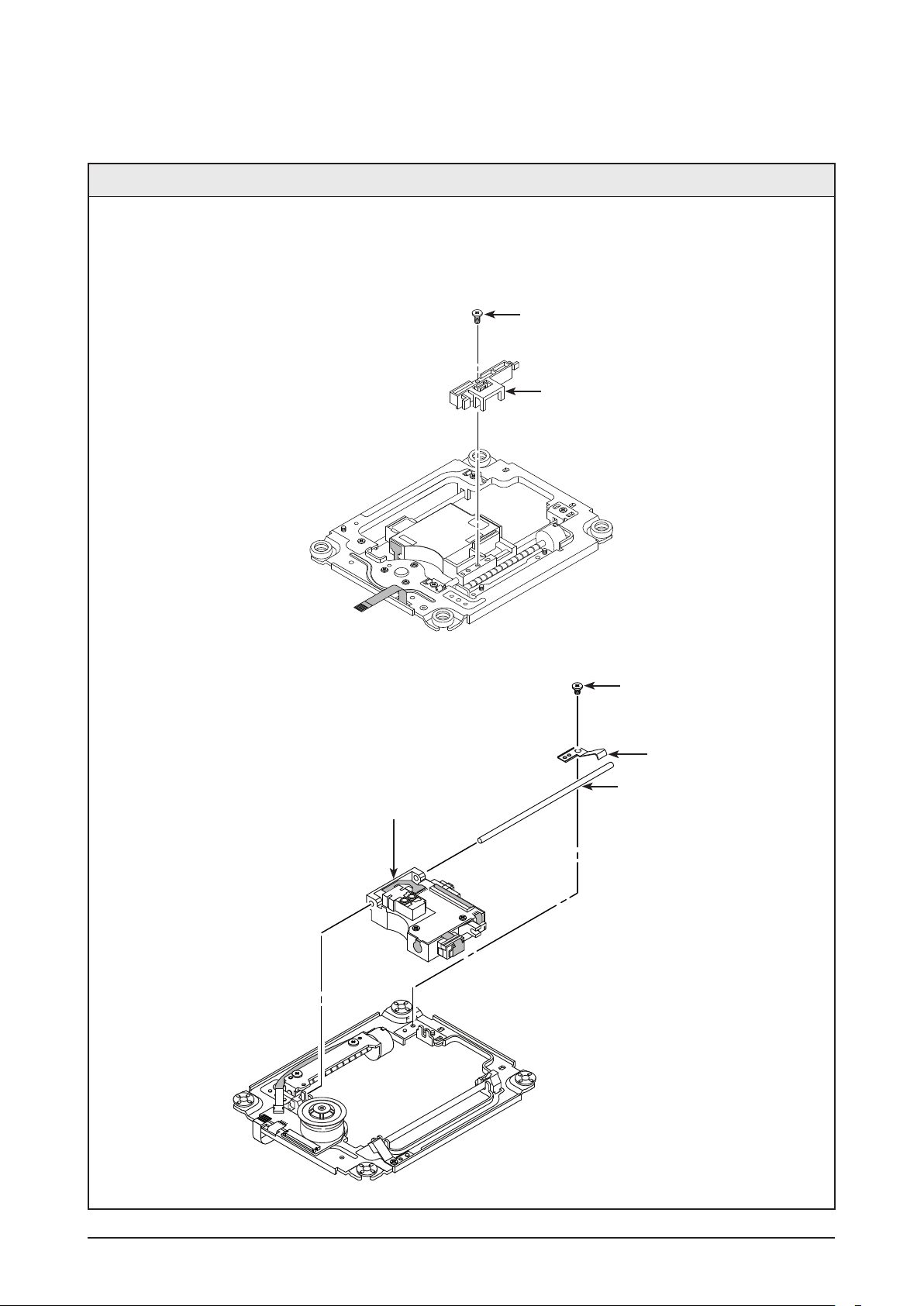
3-2-5 Ass’y Pick Up Removal
Description
1. Remove 1 Screw
1 and Lift up the Assy Hinge PU 2.
2. Remove 1 Screw 3 and Lift up Brkt Shaft Fix R 4.
3. Lift Up Shaft P/U 5 and Remove the Ass’y Pick Up 6.
(BOTTOM VIEW)
1 1 SCREW
(M 1.7 X 5 W)
2 ASS'Y HINGE PU
6 ASS'Y PICK UP
3 1 SCREW
(M 1.7 X 5 W)
4 BRKT SHAFT FIX R
5 SHAFT P/U
(TOP VIEW)
3-10 Samsung Electronics
Page 29
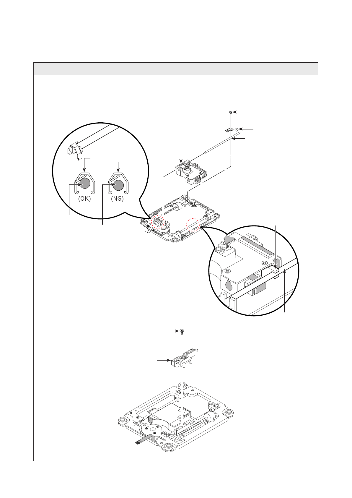
3-2-6 Ass’y Pick Up Assemble
Disassembly & Reassembly
Description
1. Insert the Shaft P/U
1 into the Ass’y pick up 2.
2. Insert the Brkt Shaft Fix R 3 Assemble 1 Screw 4.
3. Insert the Ass’y Hinge PU 5 Assemble 1 Screw 6.
2 ASS'Y PICK UP
BRACKET SHAFT PU
SHAFT P/U
SHAFT P/U
4 1 SCREW
(M 1.7 X 5 W)
3 BRKT SHAFT FIX R
1 SHAFT P/U
ASS'Y PICK UP
SHAFT P/U
6 1 SCREW
(M 1.7 X 5 W)
5 ASS'Y HINGE PU
Samsung Electronics 3-11
Page 30

MEMO
3-12 Samsung Electronics
Page 31
4. Troubleshooting
4-1 Checkpoints by Error Mode
Oscilloscope Setting Values
Voltage/DIV 1V/div
TIME/DIV 500ms/div
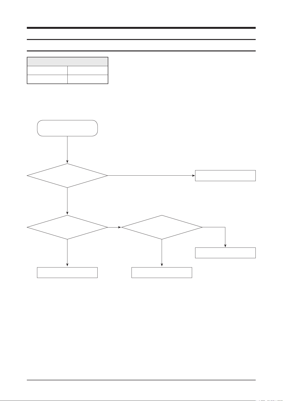
4-1-1 No Power
No Power Detected
(Stand by LED OFF)
Troubleshooting
F1R and CON1
are shorted?(SMPS)
Yes
Is there 5.4V in CON3
pin 12, 13, and 14?
Yes
Check MAIN PCB.
No
No
Is there 2.5V in
ICFB5401 pin 1?
Yes
Check MAIN PCB.
Change Fuse.
No
Change SMPS.
Samsung Electronics 4-1
Page 32

Troubleshooting
4-1-2 No Sound
There is no audio sound from speaker.
AMP CON1 Pin 20 ~ 25 Signal Check?
Yes
Check AMP PCB L10 ~ 15?
Yes
Check the signal output from
jack(SP1) and if there is no signal,
change AMP PCB.
No
No
Change MAIN PCB.
Change AMP PCB.
4-2 Samsung Electronics
Page 33

4-1-3 Disc Loading Error
Disc Loading Error
Troubleshooting
Check whether there is
3.3V in CN14, 5V in IC19, and12V in IC20,
which are all located in the
Main PCB Deck?
Yes
Is the Deck cable
(between MAIN & DECK)
inserted correctly?
Yes
Change the DECK.
No
No
Check SMPS 12V, 5.3V.
Reinsert DECK cables correctly.
Samsung Electronics 4-3
Page 34

Troubleshooting
4-1-4 Remote doesn’t work
Remote control does not work
Remote Battery OK?
Yes
Is the FFC Cable
(between Front panel & MAIN)
properly connected?
Yes
1
REYE Pin 1 Signal OK?
Yes
Refer to wave pattern
image of Fig. 4-1.
No
No
No
Check the Battery.
Re-insert FFC cable correctly.
Change REYE or change the
FRONT PCB.
(How to check REYE.
Pin 1 - SIGNAL OUT,
Pin 2 - VCC 5V, Pin 3 - GND
Check pin 1 signal when you press
any Remote button. If the signal
is not output, change the Remote
Module. / Checnk pin 2 if the voltage
level is 4.75V~5.25V or not. It must
be between 4.75~5.25V.)
Change the power of IC1302 Pin 7,
change the MAIN PCB.
4-4 Samsung Electronics
Page 35

ST 5. 4V
D_G ND
ST 5V
FC 1
47 nF
RC D1
20 0m A
FR 7
47
FC 2
10 00 0n F
REMO _IN
VFD_ -28V
VFD-
DS 5V
RE YE
HO RI ZO NT AL
1
OUT
3
GND
2
VCC
REMOCON-EYE PARTS
R E Y E
F C 1
F C 2
R C D 1
F R 7
V F C 7
I C 1
E C C 1
E C C 3
E C C 4
HT-C55 00_FRONT
1
Troubleshooting
1
FRONT PCB Top, page 6-2
<Fig. 4-1>
1
<Remote Eye Data>
FRONT, page 7-2
Samsung Electronics 4-5
Page 36

Troubleshooting
4-1-5 No Picture
No Picture
Logo screen is OK?
Yes
BD/DVD Playback is OK?
Yes
Change the MAIN PCB
No
No
HDMI?
Yes
Component?
Yes
C. No Logo
(CVBS / S-Video)
No
A. No Logo (HDMI)
No
B. No Logo (HDMI)
4-6 Samsung Electronics
Page 37

4-1-6 No Picture (HDMI) - Label A
No Picture (HDMI)
Troubleshooting
Video selection
accords with cable connection and
TV mode?
Yes
1
Check D401 ~ D402 signal?
Yes
Refer to wave pattern
image of Fig. 4-2 and
Fig. 4-3.
2
Signal from VT11 ~ VT19 check?
Yes
Refer to wave pattern
image of Fig. 4-4.
No
No
No
Check the Video select, cable
connection, TV mode.
Check IC402, IC501 prepheral circult.
X401 oscillation, power 3.3V and 1.8V.
2
Check R624 ~ R637. If there is no
signal, change IC501.
Refer to wave pattern
image of Fig. 4-5.
Check CN4 soldering status?
Yes
HDMI Cable Error
No
Check HIC6 peripheral devices like
power and soldering.
Samsung Electronics 4-7
Page 38

Troubleshooting
14. NC
PORT0
P0_5V
P0_5V
D5.0V_PW
P0_5V
D5.0V_PW
P0_PWR5V
4C5>
RX10M
RX10P
RX20P
RXO0P
RXO0M
RXC0P
RXC0M
RX20M
HT0_CTLB
FD05015-19
CN401
1
10
11
12
13
14
15
16
17
18
19
2
3
4
5
6
7
8
9
MGND1
MGND2
MGND3
MGND4
DGND
RCLAMP0524P.TCT
D402
1 10
2
3
4
5 6
7
8
9
DGND
RCLAMP0524P.TCT
D401
1 10
2
3
4
5 6
7
8
9
DGND
DGND
5D4<
5D5<
5D4<
5D4<
5D4<
5D4<
5D4<
5D4<
DGND
NC
R429
10KOHM
1/16W
R463
1/16W
10KOHM
R464
DGND
1KOHM
1/16W
R401
1/16W
47KOHM
R403
DGND
56KOHM
1/16W
RE71
0OHM
1/16W
R409
1/16W
0OHM
R408
0OHM
1/16W
R407
1/16W
10KOHM
R405
NC
R413NCR423
RXSCL0
4E3<
6E8<
3F1<>
HDMI_CEC
RXSDA0
5C2<> DTC124EK
Q403
1/16W
330OHM
R425
2SA1979S-Y
Q401
4C7>
1/16W
1KOHM
R431
1/16W
10KOHM
R427
DGND
16V
100NF
C401
P1[3]
P1[4]
P1[5]
P1[6]
P1[7]
VDD
VDD
X1_IN
P2[0]
P2[1]
P2[2]
P2[3]
OUT_LINES
GND
OUT_LINESIN_LINES
GND
IN_LINES
IN_LINES
IN_LINES OUT_LINES
OUT_LINES
OUT_LINES
GND
OUT_LINESIN_LINES
GND
IN_LINES
IN_LINES
IN_LINES OUT_LINES
OUT_LINES
E
B
C
EBC
SDAVSS
WP
VCC
SCLA2
A1
A0
GND
OUTIN
OUT
GND
OUTIN
14. NC
PORT0
P0_5V
P0_5V
D5.0V_PW
P0_5V
D5.0V_PW
FD05015-19
DGND
RCLAMP0524P.TCT
DGND
RCLAMP0524P.TCT
DGND
DGND
DGND
NC
10KOHM
1/16W
1/16W
10KOHM
DGND
1KOHM
1/16W
1/16W
47KOHM
DGND
56KOHM
1/16W
0OHM
1/16W
1/16W
0OHM
0OHM
1/16W
1/16W
10KOHM
NC
NC
DTC124EK
1/16W
330OHM
2SA1979S-Y
1/16W
1KOHM
1/16W
10KOHM
DGND
16V
100NF
CN401
D402
D401
R429
R463
R464
R401
R403
RE71
R409
R408
R407
R405
R413
R423
Q403
R425
Q401
R431
R427
C401
4C5>
5D4<
5D5<
5D4<
5D4<
5D4<
5D4<
5D4<
5D4<
4E3<
6E8<
3F1<>
5C2<>
4C7>
P0_PWR5V
RX10M
RX10P
RX20P
RXO0P
RXO0M
RXC0P
RXC0M
RX20M
HT0_CTLB
RXSCL0
HDMI_CEC
RXSDA0
1
10
11
12
13
14
15
16
17
18
19
2
3
4
5
6
7
8
9
MGND1
MGND2
MGND3
MGND4
1 10
2
3
4
5 6
7
8
9
1 10
2
3
4
5 6
7
8
9
OUT_LINES
GND
OUT_LINESIN_LINES
GND
IN_LINES
IN_LINES
IN_LINES OUT_LINES
OUT_LINES
OUT_LINES
GND
OUT_LINESIN_LINES
GND
IN_LINES
IN_LINES
IN_LINES OUT_LINES
OUT_LINES
E
B
C
EBC
IC402
1
4-8 Samsung Electronics
1
MAIN PCB Top, page 6-9
<Fig. 4-2>
HDMI MICOM, page 7-10
1
<HDMI EYE SIGNAL>
Page 39

14. NC
PORT1
14. NC
PORT0
P1_5V
P1_5V D5.0V_PW
P1_5V
P0_5V
P0_5V
D5.0V_PW
P0_5V
D5.0V_PW
4C5>
P1_PWR5V
P0_PWR5V
4C5>
RX21P
RX21M
RX01M
RX11P
RX11M
RX01P
HT1_CTLB
RXC1M
RXC1P
RX10M
RX10P
RX20P
RXO0P
RXO0M
RXC0P
RXC0M
RX20M
I2C_INT
EP94A2_INTB
HT0_CTLB
EPF021A_P70
EPF021A_OP0
EPF021A_P71
CN402
1
10
11
12
13
14
15
16
17
18
19
2
3
4
5
6
7
8
9
MGND1
MGND2
MGND3
MGND4
DGND
RCLAMP0524P.TCT
D404
1 10
2
3
4
5 6
7
8
9
DGND
RCLAMP0524P.TCT
D403
1 10
2
3
4
5 6
7
8
9
1KOHM
1/16W
R402
47KOHM
1/16W
R404
DGND
56KOHM
1/16W
RE73
0OHM
1/16W
R412
1/16W
0OHM
R411
1/16W
10KOHM
R406
1/16W
0OHM
R410
NC
R414NCR424
FD05015-19
CN401
1
10
11
12
13
14
15
16
17
18
19
2
3
4
5
6
7
8
9
MGND1
MGND2
MGND3
MGND4
DGND
DGND
RCLAMP0524P.TCT
D402
1 10
2
3
4
5 6
7
8
9
DGND
RCLAMP0524P.TCT
D401
1 10
2
3
4
5 6
7
8
9
DGND
DGND
10OHM
R498
10OHM
R497
5D5<
5D5<
10OHM
R496
10OHM
R495
10OHM
R494
10OHM
R493
10OHM
R492
5D5<
5D5<
5D5<
5D5<
RXSCL1
3F1<>
HDMI_CEC
6E8<
4B3<
DGND
DTC124EK
Q404
5A4<>
RXSDA1
330OHM
1/16W
R426
2SA1979S-Y
Q402
10OHM
R491
DGND
NC
R430
5D5<
5D5<
4C7>
1/16W
1KOHM
R432
1/16W
10KOHM
R428
4D8<
4D8>
4C7>
DGND
DGND
5D4<
5D5<
5D4<
5D4<
5D4<
5D4<
5D4<
5D4<
DGND
NC
R429
14E8<
TP425
TP434
10KOHM
1/16W
R463
1/16W
10KOHM
R464
DGND
1KOHM
1/16W
R401
1/16W
47KOHM
R403
DGND
56KOHM
1/16W
RE71
0OHM
1/16W
R409
1/16W
0OHM
R408
0OHM
1/16W
R407
1/16W
10KOHM
R405
NC
R413NCR423
RXSCL0
4E3<
6E8<
3F1<>
HDMI_CEC
RXSDA0
5C2<> DTC124EK
Q403
1/16W
330OHM
R425
2SA1979S-Y
Q401
4C7>
1/16W
1KOHM
R431
1/16W
10KOHM
R427
DGND
16V
100NF
C401
ADC[2]
ADC[3]
PWM[0]
PWM[1]
TIM[0]
TIM[1]
VSS
X2_OUT
X2_IN
RESERVED
P3[0]
P3[1]
P3[2]
P3[3]
P3[4]
P1[3]
P1[4]
P1[5]
P1[6]
P1[7]
EXT_INT
VDD
VDD
X1_OUT
X1_IN
OP_MODE[0]
OP_MODE[1]
P2[0]
P2[1]
P3[5]
P0[1]
VSSA
P0[0]
VREFL
P1[2]
P1[1]
P1[0]
P2[2]
P2[3]
P2[4]
P2[5]
P2[6]
P2[7] SPI_CLK
SPI_DO
SPI_DI
VSS
P0[7]
P0[6]
P0[5]
P0[4]
P0[3]
P0[2]
P3[6]
P3[7]
RSTB
ID
DM
DP
VBUS
VDDA
VREFH
ADC[0]
ADC[1]
OUT_LINES
GND
OUT_LINESIN_LINES
GND
IN_LINES
IN_LINES
IN_LINES OUT_LINES
OUT_LINES
OUT_LINES
GND
OUT_LINESIN_LINES
GND
IN_LINES
IN_LINES
IN_LINES OUT_LINES
OUT_LINES
OUT_LINES
GND
OUT_LINESIN_LINES
GND
IN_LINES
IN_LINES
IN_LINES OUT_LINES
OUT_LINES
OUT_LINES
GND
OUT_LINESIN_LINES
GND
IN_LINES
IN_LINES
IN_LINES OUT_LINES
OUT_LINES
E
B
C
EBC
E
B
C
EBC
SDAVSS
WP
VCC
SCLA2
A1
A0
GND
OUTIN
OUT
GND
OUTIN
14. NC
PORT1
14. NC
PORT0
P1_5V
P1_5V D5.0V_PW
P1_5V
P0_5V
P0_5V
D5.0V_PW
P0_5V
D5.0V_PW
DGND
RCLAMP0524P.TCT
DGND
RCLAMP0524P.TCT
1KOHM
1/16W
47KOHM
1/16W
DGND
56KOHM
1/16W
0OHM
1/16W
1/16W
0OHM
1/16W
10KOHM
1/16W
0OHM
NC
NC
FD05015-19
DGND
DGND
RCLAMP0524P.TCT
DGND
RCLAMP0524P.TCT
DGND
DGND
10OHM
10OHM
10OHM
10OHM
10OHM
10OHM
10OHM
DGND
DTC124EK
330OHM
1/16W
2SA1979S-Y
10OHM
DGND
NC
1/16W
1KOHM
1/16W
10KOHM
DGND
DGND
DGND
NC
10KOHM
1/16W
1/16W
10KOHM
DGND
1KOHM
1/16W
1/16W
47KOHM
DGND
56KOHM
1/16W
0OHM
1/16W
1/16W
0OHM
0OHM
1/16W
1/16W
10KOHM
NC
NC
DTC124EK
1/16W
330OHM
2SA1979S-Y
1/16W
1KOHM
1/16W
10KOHM
DGND
16V
100NF
CN402
D404
D403
R402
R404
RE73
R412
R411
R406
R410
R414
R424
CN401
D402
D401
R498
R497
R496
R495
R494
R493
R492
Q404
R426
Q402
R491
R430
R432
R428
R429
TP425
TP434
R463
R464
R401
R403
RE71
R409
R408
R407
R405
R413
R423
Q403
R425
Q401
R431
R427
C401
4C5>
4C5>
5D5<
5D5<
5D5<
5D5<
5D5<
5D5<
3F1<>
6E8<
4B3<
5A4<>
5D5<
5D5<
4C7>
4D8<
4D8>
4C7>
5D4<
5D5<
5D4<
5D4<
5D4<
5D4<
5D4<
5D4<
14E8<
4E3<
6E8<
3F1<>
5C2<>
4C7>
P1_PWR5V
P0_PWR5V
RX21P
RX21M
RX01M
RX11P
RX11M
RX01P
HT1_CTLB
RXC1M
RXC1P
RX10M
RX10P
RX20P
RXO0P
RXO0M
RXC0P
RXC0M
RX20M
I2C_INT
EP94A2_INTB
HT0_CTLB
EPF021A_P70
EPF021A_OP0
EPF021A_P71
RXSCL1
HDMI_CEC
RXSDA1
RXSCL0
HDMI_CEC
RXSDA0
1
10
11
12
13
14
15
16
17
18
19
2
3
4
5
6
7
8
9
MGND1
MGND2
MGND3
MGND4
1 10
2
3
4
5 6
7
8
9
1 10
2
3
4
5 6
7
8
9
1
10
11
12
13
14
15
16
17
18
19
2
3
4
5
6
7
8
9
MGND1
MGND2
MGND3
MGND4
1 10
2
3
4
5 6
7
8
9
1 10
2
3
4
5 6
7
8
9
OUT_LINES
GND
OUT_LINESIN_LINES
GND
IN_LINES
IN_LINES
IN_LINES OUT_LINES
OUT_LINES
OUT_LINES
GND
OUT_LINESIN_LINES
GND
IN_LINES
IN_LINES
IN_LINES OUT_LINES
OUT_LINES
OUT_LINES
GND
OUT_LINESIN_LINES
GND
IN_LINES
IN_LINES
IN_LINES OUT_LINES
OUT_LINES
OUT_LINES
GND
OUT_LINESIN_LINES
GND
IN_LINES
IN_LINES
IN_LINES OUT_LINES
OUT_LINES
E
B
C
EBC
E
B
C
EBC
IC402
1
Troubleshooting
Samsung Electronics 4-9
1
MAIN PCB Top, page 6-9
<Fig. 4-3>
1
HDMI MICOM, page 7-10
<HDMI EYE SIGNAL>
Page 40

Troubleshooting
NC
TX1M
TX0P
TX0M
TX2M
TX1P
TX2P
TXCP
TXCM
FD05015-19
1
10
11
12
13
2
3
4
5
6
7
8
9
MGND2
MGND4
0OHM
R624
0OHM
R625
0OHM
R628
0OHM
R629
0OHM
R631
0OHM
R632
5A5>
5A5>
5A5>
5A5>
5A5>
5A5>
0OHM
R634
0OHM
R637
LOPIVA16G05
12V
VT11
LOPIVA16G05
12V
VT14
12V
LOPIVA16G05
VT12
LOPIVA16G05
12V
VT15
LOPIVA16G05
12V
VT16
5A5>
5A5>
LOPIVA16G05
12V
VT18
12V
LOPIVA16G05
VT19
LOPIVA16G05
12V
VT17
LOPIVA16G05
12V
VT21
12V
LOPIVA16G05
VT20
DGND
NC
FD05015-19
0OHM
0OHM
0OHM
0OHM
0OHM
0OHM
0OHM
0OHM
LOPIVA16G05
12V
LOPIVA16G05
12V
12V
LOPIVA16G05
LOPIVA16G05
12V
LOPIVA16G05
12V
LOPIVA16G05
12V
12V
LOPIVA16G05
LOPIVA16G05
12V
LOPIVA16G05
12V
12V
LOPIVA16G05
DGND
R624
R625
R628
R629
R631
R632
R634
R637
VT11
VT14
VT12
VT15
VT16
VT18
VT19
VT17
VT21
VT20
5A5>
5A5>
5A5>
5A5>
5A5>
5A5>
5A5>
5A5>
TX1M
TX0P
TX0M
TX2M
TX1P
TX2P
TXCP
TXCM
1
10
11
12
13
2
3
4
5
6
7
8
9
MGND2
MGND4
2
HDMI TX, page 7-12
2
2
4-10 Samsung Electronics
2
MAIN PCB Top, page 6-9
<Fig. 4-4>
<AC Level 300~500mV>
Page 41

NC
TX1M
TX0P
TX0M
TX2M
TX1P
TX2P
TXCP
TXCM
FD05015-19
1
10
11
12
13
2
3
4
5
6
7
8
9
MGND2
MGND4
0OHM
R624
0OHM
R625
0OHM
R628
0OHM
R629
0OHM
R631
0OHM
R632
5A5>
5A5>
5A5>
5A5>
5A5>
5A5>
0OHM
R634
0OHM
R637
LOPIVA16G05
12V
VT11
LOPIVA16G05
12V
VT14
12V
LOPIVA16G05
VT12
LOPIVA16G05
12V
VT15
LOPIVA16G05
12V
VT16
5A5>
5A5>
LOPIVA16G05
12V
VT18
12V
LOPIVA16G05
VT19
LOPIVA16G05
12V
VT17
LOPIVA16G05
12V
VT21
12V
LOPIVA16G05
VT20
DGND
NC
FD05015-19
0OHM
0OHM
0OHM
0OHM
0OHM
0OHM
0OHM
0OHM
LOPIVA16G05
12V
LOPIVA16G05
12V
12V
LOPIVA16G05
LOPIVA16G05
12V
LOPIVA16G05
12V
LOPIVA16G05
12V
12V
LOPIVA16G05
LOPIVA16G05
12V
LOPIVA16G05
12V
12V
LOPIVA16G05
DGND
R624
R625
R628
R629
R631
R632
R634
R637
VT11
VT14
VT12
VT15
VT16
VT18
VT19
VT17
VT21
VT20
5A5>
5A5>
5A5>
5A5>
5A5>
5A5>
5A5>
5A5>
TX1M
TX0P
TX0M
TX2M
TX1P
TX2P
TXCP
TXCM
1
10
11
12
13
2
3
4
5
6
7
8
9
MGND2
MGND4
2
Troubleshooting
HDMI TX, page 7-12
2
2
MAIN PCB Bottom, page 6-12
<Fig. 4-5>
<AC Level 300~500mV>
Samsung Electronics 4-11
Page 42

Troubleshooting
4-1-7 No Logo (HDMI) - Label B
A. No Logo (HDMI)
Video selection
accords with cable connection and
TV mode?
Yes
1
Signal from VT11 ~ VT19 check?
Yes
Check if there is a
signal from Q50, Q51?
Yes
Refer to wave pattern
image of Fig. 4-6.
No
No
No
Check the Video select, cable
connection, TV mode.
2
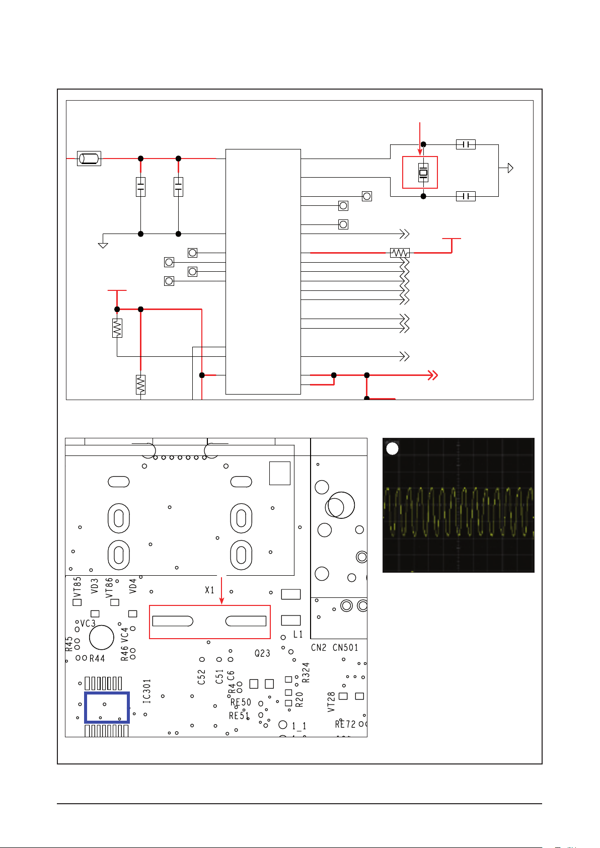
Check IC1 power input, X1
oscillation, Memory interface.
Refer to wave pattern
image of Fig. 4-7.
Change MAIN PCB.
Check if there is a
high signal from R2313?
Yes
HDMI Cable Error
No
Change MAIN PCB or System
MICOM.
4-12 Samsung Electronics
Page 43

NC
TX1M
TX0P
TX0M
TX2M
TX1P
TX2P
TXCP
TXCM
FD05015-19
1
10
11
12
13
2
3
4
5
6
7
8
9
MGND2
MGND4
0OHM
R624
0OHM
R625
0OHM
R628
0OHM
R629
0OHM
R631
0OHM
R632
5A5>
5A5>
5A5>
5A5>
5A5>
5A5>
0OHM
R634
0OHM
R637
LOPIVA16G05
12V
VT11
LOPIVA16G05
12V
VT14
12V
LOPIVA16G05
VT12
LOPIVA16G05
12V
VT15
LOPIVA16G05
12V
VT16
5A5>
5A5>
LOPIVA16G05
12V
VT18
12V
LOPIVA16G05
VT19
LOPIVA16G05
12V
VT17
LOPIVA16G05
12V
VT21
12V
LOPIVA16G05
VT20
DGND
NC
FD05015-19
0OHM
0OHM
0OHM
0OHM
0OHM
0OHM
0OHM
0OHM
LOPIVA16G05
12V
LOPIVA16G05
12V
12V
LOPIVA16G05
LOPIVA16G05
12V
LOPIVA16G05
12V
LOPIVA16G05
12V
12V
LOPIVA16G05
LOPIVA16G05
12V
LOPIVA16G05
12V
12V
LOPIVA16G05
DGND
R624
R625
R628
R629
R631
R632
R634
R637
VT11
VT14
VT12
VT15
VT16
VT18
VT19
VT17
VT21
VT20
5A5>
5A5>
5A5>
5A5>
5A5>
5A5>
5A5>
5A5>
TX1M
TX0P
TX0M
TX2M
TX1P
TX2P
TXCP
TXCM
1
10
11
12
13
2
3
4
5
6
7
8
9
MGND2
MGND4
1
Troubleshooting
HDMI TX, page 7-12
1
1
Samsung Electronics 4-13
1
MAIN PCB Top, page 6-9
<Fig. 4-6>
<HDMI EYE SIGNAL>
Page 44
Troubleshooting
D2.5V_PW
D3.3V_PW
D3.3V_PW
RESET_OUTB
BSC_S_SDA
BSC_S_SCL
EJTAG_TDI
EJTAG_TCK
EJTAG_TDO
EJTAG_TMS
EJTAG_TRSTB
CLK33_CLK
R90
10KOHM
R89
IC1
AA21
H16
H17
H18
H19
H20
H4
H7
J19
J20
J7
M7
P1
P2
P3
P4
P5
P7 R3
R4
R5R7
T6
U4
Y21
Y22
8F2<13E1<
7E6<
7E6<
7D6<
5000MA
0.01OHM
DGND
TP14TP13
6.3V
4.7UF
C153
TP16TP15
10V
100NF
C47
TP18
TP19
TP17
7D6<
10KOHM
R103
7D6<
7D6<
7D6<
7D3<
27MHZ
X1
50V
27PF
C52
27PF
50V
C51
DGND
OTP_V2P5
REG_OUT_2P5
RESET_OUTB
BSC_S_SDA
BSC_S_SCL
EJTAG_TDO
EJTAG_TDI
EJTAG_TMS
EJTAG_TCK
EJTAG_TRSTB
EJTAG_CE
CLK33_OUT
PLL_TESTOUT
BYP_216_CLK
BYP_SYS800_PLL
CLK27_XTALP
CLK27_XTALN
REG_VDD33
FP_4SEC_RESETB
RESETB
TEST_MODE3
TEST_MODE2
TEST_MODE1
TEST_MODE0
PLL_VSS
PLL_AVDD12
D3.3V_PW
D3.3V_PW
10KOHM
5000MA
0.01OHM
DGND
6.3V
4.7UF
10V
100NF
10KOHM
27MHZ
50V
27PF
27PF
50V
DGND
R90
R89
IC1
TP14TP13
C153
TP16TP15
C47
TP18
TP19
TP17
R103
X1
C52
C51
7E6<
7E6<
7D6<
7D6<
7D6<
7D6<
7D6<
7D3<
D2.5V_PW
RESET_OUTB
BSC_S_SDA
BSC_S_SCL
EJTAG_TDI
EJTAG_TCK
EJTAG_TDO
EJTAG_TMS
EJTAG_TRSTB
CLK33_CLK
AA21
H16
H17
H18
H19
H20
H4
H7
J19
J20
J7
M7
P1
P2
P3
P4
P5
P7 R3
R4
R5R7
T6
U4
Y21
Y22
OTP_V2P5
REG_OUT_2P5
RESET_OUTB
BSC_S_SDA
BSC_S_SCL
EJTAG_TDO
EJTAG_TDI
EJTAG_TMS
EJTAG_TCK
EJTAG_TRSTB
EJTAG_CE
CLK33_OUT
PLL_TESTOUT
BYP_216_CLK
BYP_SYS800_PLL
CLK27_XTALP
CLK27_XTALN
REG_VDD33
FP_4SEC_RESETB
RESETB
TEST_MODE3
TEST_MODE2
TEST_MODE1
TEST_MODE0
PLL_VSS
PLL_AVDD12
IC301
2
NAND FLASH / CLOCK / BBS / JTAG, page 7-13
2
2
4-14 Samsung Electronics
MAIN PCB Top, page 6-9
<Fig. 4-7>
<X1 Must be 27MHz>
Page 45

4-1-8 No Logo (Component) - Label C
B. No Logo (Component)
Troubleshooting
Video selection
accords with cable connection and
TV mode?
Yes
1
Video output from
C30, C31, C32?
Refer to wave pattern
Yes
image of Fig. 4-8.
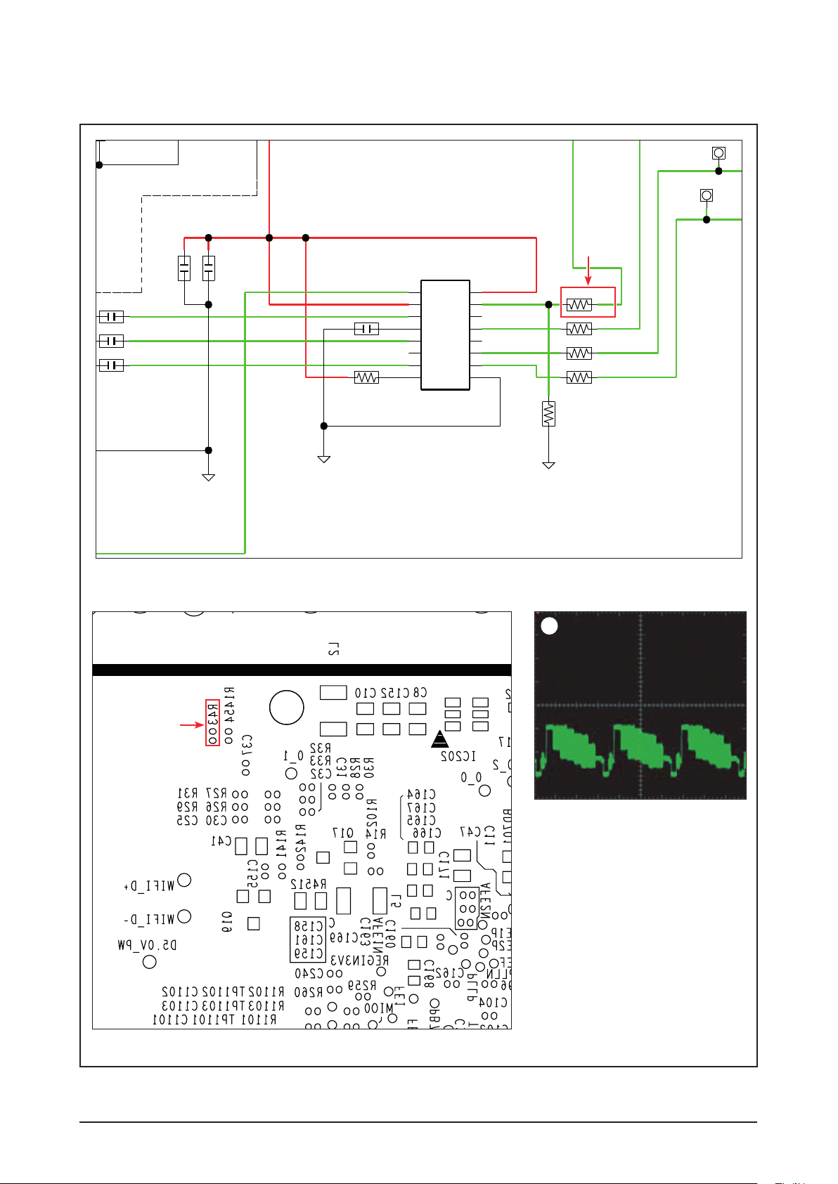
2
Video output from IC301?
IC301 Output Check
R44, R45, R46
No
No
No
Check the Video select, cable
connection, TV mode.
IC1 soldering error.
Change MAIN PCB.
Check peripheral IC301’s power,
soldering and devices.
Yes
Component Cable Error
Refer to wave pattern
image of Fig. 4-9.
Samsung Electronics 4-15
Page 46

Troubleshooting
1201-003013
D3.3V_PW
MI5V
R30
75OHM
R32
75OHM
R33
1UF
10V
C32
1UF
10V
C31
MMBT2222A
Q17
DGND
1UF
10V
C30
47KOHM
1/16W
R142
10UF
10V
C34
100NF
10V
C37
NC
R141
1UF
10V
C155
2.7UH
L5
NTR2101PT1G
Q19
0.01OHM
5000MA
R4512
10KOHM
R1455
10UF
10V
C41
MM1797DVBE
IC301
1
10
11
12
13
14
15
16
2
3
4
5
6
7
8 9
NC
R1454
75OHM
R46
75OHM
R45
75OHM
R44
75OHM
R43
DGND
FSA2257L10X
IC302
1
10
2
3
4
5
6
7
8
9
E
B
C
S
D
G
PBOUT
VCC2
CTRL
PRIN
PROUT
GND2
GND1
PBIN
VOUT
BIAS PYOUT
NC
NC
PYIN
VCC1
VIN
1S
1B1
GND
1B0
1A
VCC
2B1
2A
2S
2B0
1201-003013
75OHM
75OHM
1UF
10V
1UF
10V
MMBT2222A
DGND
1UF
10V
47KOHM
1/16W
10UF
10V
100NF
10V
NC
1UF
10V
2.7UH
NTR2101PT1G
0.01OHM
5000MA
10KOHM
10UF
10V
MM1797DVBE
NC
75OHM
75OHM
75OHM
75OHM
DGND
FSA2257L10X
R30
R32
R33
C32
C31
Q17
C30
R142
C34
C37
R141
C155
L5
Q19
R4512
R1455
C41
IC301
R1454
R46
R45
R44
R43
IC302
1
10
11
12
13
14
15
16
2
3
4
5
6
7
8 9
1
10
2
3
4
5
6
7
8
9
E
B
C
S
D
G
PBOUT
VCC2
CTRL
PRIN
PROUT
GND2
GND1
PBIN
VOUT
BIAS PYOUT
NC
NC
PYIN
VCC1
VIN
1S
1B1
GND
1B0
1A
VCC
2B1
2A
2S
2B0
1
1
C30 C31 C32
1 1 1
VIDEO / IPOD VIDEO, page 7-9
MAIN PCB Bottom, page 6-12
4-16 Samsung Electronics
<C30 Y Signal> <C31 Pb Signal> <C32 Pr Signal>
<Fig. 4-8>
Page 47

1201-003013
LINE_IN_R
LINE_IN_L
15E1<
15E1<
IPD_COMPOSITE
MI5V
COM_Y_DET
CVBS_DET
IPOD_VD_SW
100NF
10V
C37
10KOHM
R1455
10UF
10V
C41
MM1797DVBE
IC301
1
10
11
12
13
14
15
16
2
3
4
5
6
7
8 9
NC
R1454
75OHM
R46
75OHM
R45
75OHM
R44
75OHM
R43
PR
DGND
NC
VC4
100OHM
R8011
100OHM
1/16W
R8010
AR
DGND
FSA2257L10X
IC302
1
10
2
3
4
5
6
7
8
9
PB Y
9D4>
COM
NC
VC3
NC
VC2
NC
VC1
D
G
PBOUT
VCC2
CTRL
PRIN
PROUT
GND2
GND1
PBIN
VOUT
BIAS PYOUT
NC
NC
PYIN
VCC1
VIN
1S
1B1
GND
1B0
1A
VCC
2B1
2A
2S
2B0
1201-003013
100NF
10V
10KOHM
10UF
10V
MM1797DVBE
NC
75OHM
75OHM
75OHM
75OHM
DGND
NC
100OHM
100OHM
1/16W
DGND
FSA2257L10X
NC
NC
NC
C37
R1455
C41
IC301
R1454
R46
R45
R44
R43
PR
VC4
R8011
R8010
AR
IC302
PB Y
COM
VC3
VC2
VC1
15E1<
15E1<
9D4>
LINE_IN_R
LINE_IN_L
IPD_COMPOSITE
COM_Y_DET
CVBS_DET
IPOD_VD_SW
1
10
11
12
13
14
15
16
2
3
4
5
6
7
8 9
1
10
2
3
4
5
6
7
8
9
D
G
PBOUT
VCC2
CTRL
PRIN
PROUT
GND2
GND1
PBIN
VOUT
BIAS PYOUT
NC
NC
PYIN
VCC1
VIN
1S
1B1
GND
1B0
1A
VCC
2B1
2A
2S
2B0
IC301
2
Troubleshooting
2
2
2
R44 R45 R46
2 2 2
VIDEO / IPOD VIDEO, page 7-9
MAIN PCB Top, page 6-9
<R44 Y Signal> <R45 Pb Signal> <R46 Pr Signal>
Samsung Electronics 4-17
<Fig. 4-9>
Page 48

Troubleshooting
4-1-9 No Logo (Composite)
C. No Logo (Composite)
Video selection
accords with cable connection and
TV mode?
Yes
1
Video output from C25?
Yes
Refer to wave pattern
image of Fig. 4-10.
2
Video output from IC301 (R43)?
Yes
Refer to wave pattern
image of Fig. 4-11.
No
No
No
Check the Video select, cable
connection, TV mode.
IC1 soldering error.
Change MAIN PCB.
Check peripheral IC301’s power,
soldering and devices.
Component Cable Error.
4-18 Samsung Electronics
Page 49

NC
1201-003013
LINE_IN_R
LINE_IN_L
15E1<
15E1<
IPD_COMPOSITE
D3.3V_PW
MI5V
COM_Y_DET
CVBS_DET
IPOD_VD_SW
75OHM
R27
75OHM
R28
1/16W
1KOHM
R102
1UF
10V
C25
DGND
75OHM
R30
75OHM
R32
75OHM
R33
1UF
10V
C32
1UF
10V
C31
MMBT2222A
Q17
DGND
1UF
10V
C30
47KOHM
1/16W
R142
10UF
10V
C34
100NF
10V
C37
NC
R141
1UF
10V
C155
2.7UH
L5
NTR2101PT1G
Q19
0.01OHM
5000MA
R4512
DGND
10KOHM
R1455
10UF
10V
C41
MM1797DVBE
IC301
1
10
11
12
13
14
15
16
2
3
4
5
6
7
8 9
DGND
NC
R1454
75OHM
R46
75OHM
R45
75OHM
R44
75OHM
R43
PR
DGND
FSA2257L10X
IC302
1
10
2
3
4
5
6
7
8
9
PB Y
9D4>
COM
E
B
C
S
D
G
PBOUT
VCC2
CTRL
PRIN
PROUT
GND2
GND1
PBIN
VOUT
BIAS PYOUT
NC
NC
PYIN
VCC1
VIN
1S
1B1
GND
1B0
1A
VCC
2B1
2A
2S
2B0
NC
1201-003013
75OHM
75OHM
1/16W
1KOHM
1UF
10V
DGND
75OHM
75OHM
75OHM
1UF
10V
1UF
10V
MMBT2222A
DGND
1UF
10V
47KOHM
1/16W
10UF
10V
100NF
10V
NC
1UF
10V
2.7UH
NTR2101PT1G
0.01OHM
5000MA
DGND
10KOHM
10UF
10V
MM1797DVBE
DGND
NC
75OHM
75OHM
75OHM
75OHM
DGND
FSA2257L10X
R27
R28
R102
C25
R30
R32
R33
C32
C31
Q17
C30
R142
C34
C37
R141
C155
L5
Q19
R4512
R1455
C41
IC301
R1454
R46
R45
R44
R43
PR
IC302
PB Y
COM
15E1<
15E1<
9D4>
LINE_IN_R
LINE_IN_L
IPD_COMPOSITE
COM_Y_DET
CVBS_DET
IPOD_VD_SW
1
10
11
12
13
14
15
16
2
3
4
5
6
7
8 9
1
10
2
3
4
5
6
7
8
9
E
B
C
S
D
G
PBOUT
VCC2
CTRL
PRIN
PROUT
GND2
GND1
PBIN
VOUT
BIAS PYOUT
NC
NC
PYIN
VCC1
VIN
1S
1B1
GND
1B0
1A
VCC
2B1
2A
2S
2B0
1
Troubleshooting
1
VIDEO / IPOD VIDEO, page 7-9
1
C25
<C25 Composit Color Bar>
MAIN PCB Bottom, page 6-12
Samsung Electronics 4-19
<Fig. 4-10>
Page 50
Troubleshooting
1201-003013
LINE_IN_R
LINE_IN_L
15E1<
15E1<
IPD_COMPOSITE
MI5V
COM_Y_DET
CVBS_DET
IPOD_VD_SW
DGND
C32
C31
C30
10UF
10V
C34
100NF
10V
C37
1UF
10V
NTR2101PT1G
Q19
0.01OHM
5000MA
R4512
DGND
10KOHM
R1455
10UF
10V
C41
MM1797DVBE
IC301
1
10
11
12
13
14
15
16
2
3
4
5
6
7
8 9
DGND
NC
R1454
75OHM
R46
75OHM
R45
75OHM
R44
75OHM
R43
PR
DGND
VT85
DGND
NC
VC4
1/16W
100OHM
R8011
100OHM
1/16W
R8010
AR
AL
DGND
12V
LOPIVA16G05
VD3
12V
LOPIVA16G05
VD4
DGND
FSA2257L10X
IC302
1
10
2
3
4
5
6
7
8
9
PB Y
9D4>
COM
NC
VC3
NC
VC2
NC
VC1
12V
LOPIVA16G05
VD1
12V
LOPIVA16G05
VD2
S
D
G
PBOUT
VCC2
CTRL
PRIN
PROUT
GND2
GND1
PBIN
VOUT
BIAS PYOUT
NC
NC
PYIN
VCC1
VIN
1S
1B1
GND
1B0
1A
VCC
2B1
2A
2S
2B0
1201-003013
DGND
10UF
10V
100NF
10V
1UF
10V
NTR2101PT1G
0.01OHM
5000MA
DGND
10KOHM
10UF
10V
MM1797DVBE
DGND
NC
75OHM
75OHM
75OHM
75OHM
DGND
DGND
NC
1/16W
100OHM
100OHM
1/16W
DGND
12V
LOPIVA16G05
12V
LOPIVA16G05
DGND
FSA2257L10X
NC
NC
NC
12V
LOPIVA16G05
12V
LOPIVA16G05
C32
C31
C30
C34
C37
Q19
R4512
R1455
C41
IC301
R1454
R46
R45
R44
R43
PR
VT85
VC4
R8011
R8010
AR
AL
VD3
VD4
IC302
PB Y
COM
VC3
VC2
VC1
VD1
VD2
15E1<
15E1<
9D4>
LINE_IN_R
LINE_IN_L
IPD_COMPOSITE
COM_Y_DET
CVBS_DET
IPOD_VD_SW
1
10
11
12
13
14
15
16
2
3
4
5
6
7
8 9
1
10
2
3
4
5
6
7
8
9
S
D
G
PBOUT
VCC2
CTRL
PRIN
PROUT
GND2
GND1
PBIN
VOUT
BIAS PYOUT
NC
NC
PYIN
VCC1
VIN
1S
1B1
GND
1B0
1A
VCC
2B1
2A
2S
2B0
2
2
MAIN PCB Bottom, page 6-12
VIDEO / IPOD VIDEO, page 7-9
R43
2
<R43 Composit Output Color Bar>
4-20 Samsung Electronics
<Fig. 4-11>
Page 51

4-1-10 Disc skips or freezing
Disc skips or freezing
Troubleshooting
All Media
(BD/DVD/CD) NG?
Yes
Only BD NG?
No
No
Yes
Check the Power at
CN1601 (ST5.4V, D12V)?
Yes
Check the clock at
X1 27MHz?
Yes
Change the MAIN PCB.
Q13 Emitter
Voltage check
Q12: DVD, Q11:CD
4V ~ 6.5V?
Yes
No
SMPS Check (refer 4-1p)
No
Check IC1’s phreperial part
like soldering etc.
No
Change the DECK.
No
Change the DECK.Change the MAIN PCB.
Only DVD NG?
No
Only CD NG?
No
Change the MAIN PCB
Yes
RFP Check?
Signal level OK?
BD: over 400mV
DVD: over 200mV
CD: over 200mV
Yes
Yes
Samsung Electronics 4-21
Page 52

Troubleshooting
4-1-11 No Disc Reading Error
No Disc Reading Error
Is this issue happen with
only specific Blu-ray Disc title?
Yes
Does the unit contain the latest firmware
available on the Samsung Web Site?
Yes
Update with the new version and
try
again.
No
No
Refer to ‘Disc Loading Error’.
Consuit with the Samsung Electronics.
4-22 Samsung Electronics
Page 53

4-1-12 Network Error
Network Error
Troubleshooting
Cable connection
between Set & LAN ok?
Yes
Check Network connection
Test in the setup menu?
OK
Change the MAIN PCB.
No
Fail
Correctly connect the cable
or wireless jack.
Refer User Manual's Network Setup
Part and reset-up setting of Network.
The connection between LAN and SET is direct. So there is no need to check H/W if there is network problem.
If it is, the problem is MAIN CHIP(IC1)'s BGA soldering problem.
It must be changed to new board.
Samsung Electronics 4-23
Page 54

Troubleshooting
4-2 Initialization & Upgrade Methods
4-2-1 How to check F/W version
Method 1
- Step 1: Open the tray.
- Step 2: Press and hold “INFO” button on the
remote for 5 seconds.
- After that, the TV Display should look similar to
Fig. 4-12.
Method 2
- Press “MENU” on the remote control
- Setup→SystemSetup→SystemInformation
Explanation of F/W Terms
- S/W : BACKEND Firmware
- Front : System micom
- Loader : Loader Firmware
- DSP : DSP firmware CEC : CEC firmware
- Region : BD region code / DVD region code
- Macrovision : Macrovision version
- Model : Model name
- ESN : Netflix serial number
- BD/DVD Adjust : Loader Disc Adjust (only factory possible)
S/W : HTB-C5500USC_0014
Front : HTB-C5500WM_0001
Loader : HTB-C5500WWL_1.00
DSP : 00/00/012 CEC : 02/15/32
Region : A/1 (BD/DVD)
Macrovision : BBS61
Model : HTB-C55xxUS
ESN-SSBCD__________________________
BD/DVD Adjust : OK
<Fig. 4-12>
4-24 Samsung Electronics
Page 55

Troubleshooting
Display
Audio
System
Network
Language
Security
General
Support
Settings
Software Upgrade
Disc Menu :
Audio :
Subtitle :
Software Upgrade
Current Version : XXX-XXXXXXXXX
By Internet
►
Auto Upgrade Notification
: On
SelectReturn
4-2-2 How to update firmware
This menu allows you to upgrade software in order to improve the performance of the unit or to acquire additional
services. In addition, you can also check the current software version, update via Internet, and set the Auto
upgrade notification by using this menu. If the product is properly connected to the network via cable or wireless,
then it will automatically connect to our website each time it is turned on and will download files in order to update
itself.
1. To select By Internet, press the “ENTER” button.
You will be noticed with a popup message if it finds a
software program to update.
2. If you select Yes, it will turn off automatically before
restarting. (Never turn it on manually.)
3. The update progress popup will appear.
When the update is completed, it will turn back off
automatically.
4. Press the “POWER” button to turn on the product.
[Note]
Update will be completed when the product turns off after two times of restarting. Press the POWER button to
turn on the updated product for your use.
Never turn off or on the product manually during the update process.
Samsung Electronics shall take no legal responsibility for product malfunction caused by an unstable Internet
connection or consumer negligence during software upgrade.
You can update software in any of the two ways as follows : Software update is the same as in the By Internet
●USB:Visitwww.samsung.com/bluraysupport,thendownloadandstorethelatestsoftware(RUFfile)intothe
USB flash drive. Connect the USB flash drive to the USB port of the product (disc tray must be empty) to
update the software, then follow the on-screen instructions.
●CD/DVD:Visitwww.samsung.com/bluraysupport,downloadandwritethelatestsoftware(RUFfile)ontoadisc.
[Note]
If you want to cancel the upgrade in the process of downloading the upgrade data, press the ENTER button.
When the system upgrade is done, check the software details in the software Upgrade menu.
Do not turn off the product during the System Upgrade, as it may cause the product to not work properly.
Do not use USB devices other than USB Flash Drives to do software upgrades using the USB Host jack.
Samsung Electronics 4-25
menu.
Insert and play the disc in the product to start the update, then follow the on-screen instructions.
Page 56

Troubleshooting
4-2-3 Cold Start Method (Initialize Setup)
1. This is useful when one forgets their Parental Lock password.
2. Press “
3. Then,VFDsign:‘Initialize’→Powerwillbeturnedoffautomatically.
4. System Micom Cold Start
During Stand-By, just press the Stop Button on the Remote Control for 5 seconds.
Then, the Red LED should blink.
” button on the front panel for over 5 seconds during the ‘no disc’ status.
4-26 Samsung Electronics
Page 57

4-3 Buyer-Region Code Setting Method
4-3-1 Inserting Region Code after replacing the Main PBA
[Reference]
- After replacing the Main PBA and System Micom (IC1302), the region code should be inserted.
- The unit will not work properly if you do not insert the correct region code.
- You must use the remote control.
1. Press the “TUNER MEMORY” button on the remote control for 4-5
seconds
Troubleshooting
2. After step (1), you should see the “T-MODE” message display on
the VFD. Press the “down” direction button during this message.
The “T-MODE” indicator on the VFD only appears for a very
short time.
3. Afterstep(2),youcansee“TEST−−−”ontheVFD.
Insert the number “46” to select the Region Code.
2
1
T-MODE
TEST − − −
4. Afterstep(3),youcansee“−−−”ontheVFD.
Insert the Region Code (see Table on next page) corresponding to
the model and area in which you reside in using the “0-9” buttons on
the remote control.
Samsung Electronics 4-27
− − −
Page 58

Troubleshooting
HT-C5200 Series 2.1CH Option Table
Area
HT-C5200 Series 2.1CH
Region Code
USA 040
Japan 041
Korea 042
Taiwan 043
Philippines 044
Mexico 045
Latin American 046
Europe 047
Indonesia 048
Australia 049
Russia (semi_mic) 050
Russia (full_mic) 051
Africa 052
Remark
Only models which support semi-karaoke not
including MIDI file.
Full karaoke models which support MIDI file.
China (semi_mic) 053
Brazil 054
Canada 055
ETC 056
ETC 057
ETC 058
ETC 059
<Table 4-1>
4-28 Samsung Electronics
Page 59

MEMO
Samsung Electronics 4-29
Page 60

5-1 Samsung Electronics
Exploded View & Part List
This Document can not be used without Samsung’s authorization.
AS078
C011
F001
FD23
FL261
AS102
HKF01
MK01A
FL261
ES19
AD330
D001A
AD340
P001A
MA01A
T0268
T001
M0014
FL06
AD504
FL06
AF020
EF01
FL261
W275
W275
W392
W392
W384
W275
W392
MF01A
W275
CC02
W384
W392
W392
W275
FK01A
5. Exploded View & Part List
5-1 Product Exploded View
Page 61

Exploded View & Part List
Part List
Loc. No. Part No. Description;Specification Qty. SNA Remark
AD330 AH64-05292B DECORATION-SIDE-L;HT-C5500,ABS,2.5,350,5 1 SNA
AD340 AH64-05293B DECORATION-SIDE-R;HT-C5500,ABS,2.5,350,5 1 SNA
AD504 AH64-05321B DOOR-HIDDEN;HT-C5500,ABS+PMMA,2.2,25,80, 1 SNA
AF020 AH63-02108A FILTER-VFD;HT-C5500,PC,0.5T,90,25,VIOLET 1 SNA
AS078 AH63-02006A SHEET-FUNCTION;HT-BD3250,PC T0.3,0.3,156 1 SNA
AS102 AH63-02007A SHEET-POWER;HT-BD3250,PC T0.3,0.3,100,15 1 SNA
C011 AH61-02527A SPRING ETC-DOOR;HT-Z310,STS 304 WPS,0.2, 1 SA
CC02 AH64-05291F CHASSIS-BOTTOM;HT-C5500,EGI-SECC,0.8,430 1 SNA
D001A AK96-01214J ASSY ENGINE P-BD DECK;BD-P6C,OEM,1B 1 SNA
EF01 3103-001251 FAN-DC;12,80mA,2000rpm,0.11m^3/mi,0.62mm 1 SA
ES19 AH61-03102A SPRING ETC-HIDDEN;HT-C6500,STAINLESS-STS 1 SA
F001 AH63-02130A COVER-FRONT;HT-C5500,ABS+PMMA,2.2,430,80 1 SNA
FD23 AH64-05320A DOOR-BD;HT-C5500,ABS+PMMA,2.2,15,100,3,B 1 SA
FK01A AH96-00175B ASSY KNOB P-VOLUME;HT-C5500,BASIC,PMMA+A 1 SNA
FL06 3809-002517 FFC CABLE-FLAT;30V,80C,100mm,28P,1.0mm,U 1 SA
FL06 3809-002518 FFC CABLE-FLAT;30V,80C,220mm,28P,1.0mm,U 1 SA
FL261 3809-002351 FFC CABLE-FLAT;30V,80C,185mm,5P,1.0mm,UL 1 SA
FL261 3809-002357 FFC CABLE-FLAT;30V,80C,90mm,15P,1.0mm,UL 1 SA
FL261 3809-002359 FFC CABLE-FLAT;30V,80C,45mm,5P,1mm,UL206 1 SA
HKF01 AH61-02963A HOLDER-KEY FUNCTION;HT-BD3250,ABS,13,60, 1 SNA
M0014 AH94-02433F ASSY PCB MAIN;HT-C5500,BD HOME THEATER,E 1 SA
MA01A AH94-02430B ASSY PCB AMP;HT-C5500,BD HOME THEATER,EP 1 SA
MF01A AH94-02431C ASSY PCB FRONT;HT-C5200,BD HOME THEATER, 1 SA
MK01A AH94-02432B ASSY PCB KEY;HT-C5500,BD HOME THEATER,FR 1 SNA
P001A AH94-02449D ASSY PCB SMPS;HT-C5500_220V,BD HTS,1 1 SA
T001 AH63-02119B COVER-TOP;HT-C5500,ABS,2.5,350,58,BLK 1 SA
T0268 3903-000403 CBF-POWER CORD;AT,EU,CP2,HOUSING(2P),250 1 SA
W275 6003-001561 SCREW-TAPTYPE;BH,+,-,B,M3,L6,ZPC(WHT),SW 14 SA
W384 6002-000126 SCREW-TAPPING;FH,+,-,2S,M3,L10,ZPC(BLK), 2 SA
W392 6003-000282 SCREW-TAPTYPE;BH,+,-,B,M3,L8,ZPC(BLK),SW 16 SA
Samsung Electronics 5-2
This Document can not be used without Samsung’s authorization.
Page 62

5-3 Samsung Electronics
Exploded View & Part List
This Document can not be used without Samsung’s authorization.
W012
H500
H110
H100
H300
PICKUP
W012
W350
W012
BSF01
H400
Transparency Color
W381
H400
Black Color
FL346
FFD01
5-2 DECK Exploded View
Page 63

Exploded View & Part List
Part List
Loc. No. Code No. Description;Specification Qty. SNA Remark
BSF01 AK61-00985A BRACKET-SHAFT FIX R;BD-P6,SUS 301 CSP,T0.35 2 SA
FFD01 AK41-00931A FFC-DECK;BD-C5500,A TYPE,PITCH 1.0,22P,T0.11,L 1 SA
FL346 AK41-00930A FFC-PU;BD-C5500,B TYPE,PITCH0.5,40P,T0.11,L250* 1 SA
H100 AK96-01219A ASSY BRACKET P-TRAVERSE DECK;BD-P6,BRKT 1 SA
H110 AK96-01220A ASSY FRAME P-MAIN;BD-P6,FRAME+GEAR+PCB 1 SA
H300 AK96-01216A ASSY HINGE P-PU;BD-P6,POM+SPRING 1 SA
H400
AK96-01217A ASSY COVER P-UPPER;BD-P6,COVER UPPER + 1 SA Black
AK96-01217B ASSY COVER P-UPPER;BD-P6,COVER UPPER + 1 SA
H500 AK63-00606A COVER-BOTTOM;BD-P6,EGI-SECC,TO.5 1 SA
AK96-01213A ASSY PICK UP P;SOH-BP6 1 SA
AK96-01236A ASSY PICK UP P;SOH-BP6 1 SA
PICKUP
AK96-01239A ASSY PICK UP P;SOH-BP6 1 SA
AK96-01244A ASSY PICK UP P;SOH-BP6 1 SA
W012 6002-001086 SCREW-TAPPING;PH,+,B,M1.7,L5.0,ZPC(WHT) 6 SA
W350 6001-001003 SCREW-MACHINE;BH,+,M2.6,L6,ZPC(BLK) 4 SA
W381 6003-001449 SCREW-TAPTYPE;BH,+,B,M2.6,L6,NI PLT,SWRCH18A 2 SA
Transparency
Samsung Electronics 5-4
This Document can not be used without Samsung’s authorization.
Page 64

5-5 Samsung Electronics
Exploded View & Part List
This Document can not be used without Samsung’s authorization.
SPEAKER IMPEDANCE : 3
FMANT.
iPod
SPEAKER IMPEDANCE : 3
FMANT.
iPod
SPEAKER IMPEDANCE : 3
5-3 Speaker System
Front
Speaker (R)
Front
Speaker (L)
Subwoofer
Part List
Loc. No. Code No. Description;Specification Qty. SNA Remark
Front Speaker (L)
Front Speaker (R)
Subwoofer
AH81-06192A SPEAKER-FRONT LEFT; PS-C5200
AH81-06192B SPEAKER-FRONT RIGHT; PS-C5200
AH81-00625A SPEAKER-SUBWOOFER; PS-C5200
1 SA
1 SA
1 SA
Page 65

Exploded View & Part List
5-4 Electrical Part List
Loc. No. Part No. Description Specification Qty. SNA Remark
MA01A AH94-02430B ASSY PCB AMP HT-C5500,BD HOME THEATER,EP 1 SA
6MC22 2203-000975 C-CER,CHIP 47nF,10%,25V,X7R,TP,1608,- 1 SNA
AAC1 2203-005249 C-CER,CHIP 100nF,10%,50V,X7R,TP,1608 71 SNA
AAR39 2007-000123 R-CHIP 1.5Kohm,5%,1/10W,TP,1608 1 SA
AC10 2203-000531 C-CER,CHIP 2.7nF,10%,50V,X7R,1608 6 SNA
AC139 2203-000491 C-CER,CHIP 2.2nF,10%,50V,X7R,1608 3 SA
AC510 3708-001981 CONNECTOR-FPC/FFC/PIC 28P,1mm,SMD-S,SN,N 1 SNA
AD480 2203-000203 C-CER,CHIP 100nF,10%,16V,X7R,TP,2012,2mm 2 SA
AD480 2203-001386 C-CER,CHIP 100nF,10%,100V,X7R,TP,3216,3. 4 SNA
AD480 2203-006336 C-CER,CHIP 10000nF,10%,25V,X5R,3216 9 SA
AD480 2203-006698 C-CER,CHIP 1000nF,10%,25V,X7R,1608 2 SNA
AD480 2203-006706 C-CER,CHIP 2200nF,10%,50V,X7R,3225 1 SNA
AD480 2203-007176 C-CER,CHIP 10000nF,10%,16V,X5R,TP,2012 ( 14 SNA
AH025 AH62-00223A HEAT SINK-AMP HT-C5500,ALLUMINUM,3T,100, 1 SNA
AH260 AH61-02854A HOLDER-HEATSINK HT-BD1250,HIPS V0,2.0mm, 2 SNA
AQ7 0504-000128 TR-DIGITAL FJV3103R,NPN,200mW,22K/22Kohm 1 SA
AR108 2007-000097 R-CHIP 47Kohm,5%,1/10W,TP,1608 15 SA
AR150 2007-000078 R-CHIP 1Kohm,5%,1/10W,TP,1608 9 SA
AR158 2007-000077 R-CHIP 470ohm,5%,1/10W,TP,1608 1 SA
AR174 2007-000129 R-CHIP 27Kohm,5%,1/10W,TP,1608 5 SA
AR30 2007-000074 R-CHIP 100ohm,5%,1/10W,TP,1608 5 SA
AR42 2007-000939 R-CHIP 47Kohm,1%,1/10W,TP,1608 3 SA
ARR2 2007-000102 R-CHIP 100Kohm,5%,1/10W,TP,1608 1 SA
C 2402-000108 C-AL,SMD 10uF,20%,16V,WT,TP,4.3x4.3x5.2m 3 SA
C 2402-001218 C-AL,SMD 22UF,20%,35V,WT,TP,6.6X6.6X5.8M 2 SA
C 2401-004106 C-AL 680uF,20%,50V,-,BK,12.5 x 35,5 6 SNA
C125 2203-006361 C-CER,CHIP 10000nF,10%,10V,X5R,TP,2012 5 SC
C134 2203-000257 C-CER,CHIP 10nF,10%,50V,X7R,TP,1608 2 SA
C24 2203-005565 C-CER,CHIP 1nF,5%,50V,NP0,TP,1608 9 SA
C4N08 2203-000140 C-CER,CHIP 1.5nF,10%,50V,X7R,1608 3 SNA
CER02 2007-000071 R-CHIP 22ohm,5%,1/10W,TP,1608 1 SA
CER04 2007-000084 R-CHIP 4.7Kohm,5%,1/10W,TP,1608 1 SA
D0254 0402-001090 DIODE-SCHOTTKY MBRS1100,100V,1000MA,DO-2 1 SNA
D1 0401-001099 DIODE-SWITCHING 1N4148WS,75V,150mA,SOD-3 5 SA
DR01A 0402-001427 DIODE-RECTIFIER ES1D,200V,1A,DO-214AC,TP 3 SA
DR01A 0402-001614 DIODE-RECTIFIER S1G,400V,1A,DO-214AC,TP 6 SA
DR1 2007-000043 R-CHIP 1Kohm,1%,1/10W,TP,1608 3 SA
DS01A 0401-001166 DIODE-SWITCHING BAV20WS-V,150V,250mA,SOD 3 SA
ER19 2007-002899 R-CHIP 10ohm,1%,1/10W,TP,1608 4 SA
FAN1 3711-000820 HEADER-BOARD TO CABLE BOX,2P,1R,2.5MM,ST 1 SA
FAR22 2007-000082 R-CHIP 3.3Kohm,5%,1/10W,TP,1608 1 SNA
FD7 0601-001226 LED SMD(TOP VIEW),RED,1.2x0.8mm,660nm,1. 7 SNA
FL06 3809-002517 FFC CABLE-FLAT 30V,80C,100mm,28P,1.0mm,U 1 SA
FMR4 2007-000080 R-CHIP 2Kohm,5%,1/10W,TP,1608 6 SNA
HR13 2007-000821 R-CHIP 390ohm,1%,1/10W,TP,1608 3 SNA
IDR23 2007-000116 R-CHIP 120ohm,5%,1/10W,TP,1608 1 SNA
JP19 2007-000033 R-CHIP 0ohm,5%,1/4W,TP,3216 6 SA
KAC5 2203-001126 C-CER,CHIP 0.68nF,10%,50V,X7R,1608 6 SNA
Samsung Electronics 5-6
This Document can not be used without Samsung’s authorization.
Page 66

5-7 Samsung Electronics
Exploded View & Part List
This Document can not be used without Samsung’s authorization.
Loc. No. Part No. Description Specification Qty. SNA Remark
KAR13 2007-000060 R-CHIP 100Kohm,1%,1/10W,TP,1608 3 SNA
KAR21 2007-000070 R-CHIP 0ohm,5%,1/10W,TP,1608 10 SA
KAR7 2007-000120 R-CHIP 680ohm,5%,1/10W,TP,1608 6 SNA
KOP1 1201-000163 IC-OP AMP 4560,SOP,8P,173MIL,DUAL,100V/m 2 SA
KQ1 0501-000279 TR-SMALL SIGNAL KSA1182-Y,PNP,150mW,SOT- 2 SA
KQ6 0501-000341 TR-SMALL SIGNAL KSC1623-L,NPN,200mW,SOT- 1 SA
MC111 2203-000646 C-CER,CHIP 0.024nF,5%,50V,C0G,TP,1608 2 SNA
MIC10 0801-002391 IC-CMOS LOGIC 74LCX00,NAND GATE,TSSOP,14 2 SNA
MR112 2007-000309 R-CHIP 10ohm,5%,1/10W,TP,1608 14 SA
MR122 2007-000094 R-CHIP 22Kohm,5%,1/10W,TP,1608 7 SA
MR19 2007-000087 R-CHIP 6.8Kohm,5%,1/10W,TP,1608 8 SA
MR2 2007-000130 R-CHIP 39Kohm,5%,1/10W,TP,1608 3 SA
MR9 2007-000127 R-CHIP 9.1Kohm,5%,1/10W,TP,1608 6 SNA
MROP1 2007-000090 R-CHIP 10Kohm,5%,1/10W,TP,1608 23 SA
ND51C2 2007-000066 R-CHIP 20Kohm,1%,1/10W,TP,1608 3 SNA
P803T 1404-001483 THERMISTOR-PTC 470ohm,50%,32V,TP 2 SA
PC69 2203-006818 C-CER,CHIP 47000nF,20%,6.3V,X5R,3216 3 SA
PCW2 3711-003359 HEADER-BOARD TO CABLE BOX,10P,1R,2.5mm,S 1 SA
PPD1 0402-000309 DIODE-RECTIFIER 1SR154-400,400V,1A,SOD-1 1 SA
PR4 2007-000052 R-CHIP 10Kohm,1%,1/10W,TP,1608 3 SA
PR6 2007-000072 R-CHIP 47ohm,5%,1/10W,TP,1608 18 SNA
PR6 2007-000583 R-CHIP 22Kohm,1%,1/10W,TP,1608 2 SA
Q1 0501-000479 TR-SMALL SIGNAL KST42,NPN,350mW,SOT-23,T 5 SA
Q1040 0501-000457 TR-SMALL SIGNAL MMBT2222A/KST2222A,NPN,3 2 SA
Q301 0501-000481 TR-SMALL SIGNAL KST92,PNP,350mW,SOT-23,T 3 SA
Q409 0505-002365 FET-SILICON IRF6645,N,100V,5.7A,0.035ohm 6 SNA
R1 2007-002425 R-CHIP 1ohm,5%,1/10W,TP,1608 6 SNA
R15 2007-000134 R-CHIP 33Kohm,5%,1/10W,TP,1608 3 SNA
R1P151 2007-000121 R-CHIP 820ohm,5%,1/10W,TP,1608 3 SA
R1S36 2007-000491 R-CHIP 2.2Kohm,1%,1/10W,TP,1608 3 SA
R227 2007-000086 R-CHIP 5.6Kohm,5%,1/10W,TP,1608 1 SA
R319 2007-000143 R-CHIP 4.7Kohm,5%,1/16W,TP,1005 1 SNA
R419 2007-000882 R-CHIP 4.7ohm,5%,1/10W,TP,1608 2 SA
R505 2007-000496 R-CHIP 2.2Kohm,5%,1/4W,TP,3216 3 SA
R509 2007-001179 R-CHIP 8.2Kohm,5%,1/10W,TP,1608 2 SA
R510 2007-000108 R-CHIP 510Kohm,5%,1/10W,TP,1608 1 SA
R893B 2007-000122 R-CHIP 1.2Kohm,5%,1/10W,TP,1608 6 SA
RR2 2007-000075 R-CHIP 220ohm,5%,1/10W,TP,1608 1 SA
T0052 2703-002524 INDUCTOR-SMD 10uH,10%,3225 2 SNA
T0052 2703-003768 INDUCTOR-SMD 330uH,20%,6060 1 SNA
T0081 6001-000571 SCREW-MACHINE PH,+,-,M3,L8,ZPC(WHT),SWRC 2 SNA
T0087 1203-002835 IC-POSI.FIXED REG. KIA7805AF,DPAK,3P,6.6 1 SA
T0415 3716-001243 TERMINAL-BLOCK WIRE TYPE,12P,14mm,0V,0A 1 SA
T0568 3301-001404 BEAD-SMD 30ohm,2012,TP,15.9OHM/30MHz 4 SA
WC31 2305-000407 C-FILM,LEAD-PEF 470nF,5%,100V,TP,10.5x6x 3 SA
X202 2801-004371 CRYSTAL-SMD 12.288MHz,50ppm,SX-1,18pF,50 1 SNA
ZR24 2007-000109 R-CHIP 1Mohm,5%,1/10W,TP,1608 1 SA
ZVL3 3301-001495 BEAD-SMD 120ohm,2012,2500mA,TP,115ohm/10 2 SA
Page 67

Exploded View & Part List
Loc. No. Part No. Description Specification Qty. SNA Remark
0103-007285 RESIN-PC BK0007,2.0 V2,PC/GF20%,Glass fi 2 SNA
0202-001463 SOLDER-WIRE LFC2-W3.0,-,D3,99.79Sn/0.2Cu 6.171 SNA
0202-001477 SOLDER-CREAM LST309-M,D20~45um,96.5Sn/3A 2.38 SNA
0202-001608 SOLDER-WIRE FLUX LFC7-107,D0.8,99.3Sn/0. 0.167 SNA
0204-002420 SOLVENT 1M-1000,C3H70H,96 3.25 SNA
0204-002607 FLUX DF-234U,13%,14KG,Gravity 0.82 2.52 SNA
0403-001441 DIODE-ZENER MMSZ5239B,5%,500MW,SOD-123,T 2 SA
0403-001483 DIODE-ZENER UDZS18B,17.56-18.35V,200mW,S 2 SA
0501-000150 TR-SMALL SIGNAL 2SA1037,PNP,200mW,SOT-23 1 SA
0504-000105 TR-DIGITAL DTA114EU,PNP,200MW,10K/10K,SC 1 SA
1003-002268 IC-GATE DRIVER IRS2053MTRPBF,MLPQ,48P,7X 1 SA
1203-006105 IC-DC/DC CONVERTER MAX5033DUSA,SO,8P,4.9 1 SNA
1203-006107 IC-NEGA.FIXED REG. KIA7905F,DPAK,3P,6.6x 1 SNA
1204-002968 IC-MODULATOR PS9830B,TQFP,100P,14x14mm,P 1 SA
2007-000253 R-CHIP 1.5ohm,5%,1/4W,TP,3216 2 SA
2007-000464 R-CHIP 18ohm,5%,1/4W,TP,3216 1 SA
2007-000819 R-CHIP 390Kohm,5%,1/10W,TP,1608 1 SA
2007-001300 R-CHIP 56ohm,5%,1/2W,TP,5025 1 SNA
2007-007065 R-CHIP 10ohm,5%,1W,TP,6432 3 SA
2007-007625 R-CHIP 0ohm,5%,1W,TP,6432 1 SA
2007-007723 R-CHIP 75Kohm,1%,1/10W,TP,1608 1 SA
2007-007750 R-CHIP 39ohm,1%,1W,TP,6432 1 SNA
2301-001760 C-FILM,MPEF 100nF,10%,250V,TP,B5xH13.5x1 3 SA
AH27-00081A COIL FILTER DBF-16A18(OFC),18.2uH,30mohm 3 SNA
AH41-01302B PCB-AMP HT-C5500,FR-4,2,02,T1.6,143x158, 1 SNA
AH63-02106B SHEET-THERMAL_IC HT-C5500,GAP PAD,2T,80, 1 SNA
AH97-04331A ASSY AUTO BD HOME THEATER,5500 AMP PCB A 1 SNA
AH97-04332A ASSY SMD BD HOME THEATER,ASSY SMD 5500 A 1 SNA
AH97-04333A ASSY MANUAL INSERT HT-C5500,ASSY MANUAL 1 SNA
M0014 AH94-02433F ASSY PCB MAIN HT-C5500,BD HOME THEATER,E 1 SA
AAC1 2203-005249 C-CER,CHIP 100nF,10%,50V,X7R,TP,1608 12 SNA
AAC14 2203-000888 C-CER,CHIP 4.7nF,10%,50V,X7R,TP,1608 2 SA
AC109 2203-000783 C-CER,CHIP 0.33nF,5%,50V,C0G,1608 2 SA
AC510 3708-001436 CONNECTOR-FPC/FFC/PIC 4P,1mm,SMD-S,SN,N 1 SA
AC510 3708-001935 CONNECTOR-FPC/FFC/PIC 40P,0.5mm,SMD-S,AU 1 SNA
AC510 3708-001981 CONNECTOR-FPC/FFC/PIC 28P,1mm,SMD-S,SN,N 2 SNA
AC510 3708-002603 CONNECTOR-FPC/FFC/PIC 22P,1mm,SMD-S,SN,N 1 SNA
AC510 3708-002619 CONNECTOR-FPC/FFC/PIC 13P,1.0MM,SMD-S,SN 1 SNA
AD480 2203-000585 C-CER,CHIP 0.22nF,10%,50V,X7R,1005 1 SA
AD480 2203-000679 C-CER,CHIP 0.027nF,5%,50V,C0G,1005 2 SA
AD480 2203-002994 C-CER,CHIP 0.068nF,5%,50V,CH,BK,1005 4 SNA
AD480 2203-005659 C-CER,CHIP 0.18nF,5%,50V,NP0,1005 1 SNA
AD480 2203-006336 C-CER,CHIP 10000nF,10%,25V,X5R,3216 11 SA
AD480 2203-006824 C-CER,CHIP 4700nF,10%,10V,X5R,1608 8 SNA
AHR41 2007-001175 R-CHIP 8.2Kohm,1%,1/10W,TP,1608 1 SA
AIC2 1002-001558 IC-A/D CONVERTER AK5367,24,VSOP,30P,9.7x 1 SA
AQ7 0504-000128 TR-DIGITAL FJV3103R,NPN,200mW,22K/22Kohm 2 SA
AR108 2007-000097 R-CHIP 47Kohm,5%,1/10W,TP,1608 1 SA
Samsung Electronics 5-8
This Document can not be used without Samsung’s authorization.
Page 68

5-9 Samsung Electronics
Exploded View & Part List
This Document can not be used without Samsung’s authorization.
Loc. No. Part No. Description Specification Qty. SNA Remark
AR161 2007-001167 R-CHIP 75ohm,5%,1/10W,TP,1608 7 SNA
AR28 2007-000683 R-CHIP 3.3Kohm,1%,1/10W,TP,1608 1 SA
AR30 2007-001306 R-CHIP 150ohm,5%,1/16W,TP,1005 1 SA
AR48 2007-000431 R-CHIP 16Kohm,5%,1/10W,TP,1608 2 SA
AR49 2007-000140 R-CHIP 1Kohm,5%,1/16W,TP,1005 33 SNA
AR61 2007-000869 R-CHIP 4.7Kohm,1%,1/10W,TP,1608 1 SA
AS503 AH63-02117B SHEET-LENS SWA-5000,PC,0.5T 1 SNA
AVC08 2203-002398 C-CER,CHIP 22nF,10%,50V,X7R,1608 1 SNA
AVR73 2007-000142 R-CHIP 2.7Kohm,5%,1/16W,TP,1005 3 SNA
C 2402-000108 C-AL,SMD 10uF,20%,16V,WT,TP,4.3x4.3x5.2m 2 SA
C 2402-001160 C-AL,SMD 330UF,20%,16V,WT,TP,1008 3 SA
C102 2203-006158 C-CER,CHIP 100nF,10%,16V,X7R,1005 84 SNA
C125 2203-006361 C-CER,CHIP 10000nF,10%,10V,X5R,TP,2012 79 SC
C134 2203-000257 C-CER,CHIP 10nF,10%,50V,X7R,TP,1608 1 SA
C151 2203-003039 C-CER,CHIP 0.008nF,0.25pF,50V,C0G,TP,100 1 SNA
C234 2203-006378 C-CER,CHIP 4700nF,10%,6.3V,X5R,TP,1608 1 SNA
C239 2203-006047 C-CER,CHIP 33nF,10%,16V,X7R,1005 6 SA
C254 2203-000438 C-CER,CHIP 1nF,10%,50V,X7R,TP,1005 13 SA
C3 2203-000384 C-CER,CHIP 0.015nF,5%,50V,C0G,1608 4 SNA
C33 2203-002687 C-CER,CHIP 1.2nF,10%,50V,X7R,TP,1005 3 SA
C510 2203-006170 C-CER,CHIP 220nF,10%,16V,X7R,1608 2 SNA
C600 2203-006090 C-CER,CHIP 10000nF,10%,6.3V,X5R,TP,2012 6 SA
C637 2203-001656 C-CER,CHIP 0.47nF,5%,50V,NP0,1608 4 SNA
C802 2203-006348 C-CER,CHIP 1000nF,10%,25V,X5R,TP,1608 1 SA
CEIC1 AK09-00159A IC MICOM MC80C0316-MC015 D32,44,2.7~5.5, 1 SNA
CEQ2 0505-000110 FET-SILICON 2N7002,N,60V,115mA,7.5ohm,0. 1 SA
CER42 2007-000999 R-CHIP 510ohm,1%,1/10W,TP,1608 1 SA
CIS3 AH40-00156A TUNER TT-705FM/RDS,MAX-DG35,FM. RDS,75 o 1 SA
CON2 3722-002730 JACK-MODULAR 6P/4P,USB+LAN,ANGLE,N,AU 1 SNA
CQ3 0501-002184 TR-SMALL SIGNAL KTD1304,NPN,200mW,SOT-23 3 SA
D0254 0404-000002 DIODE-SCHOTTKY CMPSH-3,30V,100mA,SOT-23, 5 SA
D0254 0404-001006 DIODE-SCHOTTKY RB751V,40V,30mA,SOD-323,T 1 SA
D1 0401-001099 DIODE-SWITCHING 1N4148WS,75V,150mA,SOD-3 3 SA
D1103 0406-001239 DIODE-TVS RClamp0502B,6/-/-V,125W,SOT-52 2 SA
D2505 0404-001036 DIODE-SCHOTTKY SDB30A40,40V,3000mA,SOD-1 2 SA
DC1 2203-000386 C-CER,CHIP .015nF,5%,50V,C0G,TP,1005 1 SA
DC25 2203-000812 C-CER,CHIP .033nF,5%,50V,C0G,1005 39 SA
DOIC1 AH14-10004R IC-CMOS LOGIC 74HCU04,INVERTER,SOP,14P,1 1 SNA
DR37 2007-000932 R-CHIP 470ohm,5%,1/16W,TP,1005 1 SNA
DR39 2007-000162 R-CHIP 100Kohm,5%,1/16W,TP,1005 4 SNA
DR4 2007-007142 R-CHIP 10Kohm,1%,1/16W,TP,1005 1 SNA
DS01A 0401-001049 DIODE-SWITCHING LS4148,75V,150mA,SOD-80, 1 SA
DU501 1203-001824 IC-VOL. DETECTOR 7042,SOT-89,3P,PLASTIC, 1 SA
EH01 3711-005960 HEADER-BOARD TO CABLE BOX,15P,1R,2mm,SMD 1 SA
F103 2901-001302 FILTER-EMI SMD 20V,0.3A,0pF,2.0x1.2x1.3m 3 SA
FMR4 2007-000080 R-CHIP 2Kohm,5%,1/10W,TP,1608 2 SNA
HD9 1405-001192 VARISTOR 12Vdc,30A,1.6x0.8x0.55mm,TP 29 SA
HDC11 2203-006562 C-CER,CHIP 1000nF,10%,10V,X5R,TP,1005 7 SNA
Page 69

Exploded View & Part List
Loc. No. Part No. Description Specification Qty. SNA Remark
HDR2 2007-000151 R-CHIP 15Kohm,5%,1/16W,TP,1005 3 SNA
HDR7 2007-000139 R-CHIP 220ohm,5%,1/16W,TP,1005 2 SNA
HDR7 2007-000570 R-CHIP 220ohm,1%,1/10W,TP,1608 1 SA
HE4 2203-006474 C-CER,CHIP 22000nF,20%,6.3V,X5R,2012 17 SA
HR8 2703-000166 INDUCTOR-SMD 2.7uH,5%,3225 2 SA
HRP2 2011-001344 R-NETWORK 100ohm,5%,1/16W,L,CHIP,8P,TP,2 14 SA
IC104 0801-002518 IC-CMOS LOGIC 74LCX157,2-INPUT MULTIPLEX 3 SA
IC104 0801-002564 IC-CMOS LOGIC 74VHCT244A,BUFFER,TSSOP,20 1 SA
IC112 1103-001410 IC-EEPROM S-24CS08AFJ-TB-1GE,8Kbit,1Kx8, 2 SNA
IC113 1105-002066 IC-DRAM K4B1G1646E-HCH9,DDR3 SDRAM,1Gbit 1 SNA
IC113 1105-002083 IC-DRAM K4B1G0846E-HCH9,DDR3 1G SDRAM,1G 2 SNA
IC520 0903-001565 IC-MICROCONTROLLER LC87F5NC8AVU,QFP,100P 1 SNA
IC520 0903-001638 IC-MICROCONTROLLER EPF005N,LQFP,64P,7x7m 1 SNA
IC520 0903-001642 IC-MICROCONTROLLER EP94A2K,LQFP,128P,14x 1 SNA
JA333 3722-003021 JACK-PIN 6P (W/L),NI+SN,RED/BLU/GRN/YEL/ 1 SNA
JC10 2203-006324 C-CER,CHIP 2200nF,10%,10V,X5R,1608 1 SA
JC31 2203-000715 C-CER,CHIP 3.3nF,10%,50V,X7R,1608 3 SNA
KAR11 2007-000124 R-CHIP 2.2Kohm,5%,1/10W,TP,1608 2 SNA
KAR21 2007-000070 R-CHIP 0ohm,5%,1/10W,TP,1608 2 SA
KAR7 2007-000120 R-CHIP 680ohm,5%,1/10W,TP,1608 1 SNA
KOP1 1201-000163 IC-OP AMP 4560,SOP,8P,173MIL,DUAL,100V/m 1 SA
KQ1 0501-000279 TR-SMALL SIGNAL KSA1182-Y,PNP,150mW,SOT- 2 SA
KR7 2007-000402 R-CHIP 150ohm,5%,1/10W,TP,1608 4 SA
L8 2703-000402 INDUCTOR-SMD 1uH,20%,3225 3 SNA
MC2 2203-000254 C-CER,CHIP 10nF,10%,16V,X7R,TP,1005 6 SA
MC9 2203-000627 C-CER,CHIP .022nF,5%,50V,C0G,TP,1005 4 SNA
MIC2 1105-001573 IC-DRAM K4S281632,-,128Mbit,8Mx16Bit,TSO 1 SA
MR10 2007-007141 R-CHIP 240ohm,5%,1/16W,TP,1005 1 SNA
MR103 2007-000308 R-CHIP 10ohm,5%,1/8W,TP,2012 6 SA
MR11 2007-008015 R-CHIP 75ohm,1%,1/16W,TP,1005 14 SNA
MR122 2007-000094 R-CHIP 22Kohm,5%,1/10W,TP,1608 1 SA
MR13 2007-000157 R-CHIP 47Kohm,5%,1/16W,TP,1005 26 SNA
MR16 2007-000168 R-CHIP 470Kohm,5%,1/16W,TP,1005 2 SNA
MR306 2007-000141 R-CHIP 2.2Kohm,5%,1/16W,TP,1005 4 SNA
MR39 2007-000242 R-CHIP 1.5Kohm,5%,1/16W,TP,1005 7 SNA
MR604 2007-000137 R-CHIP 2Kohm,5%,1/16W,TP,1005 2 SNA
MR8 2007-000503 R-CHIP 2.2ohm,5%,1/10W,TP,1608 3 SA
MROP1 2007-000090 R-CHIP 10Kohm,5%,1/10W,TP,1608 1 SA
MX1 2801-004284 CRYSTAL-SMD 27MHz,10ppm,28-AAN,20pF,30oh 1 SA
OTR1 2007-001292 R-CHIP 33ohm,5%,1/16W,TP,1005 87 SNA
PC11 2203-006141 C-CER,CHIP 1000nF,10%,16V,X5R,1608 5 SNA
PC43 2203-000233 C-CER,CHIP 0.1nF,5%,50V,C0G,TP,1005 2 SA
PPC2 2203-005148 C-CER,CHIP 100nF,10%,16V,X7R,TP,1608 5 SNA
PPR2 2007-000343 R-CHIP 120ohm,1%,1/10W,TP,1608 3 SA
PR12 2007-000979 R-CHIP 5.6Kohm,1%,1/10W,TP,1608 2 SA
PR2 2007-000651 R-CHIP 27Kohm,1%,1/10W,TP,1608 1 SA
PR4 2007-000052 R-CHIP 10Kohm,1%,1/10W,TP,1608 2 SA
Q373 0501-000546 TR-SMALL SIGNAL KSA1298,PNP,200mW,SOT-23 1 SNA
Samsung Electronics 5-10
This Document can not be used without Samsung’s authorization.
Page 70

5-11 Samsung Electronics
Exploded View & Part List
This Document can not be used without Samsung’s authorization.
Loc. No. Part No. Description Specification Qty. SNA Remark
Q375 0504-000126 TR-DIGITAL KSR1101,NPN,200mW,4.7K/4.7Koh 1 SA
Q409 0505-001170 FET-SILICON FDS9933A,P,-20V,3.8A,0.075oh 2 SA
Q409 0505-002491 FET-SILICON AO4404BL,N,30V,8.5A,0.048ohm 1 SNA
Q601 0504-000129 TR-DIGITAL KSR1104,NPN,200mW,47K/47Kohm, 1 SA
Q613 0501-000465 TR-SMALL SIGNAL MMBT3904,NPN,350mW,SOT-2 7 SA
Q806 0504-000152 TR-DIGITAL KSR2101,PNP,200mW,4.7K/4.7Koh 1 SA
R1 2007-002425 R-CHIP 1ohm,5%,1/10W,TP,1608 3 SNA
R102 2007-000149 R-CHIP 12Kohm,5%,1/16W,TP,1005 1 SA
R104 2007-000148 R-CHIP 10Kohm,5%,1/16W,TP,1005 102 SA
R105 2007-000138 R-CHIP 100ohm,5%,1/16W,TP,1005 45 SA
R111 2007-000171 R-CHIP 0ohm,5%,1/16W,TP,1005 38 SNA
R114 2007-001101 R-CHIP 62ohm,5%,1/10W,TP,1608 1 SA
R123 2007-000159 R-CHIP 56Kohm,5%,1/16W,TP,1005 1 SNA
R123 2007-000159 R-CHIP 56Kohm,5%,1/16W,TP,1005 4 SNA
R124 2007-000775 R-CHIP 33Kohm,5%,1/16W,TP,1005 2 SNA
R16 2007-001313 R-CHIP 330ohm,5%,1/16W,TP,1005 3 SNA
R1S36 2007-000491 R-CHIP 2.2Kohm,1%,1/10W,TP,1608 1 SA
R299 2007-000772 R-CHIP 33Kohm,1%,1/10W,TP,1608 2 SA
R319 2007-000143 R-CHIP 4.7Kohm,5%,1/16W,TP,1005 21 SNA
R326 2007-001325 R-CHIP 3.3Kohm,5%,1/16W,TP,1005 5 SNA
R338 2007-000173 R-CHIP 22ohm,5%,1/16W,TP,1005 2 SNA
R3508 2007-001038 R-CHIP 56Kohm,1%,1/10W,TP,1608 1 SA
R38 2007-000640 R-CHIP 270ohm,1%,1/10W,TP,1608 1 SA
R401 2007-000034 R-CHIP 1ohm,5%,1/4W,TP,3216 4 SNA
R509 2007-000170 R-CHIP 1Mohm,5%,1/16W,TP,1005 6 SNA
R510 2007-000108 R-CHIP 510Kohm,5%,1/10W,TP,1608 2 SA
R528 2007-000835 R-CHIP 39ohm,1%,1/10W,TP,1608 2 SA
R700 1404-001328 THERMISTOR-NTC 10Kohm,0A,3370K,0mW/C,0uF 1 SNA
R726 2007-000695 R-CHIP 3.3ohm,5%,1/10W,TP,1608 9 SNA
R8 2007-007721 R-CHIP 560ohm,1%,1/10W,TP,1608 1 SA
R813 2007-000643 R-CHIP 270ohm,5%,1/10W,TP,1608 1 SNA
REG3 1203-002935 IC-POSI.ADJUST REG. AIC1117AGE,TO-252,3P 1 SA
S.N.A 3301-001808 BEAD-SMD 120ohm,1005,TP,530ohm/390MHz,12 34 SA
T0052 2703-000158 INDUCTOR-SMD 1uH,10%,2012 2 SA
T0052 2703-003559 INDUCTOR-SMD 4.7uH,20%,8080 2 SNA
T0074 1201-003013 IC-VIDEO AMP MM1797EVBE,TSOP-16B,16P,5x4 1 SNA
T0087 1203-002253 IC-POSI.FIXED REG. KIA7808AF,DPAK,3P,260 1 SA
T0087 1203-002842 IC-POSI.FIXED REG. AP1117D-33,TO-252,3P, 1 SA
T0087 1203-003695 IC-POSI.FIXED REG. NCP1117ST33T3G,SOT-22 1 SA
T0122 2802-001165 RESONATOR-CERAMIC 4MHz,0.5%,TP,4.5x2.0x1 1 SNA
T0122 2802-001196 RESONATOR-CERAMIC 10MHz,0.5%,TP,3.2x1.3x 1 SNA
T0139 0406-001271 DIODE-TVS RCLAMP0524P,6/-/-V,150W,SLP251 4 SNA
T0568 3301-001404 BEAD-SMD 30ohm,2012,TP,15.9OHM/30MHz 54 SA
U1502 1203-001212 IC-VOL. DETECTOR 7029,SOT-89,3P,-,PLASTI 1 SA
U303 1001-001482 IC-ANALOG SWITCH MAX4610CUD,SPST CMOS,TS 1 SNA
U309 1201-000166 IC-OP AMP LM358,SOP,ST,8P,150MIL,DUAL,10 2 SA
U603 0802-001007 IC-CMOS LOGIC 74LCX244,BUFFER/LINE DRIVE 1 SA
UCW0 3708-000448 CONNECTOR-FPC/FFC/PIC 6P,1.25mm,STRAIGHT 1 SA
UR53 2007-000305 R-CHIP 10Mohm,5%,1/10W,TP,1608 2 SA
Page 71

Exploded View & Part List
Loc. No. Part No. Description Specification Qty. SNA Remark
VC37 2203-006048 C-CER,CHIP 100nF,10%,10V,X7R,TP,1005 118 SA
VL6 2703-000398 INDUCTOR-SMD 10uH,10%,3225 1 SA
WR15B 2007-001044 R-CHIP 56ohm,5%,1/10W,TP,1608 4 SA
X202 2801-003843 CRYSTAL-SMD 18.432MHz,30ppm,SMD,20pF,50o 1 SA
X202 2801-004008 CRYSTAL-SMD 24MHz,20ppm,28-AAN,12pF,30oh 1 SA
X202 2801-004371 CRYSTAL-SMD 12.288MHz,50ppm,SX-1,18pF,50 1 SNA
ZRN10 2011-001261 R-NETWORK 33ohm,5%,1/16W,L,CHIP,8P,TP,2. 10 SA
ZVL3 3301-001495 BEAD-SMD 120ohm,2012,2500mA,TP,115ohm/10 3 SA
0202-001463 SOLDER-WIRE LFC2-W3.0,-,D3,99.79Sn/0.2Cu 6.171 SNA
0202-001477 SOLDER-CREAM LST309-M,D20~45um,96.5Sn/3A 1 SNA
0202-001608 SOLDER-WIRE FLUX LFC7-107,D0.8,99.3Sn/0. 0.167 SNA
0202-001767 SOLDER-CREAM LST-5710,D20~38,Sn-57Bi-1Ag 2.788 SNA
0204-002420 SOLVENT 1M-1000,C3H70H,96 3.25 SNA
0204-002607 FLUX DF-234U,13%,14KG,Gravity 0.82 2.52 SNA
0403-001797 DIODE-ZENER NZH3V0B,2.85/3.15V,500mW,SOD 1 SNA
0904-002352 IC-DSP TMS320DA788B,TQFP,144P,20.2x20.2m 1 SA
1001-001298 IC-ANALOG SWITCH L10X,10P,2.1x1.6,1,1.65 4 SNA
1003-002187 IC-MOTOR DRIVER AM9268,SOP,42P,18x7.5mm, 1 SA
1003-002188 IC-MOTOR DRIVER AM9858,SOP,28P,18x7.5mm, 1 SNA
1006-001438 IC-BUS DRIVER R5H30201NA04NQ08,QFN,20P,4 1 SA
1107-001844 IC-NOR FLASH MX29LV160DTTI-70G,16Mbit,2M 1 SNA
1107-001887 IC-NAND FLASH NAND02GW3B2DN6,2Gbit,256Mx 1 SNA
1203-005469 IC-POWER SUPERVISOR MIC2009YM6,SOT-23,6P 1 SA
1203-005526 IC-DC/DC CONVERTER AOZ1025DIL,DFN,16P,5x 1 SA
1203-006067 IC-POWER SUPERVISOR TPS2553DBVR,SOT-23,6 1 SNA
1203-006104 IC-DC/DC CONVERTER MP8707EN,SOIC8E,8P,4. 2 SA
1204-003090 IC-VIDEO DECODER BCM7630,FCBGA,422P,19x1 1 SNA
1205-003160 IC-CODEC AK4113VF,VSOP,30P,9.7x5.6mm,PLA 1 SA
2007-000146 R-CHIP 6.8Kohm,5%,1/16W,TP,1005 1 SNA
2007-000606 R-CHIP 240ohm,1%,1/10W,TP,1608 4 SA
2007-000657 R-CHIP 27ohm,1%,1/10W,TP,1608 1 SA
2007-000946 R-CHIP 47ohm,1%,1/10W,TP,1608 1 SA
2007-001329 R-CHIP 7.5Kohm,5%,1/16W,TP,1005 1 SA
2007-002768 R-CHIP 6.2Kohm,1%,1/10W,TP,1608 1 SA
2007-002915 R-CHIP 4.02Kohm,1%,1/10W,TP,1608 1 SA
2007-007008 R-CHIP 300ohm,5%,1/16W,TP,1005 1 SNA
2007-007132 R-CHIP 15Kohm,1%,1/16W,TP,1005 1 SA
2007-007135 R-CHIP 18Kohm,1%,1/16W,TP,1005 2 SNA
2007-007313 R-CHIP 6.8Kohm,1%,1/16W,TP,1005 1 SA
2007-007315 R-CHIP 3.9Kohm,1%,1/16W,TP,1005 1 SNA
2007-007318 R-CHIP 1Kohm,1%,1/16W,TP,1005 2 SNA
2007-007334 R-CHIP 200Kohm,1%,1/16W,TP,1005 1 SNA
2007-007467 R-CHIP 12.1Kohm,1%,1/16W,TP,1005 1 SA
2007-007698 R-CHIP 5.1Kohm,1%,1/16W,TP,1005 1 SNA
2007-007798 R-CHIP 10ohm,1%,1/16W,TP,1005 8 SA
2007-008275 R-CHIP 30Kohm,1%,1/16W,TP,1005 2 SNA
2007-008453 R-CHIP 1.24Kohm,1%,1/16W,TP,1005 1 SNA
2011-001345 R-NETWORK 10Kohm,5%,1/16W,L,CHIP,8P,TP,2 3 SA
Samsung Electronics 5-12
This Document can not be used without Samsung’s authorization.
Page 72

5-13 Samsung Electronics
Exploded View & Part List
This Document can not be used without Samsung’s authorization.
Loc. No. Part No. Description Specification Qty. SNA Remark
2402-001185 C-AL,SMD 2.2UF,20%,50V,WT,TP,4.3X4.3X6MM 1 SA
2703-003426 INDUCTOR-SMD 4.7uH,20%,12x12mm 1 SA
3701-001293 CONNECTOR-HDMI 19P,2R,FEMALE,SMD-A,AU 3 SA
3707-001093 CONNECTOR-OPTICAL ANGLE-RX 1 SA
3710-002628 SOCKET-INTERFACE 18P,1R,0.5mm,SMD-A,NI 1 SNA
AH41-01304B PCB MAIN HT-C5500,FR-4,4,02,T1.2,238x142 1 SNA
AH97-04212A ASSY SMD HT-C5500,EDC(2.1ch) MAIN ASSY S 1 SNA
AH97-04213A ASSY MANUAL INSERT HT-C5500,ASSY MANUAL 1 SNA
AH97-04877A ASSY MICOM-MICOM IC HTB-C5500WWM-1003.01 1 SNA
AH97-04879A ASSY MICOM-MICOM IC HT-C6500,AH,EPF005N, 1 SNA
AH97-04880A ASSY MICOM-NOR FLASH BD-5500ROM-0015,201 1 SNA
AH97-04891A ASSY MICOM-NAND FLASH HTB-C5500/6500WWB- 1 SNA
AK62-00029B HEAT SINK-ES HT-C5500,A6063,Pushpin+Grea 1 SNA
MK01A AH94-02432B ASSY PCB KEY HT-C5500,BD HOME THEATER,FR 1 SNA
6MC22 2203-000975 C-CER,CHIP 47nF,10%,25V,X7R,TP,1608,- 5 SNA
AC510 3708-001618 CONNECTOR-FPC/FFC/PIC 5P,1mm,SMD-A,Sn-Pb 4 SA
AQ7 0504-000128 TR-DIGITAL FJV3103R,NPN,200mW,22K/22Kohm 3 SA
AQ8 0504-000156 TR-DIGITAL KSR2103,PNP,200MW,22K/22K,SOT 1 SA
AR164 2007-000076 R-CHIP 330ohm,5%,1/10W,TP,1608 6 SA
AR49 2007-000140 R-CHIP 1Kohm,5%,1/16W,TP,1005 13 SNA
AS420 3406-001146 SWITCH-ROTARY 5V DC,HOLLOW-SHAFT 1 SA
C102 2203-006158 C-CER,CHIP 100nF,10%,16V,X7R,1005 18 SNA
C125 2203-006361 C-CER,CHIP 10000nF,10%,10V,X5R,TP,2012 1 SC
C134 2203-000257 C-CER,CHIP 10nF,10%,50V,X7R,TP,1608 4 SA
CN353 3708-001994 CONNECTOR-FPC/FFC/PIC 15P,1mm,SMD-A,SN,N 1 SNA
FL261 3809-002351 FFC CABLE-FLAT 30V,80C,185mm,5P,1.0mm,UL 1 SA
FL261 3809-002357 FFC CABLE-FLAT 30V,80C,90mm,15P,1.0mm,UL 1 SA
FL261 3809-002359 FFC CABLE-FLAT 30V,80C,45mm,5P,1mm,UL206 1 SA
HDR7 2007-000139 R-CHIP 220ohm,5%,1/16W,TP,1005 2 SNA
IS01 1209-001866 IC-SENSOR SS501,SOT-26,6P,2.9x1.6mm,PLAS 1 SA
IS01A 1209-001864 IC-SENSOR TOUCHCORE1.0,QFN,20P,4x4mm,PLA 1 SNA
KAR7 2007-000120 R-CHIP 680ohm,5%,1/10W,TP,1608 1 SNA
KR7 2007-000402 R-CHIP 150ohm,5%,1/10W,TP,1608 1 SA
L0405 0601-002094 LED SMD(TOP VIEW),WHT,1.6x0.8x0.4mm,1.6x 7 SA
L0405 0601-002705 LED SMD(SIDE VIEW),WHT,3.8x1.2x0.6mm,632 7 SA
L0405 0601-002706 LED SMD(SIDE VIEW),RED,3.8x1.2x0.6mm,632 1 SA
L0405 0601-002823 LED SMD(TOP VIEW),BLUE,3.5x2.7x1.8mm 4 SNA
MR166 2007-000119 R-CHIP 560ohm,5%,1/10W,TP,1608 4 SA
MROP1 2007-000090 R-CHIP 10Kohm,5%,1/10W,TP,1608 8 SA
R104 2007-000148 R-CHIP 10Kohm,5%,1/16W,TP,1005 1 SA
R111 2007-000171 R-CHIP 0ohm,5%,1/16W,TP,1005 2 SNA
WL02 3301-001069 BEAD-SMD 120ohm,1.6x0.8x0.8mm,200mA,TP,, 5 SNA
0202-001477 SOLDER-CREAM LST309-M,D20~45um,96.5Sn/3A 0.189 SNA
0202-001608 SOLDER-WIRE FLUX LFC7-107,D0.8,99.3Sn/0. 0.05 SNA
0406-001128 DIODE-TVS MLVS-0603-E08,50V 1 SA
2007-001316 R-CHIP 820ohm,5%,1/16W,TP,1005 1 SA
2007-007334 R-CHIP 200Kohm,1%,1/16W,TP,1005 8 SNA
AH41-01303A PCB-KEY HT-C5500,CEM-3,2,00,T1.6,160x190 1 SNA
Page 73

Exploded View & Part List
Loc. No. Part No. Description Specification Qty. SNA Remark
AH97-04884A ASSY MICOM-MICOM IC HT_C5500_100111_R04, 1 SNA
AH97-04953A ASSY SMD C5500,ASSY SMD,KEY(XAA),2,AH94- 1 SNA
AH91-00115B ASSY SHIELD HT-C5200 1 SNA
FIL 0203-000007 TAPE-FILAMENT T0.15,L55M,TRP 0.3 SNA
T0268 3903-000403 CBF-POWER CORD AT,EU,CP2,HOUSING(2P),250 1 SA
MF01A AH94-02431C ASSY PCB FRONT HT-C5200,BD HOME THEATER, 1 SA
AAC1 2203-005249 C-CER,CHIP 100nF,10%,50V,X7R,TP,1608 9 SNA
AC510 3708-001666 CONNECTOR-FPC/FFC/PIC 28P,1MM,ANGLE,SN 1 SA
AD480 2203-000979 C-CER,CHIP 47nF,10%,50V,X7R,TP,2012 1 SNA
AF020 AH63-02108A FILTER-VFD HT-C5500,PC,0.5T,90,25,VIOLET 1 SNA
AH410 AH61-03026A HOLDER-VFD HT-C5500,ABS,2.5,89,19,BLK 1 SNA
AR30 2007-000074 R-CHIP 100ohm,5%,1/10W,TP,1608 3 SA
AS080 AH63-01262A SHEET SHEET,PC 1 SNA
AS088 AH63-01938B SHEET-FILTER HT-Z120,FABRIC,0.4,10,75,BL 1 SNA
C125 2203-006361 C-CER,CHIP 10000nF,10%,10V,X5R,TP,2012 3 SC
CN2 3722-002313 JACK-USB 4P/1C,AU30U,BLK,STRAIGHT,A TYPE 1 SA
CN353 3708-001994 CONNECTOR-FPC/FFC/PIC 15P,1mm,SMD-A,SN,N 1 SNA
D0254 0404-000002 DIODE-SCHOTTKY CMPSH-3,30V,100mA,SOT-23, 2 SA
DR10 2007-000113 R-CHIP 33ohm,5%,1/10W,TP,1608 2 SA
DR32 3301-000314 BEAD-SMD 120ohm,1.6x0.8x0.8mm,-,-,- 1 SNA
EV01 AH07-00260A VF DISPLAY HNV-09SS82T,HT-C5500,90.0*16. 1 SA
FL06 3809-002518 FFC CABLE-FLAT 30V,80C,220mm,28P,1.0mm,U 1 SA
HDC24 2402-000008 C-AL,SMD 47uF,20%,16V,GP,TP,6.6x6.6x5.4 1 SNA
L8 2703-000402 INDUCTOR-SMD 1uH,20%,3225 1 SNA
MROP1 2007-000090 R-CHIP 10Kohm,5%,1/10W,TP,1608 2 SA
PR6 2007-000072 R-CHIP 47ohm,5%,1/10W,TP,1608 1 SNA
R830 2007-000101 R-CHIP 82Kohm,5%,1/10W,TP,1608 1 SA
UIC2 0609-001189 MODULE REMOCON HORIZONTAL,16.4mm,TR 1 SC
0103-004628 RESIN-HIPS BK0020,HB,HIPS,High Flow HIPS 15 SNA
0202-001463 SOLDER-WIRE LFC2-W3.0,-,D3,99.79Sn/0.2Cu 3.471 SNA
0202-001477 SOLDER-CREAM LST309-M,D20~45um,96.5Sn/3A 0.189 SNA
0202-001608 SOLDER-WIRE FLUX LFC7-107,D0.8,99.3Sn/0. 0.096 SNA
0203-001362 TAPE-DOUBLE FACE 0203-001362 1 SNA
0204-002420 SOLVENT 1M-1000,C3H70H,96 1.2 SNA
0204-002607 FLUX DF-234U,13%,14KG,Gravity 0.82 0.93 SNA
0406-001128 DIODE-TVS MLVS-0603-E08,50V 3 SA
1003-002194 IC-VFD PT6324-QL,QFP,52P,14.0x14.0mm,-40 1 SA
AH41-01305A PCB-FRONT HT-C5500,CEM-3,2,00,T1.6,238x1 1 SNA
AH97-04515A ASSY SMD 5500,BD HOME THEATER,FRONT(XAA) 1 SNA
AH97-04518A ASSY MANUAL INSERT HT-C5200,FRONT ASSY M 1 SNA
ACCE1 AH92-03270F ASSY ACCESSORY HT-C5200,EDC-1 1 SNA
REMO2 AH59-02303A REMOCON TM1051,MULTI 24P,49,3V,C5500-6 1 SA
M-CLEA AH68-01984A MANUAL-CLEANING HT-X200,ART PAPER 1 SNA
HT004 AH81-02286C A/S-EYEGLASS CLOTH HT-TXQ120,POLY-BLOOTH 1 SNA
CRA1A AH96-00051A ASSY MISC P-IPOD CRADLE HT-Z520,XAA,89*5 1 SA
Samsung Electronics 5-14
This Document can not be used without Samsung’s authorization.
Page 74

Exploded View & Part List
Loc. No. Part No. Description Specification Qty. SNA Remark
AH96-00477E ASSY ACCESSORY-MANUAL HT-C5200 1 SNA
PE I/B 6902-000385 BAG PE LDPE,T0.03,W250,L350,TRP,8,1PE MA 1 SNA
AH68-02257G MANUAL USERS HT-C5200,EDC,POL/HUN/SK/CZ/ 1 SNA
AH68-02257H MANUAL USERS HT-C5200,EDC,GRE/ROM/BUL/SE 1 SNA
AH68-50254B LABEL-SERIAL T0.1,L10,W42,SME/SEHZ 1 SNA
ACCE2 AH96-00477F ASSY ACCESSORY-CABLE HT-C5200 1 SNA
6801-001763 CARD-REGISTRATION Europe Registration,XE 1 SNA
PE I/B 6902-000385 BAG PE LDPE,T0.03,W250,L350,TRP,8,1PE MA 1 SNA
C-AUDI AH39-40001V CABLE-AUDIO CABLE -,-,1P-1P,3000mm,-,-,- 1 SA
M0025 AH42-00021A ANT FM T T18011F-1,75 ohm,1800mm 1 SA
AH68-02257F MANUAL USERS HT-C5200,EDC,ENG/FRN/GER/IT 1 SNA
AH68-50254B LABEL-SERIAL T0.1,L10,W42,SME/SEHZ 1 SNA
AK68-01811H MANUAL FLYER-WARRANTY CARD comm,Samsung, 1 SNA
S.N.A 4301-001035 BATTERY-ALKALINE 1.5V,0mAH,LR03,10.5x44. 2 SNA
AH92-03272B ASSY LABEL HT-C5200,XEE 1 SNA
AH68-01929K LABEL RATING HT-C720,EDC,SILVER,0.1,92MM 1 SNA
AH68-02278D LABEL-POP STAND HT-C5200/XEF,SEF,ART PAP 1 SNA
AH92-03372B ASSY BOX HT-C5200 1 SNA
L-BARC AH68-00371A LABEL-BAR CODE ALL,ALL,ART PAPER,0.1,80, 1 SNA
AH69-02977A BOX-SET HT-C5200,CB,A-01,W517,D402,H309, 1 SNA
AH92-03373B ASSY P/MATERIAL HT-C5200 1 SNA
S.N.A 0203-001100 TAPE-OPP MASKING OPP/W75/CLR,T0.075,W75, 1.5 SNA
6902-000604 BAG WRAPPING LDPE,T0.02,W500,L10000,TRP, 1 SNA
AH69-02998A CUSHION-SET HT-C5200,HT-C5500C,25,110,40 1 SNA
SP04A AH96-00338A ASSY SPEAKER P-PS-C5200 SATELLLITE SPEA 1 SA
BN69-00257B PACKING-PAD PAPER,CB-SW4,1130,820,YEL,28 1 SNA
BN69-03982E PAD PACKING-EDGE LB6T,PAPER,8,120,2060,Y 1 SNA
NITRON 6902-000062 BAG PE HDPE/NITRON/HDPE,T0.02/0.5/T0.02, 1 SNA
BN69-05184H PALLET HT-C350,450,550,5200,6200,WOOD,10 1 SNA
SP03A AH96-00625A ASSY SPEAKER P-W0 SUBWO W0 SUBW 1 SA
5-15 Samsung Electronics
This Document can not be used without Samsung’s authorization.
Page 75

6. PCB Diagram
CN12
CON4
SEN_VCC SEN_VCC 1
SEN_OUT SEN_OUT 2 1 VARIABLE PWR C
3+2LC+2LC 2 PVDD -30V
4+1LC+1LC 3 PVDD -30V
5-1LC-1LC 4 PVDD -30V
6-2LC-2LC 5 SGND
7DNGDNG 6 SGND
8DLDCDLDC 7 SGND
9RVDCRVDC 8 PVDD +30V
01DPNOMDPNOM 9 PVDD +30V
11RVDVDRVDVD 10 PVDD +30V
21DLDVDDLDVD
OPUTYPE OPUTYPE 13
41DPMDBDPMDB
51DNGDNG
BD PD SLEEP BD PD SLEEP 16
SW DVD/CD STB SW DVD/CD STB 17
CN1302
CON1
VREF 1.65V VREF 1.65V 18
91FERVFERV MIC PDN 1 1 MIC PDN
V5CCVV5CCV 20 FAN PWR 2 2 FAN PWR
12+FR+FR FAN SEN 3 3 FAN SEN
22-FR-FR AUOUT3 4 4 AUOUT3
32HH AUOUT2 5 5 AUOUT2
42DNGDNG AUOUT1 6 6 AUOUT1
52FF AUOUT0 7 7 AUOUT0
62EE LRCKOUT 8 8 LRCKOUT
72DD BCLKOUT 9 9 BCLKOUT
82CC GND 10 10 GND
92BB SO PWM 11 11 SO PWM
03AA SCK PWM 12 12 SCK PWM
13DNGDNG CS PWM 13 13 CS PWM
23-T-T SI PWM 14 14 SI PWM
33-F-F RESET PWM 15 15 RESET PWM
43-R-R EXT MUTE 16 16 EXT MUTE
53+R+R RESET POWER 17 17 RESET POWER
63+F+F SD POWER 18 18 SD POWER
73+T+T VARI A 19 19 VARI A
83DNGDNG VARI B 20 20 VARI B
93DLDBDLDB GND 21 21 GND
04MFHDBMFHDB AMP3.3V 22 22 AMP3.3V
GND 23 23 GND
AMP -12V 24 24 AMP -12V
CN14
GND 25 25 GND
GND 26 26 GND
1+1DLS+1DLS AMP 12V 27 27 AMP 12V
2-1DLS-1DLS GND 28 28 GND
3+2DLS+2DLS
4-2DLS-2DLS
5+ODL+ODL
6-ODL-ODL
7ESOLCESOLC
8NEPONEPO
9DNGDNG 1 VARIABLE PWR C
01+VH+VH 2 PVDD -30V
11-VH-VH 3 PVDD -30V
21-H-H 4 PVDD -30V
31-WH-WH 5 SGND
41+WH+WH 6 SGND
51-UH-UH 7 SGND
61+UH+UH 8 PVDD +30V
71+H+H 9 PVDD +30V
81DNGDNG 10 PVDD +30V
91UU
02VV
CON2
12WW
223WS3WS
123456789
10111213141516
16151413121110
987
65432
1
SGND
SGND
VFD -32V
VFD-
VFD+
P_ON
SGND
SGND
D12V
D12V
SGND
SGND
ST5.4V
ST5.4V
ST5.4V
SGND
SGND
SGND
VFD -32V
VFD-
VFD+
P_ON
SGND
SGND
D12V
D12V
SGND
SGND
ST5.4V
ST5.4V
ST5.4V
SGND
CON3
282726
252423222120191817161514131211
10
987
65432
1
CN1301
USP5V
DATA-
DATA+
GND
TOUINT
TOUCLK
TOUDATA
GND
PWR TOUCH
VOL DOWN
REMO
VOL LED
D5V
VOL UP
RED ONOFF
MIC DATA
ST5V
GND
VFD-28V
VFD-
VFD+
GND
VFDCE
VFDDATA
VFDCLK
ASC SEN
GND
ASC
123
4
5
678
9
101112
131415161718192021222324252627
28
1514131211
10
987
6
5
432
1
FCON1
USP5V
DATA-
DATA+
GND
TOUINT
TOUCLK
TOUDATA
GND
PWR TOUCH
VOL DOWN
REMO
VOL LED
D5V
VOL UP
RED ONOFF
MIC DATA
ST5V
GND
VFD-28V
VFD-
VFD+
GND
VFDCE
VFDDATA
VFDCLK
ASC SEN
GND
ASC
PWR ON
GND
KEY
GND
5V
5v
GND
LED1
KEY SCL
KEY SDA
5V
GND
VOL LED
VOL UP
VOL DOWN
FCN1
123
4
5
54321
15
14
131211
10
987654321
PCON2
PWR ON
GND
KEY
GND
5V
PWR ON
GND
KEY
GND
5V
PCN1
PWR ON
GND
KEY
GND
5V
5v
GND
LED1
KEY SCL
KEY SDA
5V
GND
VOL LED
VOL UP
VOL DOWN
TOCN1
54321
VCON2
5V
GND
VOL LED
VOL UP
VOL DOWN
FRONT
KEY
DECK
AMP
CN1601
MAIN
SMPS
6-1 Wiring Diagram
PCB Diagram
Samsung Electronics 6-1
Page 76
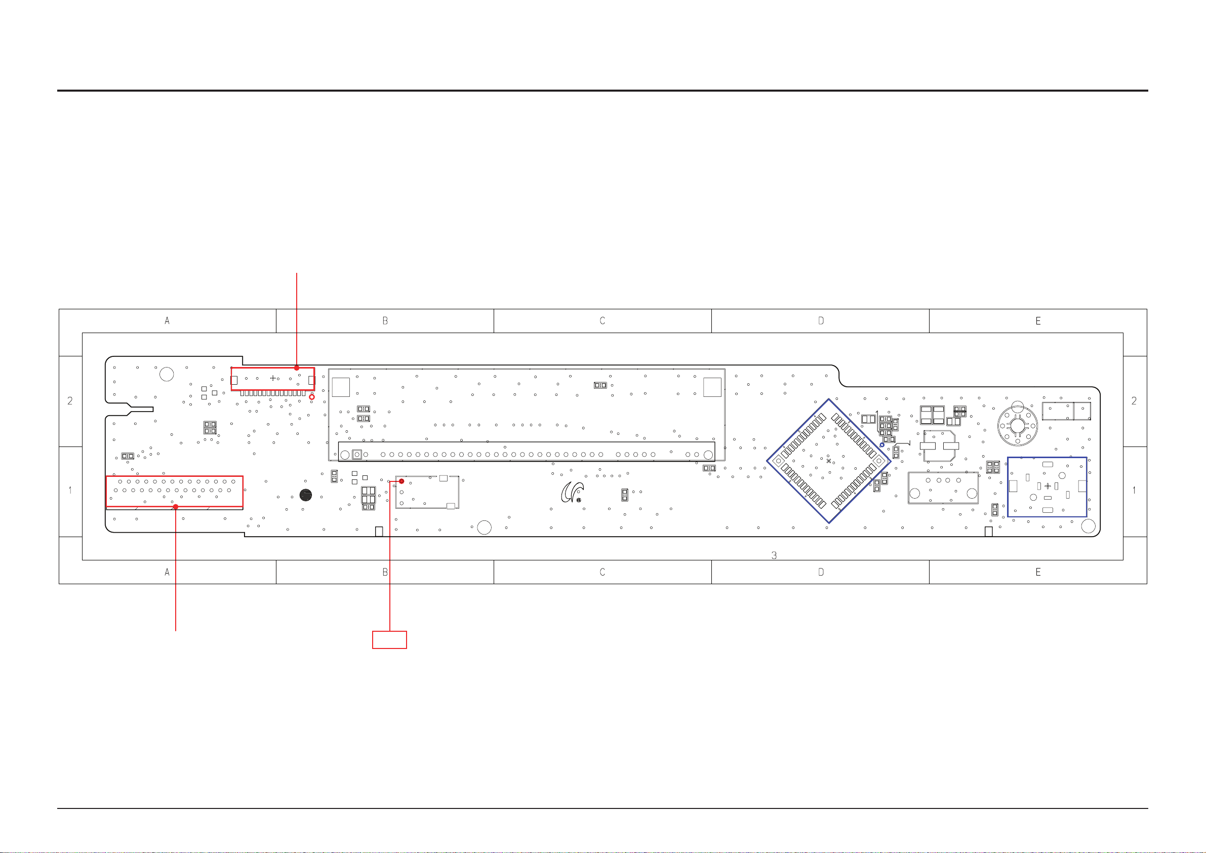
PCB Diagram
MM R 2 1
ES D 1
US B 1
US C 1
RE Y E
US C 2
US C 5
VF R 1
VF R 2
VF R 3
VF R 4
VF R 5
FC 1
FC 2
US D 1
RD 1
RC D 1
FC N 1
MI C 3
AB C 1
L1
L2
AB D 1
FR 7
VF C 1
VF C 2
VF C 4
VF C 6
VF C 7
IC 1
R1
R2
EC C 1
EC C 2
EC C 3
EC C 4
AB L 1
UI C 2
FC O N 1
X- R F
R E V
1
15
15 .S T _L E D
14 .D _ GN D
12 .D _ GN D
13 . T C _ P _K E Y
11 .S T 5. 4 V
10 .D S5 V
1. A S C
2. G N D
3. M I C _ S EN
4. V F D _ C LK
5. V F D _ D AT A
6. V F D _ C E
7. V F D _ G ND
8. V F D _ 4 .6 +
11 . G N D
12 . S T 5 . 4V
13 . M I C _ DA T A
14 . S T _ L ED
16 . D S 5 V
17 . V O L _ LE D
18 . R E M O _I N
19 . V O L _ DO W N
20 . T O U C H_ P _ KE Y
21 . D _ G N D
22 . K E Y _ SD A
23 . K E Y _ SC L
24 . T C _ I NT
25 . G N D
26 . U S B _ DA T A +
27 . U S B _ DA T A -
28 . U S B 5 V
AH41-01305A
HT-C5500_FRONT
2009.12.01
9. D_ G ND
7. SC L
5. DS 5 V
3. VO L _L E D
2. VO L _U P
1. VO L _D O WN
4. D_ G ND
6. SD A
8. NC
9. V F D _ 4 .6 -
10 . V F D _ 28 V
15 . V O L _ UP
00
FCON1
UIC2
MIC3
FCN1
6-2 FRONT PCB Top
1
2
TP1
6-2 Samsung Electronics
Page 77
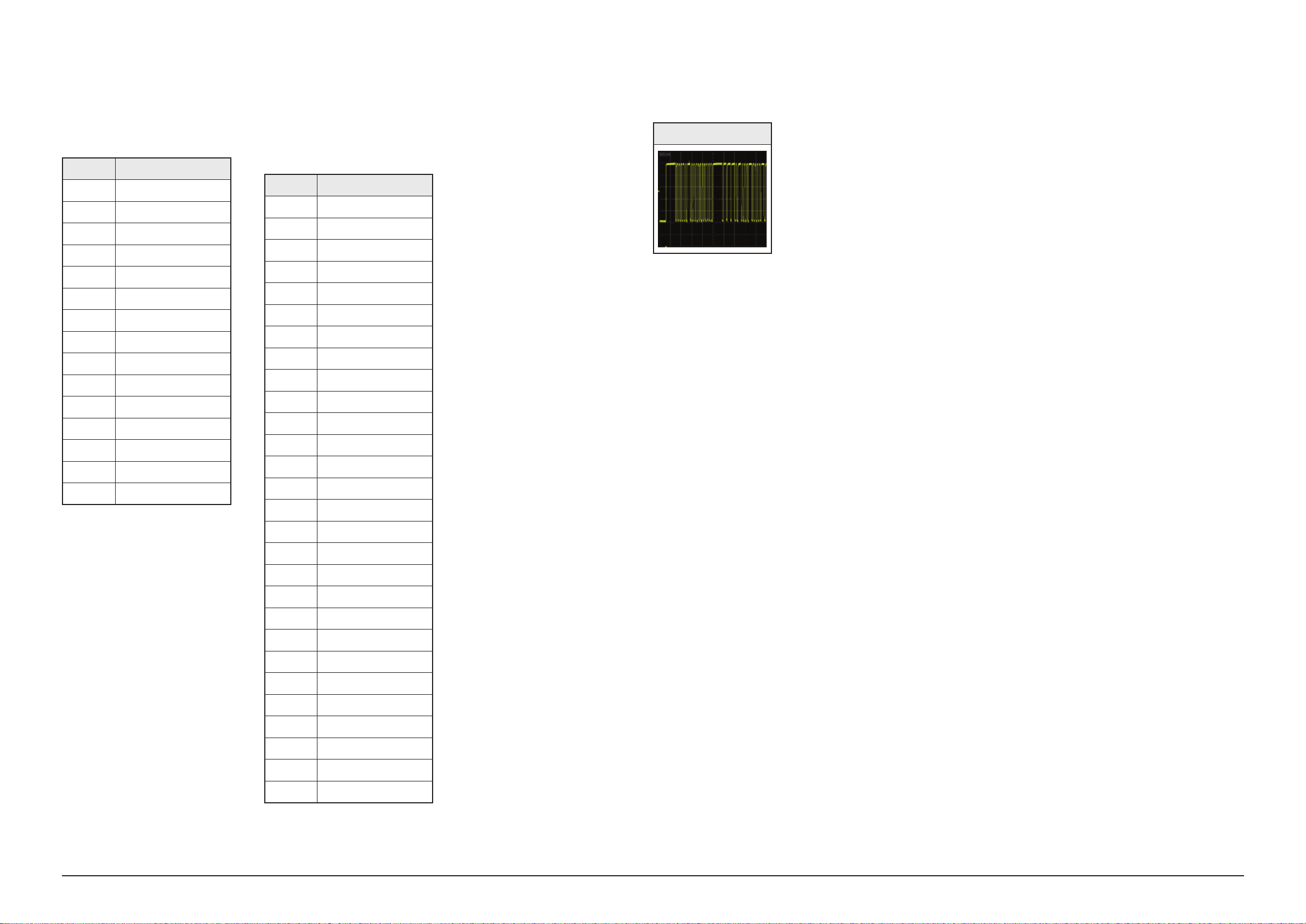
6-2-1 Pin Connection 6-2-2 Test Point Wave Form
PCB Diagram
1 FCN1
Touch Key Interface Connector
Pin No. Signal
1 VOL DOWN
2 VOL UP
3 VOL LED
4 GND
5 5V
6 KEY SDA
7 KEY SCL
8 LED1
9 GND
10 5V
11 5V
12 GND
13 KEY
14 GND
15 PWR ON
2 FCON1
Touch Key / VFD / USB Interface
Connector
Pin No. Signal
1 USP5V
2 DATA-
3 DATA+
4 GND
5 TOUINT
6 TOUCLK
7 TOUDATA
8 GND
9 PWR TOUCH
10 VOL DOWN
11 REMO
12 VOL LED
13 D5V
14 VOL UP
15 RED ONOFF
TP1
16 MIC DATA
17 ST5V
18 GND
19 VFD-28V
20 VFD-
21 VFD+
22 GND
23 VFDCE
24 VFDDATA
25 VFDCLK
26 ASC SEN
27 GND
28 ASC
Samsung Electronics 6-3
Page 78
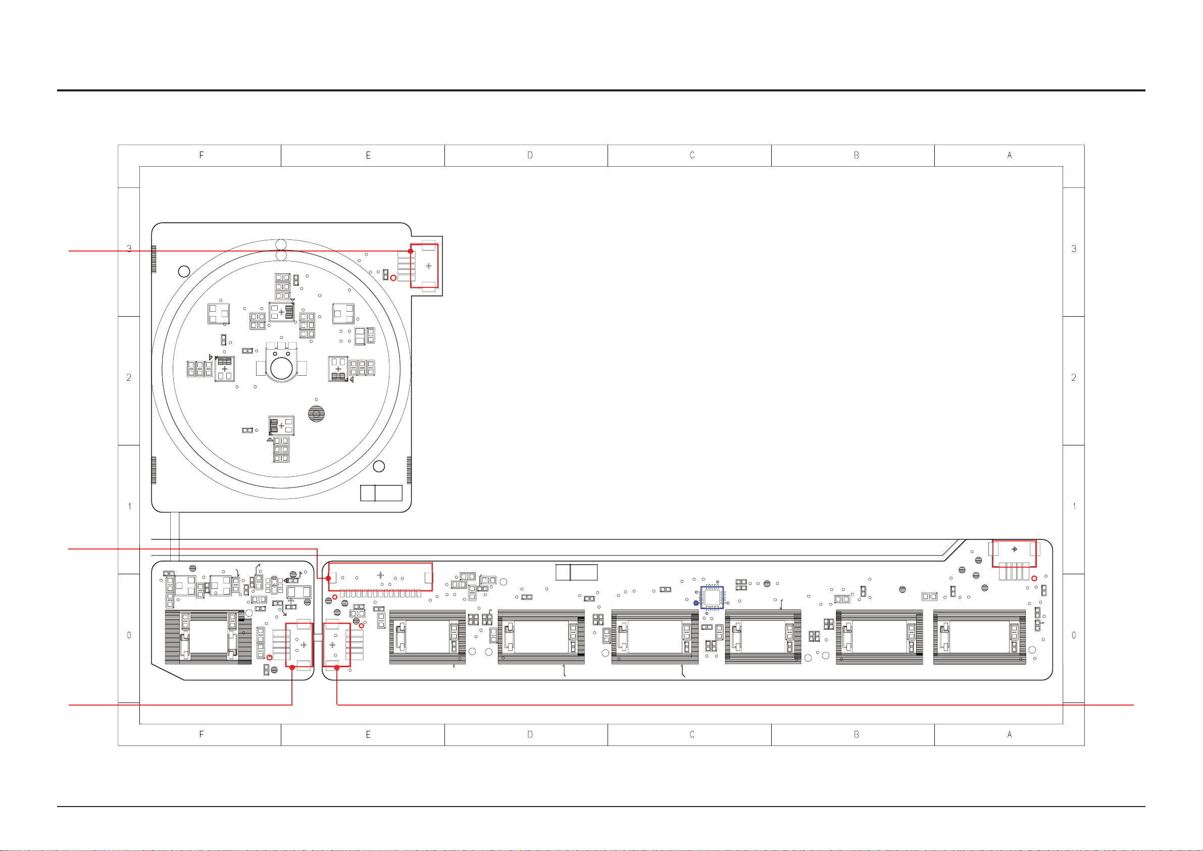
PCB Diagram
15
1
15
1
5
1
5
1
5
VO R1 0
RE S ET
KE Y IC 2
VC ON 2
KE Y R1 0
KE Y R1 1
KE Y R1 3
KE Y R1 4
TO C N1
KE YR 16
KE Y R1 7
KE Y R1 8
KE YR 21
KE YR 22
FU N CT IO N
KE YR 23
KE YR 24
KE YR 25
KE Y R2 7
SW Q 1
KE Y R3 2
SW Q 2
43RYEK33RYEK
KE Y R3 5
KE Y R3 6
KE Y R3 9
VO C1
VO C2
VO C3
VO C4
VO C5
KY C 1
VO C6
KY C 2
VO C7
VO D1
C1
PC N1
RE W
KC 1 3
FF
VL ED 1
VL ED 2
VL ED 3
VL ED 4
VC N1
KE Y C1
KE Y D0
VO L1
KE Y D1
KE Y D2
KE Y D3
7D
Y
EK
4
DY
EK
KE Y D8
L1
PL A Y
L2
L3
L4
L5
IC 1
ST O P
KP D 1
KP D2
KP D 3
KP D4
KP D5
KP D6
KP D 7
KP D 8
VO Q1
VO Q2
PC O N2
UZ D 3
VO R1
VO R2
VO R3
VO R4
VO R5
VO R6
VO R7
VO R8
VO R9
EJ E CT
PO W ER
KE Y R0
KE Y D1 0
KE Y R1
KE Y D1 1
KE Y R2
KE Y D1 2
KE Y D1 3
KE Y R3
KE Y R4
KE Y D1 6
KE Y D1 7
KE Y R7
KE Y R9
KE Y D2 0
KE Y D2 1
OP E N/ CL OS E
F
FY
ALP
P
OTS
FU N CT IO N
RE W
KE YR 15
SW R1
SW R2
KE YD 9
SW C1
SW C2
EM C1
EM C2
EM C6
EM C7
EM C8
EM C9
EM C1 2
EM C1 3
EM C1 4
EM C1 1
EM C1 0
XR F
EM C4
EM C5
EM C3
2 00 9. 10 .0 9
HT - C5 50 0 TO UC H KE Y PC B
RE V
00
00
RE V
RE V :0 0
2 00 9. 10 .0 9
HT - C5 50 0 TO UC H KE Y PC B VO L
HT - C5 50 0
TO U CH K EY P CB P OW ER
AH 41 -0 130 3A
AH 41 -0 130 3A
AH 41 -0 130 3A
KE Y R2 6
AH 41 -0 130 3A
C2
KE YC 4
VCON2
PCON2
PCN1
TOCN1
IC1
VCN1
6-3 KEY PCB Top
1
2
3
6-4 Samsung Electronics
4
Page 79
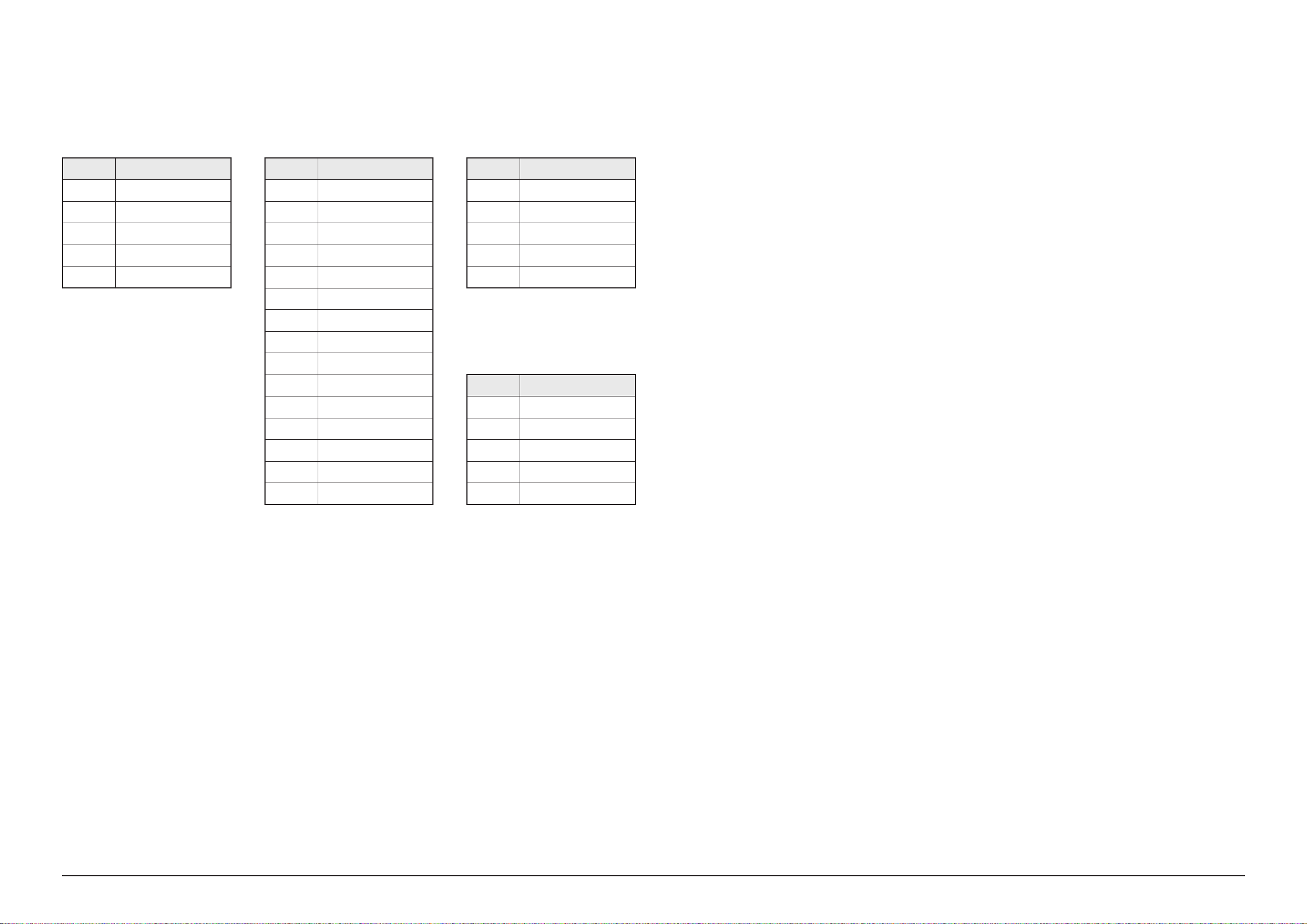
6-3-1 Pin Connection
PCB Diagram
1 VCON2
Volume Interface Connector
Pin No. Signal
1 VOL DOWN
2 VOL UP
3 VOL LED
4 GND
5 5V
2 TOCN1
Volume Interface Connector
Pin No. Signal
1 VOL DOWN
2 VOL UP
3 VOL LED
4 GND
5 5V
6 KEY SDA
7 KEY SCL
8 LED1
9 GND
10 5V
11 5V
12 GND
3 PCON2
Power Key Interface Connector
Pin No. Signal
1 PWR ON
2 GND
3 KEY
4 GND
5 5V
4 PCN1
Power Key Interface Connector
Pin No. Signal
1 5V
2 GND
13 KEY
14 GND
15 PWR ON
3 KEY
4 GND
5 PWR ON
Samsung Electronics 6-5
Page 80

PCB Diagram
CON1
IC5
IC12
IC9
IC8
IC2
NCIC3
IC13
IC14
CON2
CON4
6-4 AMP PCB Top
1
2
6-6 Samsung Electronics
Page 81

6-4-1 Pin Connection
PCB Diagram
1 CON4
AMP Power Connector
Pin No. Signal
1 VARIABLE PWR C
2 PVDD -30V
3 PVDD -30V
4 PVDD -30V
5 SGND
6 SGND
7 SGND
8 PVDD +30V
9 PVDD +30V
10 PVDD +30V
2 CON1
Audio Data / PWM IC Interface
Connector
Pin No. Signal
1 MIC PDN
2 FAN PWR
3 FAN SEN
4 AUOUT3
5 AUOUT2
6 AUOUT1
7 AUOUT0
8 LRCKOUT
9 BCLKOUT
10 GND
11 SO PWM
12 SCK PWM
13 CS PWM
14 SI PWM
15 RESET PWM
16 EXT MUTE
17 RESET POWER
18 SD POWER
19 VARI A
20 VARI B
21 GND
22 AMP3.3V
23 GND
24 AMP -12V
25 GND
26 GND
27 AMP -12V
28 GND
Samsung Electronics 6-7
Page 82

PCB Diagram
CON2
CON4
CON1
IC4
IC7
NCIC1
IC10
IC11
6-5 AMP PCB Bottom
6-8 Samsung Electronics
Page 83

6-6 MAIN PCB Top
IC50
IC402
IC1402
IC1303
IC1701
CEIC1
CN41
CN1302
CN1501
CN5
CF401
CN1601
CN1301
CN6
CN13
CN17
CN12
CN14
IC1601
IC25
IC1703
IC1302
IC1501
IC7
IC1702
IC301
IC1
IC5
IC6
IC17
IC1403
TP2
TP3
TP6
TP5
PCB Diagram
TP4
1
5
4
3
2
Samsung Electronics 6-9
Page 84

PCB Diagram
6-6-1 Pin Connection
1 CN12
DECK PICUP Connector
Pin No. Signal Pin No. Signal
1 SEN_VCC 21 RF+
2 SEN_OUT 22 RF-
3
4 CL 1+ 24 GND
5
6 CL 2- 26 E
7 GND 27 D
8 CD LD 28 C
9 CD VR 29 B
10 MON PD 30 A
11
12 DVD LD 32
13 OPUTYPE 33
14 BD MPD 34
15 GND 35
16 BD PD SLEEP 36
17
18 VREF 1.65V 38
19 VREF 39
20
CL 2+ 23 H
CL 1- 25 F
DVD VR 31
SW DVD/CD STB 37
VCC 5V 40
GND
GND
BD LD
BD HFM
T-
F-
R-
R+
F+
T+
2 CN14
DECK Motor Connector
Pin No. Signal
1 SLD1+
2 SLD1-
3
4 SLD2-
5
6 LDO-
7 CLOSE
8 OPEN
9 GND
10 HV+
11
12 H-
13 HW-
14 HW+
15 HU-
16 HU+
17
18 GND
19 U
20 V
21 W
22
SLD2+
LDO+
SW3
HV-
H+
3 CN1301
Touch Key / VFD / USB Interface
Connector
Pin No. Signal
1 ASC
2 GND
3
4 VFDCLK
5
6 VFDCE
7 GND
8 VFD+
9 VFD-
10 VFD-28V
11
12 ST5V
13 MIC DATA
14 RED ONOFF
15 VOL UP
16 D5V
17
18 REMO
19 VOL DOWN
20 PWR TOUCH
21 GND
22 TOUDATA
ASC SEN
VFDDATA
GND
VOL LED
4 CN1601
MAIN Power Connector
Pin No. Signal
1 SGND
2 SGND
3
4 VFD-
5
6 P_ON
7 SGND
8 SGND
9 D12V
10 D12V
11
12 SGND
13 ST5.4V
14 ST5.4V
15 ST5.4V
16
VFD -32V
VFD+
SGND
SGND
5 CN1302
Audio Data / PWM IC Interface
Connector
Pin No. Signal
1
2
3
4
5
6
7
8
9
10
11
12
13
14
15
16
17
18
19
20
21
22
MIC PDN
FAN PWR
FAN SEN
AUOUT3
AUOUT2
AUOUT1
AUOUT0
LRCKOUT
BCLKOUT
GND
SO PWM
SCK PWM
CS PWM
SI PWM
RESET PWM
EXT MUTE
RESET POWER
SD POWER
VARI A
VARI B
GND
AMP3.3V
23 TOUCLK
24
25 GND
26 DATA+
27 DATA-
28
6-10 Samsung Electronics
TOUINT
USP5V
23
24
25
26
27
28
GND
AMP -12V
GND
GND
AMP 12V
GND
Page 85

6-6-2 Test Point Wave Form
TP2
TP3
PCB Diagram
TP4
TP5
TP6
Samsung Electronics 6-11
Page 86

PCB Diagram
CN6
CN13
IC301
IC1502
IC401
CEIC2
IC405
IC1503
IC16 IC20
IC18
IC1408
IC16
IC11
IC1401
CF401
6-7 MAIN PCB Bottom
TP2
TP5
TP6
TP7
TP4
6-12 Samsung Electronics
Page 87

6-7-1 Test Point Wave Form
TP2
TP4
PCB Diagram
TP5
TP6
TP7
Samsung Electronics 6-13
Page 88

PCB Diagram
D A4
D A5
C A5 N 1
Q M2
C A5 N 2
B D1
L A1
L 12 0 1
M 12 0 1
C X1
C X2
C X3
N TC 1
L F1
C Y
1
C 6
L F2
C Y
2
C Y3
C 7
C Y
4
C 8
C Y5
C Y6
Q 5N 1
C A5 4 0 1C A5 4 0 2
C A5 4 0 4
D R5 N 1
D M3
D M4
D M5
I CF B 5 40 1
W 10 2
W 10 3
W 10 4
W 10 5
W 10 7
W 10 8
W 10 9
I CA F B 1
W 11 0
R PS 1
W 11 1
W 11 3
W 11 4
J 1
W 11 7
W 11 8
L M1
W 11 9
C A1
C A2
C A3
C A4
W 12 0
C A5
W 12 1
C A6
I CA 1
W 12 5
W 12 6
C A1 2 0 1
L N1
W 12 9
C A1 2 0 2
V AR 1
D RA N 1
W 13 0
W 13 1
W 13 3
W 13 5
W 13 6
W 13 7
W 13 8
W 13 9
W 14 0
W 14 1
W 14 3
R M8
W 14 4
M 1
L P1
F 1R
C PS 1
D RA P 1
C A2 2 0
H S1
H S2
D R5 4 0 1
D R5 4 0 2
D R5 4 0 3
R A1 1
O C1
O C2
R A1 3
O C3
R A1 4
O C4
R A1 5
R 1
C AN 1
T 2A
C AN 2
C A3 0 N 01
C A3 0 N 02
Q 30 N 0 1
D R3 0 N 01
T 1
T 2
C AP 1
C AP 2
R M1 0
R M1 1
I C5 N 1
C M3
C M4
I CM 1
D R1 2 0 1
C ON 1
Q 36 0 1
L 54 0 2
C ON 2
C ON 3
C ON 7
C ON 8
C A3 6 0 1
( 11 0V )
( 22 0V )
W 11 6
W 11 5
W 10 6
W 12 4
W 14 2
2 50 V 8A L
P R IM AR Y
C 5 50 0
R EV . PV
2 20 V OP E N
M AN U A L O P EN
1 10 V SH O R T
S E CO ND AR Y
REPLACE FUSE AS MARKED
!
15 . - 1 2( B D) -5 (D V D)
14 . 5 . 4V
13 . 5 . 4V
12 . 5 . 4V
11 . G N D
10 . G N D
9. +1 2 V
8. +1 2 V
7. GN D
6. GN D
5. p- o n
4. +V F D
3. -V F D
2. -V P
1. GN D
GN D
+3 0
+3 0
+3 0
Re f
GN D
-3 0
-3 0
-3 0
GN D
1
1 0
1 10 V OP E N
1
1 5
S AM SU NG V D GV V
2 0 09 .1 0. 15
CON3
CON2
CON1
ICA1
ICM1
6-8 SMPS PCB Top
1
2
6-14 Samsung Electronics
Page 89

6-8-1 Pin Connection
PCB Diagram
1 CON3
MAIN Power Connector
Pin No. Signal
1 VARIABLE PWR C
2 PVDD -30V
3 PVDD -30V
4 PVDD -30V
5
6 SGND
7 SGND
8 PVDD +30V
9 PVDD +30V
10
SGND
PVDD +30V
2 CON2
AMP Power Connector
Pin No. Signal
1 SGND
2 ST5.4V
3 ST5.4V
4 ST5.4V
5
6 SGND
7 D12V
8 D12V
9 SGND
10 SGND
11 P_ON
12 VFD+
SGND
13
14 VFD -32V
15 SGND
16
VFD-
SGND
Samsung Electronics 6-15
Page 90

PCB Diagram
D A 4
D A 5
Q M 1
C A 5 N 1
Q M 2
C A 5 N 2
Q M 3
B D 1
L A 1
Z D A F B 1
L 1 2 0 1
R A 3
R A 5
R A 6
R A 8
R A 9
M 1 2 0 1
Z D 3 0 N 0 1
Z D 1 2 0 1
C X 1
C X 2
C X 3
N T C 1
C 1
C 2
C 4
C 5
C F B 5 4 0 1
L F 1
C Y
1
C 6
C F B 5 4 0 2
L F 2
C Y
2
C Y 3
C 7
C Y 4
C 8
C Y 5
C 5 4 0 1
C Y 6
C 5 4 0 3
Q 5 N 1
Q 5 N 2
C A 5 4 0 1
C A 5 4 0 2
C A 5 4 0 4
D R 3 6 0 1
C A F B 1
C A F B 2
Z D 2
C A F B 3
Q A F B 1
D R 5 N 1
D M 1
D M 2
D M 3
D M 4
D M 5
I C F B 5 4 0 1
W 1 0 2
W 1 0 3
W 1 0 4
R A F B 1
W 1 0 5
R A F B 2
R A F B 3
W 1 0 7
R A F B 4
W 1 0 8
R A F B 5
W 1 0 9
R A F B 6
R A F B 7
I C A F B 1
W 1 1 0
R P S 1
W 1 1 1
R P S 2
R P S 3
W 1 1 3
R P S 4
W 1 1 4
C 1 2 0 1
J 1
C 1 2 0 2
C 1 2 0 3
W 1 1 7
C 1 2 0 4
W 1 1 8
L M 1
R 5 N 1
W 1 1 9
R 5 N 2
C A 1
C A 2
C A 3
C A 4
W 1 2 0
C A 5
W 1 2 1
C A 6
I C A 1
W 1 2 5
W 1 2 6
C A 1 2 0 1
L N 1
W 1 2 9
C A 1 2 0 2
Q R C 0 1
V A R 1
D R A N 1
W 1 3 0
W 1 3 1
W 1 3 3
W 1 3 5
W 1 3 6
W 1 3 7
W 1 3 8
W 1 3 9
R 1 2 0 1
R M 2
R 1 2 0 2
R M 3
R 1 2 0 3
R M 4
W 1 4 0
R M 5
W 1 4 1
R M 6
R M 7
W 1 4 3
R M 8
W 1 4 4
M 1
R M 9
L P 1
F 1 R
C P S 1
D R A P 1
C 5 N 1
C A 2 2 0
H S 1
R A N 1
H S 2
C 3 0 N 0 1
C 3 0 N 0 2
Q A 2
D R 5 4 0 1
D R 5 4 0 2
D R 5 4 0 3
R C 0 1
R A P 1
R A 1 0
R A 1 1
O C 1
R A 1 2
O C 2
R A 1 3
O C 3
R A 1 4
O C 4
R A 1 5
R 1
C A N 1
T 2 A
C A N 2
C A 3 0 N 0 1
C A 3 0 N 0 2
Q 3 0 N 0 1
D P S 1
Q 3 0 N 0 2
D P S 2
D P S 3
D P S 4
D R 3 0 N 0 1
R F B 5 4 0 1
T 1
R F B 5 4 0 2
T 2
R F B 5 4 0 3
R F B 5 4 0 4
R F B 5 4 0 5
C A P 1
C A P 2
R M 1 0
R M 1 1
I C 5 N 1
C M 1
C M 2
C M 3
C M 4
I C M 1
D R 1 2 0 1
C O N 1
Q 3 6 0 1
L 5 4 0 2
C O N 2
C O N 3
C O N 7
C O N 8
R 3 0 N 0 1
R 3 0 N 0 2
C A 3 6 0 1
R 3 6 0 1
R 3 6 0 2
D C 0 1
D A 2
D A 3
W 1 1 6
W 1 1 5
W 1 0 6
W 1 2 4
W 1 4 2
CON3
CON2
CON1
ICM1
ICA1
6-9 SMPS PCB Bottom
6-16 Samsung Electronics
Page 91
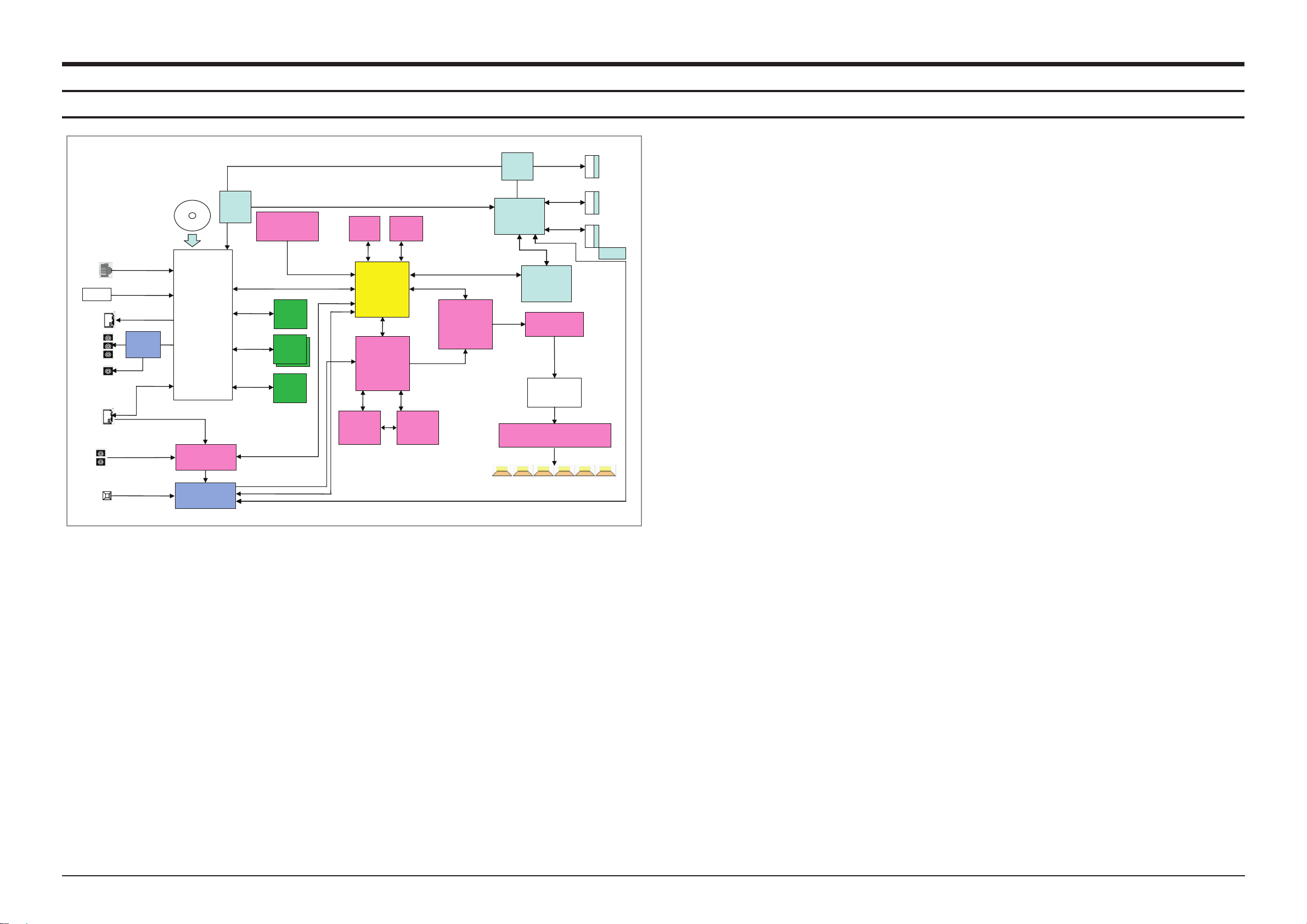
7. Schematic Diagram
BACK END
BCM7630
Video Decoder
Audio Decoder
Optical Disc
Control
HDMI(1.3v)
10bit
(27MHz)
BACK END
BCM7630
Video Decoder
Audio Decoder
Optical Disc
Control
HDMI(1.3v)
10bit
(27MHz)
DSP
TMS320DA788B
DSP
TMS320DA788B
5 wire Serial Communication
Serial Communication
5 wire
Serial Communication
Ethernet
USB X 2
TMDS
CVBS
Analog
Y Pb Pr
Analog
DDR3 1G
X 2 8bit
(667MHz)
NAND
FLASH
1G
Serial
Communication
DDR3 1G
16bit
(667MHz)
DDR Memory
Communication
DDR Memory
Communication
Analog
Audio
Input
I2C Communication
iPod
UART
Communication
4 wire Serial Communication
DIGITAL
TUNER
4702i
DIGITAL
TUNER
4702i
FLASH
1M X 16
AT49BV163
FLASH
1M X 16
AT49BV163
SDRAM
8M X 16
K4S281632
SDRAM
8M X 16
K4S281632
Serial
Communication
Wireless
Rear
Wireless
Rear
I2C
Communication
PWM Modulator
PS9830B
PWM Modulator
MAIN U-com
LC87F5CC8A
IC VIDEO
AMP
MM1797
AUDIO DIR
AK4113
PS9830B
CEC SUBMICOM
MC80C0316
4MHz
CEC SUBMICOM
MC80C0316
4MHz
UART Communication
4 wire Serial Communication
I2S
IRS2053M X 2
AUDIO DRIVER
IRS2053M X 2
AUDIO DRIVER
OPAMP
X 3
OPAMP
X 3
6CH
POWER FETIRF6645
X 12
POWER FETIRF6645
X 12
5.1CH SPEAKER OUTPUT
OPTICAL
SPDIF/IN
I2S
HDMI MICOM
EPF005N
HDMI TX, RX SOC
EP94A2K
HDMI IN 1
HDMI IN 2
I2C
I2C
HDMI TX
TMDS
TMDS
TMDS
RESISTOR
SWITCH
RESISTOR
SWITCH
OPTION
HDMI IN
I2S DATA and CLK
AUDIO FUNCTION IC
AK5367
7-1 Overall Block Diagram
Schematic Diagram
From DISC, RF signal is transmited to BACKEND BCM7630. The decoder BCM7630 decodes the RF signal to VIDEO
and AUDIO DATA.
Analog video signal goes through VIDEO AMP MM1797 and is outputed to COMPONENT(Y,Pb,Pr) and CVBS.
About Digital Video signal, HDMI goes through HDMI TX jack. In case of supporting HDMI IN, HDMI SOC EP94A2K
gets TMDS DATA from BCM7630 and HDMI IN JACK and after packing the data, it sends the data to TX Jack.
HT-C5500 supports 2 USB ports. One is for USB FILE PLAY like MP3, JPG, DivX and etc. The other is for WiFi
wireless LAN.
i-Pod, i-Phone are also supported. About BCM7630 Audio OUTPUT, I2S data goes through DSP TMS320DA788 and
then DSP IC decodes or bypass the data to PWM IC. External AUDIO INPUT also goes throuch DSP TMS320DA788
and then goes through like BCM7630 AUDIO pass. From PWM modulator PS9630B to LPF(Low Pass Filter), DIGTAL
SIGNAL is changed to Analog Signal and amplified by OP-AMP and FET IR AMP.
Samsung Electronics 7-1
This Document can not be used without Samsung’s authorization.
Page 92

Schematic Diagram
P[6]
P[5]
P[5]
P[3]
P[4]
P[4]
P[3]
P[2]
P[2]
P[1]
P[1]
P[22]
G[9]
G[8]
G[7]
G[6]
G[5]
P[22]
G[4]
P[21]
G[3]
P[20]
G[2]
P[21]
G[1]
P[20]
G[2]
P[18]
P[19]
G[3]
P[19]
P[17]
G[9]
G[4]
P[17]
P[18]
G[8]
G[5]
P[15]
P[16]
G[7]
G[6]
P[15]
P[16]
G[1]
P[14]
P[13]
P[13]
P[14]
P[11]
P[11]
P[12]
P[9]
P[10]
P[12]
P[8]
P[10]
P[9]
P[7]
P[7]
P[8]
P[6]
ST5. 4V
D_GN D
ST5V
FC1
47n F
RCD1
200m A
FR7
47
FC2
1000 0nF
REMO_I N
FCN1
15P, ANG
1
2
3
4
5
6
7
8
9
10
11
12
13
14
15
VOL_DO WN
VOL_UP
ST_LED _OFF
D_GND
ST5. 4V
RD1
200m A
KEY_SC L
KEY_SD A
VOL_LE D
TOUCH_ POWER_K EY
VFR3
100
VFR1
10K
VFD_ GND
VFD_ GND
VFD_-2 8V
IC1
HNV- 09SS 82T
1
F+_12F+_231G4P15P26P37P482G9P510P611P7123G13P814P9154G16P10175G18P1119P1220P1321P14226G23P1524P16257G26P1727P18288G29P19309G31P2032P2133P22
34
F-_135F-_2
VFD_ GND
VFR5
82K
VFC1
1000 0nF
VFD-
VFD+
VFC6
100n F
VFD_ GND
VFD_ GND
VFC7
100n F
DS5V
ESD1
MLVS -060 3-E0 8
VFC4
100n F
VFD_CE
VFC2
100n F
VFD_DA TA
VFR4
100
VFD_CL K
UIC2
PT6324-QL
1
CLK2DIN3STB4DOUT5K16K27OSC8GND_ 89VDD_ 910SG1/ KS111SG2/ KS212SG3/ KS313SG4/ KS4
14
SG5/ KS5
15
SG6/ KS6
16
SG7/ KS7
17
SG8/ KS8
18
SG9/ KS9
19
SG10 /KS1 0
20
SG11 /KS1 1
21
SG12 /KS1 2
22
SG13 /KS1 3
23
SG14 /KS1 4
24
SG15 /KS1 5
25
SG16 /KS1 6
26
SG17
27
SG1828SG1929SG2030SG2131SG2232SG2333SG24
34
GR135GR236GR337GR438GR539GR6
40
GR7
41
GR8
42
GR9
43
GR10
44
GR11
45
GR12
46
GR13
47
GR14
48
GR15
49
GR16
50
VEE
51
VDD_ 51
52
GND_ 52
VFR2
100
MIC 3
7P
1
2
3
4
5
6
7
ASC_IN
ABL1
AB
ASC_SE NSE
D_GN D
ABD1
MLVS -060 3-E0 8
ABC1
10nF (OPE N)
D_GN D
D_GN D
USB1
1
1
3
3
4
4
2
2
USC1
100n F
USB5V
USB1_D ATA-
D_GN D
D_GN D
USB1_D ATA+
USC2
47uF
16V
USC5
1000 0nF
USD1
MLVS -060 3-E0 8
VFD_ GND
USB1_D ATA-
REMO_I N
VFD_DA TA
D_GN D
DS5V
KEY_SD A
USB5V
VFD+
ST5. 4V
MMR2 1
10K
ST_LED _OFF
VFD_CL K
KEY_SC L
ASC_SE NSE
DS5V
VFD_-2 8V
FCON 1
28P, ANGL E
1
2
3
4
5
6
7
8
9
10
11
12
13
14
15
16
17
18
19
20
21
22
23
24
25
26
27
28
ASC_IN
VFD_CE
VFD-
USB1_D ATA+
D_GN D
TOUCH_ POWER_K EY
VOL_DO WN
VOL_LE D
VOL_UP
R1
33
R2
33
DS5V
ECC1
100n F
ECC2
100n F
ECC3
100n F
D_GN D
ECC4
100n F
D_GN D
L1
OPEN
L2
1uH
DS5V
REYE
HORI ZONT AL
1
OUT
3
GND
2
VCC
REMOCON-EYE PARTS
DGND
DGND
+5V
KEY
DGND
KEY_SD A
LED1
DGND
+5V
VOULUM E_UP
+5V
KEY_SC L
VOLUME _LED
VOLUME _DOWN
PWR_ON
VFD_PARTS
ASC_PARTS
USB_PARTS
-28V
PWR_ TOUCH_ KEY
GND
VFD4 .6V(+)
ASC_ MIC_SE NSE
VOL_L ED
GND
ASC
VOL_ DOWN
+5V
REMO TE CON
CLK_ VFD
G ND
GND
DATA -
GND
VOL_ UP
DATA _VFD
TC_ CLK
T C_DATA
DAT A+
VFD4 .6(-)
STAN DBY IN D
USB5 V
CE_V FD
+5.6 V
MIC_ DATA
TC_I NT
C6500_ TOUCH_R ST2
C6500_ MIC
C6500_ KEY_UPD ATE
C6500_ RST1
C6500_ MIC_CLK
C6500_ TOUCH_I NT
C6500_ MIC_DAT A
7-2 FRONT
POWER
AUDIO
TP1
TP1
7-2 Samsung Electronics
This Document can not be used without Samsung’s authorization.
Page 93
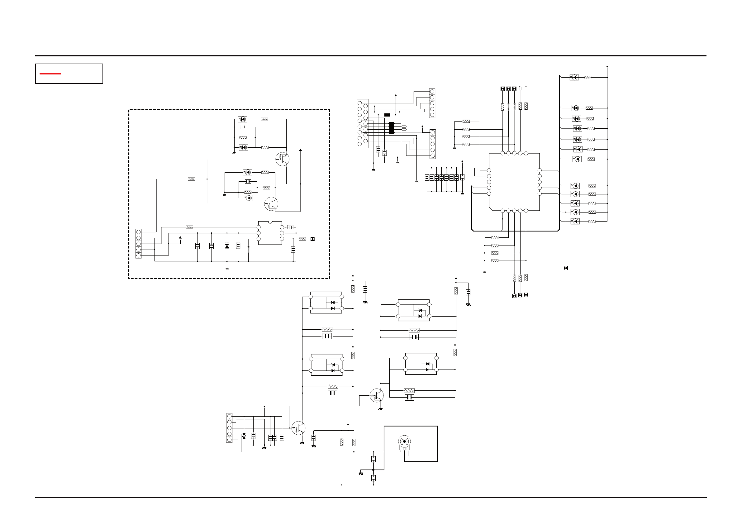
7-3 KEY
POWER ON_LED
POWER _TOUCH_ 1KEY
LED[1 ]
LED[4 ]
LED[4 ]
LED[0 ]
LED[3 ]
LED[7 ]
LED[2 ]
LED[3 ]
LED[7 ]
LED[3 ]
LED[4 ]
LED[2 ]
LED[0 ]
LED[2 ]
LED[1 ]
LED[7 ]
LED[0 ]
LED[1 ]
POW ER
PGND
UZD 3
RLZ 5.1B
KEY D21
LED (OPE N)
SWQ 1
KSR 2103
KEY D20
?
PGN D
SWQ 2
KSR 1103
5V
PGN D
5V
KEY R11
0
KEY R13
0
KC1 3
100 nF
KEY R27
820
KEY R26
820 (OPE N)
PCO N2
5P, SMD- A
1
2
3
4
5
KEY R18
220
KEY R17
220
KEY_S CL
GND
KEY D8
?
REW
KEY R39
1K
KEY D16
?
KEY R32
1K
L3
AB
L5
AB
KEY R33
1K
GND
L1
AB
L2
AB
KEY R34
1K
KEY D17
?
STO P
EJE CT
KEY R35
1K
KEY R36
1K
KYC 1
100 nF
P5V
KEY_S DA
GND
PCN 1
5P, SMD- A
1
2
3
4
5
KYC 2
100 nF
KEY_S CL
KEY R24
1K
KEY D11
?
+5V
+5V
FF
KEY_S DA
KEY R25
1K
KEY D12
?
IC1
TC1 0QF2 0IF
1
RESE TB/A DCH0 /P1 .22TS7/ T0/A DCH2 /P2 .03TS6/ T1/A DCH3 /P2 .14TS5/ ADC1 1/P2 .25TS4/ ADC1 0/P2 .3
6
ADC9 /P2. 4
7
ADC8 /P2. 5
8
CLO/ ADC7 /P2. 6
9
ADC6 /P0. 7
10
ADC6 /P0. 6
11
P0.5 /ADC 4/SC L012P0.4 /ADC 3/SD A0
13
P0.3 /ADC 2/IN T3/ TS3
14
P0.2 /ADC 1/IN T2/ TXD/ TS2/ SDA115P0.1 /ADC 0/IN T1/ RXD/ TS1/ SCL1
16
P0.0 /ADC H7/I NT0 /TVO /(PW M)/T S0
17
VDD
18
VSS
19
P1.0 /XTA L1
20
P1.1 /XTA L2
TOC N1
15P ,ANG
1
2
3
4
5
6
7
8
9
10
11
12
13
14
15
KEY R16
1K
KEY D13
?
KEY R23
1K
FUN CTIO N
+5V
PLA Y
GND
KEY R22
1K
KEY R21
1K
GND
VCN 1
5P, SMD- A
1
2
3
4
5
RES ET
KEY C1
100 nF
L4
AB
P_GND
KEY D7
whi te
KEY D1
KEY D2
KEY D4
KEY D0
KEY D3
KEY R1
330
KEY R4
330
KEY R3
330
KEY R2
330
KEY R0
330
KEY R7
330
KEY D9
red
SWC 2
47n F
SWR 2
10K
KEY R14
150
SWR 1
10K
SWC 1
47n F
KEY D10
whi te
EMC 2
100 nF
EMC 1
100 nF
EMC 9
100 nF
EMC 8
100 nF
EMC 7
100 nF
EMC 6
100 nF
EMC 5
100 nF
EMC 4
100 nF
EMC 3
100 nF
KEY IC2
SS5 01
1 OU TPUT
2 VD D
3 BI AS
4
SEN S
5
GND
6
Cr
KEY R10
10K
KEY C4
0.0 02nF (OPEN )
KEY R9
2.2 K
C2
0.0 05nF
KPD 6
150 K
KPD 7
150 K
KPD 8
150 K
KPD 5
150 K
KPD 1
150 K
KPD 4
150 K
KPD 2
150 K
KPD 3
150 K
VOR 8
560
VOC 1
47n F
VLE D1
67- 31AZ SUBP- S204 6-TR 8
1
-1
2
+
3
-2
4
-3
VGN D
VOR 4
10K
V5V
VOD 1
MLV S-06 03-E0 8
VLE D3
67- 31AZ SUBP- S204 6-TR 8
1
-1
2
+
3
-2
4
-3
VGN D
VO R1
10 K
VOR 9
560
V5V
VOR 7
560
VGN D
EMC 14
100 nF
VGN D
VO C3
10 nF
VLE D4
67- 31AZ SUBP- S204 6-TR 8
1
-1
2
+
3
-2
4
-3
EMC 13
100 nF
VO C7 1 0nF
VO R3
10 K
VO R5
10 K
V5V
VO C6
10 nF
VOC 4
47n F
EMC 12
100 nF
VOQ 1
KSR 1103
VOL 1
EC0 5E12 2040 1
1
A
B
2
C
3
V5V
V5V
VGN D
VOR 2
10K
VO C2
10 nF
EMC 11
100 nF
VOQ 2
KSR 1103
VOC 5
47n F
VO R6
10 K
VGN D
V5V
VLE D2
67- 31AZ SUBP- S204 6-TR 8
1
-1
2
+
3
-2
4
-3
VCO N2
5P, SMD- A
1
2
3
4
5
VOR 10
560
C1
100 00nF
EMC 10
100 nF
VGN D
KEY R15
680
1/1 0W
HT-BD3250 Touch Key
POW ER KEY
POW ER
RED
WHI TE
PWR_O N
DGND
KEY
DGND
+5V
PWR_O N
+5V
DGND
STOP
FF
PWR_O N
+5V
VOULU ME_UP
REW
KEY_S DA
DGND
DGND
FF
WHITE
TOUCH_KEY_PARTS
REW
VOULU ME_UP
LED1
DS5V
PLAY
OPE/C LOSE
FF
LED6 VOL_UP
KEY
VOLUM E_DOWN
+5V
FUNCT ION
KEY_S CL
PLAY
VOLUM E_DOWN
OPE/C LOSE
DGND
YEONH O 10019 HR-15A0 0
VGND
PGND
PLAY
VOLUM E_LED
FUNCT ION
LED5 VOL_DOW N
+5V
VOLUM E_LED
PGND
STOP
OPE/C LOSE
KEY
if us ing SS5 02, KEY ER10 is 470K , KEYC4 i s O ohm
C2 mu st be N .C
DS5V
VOLUM E_DOWN
VOLUME PARTS
VOULU ME_UP
VGND
VOLUM E_LED
Schematic Diagram
POWER
This Document can not be used without Samsung’s authorization.
Samsung Electronics 7-3
Page 94

Schematic Diagram
I2C
PWM_RR+
PWM_RR-
C52
50V
R51
1/10W47OHM
1/10W
R50
47OHM
R52
1/10W47OHM
R53
47OHM 1/10W
PWM_SW+
R54
47OHM 1/10W
PWM_SW-
R55
1/10W47OHM
PWM_C+
R56
47OHM
1/10W
PWM_C-
R57
47OHM 1/10W
PWM_RL+
R58
47OHM
1/10W
PWM_RL-
R59
47OHM
1/10W
PWM_FR+
PWM_FR-
PWM_FL-
PWM_FL+
AD_BCLK
MICIN
AD_LRCK
AD_MCLK
10KOHM
10KOHM
10KOHM
1/10W
47OHM
47OHM
47OHM
47OHM
47OHM
R26
1/10W
R27
1/10W
1/10WR25
R24 1/10W
R23
1/10W
47OHMR22 1/10W
R21
10KOHM
AUDATA(3)
AUDATA(2)
10KOHM
10KOHM
AUDATA(1)
AUDATA(0)
LRCK(OUT)
BCK(OUT)
/RESET(POWER)
EXT_MUTE(PWM)
MOSI(PWM)
D3.3V
0.01OHM
NCL9
5000MA
K_+3.3V
K_+5V
5000MA
NCL8
0.01OHM
VAA+5V
K_+5V
K_+3.3V
+12V_FAN
5000MA
0.01OHM
L1
+12V_FAN+12VA
D3.3V
0.01OHM
5000MA
L4
D3.3V
D3.3V
+12VA
-12VA
D3.3V
C18
100NF
50V
BCK
9
8
7
6
5
4
3
28
27
26
25
24
23
22
21
20
2
19
18
17
16
15
14
13
12
11
10
1
CON1
10022HS-28C00
S_GND
FGND
R1
47KOHM
1/10W
2
1
CON2
5267-02A
F2 F1
C243
16V
10UF
C244
16V
10UF
C245
16V
10UF
C246
16V
10UF
FGND
L2
5000MA
0.01OHM
R2
1/4W
18OHM
FGND
C2
16V
10UF
Q2
2SC1623-L
R8
4.7KOHM
1/10W
R10
10KOHM
1/10W
FGND
Q4
DTC124EK
C1
16V
10UF
R7
39OHM
1W
Q1
2SA1979S-Y
R6
56OHM
1/2W
R9
47KOHM
1/10W
R11
3.3KOHM
1/10W
Q3
2SA1979S-Y
DGND
A_GND
C247
16V
10UF
C24810UF
16V
C249
10UF
16V
C250
16V
10UF
R12
100KOHM
1/10W
R49
1/10W
10KOHM
D1
75V
1N4148WS
R14
47KOHM
1/10W
R15
SPK_FL
1/10W
47KOHM
C4
2.2UF
50V
FGND
R13
10KOHM
1/10W
C3
25V
10UF
C5
100NF
50V
+12V_FAN
NCC21
10UF
16V
DGND
2
1
NCCON3
5267-02A
K1K2
NCR33
1/16W
3.9KOHM
NCR32
3.9KOHM
1/16W
NCC26
2.2UF
10V
NCC27
2.2UF
10V
R16
1/10W
LRCK AUDATA
DGND
L3
5000MA
0.01OHM
R17
1/10W
R18
1/10W
R19
1/10W
R20
1/10W
C8
100NF
50V
C10
100NF
50V
C13 100NF
50V
C15
100NF
50V
C22
100NF
50V
C21
100NF
50V
R31
0OHM
1/10W
R28
1/10W
0OHM
L5
0.01OHM
5000MA
C24
100NF
50V
C23
100NF
50V
M1M3M5 M8
M7
M9
M10
M11M13
M12
M15
M14
M17
M16M18
M20
M21
M22
M23
M24M26
M25M27
M28
C9
10UF
16V
C12
100NF
50V
C6
10V
10UF
C7
10UF
10V
C19
100NF
50V
C17
100NF
50V
C16
16V
10UF
C11
10V
10UF
C14
10UF
10V
C20
10UF
10V
MGND1
3
2
1
NCIC1
NCC29
10UF
16V
NCC22
10UF
16V
KAGND
NCC36
10UF
16V
NCC23
2.2UF
50V
A_GND
98
7
6
5
4
3
2
16
15
14
13
12
11
10
1
NCIC3
NCR35
4.7KOHM
1/16W
NCR81
4.7OHM
1/10W
NCL7
0.01OHM
5000MA
KAGND
NCR42
100OHM 1/16W
NCR43
100OHM
1/16W
NCR38
1/16W
4.7KOHM
NCR41
100OHM 1/16W
NCR40 100OHM
1/16W
NCR39
4.7KOHM
1/16W
PWM_HP_R-
PWM_HP_L-
C31
100NF
50V
9998979694939291909898887868584838281
808797877
76
75
74
73
72
71
70
7 69
68
67
66
65
64
63
62
61
60
6
59
58
57
56
55
54
53
52
51
50
5
49
48
47
46
45
44
43
42
41
40
4
39
38
37
36
35
34
33
32
31
30
3
29
28
27
26
25
24
23
22
21
20
2
19
18
17
16
15
14
13
12
11
100
10
1
IC2
PS9830B
95
C37
100NF
50V
C40
100NF
50V
PWM_HP_R+
C43
100NF
50V
PWM_HP_L+
C45
100NF
50V
C47
100NF
50V
C48
100NF
50V
100NF
50V
C51
100NF
C50
100NF
50V
C49
100NF
50V
KAGND
NCR5
2.7KOHM
1/10W
NCR4
1.2KOHM
1/16W
R61
1/10W
47OHM
R60 1/10W
47OHM
PWM_FR-
PWM_FR+
PWM_FL+
PWM_FL-
C28
100NF
50V
C30
100NF
50V
DGND
C32
100NF
50V
C34
100NF
50V
C39
100NF
50V
R37
1MOHM
1/10W
R36
120OHM
1/10W
C38
24PF
50V
X1
12.288MHZ
NCR34
22KOHM
1/10W
R77
1/10W
470OHM
DGND
C42
100NF
50V
C44
100NF
50V
R44
100OHM 1/10W
C41
24PF
50V
R45
100OHM 1/10W
R47
100OHM 1/10W
R46
100OHM 1/10W
C46
100NF
50V
DGND
NCR3
4.7KOHM
1/16W
R4
1/16W
4.7KOHM
BCK(OUT)
LRCK(OUT)
AUDATA(0)
AUDATA(1)
AUDATA(2)
AUDATA(3)
/RESET(PWM)
MIC_PDN
MISO(PWM)
CS(PWM)
MOSI(PWM)
VARIABLE_POWER_CTRL_B
_SD(POWER)
VARIABLE_POWER_CTRL_A
MISO(PWM)
SCK(PWM)
CS(PWM)
FAN_CHK
FAN_POWER
EXT_MUTE(PWM)
FAN_CHK
FAN_POWER
/RESET(PWM)
MICIN
AD_LRCK
AD_MCLK
AD_BCLK
MIC_PDN
SCK(PWM)
IO_VSS
DVSS
PWM5_P
PWM5_M
PWM_HP_R_M
IO_VDD
IO_VSS
PWM_SWL_P
PWM_SWL_M
DVSS
DVDD
MIC_SDIN
MIC_LRCK
MIC_BCK
MIC_MCLK
IO_VDD
IO_VSS
EXT_MUTE
SSDIN3
SSDIN2
DVDD
SCK/SCL
SO/SDA
EPD_ENA
SLRCK
SBCK
MSDIN3
MSDIN2
IO_VDD
PWM7_P
PWM7_M
IO_VSS
MLRCK
MBCK
IO_VDD
IO_VSS
PLL_AVSS
IO_VSS
PLL_AVDD
IO_VSS
IO_VDD
PLL_DVDD
PLL_DVSS
IO_VSS
PWM4_P
PWM4_M
IO_VSS
IO_VDD
PWM3_P
PWM3_M
IO_VSS
PWM2_P
OVERLOAD
PWM8_P
PWM8_M
IO_VSS
IO_VDD
PWM_HP_L_P
PWM_HP_L_M
IO_VSS
PWM6_P
PWM6_M
DVDD
IO_VDD
TEST_MODE2
TEST_MODE1
/RESET
IO_VSS
IO_VDD
DMIX_MCLK
DVSS
DVDD
DMIX_SDOUT
DMIX_BCK
DMIX_LRCK
XOUT
XIN
IO_VSS
SPI/I2C
/CS/I2C_AD2
SI/I2C_AD0
DVSS
PWM_HP_R_P
IO_VSS
SSDIN1
SSDIN0
IO_VDD
IO_VSS
PWM2_M
IO_VSS
PWM1_P
PWM1_M
MSDIN1
MSDIN0
DVSS
DVDD
DVSS
DVDD
TEST_MODE3
SCAN_ENA
DIF
CKS0
DGND
VD
LRCK
SDTO
VA
AGND
MCLK
VCOM
PDN
CKS2
SCLK
CKS1
AINL
AINR
EBC
E
B
C
EBC
E
B
C
GND
GND
OUTIN
I2C
50V
1/10W47OHM
1/10W47OHM
1/10W47OHM
1/10W47OHM
47OHM
1/10W
47OHM
1/10W
47OHM
1/10W
1/10W
1/10W
1/10W
1/10W
1/10W
1/10W
5000MA
0.01OHM
+12V_FAN+12VA
0.01OHM
5000MA
D3.3V
100NF
50V
10022HS-28C00
S_GND
FGND
47KOHM
1/10W
5267-02A
16V
10UF
16V
10UF
16V
10UF
16V
10UF
FGND
5000MA
0.01OHM
1/4W
18OHM
FGND
16V
10UF
2SC1623-L
4.7KOHM
1/10W
10KOHM
1/10W
FGND
DTC124EK
16V
10UF
39OHM
1W
2SA1979S-Y
56OHM
1/2W
47KOHM
1/10W
3.3KOHM
1/10W
2SA1979S-Y
DGND
A_GND
16V
10UF
10UF
16V
10UF
16V
16V
10UF
100KOHM
1/10W
1/10W
10KOHM
75V
1N4148WS
47KOHM
1/10W
1/10W
47KOHM
2.2UF
50V
FGND
10KOHM
1/10W
25V
10UF
100NF
50V
10UF
16V
DGND
5267-02A
1/16W
3.9KOHM
3.9KOHM
1/16W
2.2UF
10V
2.2UF
10V
1/10W
DGND
5000MA
0.01OHM
1/10W
1/10W
1/10W
1/10W
100NF
50V
100NF
50V
100NF
50V
100NF
50V
100NF
50V
100NF
50V
0OHM
1/10W
1/10W
0OHM
0.01OHM
5000MA
100NF
50V
100NF
50V
10UF 16V
100NF
50V
10V
10UF
10UF
10V
100NF
50V
100NF
50V
16V
10UF
10V
10UF
10UF
10V
10UF 10V
10UF
16V
10UF
16V
KAGND
10UF
16V
2.2UF
50V
A_GND
4.7KOHM
1/16W
4.7OHM
1/10W
0.01OHM
5000MA
KAGND
100OHM
1/16W
1/16W
4.7KOHM
100OHM
1/16W
4.7KOHM
1/16W
100NF
50V
PS9830B
100NF
50V
100NF
50V
100NF
50V
100NF
50V
100NF
50V
100NF
50V
100NF
50V
100NF
100NF
50V
100NF
50V
KAGND
2.7KOHM
1/10W
1.2KOHM
1/16W
1/10W
47OHM
1/10W
47OHM
100NF
50V
100NF
50V
DGND
100NF
50V
100NF
50V
100NF
50V
1MOHM
1/10W
120OHM
1/10W
24PF
50V
12.288MHZ
22KOHM
1/10W
1/10W
470OHM
DGND
100NF
50V
100NF
50V
24PF
50V
100NF
50V
DGND
4.7KOHM
1/16W
1/16W
4.7KOHM
C52
R51
R50
R52
R53
R54
R55
R56
R57
R58
R59
R21
L1
L4
C18
BCK
CON1
R1
CON2
F2 F1
C243
C244
C245
C246
L2
R2
C2
Q2
R8
R10
Q4
C1
R7
Q1
R6
R9
R11
Q3
C247
C248
C249
C250
R12
R49
D1
R14
R15
C4
R13
C3
C5
NCC21
NCCON3
2K 1K
NCR33
NCR32
NCC26
NCC27
R16
L3
R17
R18
R19
R20
C8
C10
C13
C15
C22
C21
R31
R28
L5
C24
C23
M1
M3 M7
M9
M10M12
M15
M14
M17M20
M21
M22
M23
M28
C9
C12
C6
C7
C19
C17
C16
C11
C14
C20
NCIC1
NCC29
NCC22
NCC36
NCC23
NCIC3
NCR35
NCR81
NCL7
NCR42
NCR43
NCR38
NCR41
NCR40
NCR39
PWM_HP_R-
PWM_HP_L-
C31
IC2
C37
C40
PWM_HP_R+
C43
PWM_HP_L+
C45
C47
C48
C51
C50
C49
NCR5
NCR4
R61
R60
PWM_FR-
PWM_FR+
PWM_FL+
PWM_FL-
C28
C30 C32
C34
C39
R37
R36
C38
X1
NCR34
R77
C42
C44
R44
C41
R45
R47
R46
C46
PWM_RR+
PWM_RR-
PWM_SW+
PWM_SW-
PWM_C+
PWM_C-
PWM_RL+
PWM_RL-
PWM_FR+
PWM_FR-
PWM_FL-
PWM_FL+
AD_BCLK
MICIN
AD_LRCK
AD_MCLK
SPK_FL
MISO(PWM)
CS(PWM)
MOSI(PWM)
FAN_CHK
FAN_POWER
/RESET(PWM)
MICIN
AD_LRCK
AD_MCLK
AD_BCLK
MIC_PDN
SCK(PWM)
9
8
7
6
5
4
3
28
27
26
25
24
23
22
21
20
2
19
18
17
16
15
14
13
12
11
10
1
2
1
2
1
MGND1
3
2
1
98
7
6
5
4
3
2
16
15
14
13
12
11
10
1
9998979694939291909898887868584838281
808797877
76
75
74
73
72
71
70
7 69
68
67
66
65
64
63
62
61
60
6
59
58
57
56
55
54
53
52
51
50
5
49
48
47
46
45
44
43
42
41
40
4
39
38
37
36
35
34
33
32
31
30
3
29
28
27
26
25
24
23
22
21
20
2
19
18
17
16
15
14
13
12
11
100
10
1
95
IO_VSS
DVSS
PWM5_P
PWM5_M
PWM_HP_R_M
IO_VDD
IO_VSS
PWM_SWL_P
PWM_SWL_M
DVSS
DVDD
MIC_SDIN
MIC_LRCK
MIC_BCK
MIC_MCLK
IO_VDD
IO_VSS
EXT_MUTE
SSDIN3
SSDIN2
DVDD
SCK/SCL
SO/SDA
EPD_ENA
SLRCK
SBCK
MSDIN3
MSDIN2
IO_VDD
PWM7_P
PWM7_M
IO_VSS
MLRCK
MBCK
IO_VDD
IO_VSS
PLL_AVSS
IO_VSS
PLL_AVDD
IO_VSS
IO_VDD
PLL_DVDD
PLL_DVSS
IO_VSS
PWM4_P
PWM4_M
IO_VSS
IO_VDD
PWM3_P
PWM3_M
IO_VSS
PWM2_P
OVERLOAD
PWM8_P
PWM8_M
IO_VSS
IO_VDD
PWM_HP_L_P
PWM_HP_L_M
IO_VSS
PWM6_P
PWM6_M
DVDD
IO_VDD
TEST_MODE2
TEST_MODE1
/RESET
IO_VSS
IO_VDD
DMIX_MCLK
DVSS
DVDD
DMIX_SDOUT
DMIX_BCK
DMIX_LRCK
XOUT
XIN
IO_VSS
SPI/I2C
/CS/I2C_AD2
SI/I2C_AD0
DVSS
PWM_HP_R_P
IO_VSS
SSDIN1
SSDIN0
IO_VDD
IO_VSS
PWM2_M
IO_VSS
PWM1_P
PWM1_M
MSDIN1
MSDIN0
DVSS
DVDD
DVSS
DVDD
TEST_MODE3
SCAN_ENA
DIF
CKS0
DGND
VD
LRCK
SDTO
VA
AGND
MCLK
VCOM
PDN
CKS2
SCLK
CKS1
AINL
AINR
E
B
C
E
B
C
EBC
E
B
C
GND
GND
OUTIN
7-4 AMP-1
POWER
AUDIO
7-4 Samsung Electronics
This Document can not be used without Samsung’s authorization.
Page 95
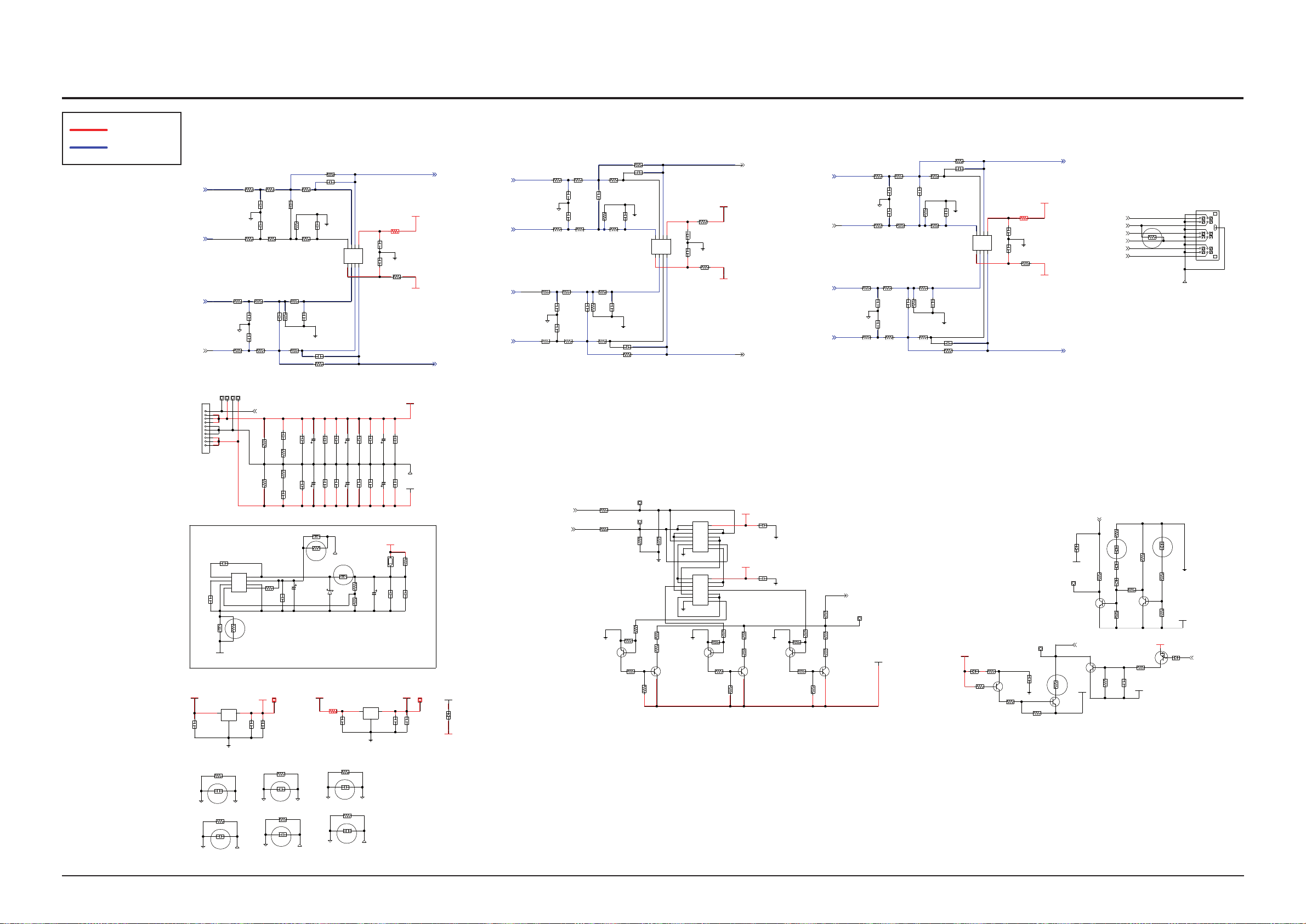
PROTECTION CIRCUIT
2.1CH : INPUT
5.1CH : DELETE
VARIABLE POWER BLOCK
NC
NC
NEW PART
MAX5033
FROM SMPS
NC
NC
NC
NC
1SR154-400TE25
D3.3V
VAA+5V
VSS-5V
680PF
100NF
LPF_OUT_RR
PWM_RR+
PWM_RR-
PWM_RL-
PWM_RL+
LPF_OUT_RL
VSS-5V
VSS-5V
PWM_FL-
PWM_FR-
PWM_FR+
PWM_FL+
LPF_OUT_SW
PWM_SW-
PWM_C-
PWM_C+
PWM_SW+
VAA+5V
LPF_OUT_C
VSS-5V
LPF_OUT_FL
LPF_OUT_FR
R92
1/10W
10OHM
VAA+5V
D3.3V
D3.3V
+PVDD+30V
400V
-PVDD-30V
VSS-5V
-12VA
-5V
VSS-5V
R339
1/10W
0OHM
VAA+5V
+5V
+12VA
GVDD-18V
+PVDD+30V
-PVDD-30V
R88
10OHM
1/10W
VAA+5V
VARIABLE_POWER_REF_V
VARIABLE_POWER_CTRL_A
VARIABLE_POWER_CTRL_B
VARIABLE_POWER_REF_V
CSD_DISCHARGE
/RESET(POWER)
CSD_DISCHARGE
SPK_RL
SPK_C
SPK_FL
SPK_SW
A_GND
50V
100NF
NCC4
DGND
1/4W
0OHM
R64
S_GND
A_GND
A_GND
DGND
50V
100NF
NCC1
1/4W
0OHM
R63
A_GND
50V
100NF
NCC5
S_GND
1/4W
0OHM
R80
A_GND
A_GND
50V
100NF
NCC6
1/4W
0OHM
R86
DGND
50V
100NF
NCC2
1/4W
0OHM
R73
50V
100NF
NCC3
1/4W
0OHM
R85
50V
100NF
C53
KIA7805AF
IC4
1
2
3
50V
100NF
C67
-PVDD-30V
10UH
L16
NC
NCR2
16V
10UF
C73
50V
100NF
C270
IC14
1
2
3
4 5
6
7
8
50V
100NF
C271
10KOHM
R351
5267-10A(ST)
CON4
1
10
2
3
4
5
6
7
8
9
1/10W
47KOHM
R67
100V
100NF
C272
22UF
50V
C273
NC
NCR1
10UH
L17
100V
MBRS1100T3G
ZD4
330UH
L18
S_GND
50V
100NF
C82
50V
100NF
C60
1.5OHM
1/4W
R79
1/4W
1.5OHM
R78
50V
680UF
C168
50V
100NF
C62
50V
100NF
C66
50V
680UF
C221
P1 P2 P5
47KOHM
1/10W
R66
P8
1/10W
1.2KOHM
R3FL
1KOHM
1/10W
R4FL
DGND
50V
2.7NF
C2FL
1/10W
1.2KOHM
R1FL
50V
2.7NF
C1FL
1/10W
1KOHM
R2FL
50V
100NF
C81
50V
100NF
C59
50V
680UF
C167
50V
100NF
C61
50V
100NF
C65
50V
680UF
C220
680OHM
1/10W
R5FL
50V
1.5NF
C3FL
1/10W
2KOHM
R6FL
680OHM
1/10W
R7FL
A_GND
1/10W2KOHM
R8FL
50V680PF
C6FL
50V
680PF
C5FL
S_GND
A_GND
A_GND
50V
100NF
C54
KIA7905F
IC5
1
2
3
50V
100NF
C68
10UF
16V
C74
10KOHM
1/10W
R354
D2
1/10W
22KOHM
R107
A_GND
KST42
Q8
22KOHM
1/10W
R105
1/10W
39KOHM
R106
1/10W
10KOHM
R104
1/10W
75KOHM
R353
22UF
50V
C276
50V
100NF
C274
5000MA
0.01OHM
L19
10UF
25V
C275
0OHM
R355
50V
100NF
C72
50V
100NF C79
50V
680UF
C223
50V
100NF
C239
S_GND
50V
100NFC71
50V
100NFC78
50V
680UF
C222
50V
100NF
C238
1/10W
0OHM
R337
10KOHM
1/10W
R68
VP_CTL_A
1/10W
0OHM
R336
VP_CTL_B
1/10W
1.2KOHM
R3SW
1KOHM
1/10W
R4SW
50V
2.7NF
C2SW
DGND
1/10W
1.2KOHM
R1SW
50V
2.7NF
C1SW
1KOHM
1/10W
R2SW
680OHM
1/10W
R5SW
50V
1.5NF
C3SW
2KOHM
1/10W
R6SW
50V
680PF
C5SW
680OHM
1/10W
R7SW
1/10W
1.2KOHM
R3FR
DGND
1/10W
1.2KOHM
R1FR
50V
2.7NF
C2FR
1KOHM
1/10W
R4FR
1/10W
680OHM
R7FR
2KOHM
1/10W
R6FR
50V
680PF
C5FR
A_GND
50V
2.7NF
C1FR
1/10W
1KOHM
R2FR
50V
1.5NF
C3FR
680OHM
1/10W
R5FR
50V
680PF
C6FR
2KOHM
1/10W
R8FR
S4560
IC7
123
4
567
8
50V
100NF
C92
50V
100NF
C91
10OHM
1/10W
R89
A_GND
1/10W
1.2KOHM
R3C
50V
2.7NF
C2C
1KOHM
1/10W
R4C
1/10W
680OHM
R7C
1/10W
2KOHM
R6C
1/10W
1.2KOHM
R1C
DGND
50V
2.7NF
C1C
1/10W
1KOHM
R2C
50V
1.5NF
C3C
680OHM
1/10W
R5C
KST92
Q9
1/10W
510KOHM
R103
1/10W
390KOHM
R102
A_GND
A_GND
KST42
Q10
1/10W
27KOHM
R116
1/10W
22KOHM
R115
74LCX00MTCX
IC9
1
10
11
12
13
14
2
3
4
5
6
7 8
9
1/10W
22KOHM
R117
KST92
Q11
10KOHM
1/10W
R114
20KOHM
1/10W
R109
1/10W
27KOHM
R108
A_GND
1/10W
22KOHM
R123
KST42
Q12
1/10W
22KOHM
R122
1/10W
22KOHM
R124
KST92
Q13
10KOHM
1/10W
R121
10KOHM
1/10W
R113
10KOHM
1/10W
R112
1/10W
0OHM
R338
VP_REF_V
A_GND
10KOHM
1/10W
R91
A_GND
74LCX00MTCX
IC8
1
10
11
12
13
14
2
3
4
5
6
7 8
9
16V
100NFC102
16V
100NF
C99
A_GND
A_GND
2KOHM
1/10WR8SW
50V
680PF
C6SW
A_GND
3K3<5C10>
1/10W
1.2KOHM
R3RR
50V
2.7NF
C2RR
1KOHM
1/10W
R4RR
DGND
1/10W
1.2KOHM
R1RR
50V
2.7NF
C1RR
1KOHM
1/10W
R2RR
1N4148WS
75V
D3
2SA1037AK
Q15
1/10W
10KOHM
R128
6.8KOHM
1/10W
R125
22OHM
1/10W
R127
47KOHM
1/10W
R138
A_GND
47UF
6.3V
C114
EXT_SD
MMBT2222A
Q17
VSS-5V
1/10W
0OHM
R134
MMBT2222A
Q18
10KOHM
1/10W
R135
47NF
25V
C117
VOLTAGE_PROTECT
1/10W
47KOHM
R74
KST42
Q19
1/10W
27KOHM
R136
18V
GDZ18B-V
ZD2
VSS-5V
8.2KOHM
1/10W
R141
DTA114EUA
Q5
1N4148WS
75V
D31
1/10W
47KOHM
R143
KST42
Q20
10KOHM
1/10W
R139
1/10W
47KOHM
R142
-PVDD-30V
680OHM
1/10W
R5RR
50V
1.5NF
C3RR
2KOHM
1/10W
R6RR
1/10W
680OHM
R7RR
1/10W2KOHMR8RR
50V680PFC6RR
50V
680PF
C5RR
A_GND
75V
1N4148WS
D30
18V
GDZ18B-V
ZD1
SDZ9V1G
9.1V
ZD5
1/10W
10KOHM
R137
47KOHM
1/10W
R140
SDZ9V1G
9.1V
ZD3
S_GND
50V
680PF
C5C
A_GND
S4560
IC10
123
4 5
678
50V
100NF
C94
50V
100NF
C93
50V
680PF
C6C
2KOHM
1/10W
R8C
10OHM
1/10W
R70
A_GND
10OHM
1/10W
R69
1/10W
1.2KOHM
R3RL
50V
2.7NF
C2RL
DGND
50V
2.7NF
C1RL
1/10W
1.2KOHM
R1RL
1/10W
1KOHM
R4RL
1/10W
680OHM
R7RL
1/10W
2KOHM
R6RL
50V
C5RL
A_GND
1KOHM
1/10W
R2RL
50V
1.5NF
C3RL
1/10W
680OHM
R5RL
50V
680PF
C6RL
1/10W
2KOHMR8RL
S4560
IC11
1
2
3
4 5
6
7
8
50V
C95
50V
100NF
C33
1/10W
10OHM
R71
A_GND
SPK_RR
SPK_FR
1W
0OHM
NRR4
S_GND
SP1
1
10
11
12
2
3
4
5
6
7
8
9
MGND1
IN2+
VEE
OUT2
VCC
IN2-
IN1+
IN1-
OUT1
E
B
C
E
B
C
E
B
C
GND
OUTIN
GND
OUTIN
E
C
B
E
B
C
E
B
C
E
B
C
/O3GND
A3
B3/O1
B1
/O2A1
A2
VCC
B2/O0
B0
A0
/O3GND
A3
B3/O1
B1
/O2A1
A2
VCC
B2/O0
B0
A0
E
B
C
E
B
C
E
B
C
BST LX
VD
SGND GND
VIN
FB ON/OFF#
-
+
+
-
-++
-
+
-
-
+
IN2+
VEE
OUT2
VCC
IN2-
IN1+
IN1-
OUT1
IN2+
VEE
OUT2
VCC
IN2-
IN1+
IN1-
OUT1
E
B
C
E
B
C
PROTECTION CIRCUIT
2.1CH : INPUT
5.1CH : DELETE
VARIABLE POWER BLOCK
NC
NC
NEW PART
MAX5033
FROM SMPS
NC
NC
NC
NC
1SR154-400TE25
D3.3V
VAA+5V
VSS-5V
680PF
100NF
VSS-5V
VAA+5V
VSS-5V
1/10W
10OHM
VAA+5V
D3.3V
D3.3V
+PVDD+30V
400V
-PVDD-30V
VSS-5V
-12VA VSS-5V
1/10W
0OHM
VAA+5V
+12VA
GVDD-18V
+PVDD+30V
-PVDD-30V
10OHM
1/10W
VAA+5V
A_GND
50V
100NF
DGND
1/4W
0OHM
S_GND
A_GND
A_GND
DGND
50V
100NF
1/4W
0OHM
A_GND
50V
100NF
S_GND
1/4W
0OHM
A_GND
A_GND
50V
100NF
1/4W
0OHM
DGND
50V
100NF
1/4W
0OHM
50V
100NF
1/4W
0OHM
50V
100NF
KIA7805AF
50V
100NF
-PVDD-30V
10UH
NC
16V
10UF
50V
100NF
50V
100NF
10KOHM
5267-10A(ST)
1/10W
47KOHM
100V
100NF
22UF
50V
NC
10UH
100V
MBRS1100T3G
330UH
S_GND
50V
100NF
50V
100NF
1.5OHM
1/4W
1/4W
1.5OHM
50V
680UF
50V
100NF
50V
100NF
50V
680UF
47KOHM
1/10W
1/10W
1.2KOHM 1KOHM
1/10W
DGND
50V
2.7NF
1/10W
1.2KOHM
50V
2.7NF
1/10W
1KOHM
50V
100NF
50V
100NF
50V
680UF
50V
100NF
50V
100NF
50V
680UF
680OHM
1/10W
50V
1.5NF
1/10W
2KOHM
680OHM
1/10W
A_GND
1/10W2KOHM
50V680PF
50V
680PF
S_GND
A_GND
A_GND
50V
100NF
KIA7905F
50V
100NF
10UF
16V
10KOHM
1/10W
1/10W
22KOHM
A_GND
KST42
22KOHM
1/10W
1/10W
39KOHM
1/10W
10KOHM
1/10W
75KOHM
22UF
50V
50V
100NF
5000MA
0.01OHM
10UF
25V
0OHM
50V
100NF
50V
100NF
50V
680UF
50V
100NF
S_GND
50V
100NF
50V
100NF
50V
680UF
50V
100NF
1/10W
0OHM
10KOHM
1/10W
1/10W
0OHM
1/10W
1.2KOHM
1KOHM
1/10W
50V
2.7NF
DGND
1/10W
1.2KOHM
50V
2.7NF
1KOHM
1/10W
680OHM
1/10W
50V
1.5NF
2KOHM
1/10W
50V
680PF
680OHM
1/10W
1/10W
1.2KOHM
DGND
1/10W
1.2KOHM
50V
2.7NF
1KOHM
1/10W
1/10W
680OHM
2KOHM
1/10W
50V
680PF
A_GND
50V
2.7NF
1/10W
1KOHM
50V
1.5NF
680OHM
1/10W
50V
680PF
2KOHM
1/10W
S4560
50V
100NF
50V
100NF
10OHM
1/10W
A_GND
1/10W
1.2KOHM
50V
2.7NF
1KOHM
1/10W 1/10W
680OHM
1/10W
2KOHM
1/10W
1.2KOHM
DGND
50V
2.7NF
1/10W
1KOHM
50V
1.5NF
680OHM
1/10W
KST92
1/10W
510KOHM
1/10W
390KOHM
A_GND
A_GND
KST42
1/10W
27KOHM
1/10W
22KOHM
74LCX00MTCX
1/10W
22KOHM
KST92
10KOHM
1/10W
20KOHM
1/10W 1/10W
27KOHM
A_GND
1/10W
22KOHM
KST42
1/10W
22KOHM
1/10W
22KOHM
KST92
10KOHM
1/10W
10KOHM
1/10W
10KOHM
1/10W
1/10W
0OHM
A_GND
10KOHM
1/10W
A_GND
74LCX00MTCX
16V
100NF
16V
100NF
A_GND
A_GND
2KOHM
1/10W
50V
680PF
A_GND
1/10W
1.2KOHM
50V
2.7NF
1KOHM
1/10W
DGND
1/10W
1.2KOHM
50V
2.7NF
1KOHM
1/10W
1N4148WS
75V
2SA1037AK
1/10W
10KOHM
6.8KOHM
1/10W
22OHM
1/10W
47KOHM
1/10W
A_GND
47UF
6.3V
MMBT2222A
VSS-5V
1/10W
0OHM
MMBT2222A
10KOHM
1/10W
47NF
25V
1/10W
47KOHM
KST42
1/10W
27KOHM
18V
GDZ18B-V
VSS-5V
8.2KOHM
1/10W
DTA114EUA
1N4148WS
75V
1/10W
47KOHM
KST42
10KOHM
1/10W
1/10W
47KOHM
-PVDD-30V
680OHM
1/10W
50V
1.5NF
2KOHM
1/10W
1/10W
680OHM
1/10W2KOHM
50V680PF
50V
680PF
A_GND
75V
1N4148WS
18V
GDZ18B-V
SDZ9V1G
9.1V
1/10W
10KOHM
47KOHM
1/10W
SDZ9V1G
9.1V
S_GND
50V
680PF
A_GND
S4560
50V
100NF
50V
100NF
50V
680PF
2KOHM
1/10W
10OHM
1/10W
A_GND
10OHM
1/10W
1/10W
1.2KOHM
50V
2.7NF
DGND
50V
2.7NF
1/10W
1.2KOHM
1/10W
1KOHM
1/10W
680OHM
1/10W
2KOHM
50V
A_GND
1KOHM
1/10W
50V
1.5NF
1/10W
680OHM
50V
680PF
1/10W
2KOHM
S4560
50V 50V
100NF
1/10W
10OHM
A_GND
1W
0OHM
S_GND
R92
-5V
R339
+5V
R88
NCC4
R64
NCC1
R63
NCC5
R80
NCC6
R86
NCC2
R73
NCC3
R85
C53
IC4
C67
L16
NCR2
C73
C270
IC14
C271
R351
CON4
R67
C272
C273
NCR1
L17
ZD4
L18
C82
C60
R79 R78
C168
C62
C66
C221
P1 P2 P5
R66
P8
R3FL
R4FL
C2FL
R1FL
C1FL
R2FL
C81
C59
C167
C61
C65
C220
R5FL
C3FL
R6FL
R7FL
R8FL
C6FL
C5FL
C54
IC5
C68
C74
R354
D2
R107
Q8
R105
R106
R104
R353
C276
C274
L19
C275
R355
C72
C79
C223
C239
C71
C78
C222
C238
R337
R68
VP_CTL_A
R336
VP_CTL_B
R3SW
R4SW
C2SW
R1SW
C1SW
R2SW
R5SW
C3SW
R6SW
C5SW
R7SW
R3FR
R1FR
C2FR
R4FR R7FR
R6FR
C5FR
C1FR
R2FR
C3FR
R5FR
C6FR
R8FR
IC7
C92 C91
R89
R3C
C2C
R4C R7C
R6C
R1C
C1C
R2C
C3C
R5C
Q9
R103
R102
Q10
R116
R115
IC9
R117
Q11
R114
R109
R108
R123
Q12
R122
R124
Q13
R121
R113 R112 R338
VP_REF_V
R91
IC8
C102
C99
R8SW
C6SW
R3RR
C2RR
R4RR
R1RR
C1RR
R2RR
D3
Q15
R128
R125
R127
R138
C114
EXT_SD
Q17
R134
Q18
R135
C117
VOLTAGE_PROTECT
R74
Q19
R136
ZD2
R141
Q5
D31
R143
Q20
R139
R142
R5RR
C3RR
R6RR
R7RR
R8RR
C6RR
C5RR
D30
ZD1
ZD5
R137
R140
ZD3
C5C
IC10
C94 C93
C6C
R8C
R70
R69
R3RL
C2RL C1RL
R1RL
R4RL R7RL
R6RL
C5RL
R2RL
C3RL
R5RL
C6RL
R8RL
IC11
C95 C33
R71
NRR4
SP1
3K3<5C10>
LPF_OUT_RR
PWM_RR+
PWM_RR-
PWM_RL-
PWM_RL+
LPF_OUT_RL
PWM_FL-
PWM_FR-
PWM_FR+
PWM_FL+
LPF_OUT_SW
PWM_SW-
PWM_C-
PWM_C+
PWM_SW+
LPF_OUT_C
LPF_OUT_FR
VARIABLE_POWER_REF_V
VARIABLE_POWER_CTRL_A
VARIABLE_POWER_CTRL_B
VARIABLE_POWER_REF_V
CSD_DISCHARGE
/RESET(POWER)
CSD_DISCHARGE
SPK_RL
SPK_C
SPK_FL
SPK_SW
SPK_RR
SPK_FR
1
2
3
1
2
3
4 5
6
7
8
1
10
2
3
4
5
6
7
8
9
1
2
3
123
4
567
8
1
10
11
12
13
14
2
3
4
5
6
7 8
9
1
10
11
12
13
14
2
3
4
5
6
7 8
9
123
4 5
678
1
2
3
4 5
6
7
8
1
10
11
12
2
3
4
5
6
7
8
9
MGND1
IN2+
VEE
OUT2
VCC
IN2-
IN1+
IN1-
OUT1
E
B
C
E
B
C
E
B
C
GND
OUTIN
GND
OUTIN
E
C
B
E
B
C
E
B
C
E
B
C
DNG 3O/
A3
1O/ 3B
B1
1A 2O/
A2
VCC
0O/ 2B
B0
A0
DNG 3O/
A3
1O/ 3B
B1
1A 2O/
A2
VCC
0O/ 2B
B0
A0
E
B
C
E
B
C
E
B
C
BST LX
VD
SGND GND
VIN
FB ON/OFF#
-
+
+
-
-++
-
+
-
-
+
IN2+
VEE
OUT2
VCC
IN2-
IN1+
IN1-
OUT1
IN2+
VEE
OUT2
VCC
IN2-
IN1+
IN1-
OUT1
E
B
C
E
B
C
7-5 AMP-2
Schematic Diagram
POWER
AUDIO
This Document can not be used without Samsung’s authorization.
Samsung Electronics 7-5
Page 96

NC
NC
NC
NC
NC
DAED TIME : 45NS
NC
NC
OC
-28A
2.1CH : INPUT
5.1CH : DELETE
LPF_OUT_FL
10UF
16V
C118
LPF_OUT_FR
10UF
16V
C120
OUTER_FEEDBACK_FL
INNER_FEEDBACK_FL
SPK_FL
INNER_FEEDBACK_FR
OUTER_FEEDBACK_FR
GVDD-18V
OUTER_FEEDBACK_RL
INNER_FEEDBACK_RL
SPK_RL
SPK_FR
50V
1NF
C129
INNER_FEEDBACK_FR
OUTER_FEEDBACK_FR
LPF_OUT_SW
50V1NF
OUTER_FEEDBACK_RL
INNER_FEEDBACK_RL
LPF_OUT_RL
R169
1.5KOHM
1/10W
10KOHM
1/10W
50V
D32
S1G
400V
GVDD-18V
10OHM
27
36
D10
C137
1KOHM
R176
5.6KOHM
R173
1/10W
PRF21BB471QB5RA
1/10W
50V
+PVDD+30V
R225
47KOHM
1/10W
L10
UNDEFINED
C164
50V
2.2NF
R226
2.2KOHM
1/4W
S_GND
R227
1/10W
47KOHM
C161
100NF
250V
C158
100V
470NF
D33
400V
S1G
R222
10OHM
1W
R72
1/10W
27KOHM
R219
33KOHM
1/10W
D34
S1G
400V
C155
100NF
100V
C149
100NF
C143
100NF
R213
1OHM
1/10W
S_GND
765
4
3
2
1
JFET1
IRF6645
GVDD-18V
R201
10OHM
1/10W
R202
10OHM
1/10W
R207
10OHM
1/10W
S_GND
C150
100NF
50V
C144
100NF
50V
R214
1OHM
1/10W
C156
100V
100NF
C151
100NF
50V
C145
100NF
50V
S_GND
R215
1OHM
1/10W
7
6
5
4
3
2
1
JFET2
IRF6645
R208
1/10W
10OHM
7
6
5
43
2
1
JFET3
IRF6645
R203
1/10W
10OHM
R204
10OHM
1/10W
C165
50V
2.2NF
S_GND
R228
2.2KOHM
1/4W
C162
250V
100NF
R223
10OHM
1W
C159
100V
470NF
D35
400V
S1G
L11
UNDEFINED
R75
27KOHM
1/10W
R220
1/10W
33KOHM
D36
400V
S1G
C166
50V
2.2NF
R229
1/10W
47KOHM
R230
2.2KOHM
1/4W
C163
100NF
250V
R224
1W
10OHM
S_GND
C160
100V
470NF
L12
UNDEFINED
D37
400V
S1G
C157
100NF
100V
R76
27KOHM
1/10W
R221
33KOHM
1/10W
S_GND
C152
100NF
50V
C146
100NF
50V
R216
1/10W
1OHM
C153
50V
100NF
C147
100NF
50V
7
6
5
43
2
1
JFET4
IRF6645
R209
10OHM
1/10W
R210
1/10W
10OHM
R205
10OHM
1/10W
D12
200V
ES1D-13-F
R217
1/10W
1OHM
S_GND
S_GND
C154
100NF
50V
C148
100NF
50V
7
6
5
4
3
2
1
JFET5
IRF6645
R218
1/10W
1OHM
7
6543
2
1
JFET6
IRF6645
R206
10OHM
1/10W
R211
10OHM
1/10W
R200
1/10W
6.8KOHM
R212
10OHM
1/10W
LED7
SML-310LT-T86
R29
9.1KOHM
D7
BAV20WS-7-F
150V
ES1D-13-F
200V
R195
9.1KOHM
1/10W
C140
10UF
25V
R187
820OHM
1/10W
R192
1/10W
R183
1/10W
10KOHM
A_GND
R186
20KOHM
1/10W
NCC8
50V
470PF
NCC7
50V
470PF
R340
1KOHM
1/10W
R198
1/10W
6.8KOHM
LED5
SML-310LT-T86
A_GND
D8
BAV20WS-7-F
150V
R62
9.1KOHM
1/10W
D11
200V
ES1D-13-F
R196
9.1KOHM
1/10W
C141
25V
10UF
R193
10KOHM
1/10W
R188
20KOHM
1/10W
R189
1/10W
820OHM
NCC10
470PF
50V
R184
1/10W
10KOHM
NCC9
470PF
50V
R341
1KOHM
1/10W
C25 10UF
25V
R182
1/10W
10OHM
OTP_FL
R177
PRF21BB471QB5RA
R174
1KOHM
OTP_C
R175
R172
4.7KOHM
1/10W
C138
10NF
50V
R178
1/10W
1KOHM
R181
1/10W
10NF
50V
C135
10UF
25V
-PVDD-30V
MGND1
9
876
5
48
47
46
45
44
43
42
41
40
4
39
38
37
3534333231
303292826
25
24
23
22
21
20
2
19
18
17
16
15
14
13
12
11
10
1
IC12
1/10W
GVDD-18V
1/10W
R170
8.2KOHM
R167
1/10W
100OHM
R199
1/10W
6.8KOHM
LED6
SML-310LT-T86
R65
9.1KOHM
1/10W
R197
9.1KOHM
1/10W
D9
BAV20WS-7-F
150V
R194
1/10W
10KOHM
A_GND
R190
1/10W
20KOHM
NCC12
50V
470PF
NCC11
50V
470PF
R191
1/10W
820OHM
R185
1/10W
10KOHM
R342
1KOHM
1/10W
DCP1
C136
47UF
6.3V
C142
25V
10UF
LED4
SML-310LT-T86
LED3
SML-310LT-T86
LED2
SML-310LT-T86
LED1
SML-310LT-T86
R3
1/10W
6.8KOHM
R163
1/10W
6.8KOHM
C241
47UF
6.3V
A_GND
R171
47KOHM
1/10W
R166
1/10W
6.8KOHM
R160 0OHM 1/10W
R165
1/10W
6.8KOHM
A_GND
R162
1/10W
220OHM
C134
10UF
25V
C127
1NF
50V
C124
50V
1NF
R153
390OHM
1/10W
R147 100KOHM
1/10W
R148
1/10W
47KOHM
C121
1NF
50V
C128
1NF
50V
C125
C132
100NF
50V
C133
100NF
50V
R154
390OHM
1/10W
R149 100KOHM1/10W
R150
1/10W
47KOHM
C122
1NF
50V
R156
4.7OHM
1/10W
R144
2.2KOHM
1/10W
C130
1UF
25V
C131
1UF
25V
A_GND
R157
4.7OHM
1/10W
R145
2.2KOHM
1/10W
C119
10UF
16V
OF_FLIF_FL
D5
75V
1N4148WS
C126
1NF 50V
R151
100KOHM
1/10W
R152
1/10W
47KOHM
R155
390OHM
1/10W
C123
1NF
50V
NRR3
0OHM
1/10W
LPF_OUT_FR
R146
2.2KOHM
1/10W
DC_PROTECTION_1
DC_PROTECTION_1
DC_PROTECTION_1
OUTER_FEEDBACK_FL
INNER_FEEDBACK_FL
DC_PROTECTION_1
_SD(POWER)
CSD_DISCHARGE
VAA+5V
VSS-5V
VSS-5V
VAA+5V
+PVDD+30V
GVDD-18V
+PVDD+30V
-PVDD-30V
-PVDD-30V
-PVDD-30V
-PVDD-30V
CLIP2
NC
COMP1
DCP
FAULT
CLIP1
CLIP3
VS1
NC
VS2
HO2
VB2
CSH2
VCC2
LO2
LO1
NC
CSH1
VB1
HO1
HO3
VB3
CSH3
NC
LO3
COM2
VCC
COM
OTP3
OTP2
OTP1
NC
VS3
GND
VSS
GND
CSD
COMP2
IN1
VAA
IN2
IN3
DS
COMP3
NC
OCSET
VREF
DT
NC
NC
NC
NC
NC
DAED TIME : 45NS
NC
NC
OC
-28A
2.1CH : INPUT
5.1CH : DELETE
10UF
16V
10UF
16V
GVDD-18V
50V
1NF
FN1 V05
1.5KOHM
1/10W
10KOHM
1/10W
50V
S1G
400V
GVDD-18V
10OHM
1KOHM
5.6KOHM
1/10W
PRF21BB471QB5RA
1/10W
50V
+PVDD+30V
47KOHM
1/10W
UNDEFINED
50V
2.2NF
2.2KOHM
1/4W
S_GND
1/10W
47KOHM
100NF
250V
100V
470NF
400V
S1G
10OHM
1W
1/10W
27KOHM
33KOHM
1/10W
S1G
400V
100NF
100V
100NF
100NF
1OHM
1/10W
S_GND
IRF6645
GVDD-18V
10OHM
1/10W
10OHM
1/10W
10OHM
1/10W
S_GND
100NF
50V
100NF
50V
1OHM
1/10W
100V
100NF
100NF
50V
100NF
50V
S_GND
1OHM
1/10W
IRF6645
1/10W
10OHM
IRF6645
1/10W
10OHM
10OHM
1/10W
50V
2.2NF
S_GND
2.2KOHM
1/4W
250V
100NF
10OHM
1W
100V
470NF
400V
S1G
UNDEFINED
27KOHM
1/10W
1/10W
33KOHM
400V
S1G
50V
2.2NF
1/10W
47KOHM2.2KOHM
1/4W
100NF
250V
1W
10OHM
S_GND
100V
470NF
UNDEFINED
400V
S1G
100NF
100V
27KOHM
1/10W
33KOHM
1/10W
S_GND
100NF
50V
100NF
50V
1/10W
1OHM
50V
100NF
100NF
50V
IRF6645
10OHM
1/10W
1/10W
10OHM
10OHM
1/10W
200V
ES1D-13-F
1/10W
1OHM
S_GND
S_GND
100NF
50V
100NF
50V
IRF6645
1/10W
1OHM
IRF6645
10OHM
1/10W
10OHM
1/10W
1/10W
6.8KOHM
10OHM
1/10W
SML-310LT-T86
9.1KOHM
BAV20WS-7-F
150V
ES1D-13-F
200V
9.1KOHM
1/10W
10UF
25V
820OHM
1/10W
1/10W
1/10W
10KOHM
A_GND
20KOHM
1/10W
50V
470PF
50V
470PF
1KOHM
1/10W
1/10W
6.8KOHM
SML-310LT-T86
A_GND
BAV20WS-7-F
150V
9.1KOHM
1/10W
200V
ES1D-13-F
9.1KOHM
1/10W
25V
10UF
10KOHM
1/10W
20KOHM
1/10W
1/10W
820OHM
470PF
50V
1/10W
10KOHM
470PF
50V
1KOHM
1/10W
10UF
25V
1/10W
10OHM
PRF21BB471QB5RA
1KOHM
4.7KOHM
1/10W
10NF
50V
1/10W
1KOHM
1/10W
10NF 50V
10UF
25V
-PVDD-30V
1/10W
GVDD-18V
1/10W
8.2KOHM
1/10W
100OHM
1/10W
6.8KOHM
SML-310LT-T86
9.1KOHM
1/10W
9.1KOHM
1/10W
BAV20WS-7-F
150V
1/10W
10KOHM
A_GND
1/10W
20KOHM
50V
470PF
50V
470PF
1/10W
820OHM
1/10W
10KOHM
1KOHM
1/10W
47UF
6.3V
25V
10UF
SML-310LT-T86
SML-310LT-T86
SML-310LT-T86
SML-310LT-T86
1/10W
6.8KOHM
1/10W
6.8KOHM
47UF
6.3V
A_GND
47KOHM
1/10W
1/10W
6.8KOHM
0OHM 1/10W
1/10W
6.8KOHM
A_GND
1/10W
220OHM
10UF
25V
1NF
50V
50V
1NF
390OHM
1/10W
100KOHM
1/10W
1/10W
47KOHM
1NF
50V
1NF
50V
100NF
50V
100NF
50V
390OHM
1/10W
100KOHM 1/10W
1/10W
47KOHM
1NF
50V
4.7OHM
1/10W
2.2KOHM
1/10W
1UF
25V
1UF
25V
A_GND
4.7OHM
1/10W
2.2KOHM
1/10W
10UF
16V
75V
1N4148WS
1NF 50V
100KOHM
1/10W
1/10W
47KOHM
390OHM
1/10W
1NF
50V
0OHM
1/10W
2.2KOHM
1/10W
VAA+5V
VSS-5V
VSS-5V
VAA+5V
+PVDD+30V
GVDD-18V
+PVDD+30V
-PVDD-30V
-PVDD-30V
-PVDD-30V
-PVDD-30V
C118
C120
C129
R169
D32
D10
C137
R176
R173
R225
L10
C164
R226
R227
C161
C158
D33
R222
R72
R219
D34
C155
C149
C143
R213
JFET1
R201
R202
R207
C150
C144
R214
C156
C151
C145R215
JFET2
R208
JFET3
R203
R204
C165
R228
C162
R223
C159
D35
L11
R75
R220
D36
C166
R229
R230
C163
R224
C160
L12
D37
C157
R76
R221
C152
C146
R216
C153
C147
JFET4
R209
R210
R205
D12
R217
C154
C148
JFET5
R218
JFET6
R206
R211
R200
R212
LED7
R29
D7
R195C140
R187
R192
R183
R186
NCC8
NCC7
R340
R198
LED5
D8
R62
D11
R196C141
R193
R188
R189
NCC10
R184
NCC9
R341
C25
R182
OTP_FL
R177
R174
OTP_C
R175
R172
C138
R178
R181
C135
IC12
R170
R167
R199
LED6
R65
R197
D9
R194
R190
NCC12
NCC11
R191
R185
R342
DCP1
C136
C142
LED4
LED3
LED2
LED1
R3
R163
C241
R171
R166
R160
R165
R162
C134
C127
C124
R153
R147
R148
C121
C128
C125
C132C133
R154
R149
R150
C122
R156
R144
C130C131
R157
R145
C119
OF_FLIF_FL
D5
C126
R151
R152
R155C123
NRR3
LPF_OUT_FR
R146
LPF_OUT_FL
LPF_OUT_FR
OUTER_FEEDBACK_FL
INNER_FEEDBACK_FL
SPK_FL
INNER_FEEDBACK_FR
OUTER_FEEDBACK_FR
OUTER_FEEDBACK_RL
INNER_FEEDBACK_RL
SPK_RL
SPK_FR
INNER_FEEDBACK_FR
OUTER_FEEDBACK_FR
LPF_OUT_SW
OUTER_FEEDBACK_RL
INNER_FEEDBACK_RL
LPF_OUT_RL
DC_PROTECTION_1
DC_PROTECTION_1
DC_PROTECTION_1
OUTER_FEEDBACK_FL
INNER_FEEDBACK_FL
DC_PROTECTION_1
_SD(POWER)
CSD_DISCHARGE
27
36
7
654
321
7
654
3
2
1
7
6
5
4
3
2
1
7
6
5
4
3
2
1
7
6
5
4
3
2
1
7
6
5
4
3
2
1
MGND1
9
876
5
48
47
46
45
44
43
42
41
40
4
39
38
37
3534333231
303292826
25
24
23
22
21
20
2
19
18
17
16
15
14
13
12
11
10
1
CLIP2
NC
COMP1
DCP
FAULT
CLIP1
CLIP3
VS1
NC
VS2
HO2
VB2
CSH2
VCC2
LO2
LO1
NC
CSH1
VB1
HO1
HO3
VB3
CSH3
NC
LO3
COM2
VCC
COM
OTP3
OTP2
OTP1
NC
VS3
GND
VSS
GND
CSD
COMP2
IN1
VAA
IN2
IN3
DS
COMP3
NC
OCSET
VREF
DT
Schematic Diagram
7-6 AMP-3
POWER
AUDIO
This Document can not be used without Samsung’s authorization.
7-6 Samsung Electronics
Page 97

NC
NC
NC
NC
NC
NC
NC
DAED TIME : 45NS
-28A
OC
SPK_RR
OUTER_FEEDBACK_SW
INNER_FEEDBACK_SW
SPK_SW
GVDD-18V
GVDD-18V
GVDD-18V
SPK_C
INNER_FEEDBACK_C
OUTER_FEEDBACK_C
OUTER_FEEDBACK_SW
INNER_FEEDBACK_SW
VSS-5V
LPF_OUT_SW
C173
10UF
16V
OUTER_FEEDBACK_RR
INNER_FEEDBACK_RR
LPF_OUT_RR
INNER_FEEDBACK_C
OUTER_FEEDBACK_C
LPF_OUT_C
-PVDD-30V
+PVDD+30V
-PVDD-30V
+PVDD+30V
-PVDD-30V
+PVDD+30V
GVDD-18V
-PVDD-30V
VAA+5V
VSS-5V
VAA+5V
CSD_DISCHARGE
_SD(POWER)
DC_PROTECTION_2
DC_PROTECTION_2
DC_PROTECTION_2
INNER_FEEDBACK_RR
OUTER_FEEDBACK_RR
DC_PROTECTION_2
1/10W
2.2KOHM
R233
LPF_OUT_SW
10UF
16V
C172
1/10W
2.2KOHM
R232
50V
1NF
C176
47KOHM
1/10W
R239
1/10W
100KOHMR238
1/10W
390OHM
R242
1/10W
4.7OHM
R244
A_GND
25V
1UF
C184
50V
1NF
C175
1/10W
390OHM
R241
1/10W
47KOHMR237
1/10W
100KOHMR236
50V
100NF
C186
75V
1N4148WS
D13
1NF 50V
C179
50V
1NF
C182
1/10W
220OHM
R249
IF_FR OF_FR
50V1NFC178
1NF
50V
C181
1/10W
4.7OHM
R243
16V
10UF
C171
1/10W
2.2KOHM
R231
1UF
25V
C183
50V
100NF
C185
50V
1NF
C174
1/10W
390OHM
R240
1/10W
47KOHM
R235
1/10W
100KOHM
R234
1NF
50V
C180
50V1NF
C177
1/10W
100OHMR254
1/10W
8.2KOHM
R257
1.5KOHM
1/10W
R256
1/10W0OHM
R247
A_GND
47KOHM
1/10W
R258
47UF
6.3V
C240
47UF
6.3V
C189
DCP2
10UF
25V
C187
A_GND
6.8KOHM
1/10W
R252
SML-310LT-T86
LED8
1/10W
6.8KOHMR253
SML-310LT-T86
LED9
IC13
1
10
11
12
13
14
15
16
17
18
19
2
20
21
22
23
24
25
262728
29
3
30313233343536
37
38
39
4
40
41
42
43
44
45
46
47
48
5
678
9
MGND1
1/10W
6.8KOHMR250
SML-310LT-T86
LED10
6.8KOHM
1/10W
R251
SML-310LT-T86
LED11
-PVDD-30V
10KOHM
1/10W
R272
1/10W
1KOHM
R345
820OHM
1/10W
R278
SML-310LT-T86
LED14
6.8KOHM
1/10W
R287
10OHM
1/10W
R299
25V
10UF
C300
10UF
25V
C195
10KOHM
1/10W
R281
150V
BAV20WS-7-F
D17
1/10W
9.1KOHM
R284
1/10W
9.1KOHM
R87
ES1D-13-F
200V
D20
1/10W
10OHM
R298
10OHM
1/10W
R293
10OHM
1/10W
R292
50V
470PF
NCC17
470PF
50V
NCC18
1/10W
20KOHM
R277
A_GND
10UF
25V
C192
10KOHM
1/10W
R271
1/10W
820OHM
R276
SML-310LT-T86
LED13
6.8KOHM
1/10W
R286
10OHM
1/10W
R297
10UF
25V
C194
1/10W
10KOHM
R280
BAV20WS-7-F
150V
D16
1/10W
9.1KOHM
R283
200V
ES1D-13-F
D19
1/10W
9.1KOHM
R90
10OHM
1/10W
R296
10OHM
1/10W
R291
10OHM
1/10W
R290
IRF6645
JFET12
1
2
3
4
5
6
7
IRF6645
JFET11
1
2
3 4
5
6
7
1OHM
1/10W
R305
50V
100NF
C201
50V
100NF
C207
S_GND
1/10W
33KOHM
R308
27KOHM
1/10W
R95
S_GND
1OHM
1/10W
R304
100V
100NF
C210
50V
100NF
C200
50V
100NF
C206
IRF6645
JFET10
1
2
3
4
567
1/10W
1OHM
R48
50V
100NF
C199
IRF6645
JFET9
1
2
3 4
567
S_GND
1OHM
1/10W
R302
50V
100NF
C198
50V
100NF
C205
S_GND
1/10W
33KOHM
R307
1/10W
27KOHM
R94
100V
100NF
C209
50V
100NF
C204
UNDEFINED
L14
S1G
400V
D43
470NF
100V
C213
10OHM
1W
R311
100NF
250V
C216
1/4W
2.2KOHM
R317
UNDEFINED
L15
S1G
400V
D42
47KOHM
1/10W
R316
S_GND
50V
2.2NF
C219
S1G
400V
D41
470NF
100V
C212
1W
10OHM
R310
250V
100NF
C215
1/4W
2.2KOHM
R315
S1G
400V
D40
47KOHM
1/10W
R314
S_GND
2.2NF
50V
C218
10UF
25V
C188
1/10W
5.6KOHM
R260
GVDD-18V
1/10W
4.7KOHM
R259
1/10W
1KOHM
R263
PRF21BB471QB5RA
R262
50V
10NF
C190
OTP_SW
1KOHM
1/10W
R261
10OHM
1/10W
R268
1/10W
10OHM
R269
1/10W
1KOHM
R265
50V
10NF
C191
OTP_FR
1/10W
1KOHM
R343
470PF
50V
NCC13
1/10W
1KOHM
R344
470PF
50V
NCC15
1/10W
20KOHM
R275
50V
470PF
NCC16
A_GND
10KOHM
1/10W
R270
10KOHM
1/10W
R279
SML-310LT-T86
LED12
6.8KOHM
1/10W
R285
1/10W
10OHM
R295
25V
10UF
C193
1/10W
9.1KOHM
R282
200V
ES1D-13-F
D18
1/10W
9.1KOHM
R84
10OHM
1/10W
R294
1/10W
10OHM
R289
1/10W
10OHM
R288
470PF
50V
NCC14
20KOHM
1/10W
R273
A_GND
1/10W
820OHM
R274
150V
BAV20WS-7-F
D15
IRF6645
JFET8
1
2
3 4
5
6
7
1OHM
1/10W
R301
50V
100NF
C197
IRF6645
JFET7
123 4
5
6
7
S_GND
1OHM
1/10W
R300
50V
100NF
C196
50V
100NF
C203
1/10W
33KOHM
R82
S_GND
50V
100NF
C202
100NF
100V
C208
1/10W
27KOHM
R93
UNDEFINED
L13
100V
470NF
C211
400V
S1G
D39
1W
10OHM
R309
S_GND
1/4W
2.2KOHM
R313
50V
2.2NF
C217
250V
100NF
C214
S1G
400V
D38
1/10W
47KOHM
R312
CLIP2
NC
COMP1
DCP
FAULT
CLIP1
CLIP3
VS1
NC
VS2
HO2
VB2
CSH2
VCC2
LO2
LO1
NC
CSH1
VB1
HO1
HO3
VB3
CSH3
NC
LO3
COM2
VCC
COM
OTP3
OTP2
OTP1
NC
VS3
GND
VSS
GND
CSD
COMP2
IN1
VAA
IN2
IN3
DS
COMP3
NC
OCSET
VREF
DT
NC
NC
NC
NC
NC
NC
NC
DAED TIME : 45NS
-28A
OC
GVDD-18V
GVDD-18V
GVDD-18V
VSS-5V
10UF
16V
-PVDD-30V
+PVDD+30V
-PVDD-30V
+PVDD+30V
-PVDD-30V
+PVDD+30V
GVDD-18V
-PVDD-30V
VAA+5V
VSS-5V
VAA+5V
1/10W
2.2KOHM
10UF
16V
1/10W
2.2KOHM
50V
1NF
47KOHM
1/10W
1/10W
100KOHM
1/10W
390OHM
1/10W
4.7OHM
A_GND
25V
1UF
50V
1NF
1/10W
390OHM
1/10W
47KOHM
1/10W
100KOHM
50V
100NF
75V
1N4148WS
1NF 50V
50V
1NF
1/10W
220OHM
FN1 V05
1NF
50V
1/10W
4.7OHM
16V
10UF
1/10W
2.2KOHM
1UF
25V
50V
100NF
50V
1NF
1/10W
390OHM
1/10W
47KOHM
1/10W
100KOHM
1NF
50V
FN1 V05
1/10W
100OHM
1/10W
8.2KOHM 1.5KOHM
1/10W
1/10W0OHM
A_GND
47KOHM
1/10W
47UF
6.3V
47UF
6.3V
10UF
25V
A_GND
6.8KOHM
1/10W
SML-310LT-T86
1/10W
6.8KOHM
SML-310LT-T86
1/10W
6.8KOHM
SML-310LT-T86
6.8KOHM
1/10W
SML-310LT-T86
-PVDD-30V
10KOHM
1/10W
1/10W
1KOHM
820OHM
1/10W
SML-310LT-T86
6.8KOHM
1/10W
10OHM
1/10W
25V
10UF
10UF
25V
10KOHM
1/10W
150V
BAV20WS-7-F
1/10W
9.1KOHM
1/10W
9.1KOHM
ES1D-13-F
200V
1/10W
10OHM
10OHM
1/10W
10OHM
1/10W
50V
470PF
470PF
50V
1/10W
20KOHM
A_GND
10UF
25V
10KOHM
1/10W
1/10W
820OHM
SML-310LT-T86
6.8KOHM
1/10W
10OHM
1/10W
10UF
25V
1/10W
10KOHM
BAV20WS-7-F
150V
1/10W
9.1KOHM
200V
ES1D-13-F
1/10W
9.1KOHM
10OHM
1/10W
10OHM
1/10W
10OHM
1/10W
IRF6645
IRF6645
1OHM
1/10W 50V
100NF
50V
100NF
S_GND
1/10W
33KOHM
27KOHM
1/10W
S_GND
1OHM
1/10W
100V
100NF
50V
100NF
50V
100NF
IRF6645
1/10W
1OHM
50V
100NF
IRF6645
S_GND
1OHM
1/10W
50V
100NF
50V
100NF
S_GND
1/10W
33KOHM
1/10W
27KOHM
100V
100NF
50V
100NF
UNDEFINED
S1G
400V
470NF
100V
10OHM
1W
100NF
250V
1/4W
2.2KOHM
UNDEFINED
S1G
400V
47KOHM
1/10W
S_GND
50V
2.2NF
S1G
400V
470NF
100V
1W
10OHM
250V
100NF
1/4W
2.2KOHM
S1G
400V
47KOHM
1/10W
S_GND
2.2NF
50V
10UF
25V
1/10W
5.6KOHM
GVDD-18V
1/10W
4.7KOHM
1/10W
1KOHM
PRF21BB471QB5RA
50V
10NF
1KOHM
1/10W
10OHM
1/10W
1/10W
10OHM
1/10W
1KOHM
50V
10NF
1/10W
1KOHM
470PF
50V
1/10W
1KOHM
470PF
50V
1/10W
20KOHM
50V
470PF
A_GND
10KOHM
1/10W
10KOHM
1/10W
SML-310LT-T86
6.8KOHM
1/10W
1/10W
10OHM
25V
10UF
1/10W
9.1KOHM
200V
ES1D-13-F
1/10W
9.1KOHM
10OHM
1/10W
1/10W
10OHM
1/10W
10OHM
470PF
50V
20KOHM
1/10W
A_GND
1/10W
820OHM
150V
BAV20WS-7-F
IRF6645
1OHM
1/10W 50V
100NF
IRF6645
S_GND
1OHM
1/10W 50V
100NF
50V
100NF
1/10W
33KOHM
S_GND
50V
100NF
100NF
100V
1/10W
27KOHM
UNDEFINED
100V
470NF
400V
S1G
1W
10OHM
S_GND
1/4W
2.2KOHM
50V
2.2NF
250V
100NF
S1G
400V
1/10W
47KOHM
C173
R233
LPF_OUT_SW
C172
R232
C176
R239
R238
R242
R244
C184
C175 R241
R237
R236
C186
D13
C179
C182
R249
IF_FR OF_FR
C178
C181
R243
C171
R231
C183
C185
C174
R240
R235
R234
C180
C177
R254
R257 R256
R247
R258
C240
C189
DCP2
C187
R252
LED8
R253
LED9
IC13
R250
LED10
R251
LED11
R272
R345
R278
LED14
R287
R299
C300
C195
R281
D17
R284 R87
D20
R298
R293
R292
NCC17
NCC18
R277
C192
R271
R276
LED13
R286
R297
C194
R280
D16
R283
D19
R90
R296
R291
R290
JFET12
JFET11
R305 C201
C207
R308
R95
R304
C210
C200
C206
JFET10
R48 C199
JFET9
R302 C198
C205
R307 R94
C209
C204
L14
D43
C213
R311
C216
R317
L15
D42
R316
C219
D41
C212
R310
C215
R315
D40
R314
C218
C188
R260
R259
R263
R262
C190
OTP_SW
R261
R268
R269
R265
C191
OTP_FR
R343
NCC13
R344
NCC15
R275
NCC16
R270
R279
LED12
R285
R295
C193
R282
D18
R84
R294
R289
R288
NCC14
R273
R274
D15
JFET8
R301 C197
JFET7
R300 C196
C203
R82
C202
C208
R93
L13
C211
D39
R309
R313
C217
C214
D38
R312
SPK_RR
OUTER_FEEDBACK_SW
INNER_FEEDBACK_SW
SPK_SW
SPK_C
INNER_FEEDBACK_C
OUTER_FEEDBACK_C
OUTER_FEEDBACK_SW
INNER_FEEDBACK_SW
LPF_OUT_SW
OUTER_FEEDBACK_RR
INNER_FEEDBACK_RR
LPF_OUT_RR
INNER_FEEDBACK_C
OUTER_FEEDBACK_C
LPF_OUT_C
CSD_DISCHARGE
_SD(POWER)
DC_PROTECTION_2
DC_PROTECTION_2
DC_PROTECTION_2
INNER_FEEDBACK_RR
OUTER_FEEDBACK_RR
DC_PROTECTION_2
1
10
11
12
13
14
15
16
17
18
19
2
20
21
22
23
24
25
262728
29
3
30313233343536
37
38
39
4
40
41
42
43
44
45
46
47
48
5
678
9
MGND1
1
2
3 4
5
6
7
1
2
3
456
7
1
2
3
4
5
6
7
1
2
3
4
5
6
7
1
2
3 4
5
6
7
123 4
5
6
7
CLIP2
NC
COMP1
DCP
FAULT
CLIP1
CLIP3
VS1
NC
VS2
HO2
VB2
CSH2
VCC2
LO2
LO1
NC
CSH1
VB1
HO1
HO3
VB3
CSH3
NC
LO3
COM2
VCC
COM
OTP3
OTP2
OTP1
NC
VS3
GND
VSS
GND
CSD
COMP2
IN1
VAA
IN2
IN3
DS
COMP3
NC
OCSET
VREF
DT
Schematic Diagram
7-7 AMP-4
POWER
AUDIO
Samsung Electronics 7-7
This Document can not be used without Samsung’s authorization.
Page 98

Schematic Diagram
HT-C5500
2203-006170
WI-FI OPTION
HT-C6500
TO FRONT
WI-FI CON
NC 0403-001375(3.6V)
HT-C6500
2
DGND
D2.5V_PW
D5.0V_PW
USB5V2_PW
USB5V_PW
14E10>
USB5V1_PW
D5.0V_PW
USB0-_USB
LOPIVA16G05
DGND
RE72
D1.25V_PW
D1.25V_PW
BUSB0-_USB
BUSB0+_USB
USB1+_USB
USB1-_USB
USB0+_USB
EPHY_TD-
EPHY_RD+
EPHY_RD-
EPHY_TD+
DGND
50V
100PF
C2
4.02KOHM
1/10W
R2
DGND
10V
100NF
C1
4.7UF
10V
C4
NC
DGND
TP2
TP1
IC1
R16
R17
R18 R19
R20
T17
T18
T19
T20
U18 U19
U20
U21
U22
DGND
DGND
DGND
100NF
10V
C3
10V
4.7UF
C5
1/16W
1.24KOHM
R3
TP3
IC1
V19
V20
V21
V22
W20
W21
W22
Y20
DGND
1/10W
10KOHM
R12
10V
100NF
C6
MIC2009YM6
IC202
1
2
3 4
5
6
16V
220NF
C658
1/16W
240OHM
R17
10UF 10VC810UF 10V
C10
10UF 10V
C152
1UH
L1
LOPIVA16G05
12V
VT30
12V
LOPIVA16G05
VT201
LOPIVA16G05
12V
VT28
12V
VT29
0OHM
R212
0OHM
R201
14E10<>
14E10<>
NC
R36
NC
R96
DGND
22UF
6.3V
C7
WIFI_D-
WIFI_D+
10V
100NF
C9
1UH
L2
DGND
SMW200-05P(P)
CN17
1
3
4
5
USB-
D5.0V_PW
5.6V
RLZ5.6A TE-11
PZD1
USB+
12V
LOPIVA16G05
VT1
12V
LOPIVA16G05
VT2
0.01OHM
5000MA
BD1
12V
LOPIVA16G05
VT3
LOPIVA16G05
12V
VT4
DGND
RD+
RD-
TD-
TD+
CN2
1
10
2
3
4
5
6
7
8
9
MGND1
MGND2
MGND3
MGND4
MGND5
MGND6
RB1-70AF8K1A
CN501
1
2
3
4
5
6
7
8
MGND1
MGND2
USB0_DP
USB0_DN
USB0_PWRON
USB0_PWRFLT
USB1_PWRFLT
USB1_PWRON
USB1_DP
USB1_DN
USB_VSS
USB_MONCDR
USB_MONPLL
USB_RREF
USB_AVDD12
USB_PLLVDD12
EPHY_TDN
EPHY_TDP
EPHY_RDN
EPHY_RDP
EPHY_VSS
EPHY_ATEST
EPHY_RDAC
EPHY_AVDD12
ILIMIT
VOUT
FAULT/
ENABLE
GND
VIN
HT-C5500
2203-006170
WI-FI OPTION
HT-C6500
TO FRONT
WI-FI CON
NC 0403-001375(3.6V)
HT-C6500
DGND
D2.5V_PW
LOPIVA16G05
DGND
DGND
50V
100PF
4.02KOHM
1/10W
DGND
10V
100NF
4.7UF
10V
NC
DGND
DGND
DGND
DGND
100NF
10V
10V
4.7UF
1/16W
1.24KOHM
DGND
1/10W
10KOHM
10V
100NF
MIC2009YM6
16V
220NF
1/16W
240OHM
10UF 10V
10UF 10V
10UF 10V
1UH
LOPIVA16G05
12V
12V
LOPIVA16G05
LOPIVA16G05
12V
12V
0OHM
0OHM
NC
NC
DGND
22UF
6.3V
10V
100NF
1UH
DGND
SMW200-05P(P)
5.6V
RLZ5.6A TE-11
12V
LOPIVA16G05
12V
LOPIVA16G05
0.01OHM
5000MA
12V
LOPIVA16G05
LOPIVA16G05
12V
DGND
RB1-70AF8K1A
RE72
C2
R2
C1
C4
TP2
TP1
IC1
C3
C5
R3
TP3
IC1
R12
C6
IC202
C658
R17
C8
C10
C152
L1
VT30
VT201
VT28
VT29
R212
R201
R36
R96
C7
WIFI_D-
WIFI_D+
C9
L2
CN17
USB-
D5.0V_PW
PZD1
USB+
VT1
VT2
BD1
VT3
VT4
RD+
RD-
TD-
TD+
CN2
CN501
14E10>
14E10<>
14E10<>
USB5V2_PW
USB5V1_PW
USB0-_USBBUSB0-_USB
BUSB0+_USB
USB1+_USB
USB1-_USB
USB0+_USB
EPHY_TD-
EPHY_RD+
EPHY_RD-
EPHY_TD+
2
R16
R17
R18 R19
R20
T17
T18
T19
T20
U18 U19
U20
U21
U22
V19
V20
V21
V22
W20
W21
W22
Y20
1
2
3 4
5
6
1
3
4
5
1
10
2
3
4
5
6
7
8
9
MGND1
MGND2
MGND3
MGND4
MGND5
MGND6
1
2
3
4
5
6
7
8
MGND1
MGND2
USB0_DP
USB0_DN
USB0_PWRON
USB0_PWRFLT
USB1_PWRFLT
USB1_PWRON
USB1_DP
USB1_DN
USB_VSS
USB_MONCDR
USB_MONPLL
USB_RREF
USB_AVDD12
USB_PLLVDD12
EPHY_TDN
EPHY_TDP
EPHY_RDN
EPHY_RDP
EPHY_VSS
EPHY_ATEST
EPHY_RDAC
EPHY_AVDD12
ILIMIT
VOUT
FAULT/
ENABLE
GND
VIN
7-8 ETHERNET / USB / WI-FI
POWER
7-8 Samsung Electronics
This Document can not be used without Samsung’s authorization.
Page 99

NC
NC
1201-003013
NC
LINE_IN_R
LINE_IN_L
15E1<
15E1<
IPD_COMPOSITE
D3.3V_PW
MI5V
CE3.3V
CE3.3V
CE3.3V
CE3.3V
CE3.3V
D3.3V_PW
D3.3V_PW
CECTX
CECRX
MUTE_VCTL_GPIO36
HPD1
MUTE_VCTL_GPIO36
WAKE_UP
COM_Y_DET
CVBS_DET
IPOD_VD_SW
DGND
CEIC2
1
2
3
4 5
6
7
8
16V
100NF
CEC1
6E8>14H6<>4C8<
4B3<
4E3<
6E8<
HDMI_CEC
2N7002LT1
Q2011
22OHM
1/16W
CER3
1/16W
22OHM
CER2
CE3.3V
14A5<
14A5>
1KOHM
1/16W
CER5
1/16W
1KOHM
CER4
DGND
RN1401-TE85L
Q23
10V
100NF
C11
10V
10UF
C12
2.7UH
L3
16V
10NF
C13
1/16W
1KOHM
R4
4.7KOHM
1/16W
R14
3C3<9D3>
27OHM
R324
510OHM
R20
16V
10NF
C14
10NF
16V
C15
10NF
16V
C16
IC1
J16
J18
J21
J22
K16
K17
K18
K19
K20
K21
K22
L20
1/16W
4.7KOHM
CER6
1/16W
4.7KOHM
CER7
1/16W
4.7KOHM
CER8
DGND
DGND
100NF
16V
CEC2
1/16W
2.7KOHM
CER32
10KOHM
1/16W
CER11
DGND
CE3.3V
1/16W
10KOHM
CER10
135
7
246
8
NC
CER96
NC
CER95
1/16W
100OHM
CER15
NC
CER97
1/16W
10KOHM
CER94
1_2
DGND
75OHM
RE51
75OHM
R29
75OHM
RE50
1_0
1_1
75OHM
R26
75OHM
R27
75OHM
R28
0_1
0_0
0_2
3D2< 9D3>
1/16W
1KOHM
R102
DGND
75OHM
R31
1UF
10V
C25
DGND
75OHM
R30
75OHM
R32
75OHM
R33
1UF
10V
C32
1UF
10V
C31
MMBT2222A
Q17
DGND
1UF
10V
C30
47KOHM
1/16W
R142
10UF
10V
C34
100NF
10V
C37
NC
R141
1UF
10V
C155
2.7UH
L5
NTR2101PT1G
Q19
0.01OHM
5000MA
R4512
DGND
CEIC1
1
10
11
12
13
14
15
16 17
18
19
2
20
21
22
23
24
25
26
27
28
29
3 30
31
32
4
5
6
7
8
9
DGND
1/16W
10KOHM
CER18
135
7
246
8
DGND
DGND
1/16W
10KOHM
CER21
1MOHM
1/16W
CER22
1/16W
100OHM
CER19
1/16W
100OHM
CER23
1/16W
4.7KOHM
CER27
DGND
10KOHM
R1455
10UF
10V
C41
MM1797DVBE
IC301
1
10
11
12
13
14
15
16
2
3
4
5
6
7
8 9
TP3A
DGND
NC
R1454
75OHM
R46
75OHM
R45
75OHM
R44
75OHM
R43
PR
DGND
10KOHM
1/16W
CER28
DGND
4MHZ
CEX1
16V
10UF
CEC3
DGND
14H6<
DGND
12V
LOPIVA16G05
VT85
12V
LOPIVA16G05
VT86
DGND
NC
VC4
1/16W
100OHM
R8011
100OHM
1/16W
R8010
AR
AL
DGND
12V
LOPIVA16G05
VD3
12V
LOPIVA16G05
VD4
DGND
12V
LOPIVA16G05
VT31
12V
LOPIVA16G05
VT32
DGND
VCN1
1
10
11
12
13
2
3
4
5
6
7
8
9
DGND
FSA2257L10X
IC302
1
10
2
3
4
5
6
7
8
9
PB Y
9D4>
COM
NC
VC3
NC
VC2
NC
VC1
12V
LOPIVA16G05
VD1
12V
LOPIVA16G05
VD2
R20
R27
R26/AN12
R25/AN11
R23/AN9
R24/AN10
XOUT/R34
XIN/R33
R32/AN15
R31/AN14
R30/AN13
R02/AN2/SOUT
R01/AN1/SI
R00/INT3/SCK
VSS
#RESET/R35
R03/AN3/INT2
R10/AN0/AVREF/PWM1O
VDD
R07/AN7/EC1
R06/AN6/T2O/ACLK
R05/AN5/T0O/TXD
R04/AN4/EC0/RXD
R22
R13
R21
R17/AN8
R16
R12/INT1/BUZO
R11/INT0/PWM3O
R15
R14
SDAVSS
WP
VCC
SCLA2
A1
A0
S
D
G
EBC
VDAC1_2
VDAC1_1
VDAC1_0
VDAC0_2
VDAC0_1
VDAC0_0
VDAC_VSS0
VDAC_VSS1
VDAC_RBIAS
VDAC1_REG
VDAC0_REG
VDAC_AVDD33
E
B
C
S
D
G
PBOUT
VCC2
CTRL
PRIN
PROUT
GND2
GND1
PBIN
VOUT
BIAS PYOUT
NC
NC
PYIN
VCC1
VIN
1S
1B1
GND
1B0
1A
VCC
2B1
2A
2S
2B0
NC
NC
1201-003013
NC
DGND
16V
100NF
2N7002LT1
22OHM
1/16W
1/16W
22OHM
CE3.3V
1KOHM
1/16W
1/16W
1KOHM
DGND
RN1401-TE85L
10V
100NF
10V
10UF
2.7UH
16V
10NF
1/16W
1KOHM
4.7KOHM
1/16W
27OHM
510OHM
16V
10NF
10NF
16V
10NF
16V
1/16W
4.7KOHM
1/16W
4.7KOHM
1/16W
4.7KOHM
DGND
DGND
100NF
16V
1/16W
2.7KOHM
10KOHM
1/16W
DGND
CE3.3V
1/16W
10KOHM
NC
NC
1/16W
100OHM
NC
1/16W
10KOHM
DGND
75OHM
75OHM
75OHM
75OHM
75OHM
75OHM
1/16W
1KOHM
DGND
75OHM
1UF
10V
DGND
75OHM
75OHM
75OHM
1UF
10V
1UF
10V
MMBT2222A
DGND
1UF
10V
47KOHM
1/16W
10UF
10V
100NF
10V
NC
1UF
10V
2.7UH
NTR2101PT1G
0.01OHM
5000MA
DGND
DGND
1/16W
10KOHM
DGND
DGND
1/16W
10KOHM
1MOHM
1/16W
1/16W
100OHM
1/16W
100OHM
1/16W
4.7KOHM
DGND
10KOHM
10UF
10V
MM1797DVBE
DGND
NC
75OHM
75OHM
75OHM
75OHM
DGND
10KOHM
1/16W
DGND
4MHZ
16V
10UF
DGND
DGND
12V
LOPIVA16G05
12V
LOPIVA16G05
DGND
NC
1/16W
100OHM
100OHM
1/16W
DGND
12V
LOPIVA16G05
12V
LOPIVA16G05
DGND
12V
LOPIVA16G05
12V
LOPIVA16G05
DGND
DGND
FSA2257L10X
NC
NC
NC
12V
LOPIVA16G05
12V
LOPIVA16G05
CEIC2
CEC1
Q2011
CER3
CER2
CER5
CER4
Q23
C11
C12 L3
C13
R4
R14
R324
R20
C14
C15
C16
IC1
CER6
CER7
CER8
CEC2
CER32
CER11
CER10
CER96
CER95
CER15
CER97
CER94
1_2
RE51
R29
RE50
1_0
1_1
R26
R27
R28
0_1
0_0
0_2
R102
R31
C25
R30
R32
R33
C32
C31
Q17
C30
R142
C34
C37
R141
C155
L5
Q19
R4512
CEIC1
CER18
CER21
CER22
CER19
CER23
CER27
R1455
C41
IC301
TP3A
R1454
R46
R45
R44
R43
PR
CER28
CEX1
CEC3
VT85
VT86
VC4
R8011
R8010
AR
AL
VD3
VD4
VT31
VT32
VCN1
IC302
PB Y
COM
VC3
VC2
VC1
VD1
VD2
15E1<
15E1<
6E8>14H6<>4C8<
4B3<
4E3<
6E8<
14A5<
14A5>
3C3<9D3>
3D2< 9D3>
14H6<
9D4>
LINE_IN_R
LINE_IN_L
IPD_COMPOSITE
CECTX
CECRX
MUTE_VCTL_GPIO36
HPD1
MUTE_VCTL_GPIO36
WAKE_UP
COM_Y_DET
CVBS_DET
IPOD_VD_SW
HDMI_CEC
1
2
3
4 5
6
7
8
J16
J18
J21
J22
K16
K17
K18
K19
K20
K21
K22
L20
135
7
246
8
1
10
11
12
13
14
15
16 17
18
19
2
20
21
22
23
24
25
26
27
28
29
3 30
31
32
4
5
6
7
8
9
135
7
246
8
1
10
11
12
13
14
15
16
2
3
4
5
6
7
8 9
1
10
11
12
13
2
3
4
5
6
7
8
9
1
10
2
3
4
5
6
7
8
9
R20
R27
R26/AN12
R25/AN11
R23/AN9
R24/AN10
XOUT/R34
XIN/R33
R32/AN15
R31/AN14
R30/AN13
R02/AN2/SOUT
R01/AN1/SI
R00/INT3/SCK
VSS
#RESET/R35
R03/AN3/INT2
R10/AN0/AVREF/PWM1O
VDD
R07/AN7/EC1
R06/AN6/T2O/ACLK
R05/AN5/T0O/TXD
R04/AN4/EC0/RXD
R22
R13
R21
R17/AN8
R16
R12/INT1/BUZO
R11/INT0/PWM3O
R15
R14
SDAVSS
WP
VCC
SCLA2
A1
A0
S
D
G
EBC
VDAC1_2
VDAC1_1
VDAC1_0
VDAC0_2
VDAC0_1
VDAC0_0
VDAC_VSS0
VDAC_VSS1
VDAC_RBIAS
VDAC1_REG
VDAC0_REG
VDAC_AVDD33
E
B
C
S
D
G
PBOUT
VCC2
CTRL
PRIN
PROUT
GND2
GND1
PBIN
VOUT
BIAS PYOUT
NC
NC
PYIN
VCC1
VIN
1S
1B1
GND
1B0
1A
VCC
2B1
2A
2S
2B0
Schematic Diagram
7-9 VIDEO / IPOD VIDEO
POWER
AUDIO
VIDEO
TP7
TP4
TP6
This Document can not be used without Samsung’s authorization.
TP5
Samsung Electronics 7-9
TP7
TP4
TP5
TP6
TP4
TP5
TP6
TP7
Page 100
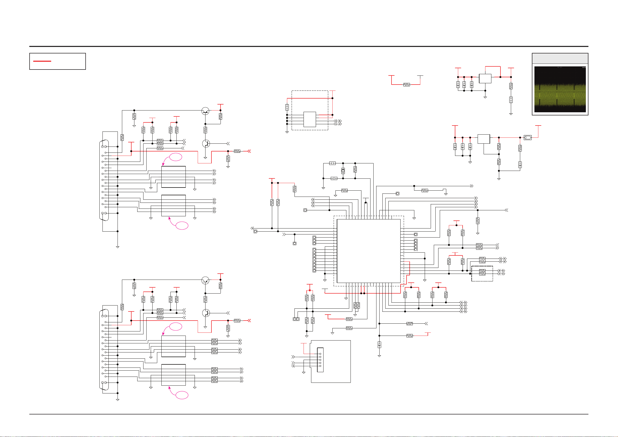
Schematic Diagram
1. D2+
2. D2 SHILD
3. D2-
4. D1+
5. D1 SHIELD
7. D0+
6. D1-
8. D0 SHIELD
9. DO-
11. CK SHIELD
10. CK+
13. CE REMOTE
14. NC
18. +5V
19. HPDET
17. GND
16.DDC DATA
15. DDC CLK
12. CK-
PORT1
16.DDC DATA
15. DDC CLK
9. DO-
5. D1 SHIELD
3. D2-
1. D2+
7. D0+
4. D1+
11. CK SHIELD
10. CK+
6. D1-
12. CK-
14. NC
2. D2 SHILD
13. CE REMOTE
8. D0 SHIELD
17. GND
19. HPDET
18. +5V
PORT0
HT1
HT3
HT0
PR NC
NC
ADJ
P1_5V
P1_5V D5.0V_PW
P1_5V
P0_5V
P0_5V
D5.0V_PW
P0_5V
D5.0V_PW
M3.3V
D5.0V_PW
D5.0V_PW
M3.3V
M3.3VM3.3V
M3.3V
M3.3V
1.8VD3.3V
AL5V_PW CE3.3V
M3.3V
D3.3V
4C5>
P1_PWR5V
P0_PWR5V
4C5>
RX21P
RX21M
RX01M
RX11P
RX11M
RX01P
HT1_CTLB
RXC1M
RXC1P
RX10M
RX10P
RX20P
RXO0P
RXO0M
RXC0P
RXC0M
RX20M
I2C_INT
EP94A2_INTB
HT0_CTLB
EPF021A_P70
EPF021A_OP0
EPF021A_P71
F_RESET
P1_PWR5V
P3_PWR5V
P0_PWR5V
MCU_SDA
HT0_CTLB
HT1_CTLB
EPF021A_OP0
EDID_CLK
EP94A2_RSTB
HT3_CTLB
HPD1
I2C_HDMI_CLK
I2C_HDMI_DATA
H_W_CLK
H_W_DATA
EE_SDA
FD05015-19
CN402
1
10
11
12
13
14
15
16
17
18
19
2
3
4
5
6
7
8
9
MGND1
MGND2
MGND3
MGND4
DGND
DGND
RCLAMP0524P.TCT
D404
1 10
2
3
4
5 6
7
8
9
DGND
RCLAMP0524P.TCT
D403
1 10
2
3
4
5 6
7
8
9
1KOHM
1/16W
R402
47KOHM
1/16W
R404
DGND
56KOHM
1/16W
RE73
0OHM
1/16W
R412
1/16W
0OHM
R411
1/16W
10KOHM
R406
1/16W
0OHM
R410
NC
R414NCR424
FD05015-19
CN401
1
10
11
12
13
14
15
16
17
18
19
2
3
4
5
6
7
8
9
MGND1
MGND2
MGND3
MGND4
DGND
DGND
RCLAMP0524P.TCT
D402
1 10
2
3
4
5 6
7
8
9
DGND
RCLAMP0524P.TCT
D401
1 10
2
3
4
5 6
7
8
9
DGND
DGND
10OHM
R498
10OHM
R497
5D5<
5D5<
10OHM
R496
10OHM
R495
10OHM
R494
10OHM
R493
10OHM
R492
5D5<
5D5<
5D5<
5D5<
RXSCL1
3F1<>
HDMI_CEC
6E8<
4B3<
DGND
DTC124EK
Q404
5A4<>
RXSDA1
330OHM
1/16W
R426
2SA1979S-Y
Q402
10OHM
R491
DGND
NC
R430
5D5<
5D5<
4C7>
1/16W
1KOHM
R432
1/16W
10KOHM
R428
4D8<
4D8>
4C7>
TP421
TP422
DGND
DGND
5D4<
5D5<
5D4<
5D4<
5D4<
5D4<
5D4<
5D4<
DGND
NC
R429
14E8<
TP425
TP434
10KOHM
1/16W
R463
1/16W
10KOHM
R464
NC
R415
DGND
1KOHM
1/16W
R401
1/16W
47KOHM
R403
DGND
56KOHM
1/16W
RE71
0OHM
1/16W
R409
1/16W
0OHM
R408
0OHM
1/16W
R407
1/16W
10KOHM
R405
NC
R413NCR423
RXSCL0
4E3<
6E8<
3F1<>
HDMI_CEC
RXSDA0
5C2<> DTC124EK
Q403
1/16W
330OHM
R425
2SA1979S-Y
Q401
4C7>
1/16W
1KOHM
R431
1/16W
10KOHM
R427
DGND
16V
100NF
C401
DGND
A2008WVO-5P
CF401
1
2
3
4
5
DGND
1/16W
10KOHM
R7391
1/16W
10KOHM
R7392
DGND
NC
R434
NC
R436
M3.3V
10KOHM
1/16W
R458
3.3KOHM 1/16W
R451
DGND
DGND
10KOHM
1/16W
HR2
10KOHM
1/16W
HR3
DGND
10UF
10V
C2203
NC
R461
1
2
0OHM
R456
14D2>7B4<14H5>
10KOHM
1/16W
R433
10KOHM
1/16W
R435
TP424
TP414
TP415
TP417
TP416
TP401
TP407
TP408
DGND
TP405
TP404
TP403
TP406
4B4<
4E4<
5F3<
DGND
50V
15PF
C403
15PF
50V
C402
DGND
1/16W
10KOHM
HR1
24MHZ
X401
10MOHM
1/10W
R453
DGND
TP418
TP430
TP419
TP429
TP428
M3.3V
TP427
DGND
1/16W
10KOHM
R465
NC
R447NCR448
5C2<>
6D4>
EDID_DATA
14E4<
5C2<>
MCU_SCL
6D4> 14D8<
10KOHM
1/16W
R441
NC
R444
1/16W
10KOHM
R443
NC
RU8
NC
RU7
0OHM1/16W
RU6
0OHM1/16W
RU5
NC
R442
1/16W
0OHM
R437
0OHM
1/16W
R438
DGND
47KOHM
1/16W
R416
DGND
5E3<
5A3>
4B3<
4E3<
4F4<
DGND
14D3<>
14A5>
15E11>
14B4<>
15E9>14B4<>
EPF021A_P70
4F4>
4F4<
EPF021A_P71
3F1> 6E8> 14H6<>
DGND
1/10W
120OHM
R467
6.3V
22UF
C414
AT24C08AN-10SU-2.7
IC401
1
2
3
4 5
6
7
8
5C2<>
EE_SCL
5C2<>
1/10W
0OHM
R2304
D3.3V
100NF
16V
C405
10V10UF
C408
10UF
10V
C410
AIC1117ACE
IC405
1
2
3
DGND
100NF 16V
C406
10V10UF
C407
10V
10UF
C409
NCP1117ST33T3G
IC404
1
2
3
MGND1
270OHM
1/10W
R466
DGND
22UF
6.3V
C412
1OHM
1/10W
R2306
0.01OHM
5000MA
BD4110
1/10W
1OHM
R469
IC402
1
10111213141516
17
18
19
2
20
21
22
23
24
25
26
27
28
29
3
30
31
32
33
34
35
36
37
38
39
4
40
41
42
43
44
45
46
47
48
49
5
50
51
52
53
54
55
56
57
58
59
6
60
61
62
63
64
7
8
9
ADC[2]
ADC[3]
PWM[0]
PWM[1]
TIM[0]
TIM[1]
VSS
X2_OUT
X2_IN
RESERVED
P3[0]
P3[1]
P3[2]
P3[3]
P3[4]
P1[3]
P1[4]
P1[5]
P1[6]
P1[7]
EXT_INT
VDD
VDD
X1_OUT
X1_IN
OP_MODE[0]
OP_MODE[1]
P2[0]
P2[1]
P3[5]
P0[1]
VSSA
P0[0]
VREFL
P1[2]
P1[1]
P1[0]
P2[2]
P2[3]
P2[4]
P2[5]
P2[6]
P2[7] SPI_CLK
SPI_DO
SPI_DI
VSS
P0[7]
P0[6]
P0[5]
P0[4]
P0[3]
P0[2]
P3[6]
P3[7]
RSTB
ID
DM
DP
VBUS
VDDA
VREFH
ADC[0]
ADC[1]
OUT_LINES
GND
OUT_LINESIN_LINES
GND
IN_LINES
IN_LINES
IN_LINES OUT_LINES
OUT_LINES
OUT_LINES
GND
OUT_LINESIN_LINES
GND
IN_LINES
IN_LINES
IN_LINES OUT_LINES
OUT_LINES
OUT_LINES
GND
OUT_LINESIN_LINES
GND
IN_LINES
IN_LINES
IN_LINES OUT_LINES
OUT_LINES
OUT_LINES
GND
OUT_LINESIN_LINES
GND
IN_LINES
IN_LINES
IN_LINES OUT_LINES
OUT_LINES
E
B
C
EBC
E
B
C
EBC
SDAVSS
WP
VCC
SCLA2
A1
A0
GND
OUTIN
OUT
GND
OUTIN
1. D2+
2. D2 SHILD
3. D2-
4. D1+
5. D1 SHIELD
7. D0+
6. D1-
8. D0 SHIELD
9. DO-
11. CK SHIELD
10. CK+
13. CE REMOTE
14. NC
18. +5V
19. HPDET
17. GND
16.DDC DATA
15. DDC CLK
12. CK-
PORT1
16.DDC DATA
15. DDC CLK
9. DO-
5. D1 SHIELD
3. D2-
1. D2+
7. D0+
4. D1+
11. CK SHIELD
10. CK+
6. D1-
12. CK-
14. NC
2. D2 SHILD
13. CE REMOTE
8. D0 SHIELD
17. GND
19. HPDET
18. +5V
PORT0
HT1
HT3
HT0
PR NC
NC
ADJ
P1_5V
P1_5V D5.0V_PW
P1_5V
P0_5V
P0_5V
D5.0V_PW
P0_5V
D5.0V_PW
M3.3V
D5.0V_PW
D5.0V_PW
M3.3V
M3.3VM3.3V
M3.3V
M3.3V
1.8VD3.3V
AL5V_PW CE3.3V
M3.3V
D3.3V
FD05015-19
DGND
DGND
RCLAMP0524P.TCT
DGND
RCLAMP0524P.TCT
1KOHM
1/16W
47KOHM
1/16W
DGND
56KOHM
1/16W
0OHM
1/16W
1/16W
0OHM
1/16W
10KOHM
1/16W
0OHM
NC
NC
FD05015-19
DGND
DGND
RCLAMP0524P.TCT
DGND
RCLAMP0524P.TCT
DGND
DGND
10OHM
10OHM
10OHM
10OHM
10OHM
10OHM
10OHM
DGND
DTC124EK
330OHM
1/16W
2SA1979S-Y
10OHM
DGND
NC
1/16W
1KOHM
1/16W
10KOHM
DGND
DGND
DGND
NC
10KOHM
1/16W
1/16W
10KOHM
NC
DGND
1KOHM
1/16W
1/16W
47KOHM
DGND
56KOHM
1/16W
0OHM
1/16W
1/16W
0OHM
0OHM
1/16W
1/16W
10KOHM
NC
NC
DTC124EK
1/16W
330OHM
2SA1979S-Y
1/16W
1KOHM
1/16W
10KOHM
DGND
16V
100NF
DGND
A2008WVO-5P
DGND
1/16W
10KOHM
1/16W
10KOHM
DGND
NC
NC
M3.3V
10KOHM
1/16W
3.3KOHM 1/16W
DGND
DGND
10KOHM
1/16W
10KOHM
1/16W
DGND
10UF
10V
NC
0OHM
10KOHM
1/16W
10KOHM
1/16W
DGND
DGND
50V
15PF
15PF
50V
DGND
1/16W
10KOHM
24MHZ
10MOHM
1/10W
DGND
M3.3V
DGND
1/16W
10KOHM
NC
NC
10KOHM
1/16W
NC
1/16W
10KOHM
NC
NC
0OHM 1/16W
0OHM 1/16W
NC
1/16W
0OHM
0OHM
1/16W
DGND
47KOHM
1/16W
DGND
DGND
DGND
1/10W
120OHM
6.3V
22UF
AT24C08AN-10SU-2.7
1/10W
0OHM
D3.3V
100NF
16V
10V10UF
10UF
10V
AIC1117ACE
DGND
100NF 16V
F
U
01 V01
10V
10UF
270OHM
1/10W
DGND
22UF
6.3V
1OHM
1/10W
0.01OHM
5000MA
1/10W
1OHM
CN402
D404
D403
R402
R404
RE73
R412
R411
R406
R410
R414
R424
CN401
D402
D401
R498
R497
R496
R495
R494
R493
R492
Q404
R426
Q402
R491
R430
R432
R428
TP421
TP422
R429
TP425
TP434
R463
R464
R415
R401
R403
RE71
R409
R408
R407
R405
R413
R423
Q403
R425
Q401
R431
R427
C401
CF401
R7391
R7392
R434
R436
R458
R451
HR2
HR3
C2203
R461
R456
R433
R435
TP424
TP414
TP415
TP417
TP416
TP401
TP407
TP408
TP405
TP404
TP403
TP406
C403
C402
HR1
X401
R453
TP418
TP430
TP419
TP429
TP428
TP427
R465
R447
R448
R441
R444
R443
RU8
RU7
RU6
RU5
R442
R437
R438
R416
R467
C414
IC401
R2304
C405
C408
C410
IC405
C406
C407
C409
IC404
R466
C412
R2306
BD4110
R469
IC402
4C5>
4C5>
5D5<
5D5<
5D5<
5D5<
5D5<
5D5<
3F1<>
6E8<
4B3<
5A4<>
5D5<
5D5<
4C7>
4D8<
4D8>
4C7>
5D4<
5D5<
5D4<
5D4<
5D4<
5D4<
5D4<
5D4<
14E8<
4E3<
6E8<
3F1<>
5C2<>
4C7>
14D2>>5H41 <4B7
4B4<
4E4<
5F3<
5C2<>
6D4> 14E4<
5C2<>
6D4> 14D8<
5E3<
5A3>
4B3<
4E3<
4F4<
14D3<>
14A5>
15E11>
14B4<>
15E9>14B4<>
4F4>
4F4<
3F1> 6E8> 14H6<>
5C2<>
5C2<>
P1_PWR5V
P0_PWR5V
RX21P
RX21M
RX01M
RX11P
RX11M
RX01P
HT1_CTLB
RXC1M
RXC1P
RX10M
RX10P
RX20P
RXO0P
RXO0M
RXC0P
RXC0M
RX20M
I2C_INT
EP94A2_INTB
HT0_CTLB
EPF021A_P70
EPF021A_OP0
EPF021A_P71
F_RESET
P1_PWR5V
P3_PWR5V
P0_PWR5V
MCU_SDA
HT0_CTLB
HT1_CTLB
EPF021A_OP0
EDID_CLK
EP94A2_RSTB
HT3_CTLB
HPD1
I2C_HDMI_CLK
I2C_HDMI_DATA
H_W_CLK
H_W_DATA
EE_SDA
RXSCL1
HDMI_CEC
RXSDA1
RXSCL0
HDMI_CEC
RXSDA0
EDID_DATA
MCU_SCL
EPF021A_P70
EPF021A_P71
EE_SCL
1
10
11
12
13
14
15
16
17
18
19
2
3
4
5
6
7
8
9
MGND1
MGND2
MGND3
MGND4
1 10
2
3
4
5 6
7
8
9
1 10
2
3
4
5 6
7
8
9
1
10
11
12
13
14
15
16
17
18
19
2
3
4
5
6
7
8
9
MGND1
MGND2
MGND3
MGND4
1 10
2
3
4
5 6
7
8
9
1 10
2
3
4
5 6
7
8
9
1
2
3
4
5
1
2
1
2
3
4 5
6
7
8
1
2
3
1
2
3
MGND1
1
10
11
12
13
14
15
16
17
18
19
2
20
21
22
23
24
25
26
27
28
29
3
30
31
32
33
34
35
36
37
38
39
4
40
41
42
43
44
45
46
47
48
49
5
50
51
52
53
54
55
56
57
58
59
6
60
61
62
63
64
7
8
9
ADC[2]
ADC[3]
PWM[0]
PWM[1]
TIM[0]
TIM[1]
VSS
X2_OUT
X2_IN
RESERVED
P3[0]
P3[1]
P3[2]
P3[3]
P3[4]
P1[3]
P1[4]
P1[5]
P1[6]
P1[7]
EXT_INT
VDD
VDD
X1_OUT
X1_IN
OP_MODE[0]
OP_MODE[1]
P2[0]
P2[1]
P3[5]
P0[1]
VSSA
P0[0]
VREFL
P1[2]
P1[1]
P1[0]
P2[2]
P2[3]
P2[4]
P2[5]
P2[6]
P2[7] SPI_CLK
SPI_DO
SPI_DI
VSS
P0[7]
P0[6]
P0[5]
P0[4]
P0[3]
P0[2]
P3[6]
P3[7]
RSTB
ID
DM
DP
VBUS
VDDA
VREFH
ADC[0]
ADC[1]
OUT_LINES
GND
OUT_LINESIN_LINES
GND
IN_LINES
IN_LINES
IN_LINES OUT_LINES
OUT_LINES
OUT_LINES
GND
OUT_LINESIN_LINES
GND
IN_LINES
IN_LINES
IN_LINES OUT_LINES
OUT_LINES
OUT_LINES
GND
OUT_LINESIN_LINES
GND
IN_LINES
IN_LINES
IN_LINES OUT_LINES
OUT_LINES
OUT_LINES
GND
OUT_LINESIN_LINES
GND
IN_LINES
IN_LINES
IN_LINES OUT_LINES
OUT_LINES
E
B
C
EBC
E
B
C
EBC
SDAVSS
WP
VCC
SCLA2
A1
A0
GND
OUTIN
OUT
GND
OUTIN
7-10 HDMI MICOM
POWER
TP2
TP2
TP2
TP2
This Document can not be used without Samsung’s authorization.
7-10 Samsung Electronics
TP2
 Loading...