

Samsung HT-BD1255 Schematic
5.1CH Blu-ray
Home Theater System
Model Name : HT-BD1255
Model Code : HT-BD1255T/XAC
Speaker PS-BD1255
Front PS-FBD1255
Center PS-CBD1255
Rear PS-RBD1255
Subwoofer PS-WBD1255
SERVICE
Manual
5.1CH Blu-ray Home Theater System
HT-BD1255
CONTENTS
1. Precaution
2. Product Specification
3. Disassembly & Reassembly
4. Troubleshooting
5. Exploded View & Part List
6. PCB Diagram
7. Schematic Diagram
Refer to the service manual in the GSPN (see the rear cover) for the more information.
GSPN (Global Service Partner Network)
Area Web Site
North America service.samsungportal.com
Latin America latin.samsungportal.com
CIS cis.samsungportal.com
Europe europe.samsungportal.com
China china.samsungportal.com
Asia asia.samsungportal.com
Mideast & Africa mea.samsungportal.com
This Service Manual is a property of Samsung Electronics
Co.,Ltd. Any unauthorized use of Manual can be punished
under applicable International and/or domestic law.
Samsung Electronics Co.,Ltd. Apr. 2009
©
Printed in Korea

Contents
1. Precaution
1-1 Safety Precautions ...........................................................................................1-1
1-2 Servicing Precautions ......................................................................................1-3
Precautions for Electrostatically Sensitive Devices (ESDs) .............................1-4
1-3
2. Product Specification
2-1 Product Feature ...............................................................................................2-1
2-2 Specifications ...................................................................................................2-2
Specifications Analysis .....................................................................................2-8
2-3
Accessories ......................................................................................................2-10
2-4
3. Disassembly & Reassembly
3-1 Overall Disassembly & Reassembly ................................................................3-1
3-2 DECK Disassembly & Reassembly..................................................................3-4
4. Troubleshooting
4-1 Checkpoints by Error Mode..............................................................................4-2
4-2 Initialization & Upgrade Methods .....................................................................4-34
Buyer-Region Code Setting Method ................................................................4-38
4-3
5. Exploded View & Part List
5-1 Product Exploded View ....................................................................................5-2
5-2 DECK Exploded View ......................................................................................5-4
Speaker System ...............................................................................................5-6
5-3
Electrical Part List ............................................................................................5-7
5-4

Contents
6. PCB Diagram
6-1 Wiring Diagram ................................................................................................6-2
6-2 FRONT PCB Top ..............................................................................................6-3
FRONT PCB Bottom ........................................................................................6-5
6-3
KEY PCB Top ...................................................................................................6-6
6-4
KEY PCB Bottom .............................................................................................6-8
6-5
AMP PCB Top ..................................................................................................6-9
6-6
AMP PCB Bottom .............................................................................................6-11
6-7
MAIN PCB Top .................................................................................................6-13
6-8
MAIN PCB Bottom ...........................................................................................6-16
6-9
SMPS PCB Top ................................................................................................6-18
6-10
1 SMPS PCB Bottom ..........................................................................................6-19
6-1
7. Schematic Diagram
7-1 Overall Block Diagram .....................................................................................7-2
7-2 FRONT .............................................................................................................7-3
KEY ..................................................................................................................7-4
7-3
AMP .................................................................................................................7-5
7-4
AUDIO / VIDEO (COMPONENT, COMPOSITE) ..............................................7-6
7-5
HDMI CEC / TX (SIL9134) ...............................................................................7-7
7-6
Boot Strap Option.............................................................................................7-8
7-7
EBI ADDR, EBI DATA .......................................................................................7-9
7-8
CLOCK, BBS....................................................................................................7-10
7-9
BCM7440 POWER...........................................................................................7-11
7-10
1 DDR2 BANK0, BANK1 .....................................................................................7-12
7-1
SYSTEM MICOM / TUNER / SRC / WIRELESS .............................................7-13
7-12
EXTERNAL IN & AUDIO FLOW .......................................................................7-14
7-13
Ethernet, S-ATA, USB ......................................................................................7-15
7-14
GPIO / IPOD / BT .............................................................................................7-16
7-15
NAND, FlexOneNand .......................................................................................7-17
7-16
MAIN POWER..................................................................................................7-18
7-17
DSP SDRAM / FLASH .....................................................................................7-19
7-18
BCM7620 (F/E) ................................................................................................7-20
7-19
SMPS (110V) ...................................................................................................7-21
7-20
SMPS (220V) ...................................................................................................7-22
7-21

2. Product Specification
2-1 Product Feature
New features for both HT-BD1250
- BD-LIVE from the beginning of the Mass Production
- DTS-HD Master Audio decoding from the beginning of the Mass Production
- Wireless Network
• Bundle ‘Wireless LAN adapter’ not included for HT-BD1250
- MP3, JPG
- 2 USB port (Not only on rear, but also on front)
- I-POD Docking (Only USA)
- Various Video Setups
• Progressive Mode
• Still Mode
• BD Wise
• Picture Control
Product Specification
HT-BD2→HT-BD1250
- DivX (Only EU)
- PC Connected
- USB HOST
- Profile 2.0 Ready
- Netflix, Pandora
- I-POD Docking (Only USA)
- Wireless Rear Speaker
Samsung Electronics 2-1

Product Specification
2-2 Specifications
2-2-1
HT-BD1250/HT-BD1252/HT-BD1255Specications
Basic Specification
Power Consumption 85 W
Weight 4.4 Kg
GENERAL
DISC
Dimensions 440 (W) x 345 (D) x 63 (H) mm
Operating Temperature Range +5°C ~ +35°C
Operating
BD
(Blu-ray Disc) Reading Speed: 4.917m/sec
DVD
(Digital Versatile Disc)
12 cm
CD:
(COMPACT DISC)
8 cm
CD:
(COMPACT DISC)
Humidity Range 10% to 75%
Reading Speed: 3.49 ~ 4.06 m/sec.
Approx. Play Time (Single Sided, Single Layer Disc):
135 min.
Reading Speed: 4.8 ~ 5.6 m/sec.
Maximum Play Time: 74 min.
Reading Speed: 4.8 ~ 5.6 m/sec.
Maximum Play Time: 20 min.
VIDEO
OUTPUT
VIDEO/
AUDIO
AMPLIFIER
1 channel: 1.0 Vp-p (75Ω load)
Composite
Component
HDMI
Front
Center
Surround
Subwoofer
Frequency
Video
Video
speaker output 165W x 2 (3Ω)
speaker output 170W (3Ω)
speaker output 165W x 2 (3Ω)
speaker output 170W (3Ω)
range
Blu-ray Disc: 576i (480i)
DVD: 576i (480i)
Y: 1.0 Vp-p (75Ω load)
Pr: 0.70 Vp-p (75Ω load)
Pb: 0.70 Vp-p (75Ω load)
Blu-ray Disc: 1080i, 720p, 576p (480p), 576i (480i)
DVD: 576p (480p), 480i
1080p, 1080i, 720p, 576p (480p)
PCM multi channel audio, Bit stream audio, PCM audio
Analog input: 20Hz ~ 20kHz (±3dB)
Digital input: 20Hz ~ 44kHz (±3dB)
Ratio 70dB
S/N
Channel
Input
2-2 Samsung Electronics
separation 60dB
sensitivity (AUX) 500mV
HT-BD1250 Speaker Specification
Product Specification
Speaker system
Impedance
Frequency range
Output sound pressure level
SPEAKER
Rated input
Maximum input
Dimensions (W x H x D)
Weights
HT-BD1252 Speaker Specification
Speaker system
5.1ch Speaker System
Front Surround Center Subwoofer
3Ω 3Ω 3Ω 3Ω
140Hz ~
50KHz
87dB/W/M 87dB/W/M 87dB/W/M 90dB/W/M
165W 165W 170W 170W
330W 330W 340W 340W
Front/Surround: 100.5 x 210 x 99 mm
Centre: 300 x 59 x 50 mm
Subwoofer: 201 x 403 x 410 mm
Front/Surround: 0.70 Kg, Centre: 0.33 Kg
Subwoofer: 5.39 Kg
Front Surround Center Subwoofer
140Hz ~
20KHz
5.1ch Speaker System
140Hz ~
20KHz
40Hz ~
160Hz
SPEAKER
Impedance
Frequency range
Output sound pressure level
Rated input
Maximum input
Dimensions (W x H x D)
Weights
3Ω 3Ω 3Ω 3Ω
140Hz ~
20KHz
87dB/W/M 87dB/W/M 87dB/W/M 88dB/W/M
165W 165W 170W 170W
330W 330W 340W 340W
Front : 260 x 1120x 260 mm
Surround : 100 x 151 x 89 mm
Centre : 300 x 59 x 50 mm
Subwoofer : 201 x 403 x 410 mm
Front: 2.18 Kg, Surround: 0.42 Kg
Centre: 0.32 Kg, Subwoofer: 5.39 Kg
140Hz ~
20KHz
140Hz ~
20KHz
40Hz ~
160Hz
Samsung Electronics 2-3
Product Specification
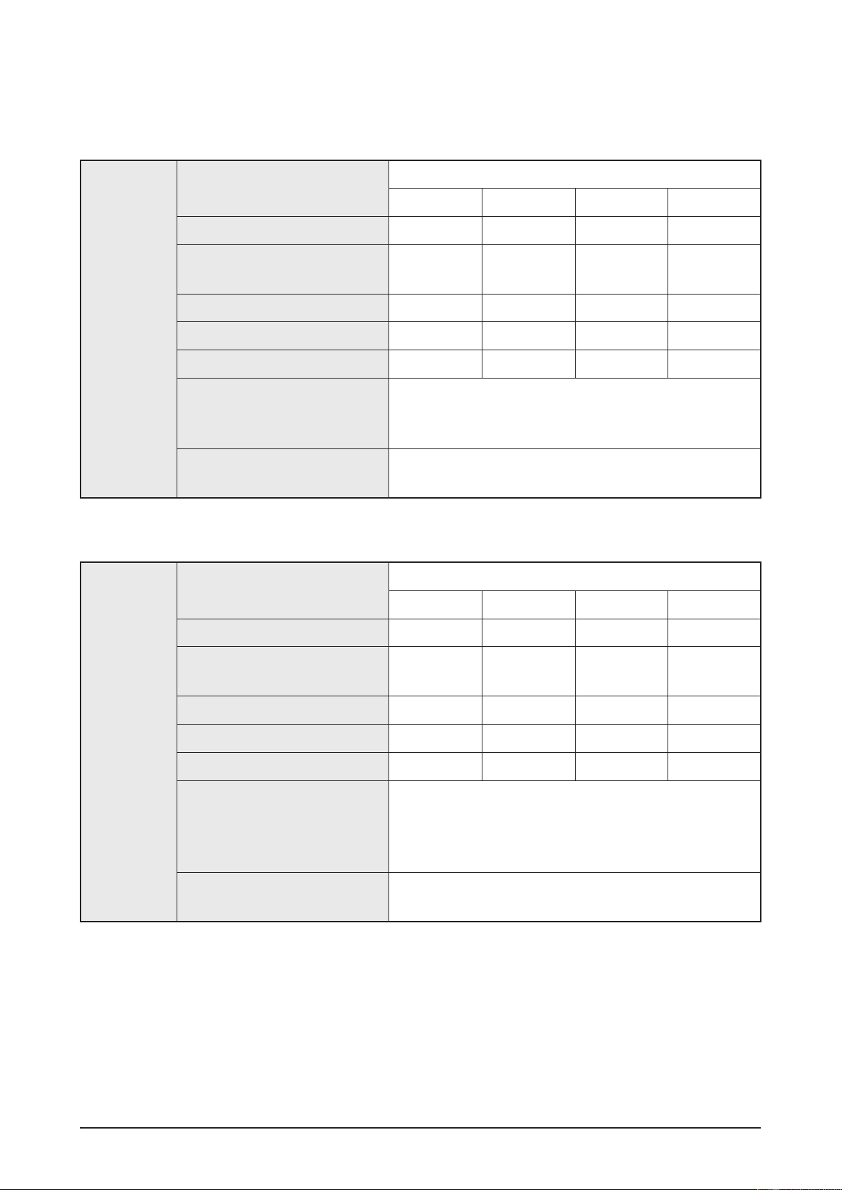
HT-BD1255 Speaker Specification
SPEAKER
Speaker system
Impedance
Frequency range
Output sound pressure level
Rated input
Maximum input
Dimensions (W x H x D)
Weights
5.1ch Speaker System
Front Surround Center Subwoofer
3Ω 3Ω 3Ω 3Ω
140Hz ~
50KHz
140Hz ~
20KHz
140Hz ~
20KHz
40Hz ~
160Hz
87dB/W/M 87dB/W/M 87dB/W/M 88dB/W/M
165W 165W 170W 170W
330W 330W 340W 340W
Front/Surround: 260 x 1202 x 260 mm
Centre: 300 x 59 x 50 mm
Subwoofer: 201 x 403 x 410 mm
Front/Surround: 2.88 Kg,
Centre: 0.34 Kg, Subwoofer: 5.39 Kg
2-4 Samsung Electronics

Product Specification
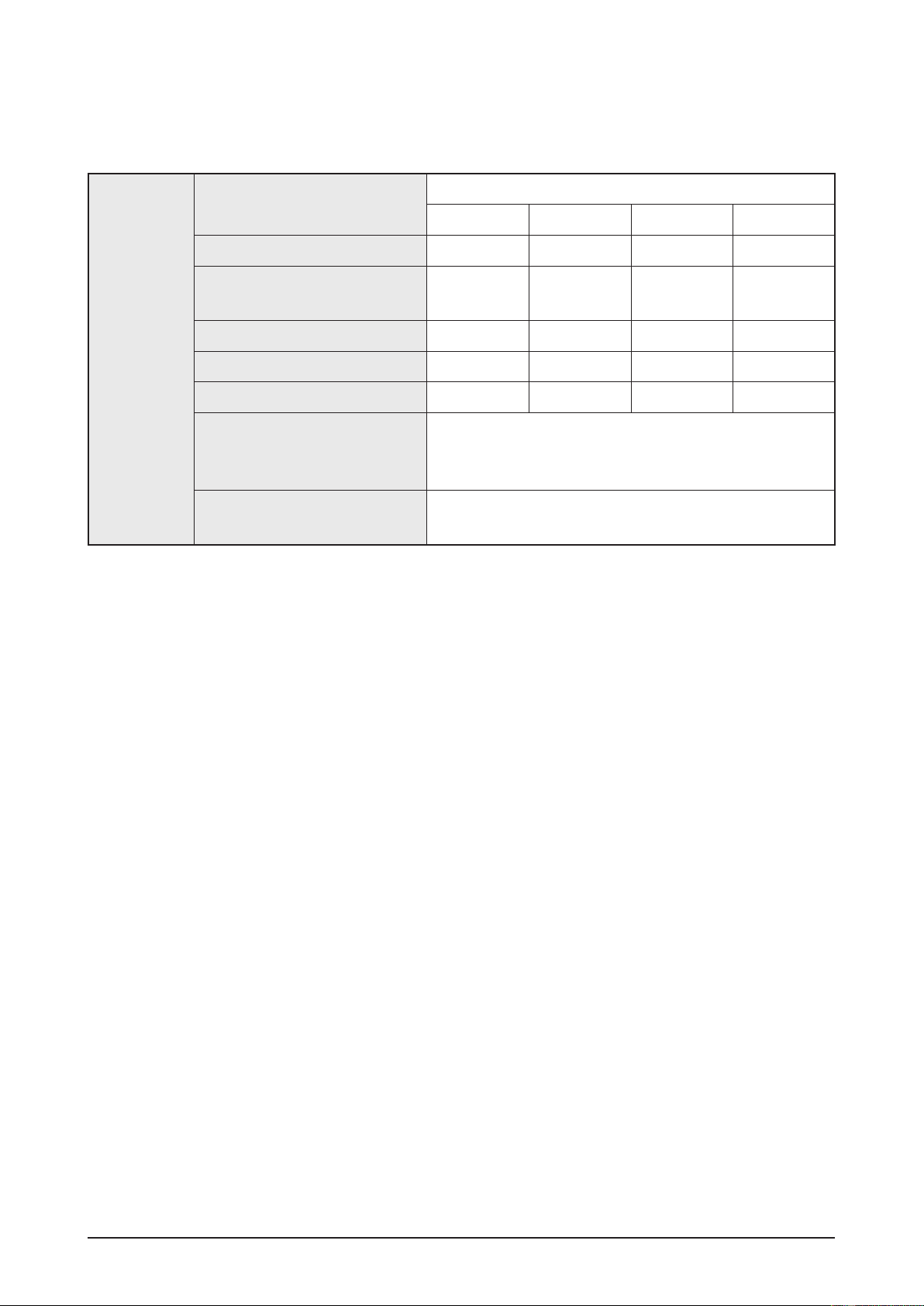
2-2-2
HT-BD1220Specications
Basic Specification
Power Consumption 85 W
Weight 4.4 Kg
GENERAL
TUNER
FM
DISC
Dimensions 440 (W) x 345 (D) x 63 (H) mm
Operating Temperature Range +5°C ~ +35°C
Operating
FM Frequency Range 87.5 ~ 108.0 MHz
/ noise ratio 60 dB
Signal
Usable
T
BD
DVD
CD:
(COMPACT DISC)
sensitivity 10 dB
otal harmonic distortion 1 %
(Blu-ray Disc) Reading Speed: 4.917m/sec
(Digital Versatile Disc)
12 cm
Humidity Range 10% to 75%
Reading Speed: 3.49 ~ 4.06 m/sec.
Approx. Play Time (Single Sided, Single Layer Disc):
135 min.
Reading Speed: 4.8 ~ 5.6 m/sec.
Maximum Play Time: 74 min.
VIDEO
OUTPUT
VIDEO/
AUDIO
AMPLIFIER
8 cm
CD:
(COMPACT DISC)
Composite
Component
HDMI
Front
Center
Frequency
Video
Video
speaker output 165W x 2 (3Ω)
speaker output 170W (3Ω)
range
Reading Speed: 4.8 ~ 5.6 m/sec.
Maximum Play Time: 20 min.
1 channel: 1.0 Vp-p (75Ω load)
Blu-ray Disc: 576i/480i
DVD: 576i/480i
Y: 1.0 Vp-p (75Ω load)
Pr: 0.70 Vp-p (75Ω load)
Pb: 0.70 Vp-p (75Ω load)
Blu-ray Disc: 1080i, 720p, 576p/480p, 576i/480i
DVD: 576p/480p, 576i/480i
1080p, 1080i, 720p, 576p/480p
PCM multi channel audio, Bit stream audio, PCM audio
Analog input: 20Hz ~ 20kHz (±3dB)
Digital input: 20Hz ~ 44kHz (±3dB)
Ratio 70dB
S/N
Channel
Input
Samsung Electronics 2-5
separation 60dB
sensitivity (AUX) 500mV
Product Specification
HT-BD1220 Speaker Specification
SPEAKER
Speaker system
Impedance
Frequency range
Output sound pressure level
Rated input
Maximum input
Dimensions (W x H x D)
Weights
2.1ch Speaker System
Front Subwoofer
3Ω 3Ω
140Hz ~ 50KHz 40Hz ~ 160Hz
87dB/W/M 90dB/W/M
165W 170W
330W 340W
Front: 100.5 x 210 x 99 mm
Subwoofer: 201 x 403 x 410 mm
Front: 0.70 Kg
Subwoofer: 5.39 Kg
2-6 Samsung Electronics
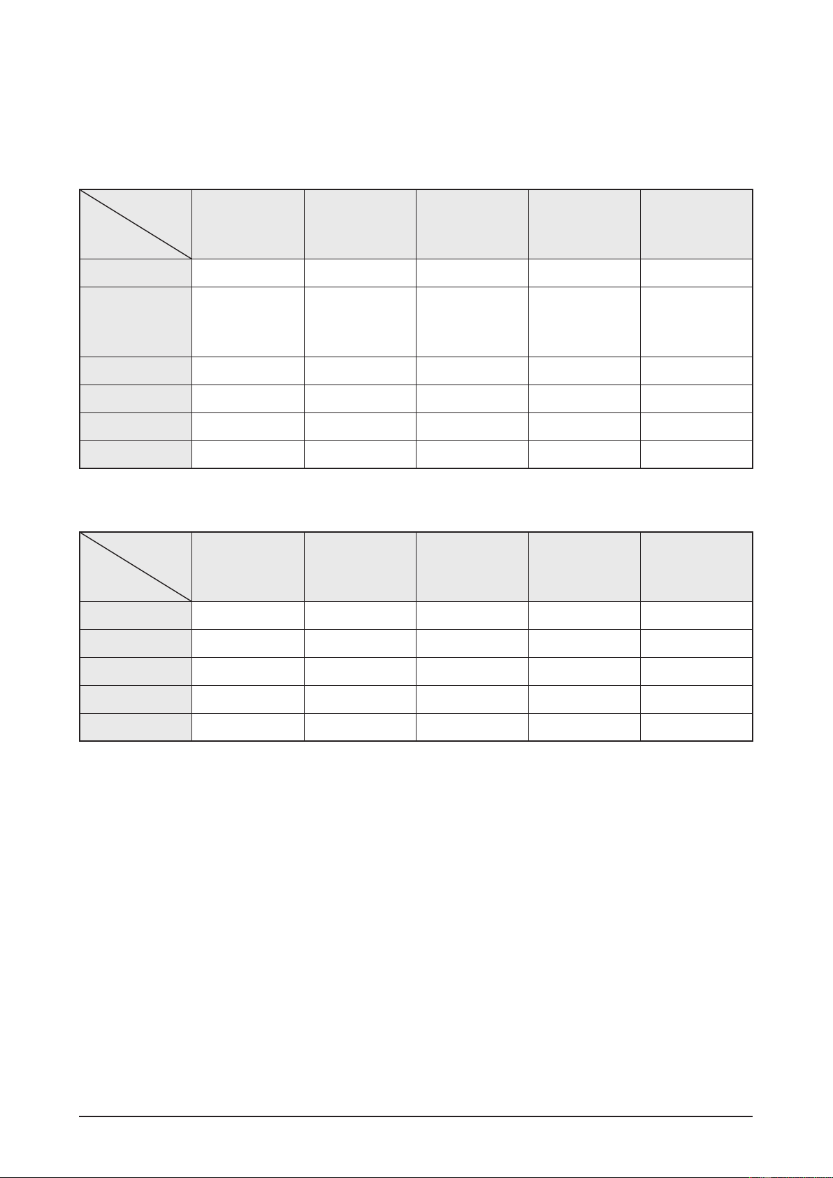
2-2-3 Video Output SPEC
BD playback
Product Specification
Output
Setup
1080P@60F 1080P@60F 480i 1080i 480i
1080P@24F 1080P@24F 480i 1080i 480i
1080i 1080i 1080i 1080i 480i
720P 720P 720P 720P 480i
480P 480P 480P 480P 480i
480i 480P 480i 480i 480i
HDMI Output
Component
[HDMI
Connected]
Component
[HDMI not
Connected]
CVBS Output Remark
DVD playback
Setup
Output
HDMI Output
Component
[HDMI
Connected]
Component
[HDMI not
Connected]
CVBS Output Remark
Only when
source is
1080P@24F
1080P@60F 1080P@60F 480i 480P 480i
1080i 1080i 480i 480P 480i
720P 720P 480i 480P 480i
480P 480P 480i 480P 480i
480i 480P 480i 480i 480i
Samsung Electronics 2-7
Product Specification
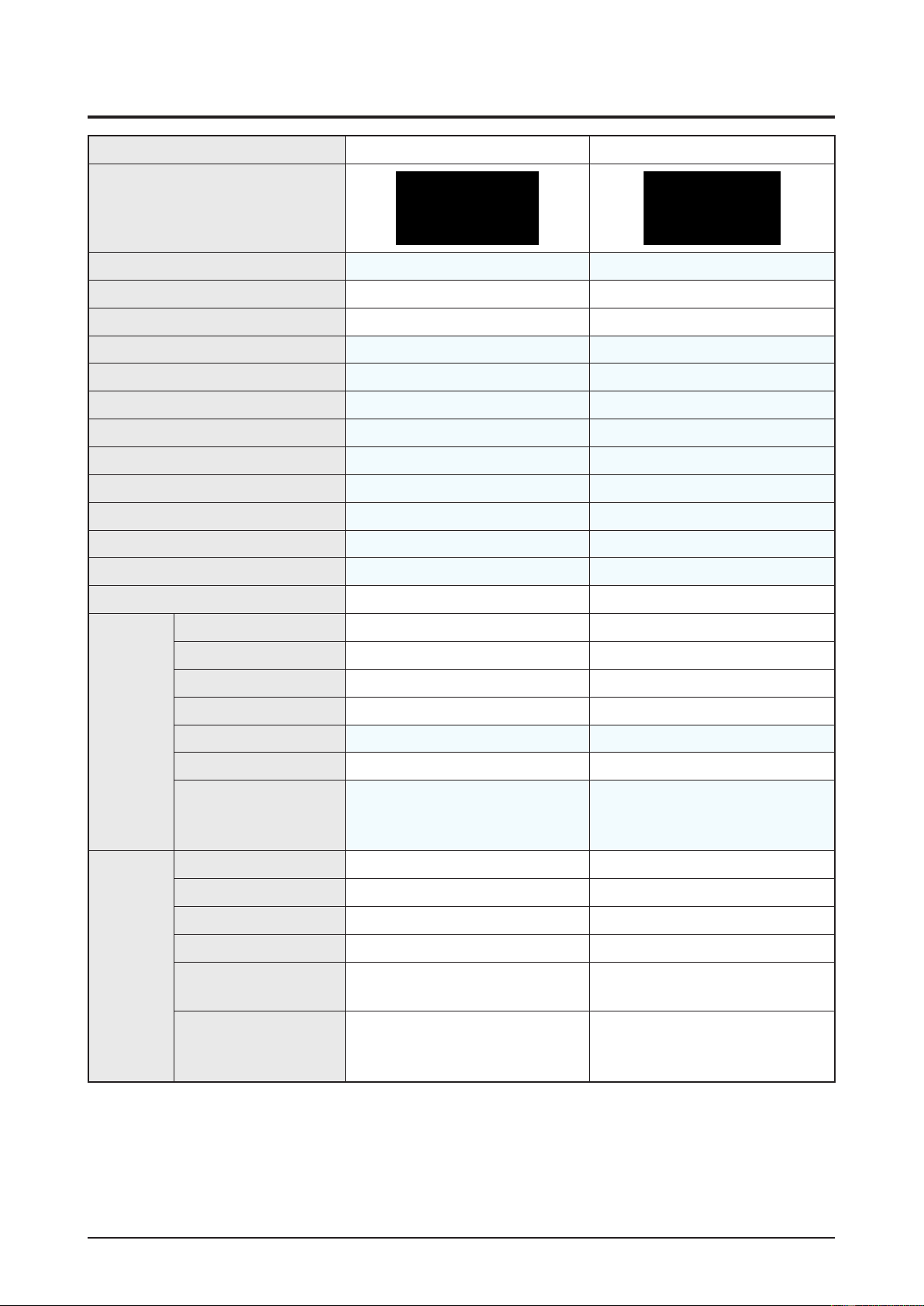
2-3 Specifications Analysis
Model Name HT-BD1250 HT-BD2
Photo
Profile Blu-ray 2.0 from the beginning Blu-ray 1.0
HDMI
DVD, CD
JPG
MP3,
HOST
USB
I-POD (only USA) X
ireless LAN
W
(SD) (only EU) X
DivX
ireless Rear
W
Memory
BD-RE
Update
Required
Slot X (External USB support) X
support Support 1.0 Does not support 1.0
Method CD, Network, USB CD, Network
time for update 3~4min 10~12 min
Remote long long
HDMI 1.3 1.3
24frame
1080p
(Anynet+)
CEC
Color X (8bit) X (8bit)
Deep
xvYCC
X
X
X
X
Video
Audio Transmission
HD
Quality control
Picture
V
ideo Processor Main SOC Internal Scaler Main SOC Internal Scaler
1080p
60frame
60frame
1080i
24frame
1080p
video output for
480i/p
Blu-ray
Simultaneous
Output between HDMI/
Component/CVBS
Video
(Progressive Mode, Still Mode,
BD Wise, Picture Control)
X
: application, X: non-application
2-8 Samsung Electronics
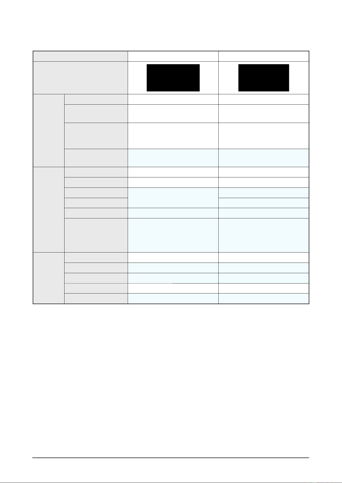
Product Specification
Model Name HT-BD1250 HT-BD2
Photo
Video
Resolution
Default
Audio
Factory
When
which has correct EDID
When
TV which has incorrect
EDID
Remark
DD
Dolby
dts
dts-HD
Re-encoding (into dts) X
HD
output on HDMI 1.3
SMPS 2 trans 2 trans
Default 480p 480p
connected the TV
connected the
Plus decoding
TrueHD decoding
HD HRA decoding
MA decoding
audio bit stream
Maximum resolution for TV input Maximum resolution for TV input
480p 480p
HT-BD1250 can also output 480i/480p
resolution with Blu-ray Disc
(dts-HD Master Audio essential)
dts-HD MA Essential
dts-HD HRA
TrueHD
DD+
HT-BD2 can also output 480i/480p
resolution with Blu-ray Disc
dts-HD MA
dts-HD HRA
TrueHD
DD+
H/W
Deck Draw type Plastic Cover Slot-In
Pick
Up 5G VE Pickup 4G VE Pickup
Micom SANYO SANYO
Front
↔Loader One Board P-ATA
Main
: application, X: non-application
Samsung Electronics 2-9
Product Specification
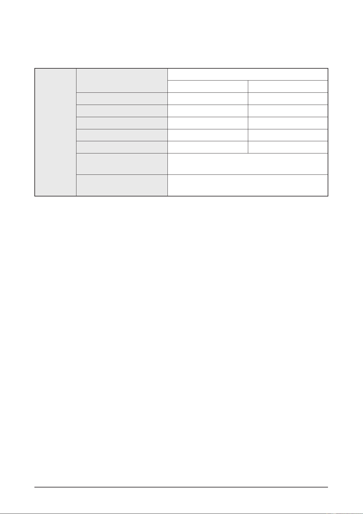
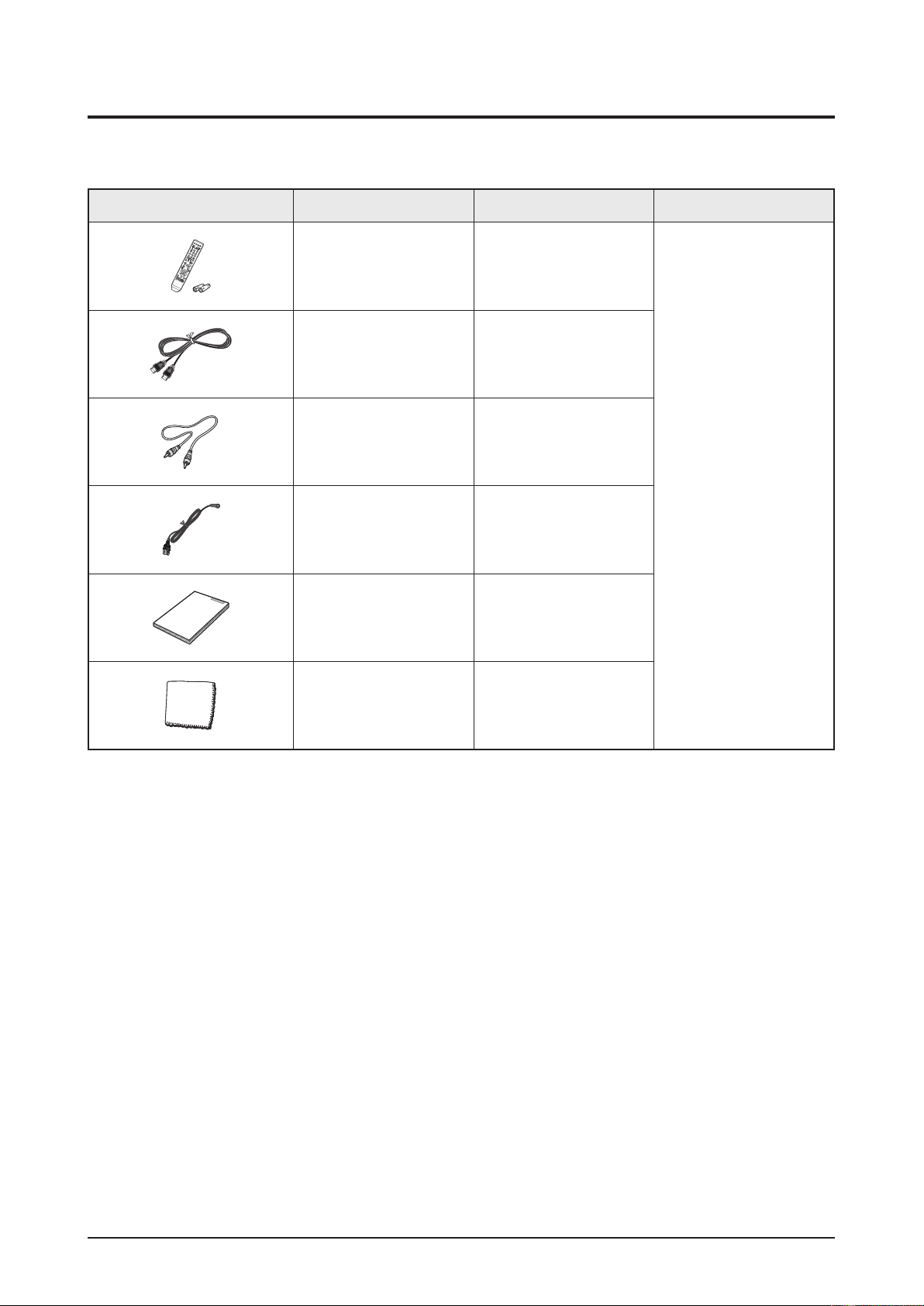
2-4 Accessories
2-4-1 Supplied Accessories
Accessories Item Item code Remark
Remote Control
Battery
HDMI Cable AH39-00923A
Audio Cable AH39-40001V
FM Antenna AH42-00021A
User’s Manual
AH59-02144K
4301-000116
AH68-02178S
AH68-02183M
Samsung Service Center
Cloth Clean AH81-02286C
2-10 Samsung Electronics

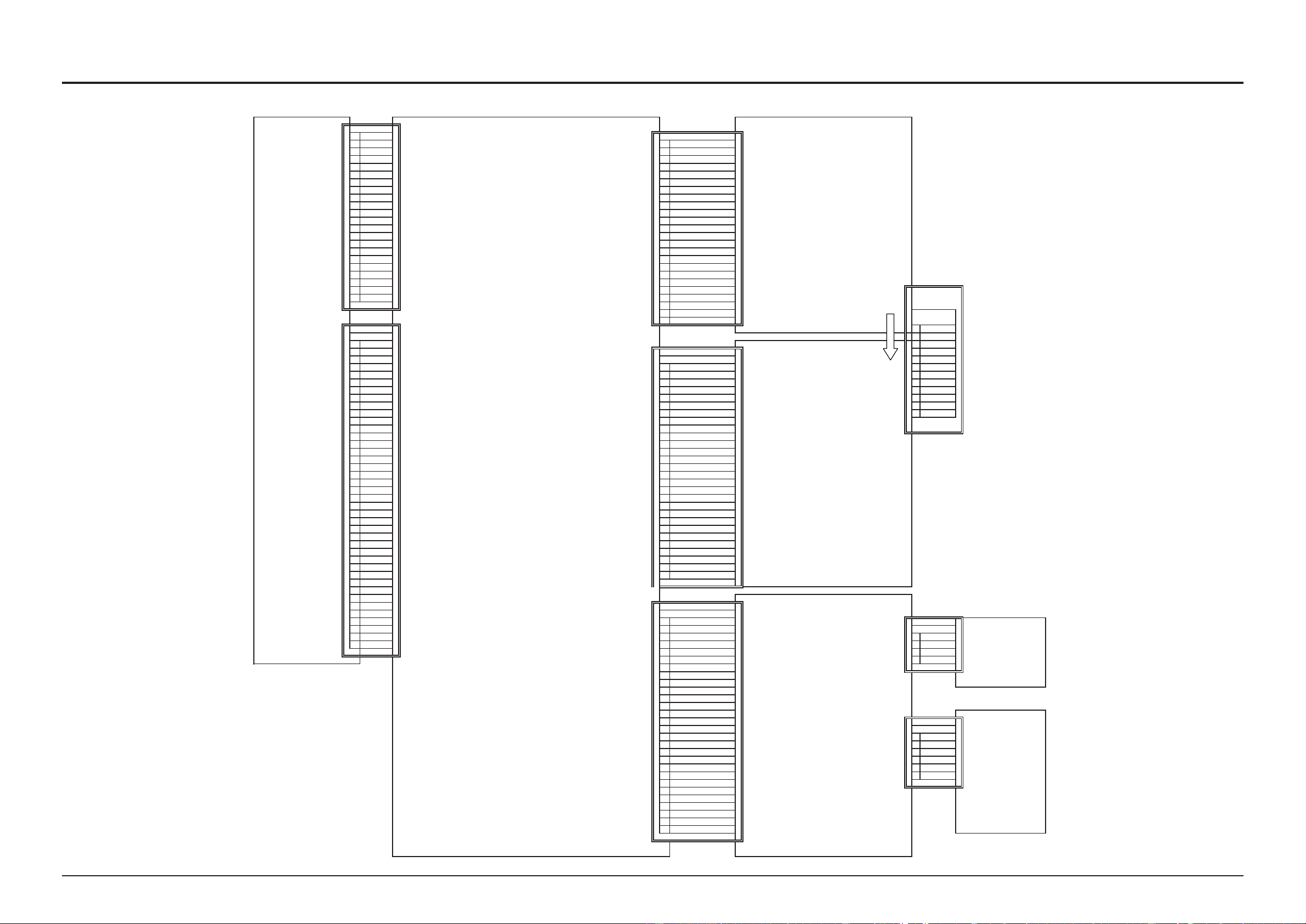
6. PCB Diagram
6-1 Wiring Diagram.................................................................................................6-2
6-2 FRONT PCB Top ............................................................................................... 6-3
PCB Diagram
6-3
6-4
6-5
6-6
6-7
6-8
6-9
6-10
6-1
FRONT PCB Bottom ........................................................................................6-5
KEY PCB Top .................................................................................................... 6-6
KEY PCB Bottom ..............................................................................................6-8
AMP PCB Top ...................................................................................................6-9
AMP PCB Bottom .............................................................................................6-11
MAIN PCB Top .................................................................................................. 6-13
MAIN PCB Bottom ............................................................................................6-16
SMPS PCB Top ................................................................................................. 6-18
1 SMPS PCB Bottom ...........................................................................................6-19
Samsung Electronics 6-1
PCB Diagram
1 SW3
2 LDO+ 1 ST 5.4V
3 LDO- 2 ST 5.4V
4 CLOSE 3 ST 5.4V
5 OPEN 4 GND
6 GND 5 GND
7 W 6 GND
8 V 7 D5.4V
9 U 8 D5.4V
10 GND 9 D5.4V
11 H+ 10 GND
12 HU+ 11 GND
13 HU- 12 GND
14 HW+ 13 FE 12V
15 HW- 14 FE 12V
16 H- 15 FE GND
17 HV- 16 FE GND
18 HV+ 17 NC
19 SLD2+ 18 POWER_ON
20 SLD2- 19 NC
21 SLD1+ 20 DGND
22 SLD1- 21 VFD +4.6V
22 VFD -4.6V
23 -34V
24 DGND
1 AGND
2 +12V
1 5V 3 AGND
2 SA_INT 4 -5V
3 SAOUT2+ 5 +35V
4 SAOUT1+ 1 6 +35V
5 SAOUT1- 2 7 +35V
6 SAOUT2- 3 AVGND 8 GND
7 GND 4 MIC_PDN 9 GND
8 CDLD 5 SD(POWER) 10 -35V
9 CDVR 6 RESET(POWER) 11 -35V
10
DVDCDMPD 7 12 -35V
11 DVDVR 8 AUOUT3
12 DVDLD 9 AUOUT2
13 TEMP 10 AUOUT1
14 VDMPD 11 LRCKOUT
15 GND 12 BCLKOUT
16 BDSLEEP 13 GND
17 GAINSW 14 GND
18 VREFB 15 AV 3.3V
19 VREFB 16 DS 5V
20 5V 17 EXT_MUTE(PWM)
21 RFID 18 RESET(PWM)
22 RFIN 19 SO(PWM)
23 GG 20 CS(PWM)
24 HH 21 SCK(PWM)
25 EE
22 SI(PWM)
26 FF 23 SW_MUTE
27 DD 24 FAN_PWR
28 CC 25 FAN_SEN
29 BB 26 MIC
30 AA 27 AL 5.4V
31 GND 28 AVGND
32 TD33 FD34 TILT35 TILT+
36 FD+
37 TD+ 1 UART_BT_RX
38 GND 2 UART_BT_TX
39 BDLD 3 MIC_SENSE 1 POWER_ON
40 BDHFM 4 VFD_FU_CLK 2 DGND
5 VFD_FU_DATA 3 KEY
6 VFD_CE 4 + 5.6V
7 GND
8 SMPS_VFD(+4.6V)
9 VFD 4.6V(-)
10 SMPS_VFD -34V
11 GND
12 AL 5.4V
13 MIC_DATA
14 POWER_LED
15
16 MIC_CLK 1 5V
TNI_YEK2YEK1_HCUOT_REWOP71
18 3 KEY_SDA
19 BTRST 4 KEY_SCL
20 BUZZER 5 KEY_RESET
21 GND 6 D_GND
22 VOL_DOWN
23 VOL_UP
24 TC_SDA
25 TOUCH_CLK
26 TOUCHRST
27 TOUCH_INT
28 GND
(TCON1)
FUNTION
(PCON1)
POWER
FRONT
(SCN2
)
MAIN
POWER(J3)
LOADER1
(DJ3)
AMP
(CON12)
(PCN1
)
DECK ASSY
SMPS
6-1 Wiring Diagram
6-2 Samsung Electronics
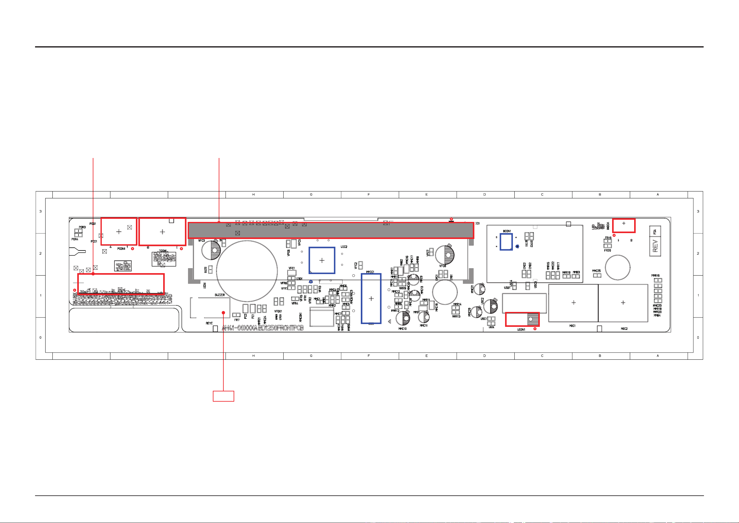
6-2 FRONT PCB Top
IJK
IJK
VCON1
BCON1
MMIC1
UIC2
UCON1
TCON1
IC1
PCON1
FCON1
1 2
PCB Diagram
TP4
Samsung Electronics 6-3
 Loading...