

Page 1
5 Troubleshooting
Notes: 1. Before troubleshooting, setup the PC’s display as below.
• Resolution: 1280 x 1024
• H-frequency: 64 kHz
• V-frequency: 60 Hz
2. If no picture appears, make sure the power cord is correctly connected.
3. Check the following circuits.
• No raster appears: SMPS PCB, Main PCB
• 12V develop but no screen: Main PCB
• 12V does not develop: SMPS PCB
4. If you push and hold the “EXIT” button for more than 5 seconds, the monitor automatically returns
to the factory preset.
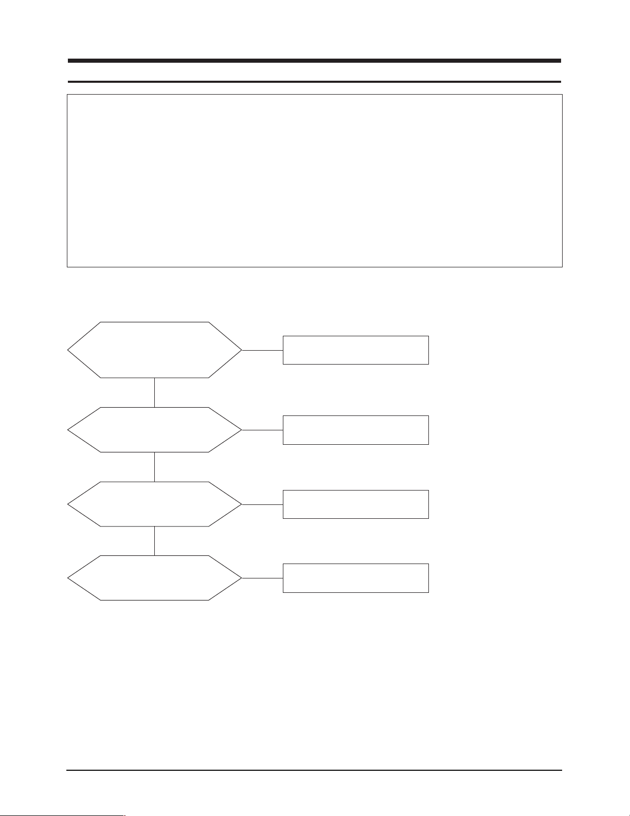
5-1 No Power (GY17CS*)
When Pin 5 of CN101 is 0V
❇
does proper DC 13V, DC 5V
appear at Pin 1, 2 and Pin 6, 7 of
CN101 separately?
Yes
When Pin 3 of IC102 is
DC 5V does proper DC 3.3V
appear at Pin 4 of IC102?
Yes
When Pin 5 of IC101 is
DC 5V does proper DC 5V appear
at Pin 2, 3 of IC101?
Yes
When Pin 3 of IC103 is
DC 5V does proper DC 2.5V
appear at Pin 2 of IC103?
No
Change IP board.
No
Check IC102 and related circuit.
No
Check IC101 and related circuit.
No
Check IC103 and related circuit.
❇ 0V means power on state.
GY17CS*/GY17VS* 5-1
Page 2
5 Troubleshooting
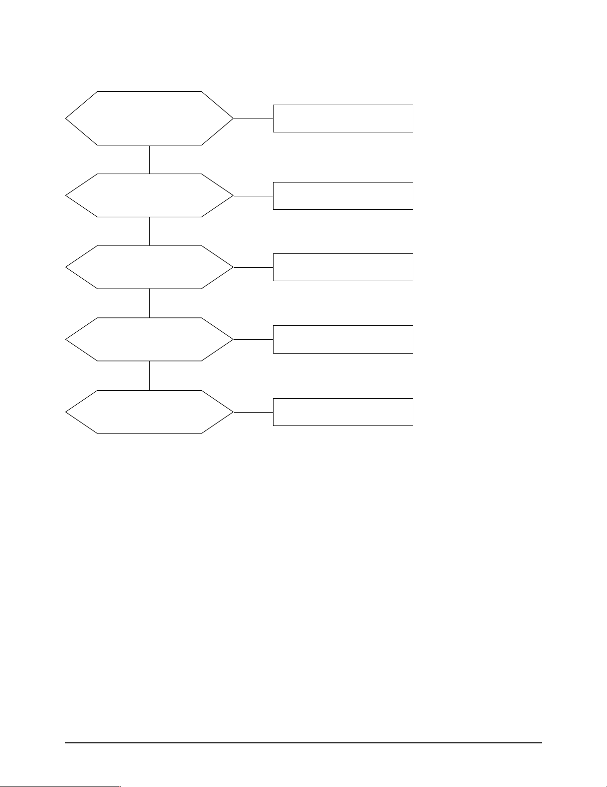
5-2-1 No Power (GY17VS* - Main 2)
When Pin 5 of CN101 is 0V
❇
does proper DC 13V, DC 5V
appear at Pin 1, 2 and 7 of
CN101 separately?
Yes
When Pin 2 of IC101 is 0V
does proper DC 3.3V appear at
Pin 7 and 8 of IC101?
Yes
When Pin 4 of IC101 is DC 2.5V
does proper DC 5V appear at
Pin 5 and 6 of IC101?
Yes
Does proper DC5V, DC 3.3 V
appear at Pin 3, 4 of IC102?
Yes
No
No
No
No
Change IP board.
Check IC101, IC102 and
related circuit.
Check IC101 and related circuit.
Check IC102 and related circuit.
When Pin 1 of IC103 is
DC 5V does proper DC 2.5V
appear at Pin 3 of IC103?
❇ 0V means power on state.
No
Check IC103 and related circuit.
5-2 GY17CS*/GY17VS*
Page 3

5-2-2 No Power (GY17VS* - Main 1)
5 Troubleshooting
When Pin 4 of CN102 is 0V
❇
does proper DC 13V, 5V
appear at Pin 8, 9 and 3 of
CN102 separately?
Yes
When Pin 2 of IC 105 is 0V
does proper DC 5V appear at
Pin 7 and 8 of IC105?
Yes
When Pin 4 of IC 105 is 5V
does proper DC 5V appear at
Pin 5 and 6 of IC105?
Yes
Does proper DC 3.3 V
appear at Pin 3 of IC101?
No
No
No
No
Change IP Board.
Check IC105, IC113 and
related circuit.
Check IC105 and related circuit.
Check IC101 and related circuit.
❇ 0V means power on state.
GY17CS*/GY17VS* 5-3
Page 4

5 Troubleshooting
5-3-1 No Video (GY17CS*, GY17VS* - Main 2)
Check signal cable connection and power.
1 2
Is there R, G, B input at R427, R428 and R429?
R302, R303, R305, R304 and RA301 ~ RA312?
Does the output signal appear at R401~R420?
Do X303 oscillate properly?
Yes
Yes
Does sync appear at Pin 8 and 10 of IC201?
Yes
Is there sync and data output
3 4 5 6
Yes
No
No
No
No
No
Replace or
check related circuit.
Check input part.
Check IC201 and related circuit.
Check the power related to
IC303 and output part.
Check the LVDS_EN at
R301 is high or not.
Normal state is high.
Yes
There are DC 5V at Pin 1, 2 and 3 of CN401?
Yes
Replace LCD panel.
No
Check the IC101
and related circuit.
5-4 GY17CS*/GY17VS*
Page 5

5-3-2 No Video (GY17VS* - Main 1 )
Check signal cable connection and power.
5 Troubleshooting
1 2
Do X301 and X501 oscillate properly?
Yes
Is there R, G, B input at R161, R165 and R171?
Yes
Does sync appear at Pin 8 and 10 of IC106?
Yes
Is there sync and data output
R175, R176, R178, R179 and RA101 ~ RA112?
3 4 5 6
Yes
Does the output signal appear at R401~R420?
No
No
No
No
No
Replace or
check related circuit.
Check input part.
Check IC106 and related circuit.
Check the power related to
IC109 and output part.
Check the LVDS_EN at
R105 is high or not.
Normal state is high.
Yes
There are DC 5V at Pin 1, 2 and 3 of CN401?
Yes
Replace LCD Panel.
No
Check the IC105
and related circuit.
GY17CS*/GY17VS* 5-5
Page 6

5 Troubleshooting
WAVEFORMS
1
3 4
2
5 6
5-6 GY17CS*/GY17VS*
 Loading...