

Samsung Galaxy Grand 2 LTE, SM-G7105 Disassembly
Level
7.
Disassembly and Assembly Instructions
7-1.
Repair
2
7-1-1.
※ Caution
1) Be care of scratch and molding damage.
Disassembly
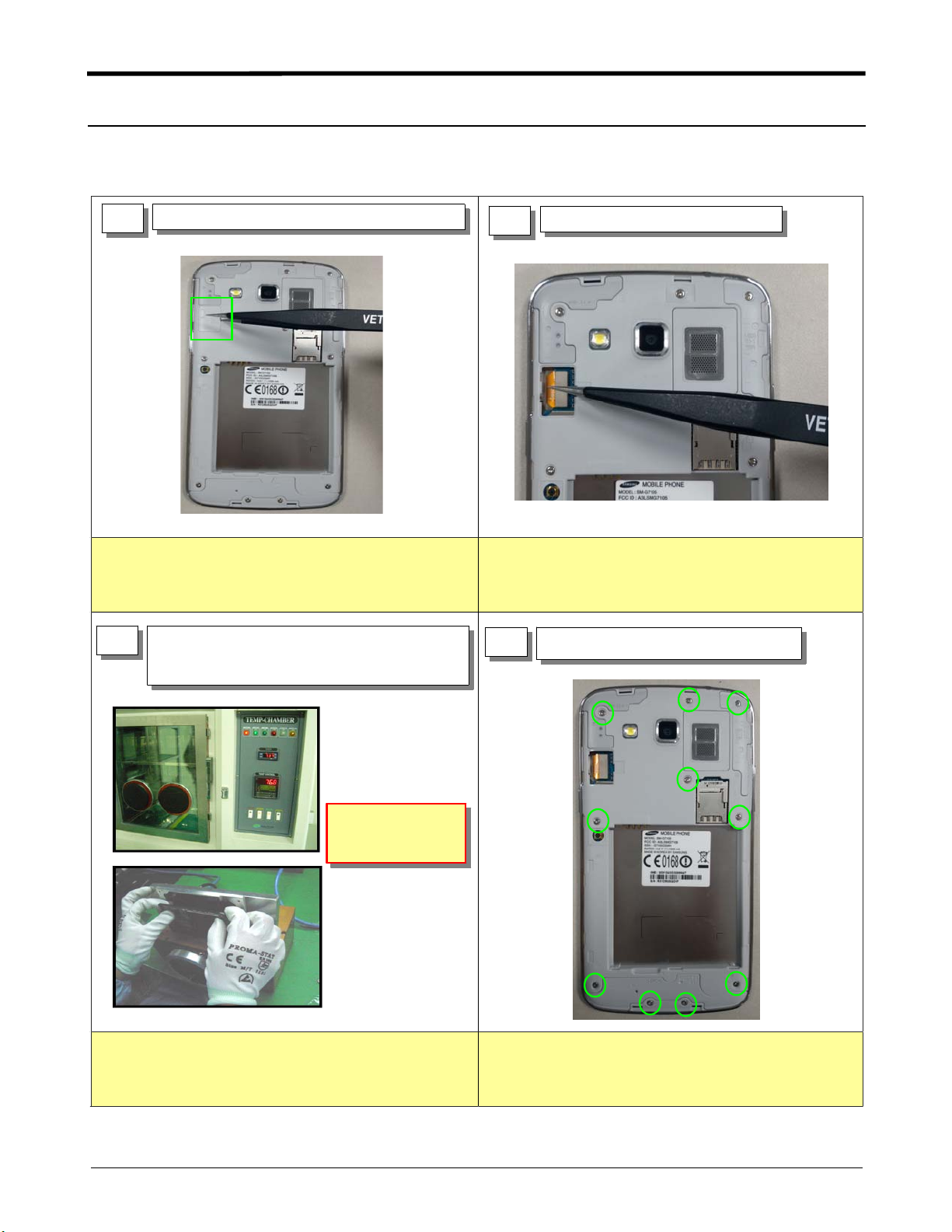
1) Disassemble LCD connector protect cover.
1
1) Separate the LCD connector.
2
※ Caution
1) Be care of scratch and molding damage.
2) Be care of damage to the FPCB.
1) Displace the temperature chamber for
3
※ Caution
1) Before disassembling, Use heating chamber.
2) Be care of scratch and molding damage.
10 minute
2) Detach the TSP/LCD Assay using Vaccum jig
AIR pressure
5~7 kgf/cm
4
1) Unscrew the 10 points.
※ Caution
1) Be care of scratch and molding damage.
7-1
Confidential and proprietary-the contents in this service guide subject to change without prior notice.
Distribution, transmission, or infringement of any content or data from this document without Samsung’swritten authorization is strictly prohibited.
Level2Repair
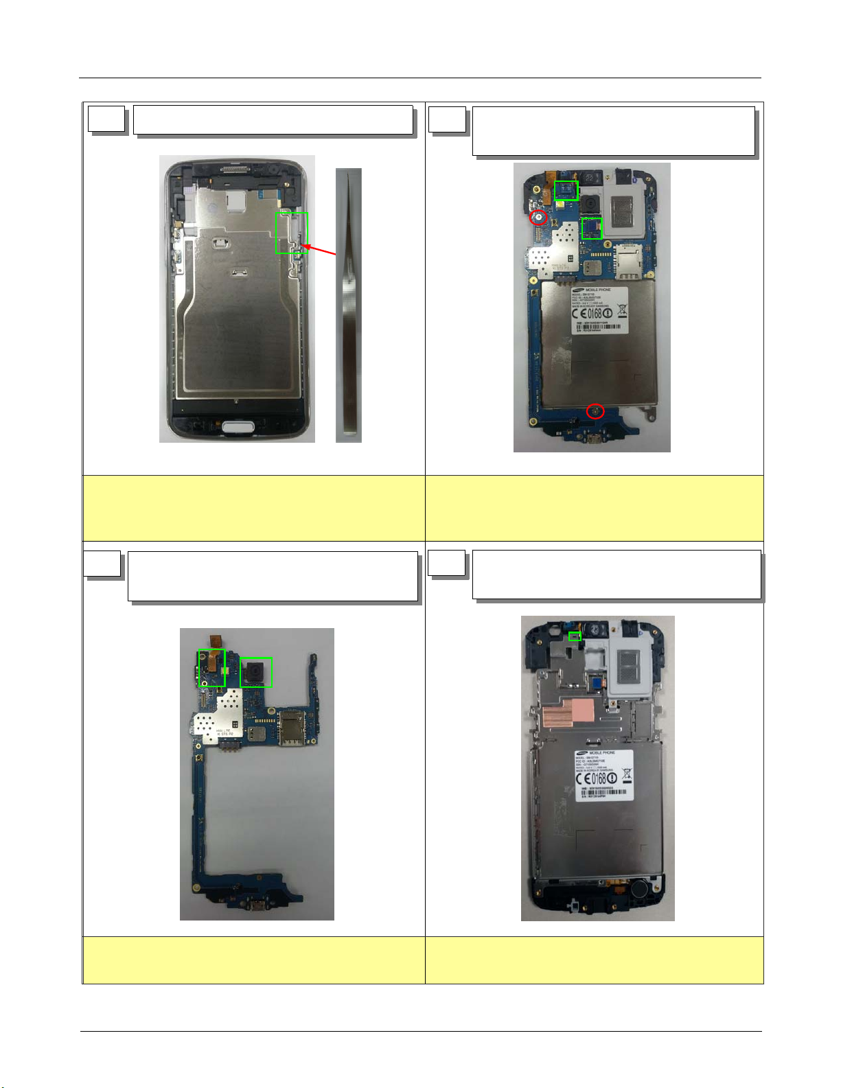
5
1) Detach the PBA/Sheildcan Assay
※ Caution
1) Be care of damage to the EARJACK Module.
2) Be care of damage to the CAMERA.
6
1) Disassemble the RCV, Sensor, SPK from PBA.
2) Unscrew the 2 points.
※ Caution
1) Be care of damage to RCV.
2) It pushes this part at disassembly, and lift it
7
1) Separate the VGA, MEGA Camera from PBA
Array.
1) Be care of damage to the TSP FPCB.
8
1) Separate the Top dummy, Bottom dummy,
Speaker from hook.
1) Be care of scratch and molding damage.
2) Be care of damage to the TSP & LCD.
7-2
Confidential and proprietary-the contents in this service guide subject to change without prior notice.
Distribution, transmission, or infringement of any content or data from this document without Samsung’swritten authorization is strictly prohibited.
 Loading...