

Samsung FE-N500WX-XAA User Manual

This manual is made with 100% recycled paper.
F T Q 3 8 6 * /
F T Q 3 5 2 * /
F C Q 3 2 1 * /
F T Q 3 8 7 * /
F T Q 3 5 3 * /
F T Q 3 0 7 * /
Electric Range
installation manual
F E - R 3 0 0 *
F E - R 4 0 0 *
F E - R 5 0 0 *
F E - R 7 0 0 *
F E - N 30 0 *
F E - N 5 0 0 *
ENGLISH
imagine the possibilities
Thank you for purchasing this Samsung product.
To receive more complete service, please register
your product at
www.samsung.com/register
1-800-SAMSUNG(726-7864)
Installation-USA DG68-00108E-01_EN.indd 1 2011-03-18 �� 4:06:26
before you begin
About this mAnuAl
READ THESE INSTRUCTIONS COMPLETELY AND CAREFULLY.
Important note to the installer
• Read all instructions contained in these installation instructions before installing range.
• Remove all packing materials from the oven compartments before connecting the electrical supply
to the range.
• Observe all governing codes and ordinances.
• Be sure to leave these instructions with the consumer.
Important note to the consumer
Keep these instructions for the local electrical inspector’s use.
• As when using any appliance generating heat, there are certain safety precautions you should follow.
• Be sure your range is installed and grounded properly by a qualified installer or service technician.
• Make sure the wall coverings around the range can withstand the heat generated by the range.
• To eliminate the need to reach over the surface elements, cabinet storage space above the elements
should be avoided.
• The range should not be placed on a base.
FoR YouR sAFEtY
WARNING
WARNING If the information in this manual is not followed exactly, a fire or electrical
shock may result causing property damage, personal injury or death.
WARNING
WARNING Before beginning the installation, switch power off at the service panel and
lock the service disconnecting means to prevent power from being switched on accidentally. When the
service disconnecting means cannot be locked, securely fasten a prominent warning device, such as a
tag, to the service panel.
WARNING
WARNING This appliance must be properly grounded.
Anti-tiP DEViCE
TO REDUCE THE RISK OF TIPPING, THE APPLIANCE MUST BE SECURED BY PROPERLY
INSTALLING THE ANTI-TIP BRACKET PROVIDED WITH THIS APPLIANCE.
WARNING
WARNING
• ALL RANGES CAN TIP
• INJURY TO PERSONS COULD RESULT
• INSTALL ANTI-TIP BRACKET PACKED WITH RANGE
• SEE INSTALLATION MANUAL
If you pull the range out and away from the wall for any reason, make sure the Anti-Tip bracket is
engaged when the range is pushed back against the wall.
2_ Before you begin
Installation-USA DG68-00108E-01_EN.indd 2 2011-03-18 �� 4:06:26
preparing to install the range
REmoVE PACKAGinG
Remove packaging materials. Failure to remove packaging materials could result in damage to the
appliance.
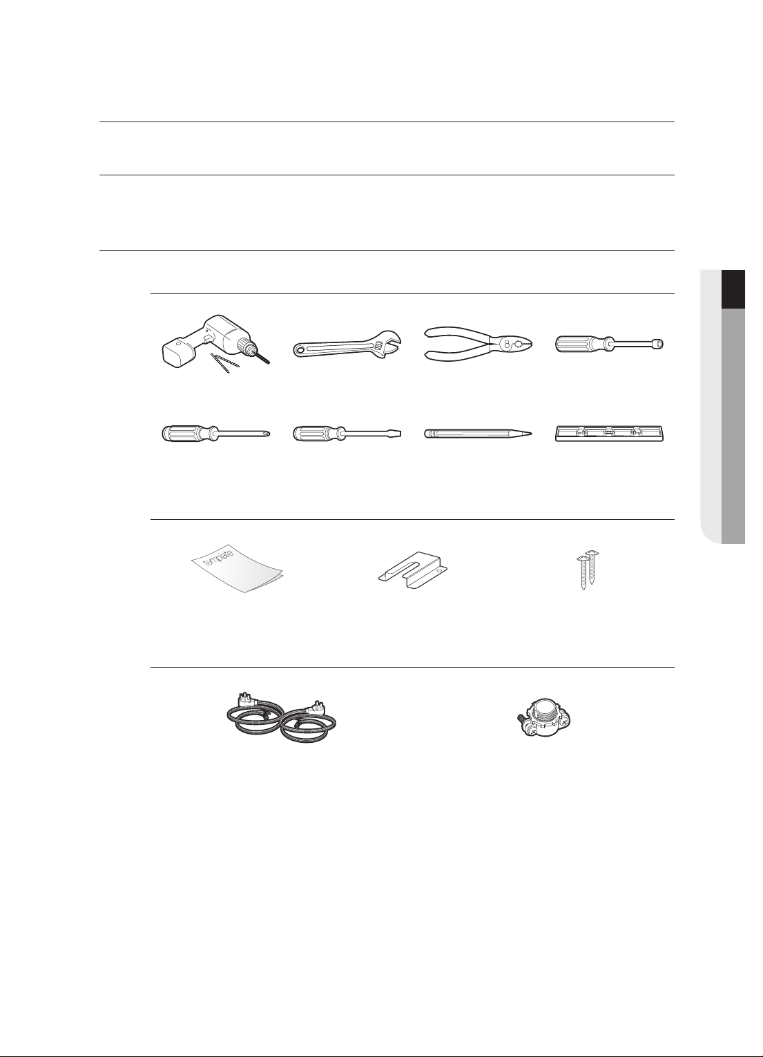
PREPARE tools & PARts
What tools you will need
Drill Adjustable Wrench Pliers
Phillips Screwdriver Flat Screwdriver Pencil Level
1
/4˝ Nut Driver
What’s included with your range
Template Anti-Tip Bracket Screws (2 ea)
What’s not included
01 PREPARING TO INSTALL
4-Wire Cord or 3-Wire Cord
(UL Approved 40 or 50 AMP)
Installation-USA DG68-00108E-01_EN.indd 3 2011-03-18 �� 4:06:26
Strain Relief
(For Conduit Installation Only)
Preparing to install the range _3

ChECKinG thE instAllAtion sitE
Clearances and dimensions
To install the range, refer to the following figure.
For installation in CANADA, a Free-standing range is not to be installed closer than 12mm
from any adjacent surface.
CAUTION
CAUTION This range has been designed to comply with the maximum allowable wood
cabinet temperatures of 194°F. Make sure the wall covering, countertops and cabinets around the
range can withstand the heat (up to 194°F) generated by the range. If not, discoloration, delamination
or melting may occur.
3”
25”
24”
3”
6”
36”
B
A
A : Cabinet opening
30” For U.S.A,
30”
24”
30”~31” For CANADA.
B : Acceptable electrical
outlet area
Minimum dimensions
IMPORTANT To eliminate the risk of burns or fire caused by reaching over heated surface
units, cabinet storage space located above the surface units should be avoided. If cabinet storage is to
be provided, the risk can be reduced by installing a range hood that projects horizontally a minimum of
5” beyond the bottom of the cabinets.
30”
* 30”
** 15”
* 30” minimum clearance between the top
of the cooking surface and the bottom of
an unprotected wood or metal cabinet;
or 24” minimum when the bottom of the
wood or metal cabinet is protected by not
less than 1/4” flame retardant millboard
covered with not less than no.28 MSG
sheet steel, 0.015” stainless steel, 0.024”
aluminum or 0.020” copper.
** 15” minimum between the countertop and
the adjacent cabinet bottom.
4_ Preparing to install the range
Installation-USA DG68-00108E-01_EN.indd 4 2011-03-18 �� 4:06:27
 Loading...