

Samsung dvd-tv Service Manual
DVD Television
Chassis : C16A
Model: DW21G5VDX/XEF DW21G5VDX/BWT
DW21G5VDX/XEU DW21G5VDX/NWT
DW21G5VDX/XEN DW21G5VDX/VWT
DW21G5VDX/XEG
DVD Television Cassette Recorder CONTENTS
Precautions
Specifications
Disassembly and Reassembly
Alignment and Adjustment (Electrical)
Troubleshooting
Exploded View and Parts List
Electric Parts List
Block Diagram
Schematic Diagrams
1.
2.
3.
4.
5.
6.
7.
8.
9.
1. Precautions
1-1 Safety Precautions
1. Be sure that all of the built-in protective
devices are replaced. Restore any missing
protective shields.
2. When reinstalling the chassis and its
assemblies, be sure to restore all protective
devices, including: nonmetallic control knobs
and compartment covers.
3. Make sure that there are no cabinet openings
through which people—particularly
children—might insert fingers and contact
dangerous voltages. Such openings include
the spacing between the picture tube and the
cabinet mask, excessively wide cabinet
ventilation slots, and improperly fitted back
covers.
If the measured resistance is less than 1.0
megohm or greater than 5.2 megohms, an
abnormality exists that must be corrected
before the unit is returned to the customer.
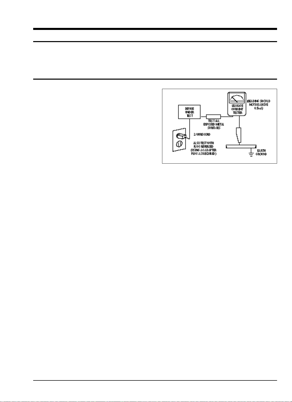
4. Leakage Current Hot Check (Figure 1-1):
Warning: Do not use an isolation
transformer during this test. Use a leakagecurrent tester or a metering system that
complies with American National Standards
Institute (ANIS C101.1, Leakage Current for
Appliances), and Underwriters Laboratories
(UL Publication UL1410, 59.7).
5. With the unit completely reassembled, plug
the AC line cord directly into the power
outlet. With the unit’s AC switch first in the
ON position and then OFF, measure the
current between a known earth ground (metal
water pipe, conduit, etc.) and all exposed
metal parts, including: antennas, handle
brackets, metal cabinets, screwheads and
control shafts. The current measured should
not exceed 0.5 milliamp. Reverse the powerplug prongs in the AC outlet and repeat the
test.
Fig. 1-1 AC Leakage Test
6. Antenna Cold Check:
With the unit’s AC plug disconnected from the
AC source, connect an electrical jumper across
the two AC prongs. Connect one lead of the
ohmmeter to an AC prong. Connect the other
lead to the coaxial connector.
7. X-ray Limits:
The picture tube is especially designed to prohibit X-ray emissions. To ensure continued
X-ray protection, replace the picture tube only
with one that is the same type as the original.
Carefully reinstall the picture tube shields and
mounting hardware; these also provide X-ray
protection.
8. High Voltage Limits:
High voltage must be measured each time servicing is done on the B+, horizontal deflection
or high voltage circuits. Correct operation of
the X-ray protection circuits must be
reconfirmed whenever they are serviced.
(X-ray protection circuits also may be called
“horizontal disable” or “hold-down”.)
Heed the high voltage limits. These include
the X–ray Protection Specifications Label, and
the Product Safety and X-ray Warning Note on
the service data schematic.
Precautions
Samsung Electronics 1-1
Follow these safety, servicing and ESD precautions to prevent damage and protect against potential
hazards such as electrical shock and X-rays.

1-1 Safety Precautions (Continued)
9. High voltage is maintained within specified
limits by close-tolerance, safety-related
components and adjustments. If the high
voltage exceeds the specified limits, check
each of the special components.
10. Design Alteration Warning:
Never alter or add to the mechanical or
electrical design of this unit. Example: Do not
add auxiliary audio or video connectors. Such
alterations might create a safety hazard. Also,
any design changes or additions will void the
manufacturer’s warranty.
11. Hot Chassis Warning:
Some TV receiver chassis are electrically
connected directly to one conductor of the AC
power cord. If an isolation transformer is not
used, these units may be safely serviced only
if the AC power plug is inserted so that the
chassis is connected to the ground side of the
AC source.
To confirm that the AC power plug is inserted
correctly, do the following: Using an AC
voltmeter, measure the voltage between the
chassis and a known earth ground. If the
reading is greater than 1.0V, remove the AC
power plug, reverse its polarity and reinsert.
Re-measure the voltage between the chassis
and ground.
12. Some TV chassis are designed to operate with
85 volts AC between chassis and ground,
regardless of the AC plug polarity. These units
can be safely serviced only if an isolation
transformer inserted between the receiver and
the power source.
13. Some TV chassis have a secondary ground
system in addition to the main chassis ground.
This secondary ground system is not
isolated from the AC power line. The two
ground systems are electrically separated by
insulating material that must not be defeated
or altered.
14. Components, parts and wiring that appear to
have overheated or that are otherwise
damaged should be replaced with parts that
meet the original specifications. Always
determine the cause of damage or overheating, and correct any potential hazards.
15. Observe the original lead dress, especially
near the following areas: Antenna wiring,
sharp edges, and especially the AC and high
voltage power supplies. Always inspect for
pinched, out-of-place, or frayed wiring. Do
not change the spacing between components
and the printed circuit board. Check the AC
power cord for damage. Make sure that leads
and components do not touch thermally hot
parts.
16. Picture Tube Implosion Warning:
The picture tube in this receiver employs
“integral implosion” protection. To ensure
continued implosion protection, make sure
that the replacement picture tube is the same
as the original.
17. Do not remove, install or handle the picture
tube without first putting on shatterproof
goggles equipped with side shields. Never
handle the picture tube by its neck. Some
“in-line” picture tubes are equipped with a
permanently attached deflection yoke; do not
try to remove such “permanently attached”
yokes from the picture tube.
18. Product Safety Notice:
Some electrical and mechanical parts have
special safety-related characteristics which
might not be obvious from visual inspection.
These safety features and the protection they
give might be lost if the replacement component differs from the original—even if the
replacement is rated for higher voltage,
wattage, etc.
Components that are critical for safety are
indicated in the circuit diagram by shading,
( ) or ( ).
Use replacement components that have the
same ratings, especially for flame resistance
and dielectric strength specifications.
A replacement part that does not have the
same safety characteristics as the original
might create shock, fire or other hazards.
Precautions
1-2 Samsung Electronics

1-2 Servicing Precautions
1. Servicing precautions are printed on the
cabinet. Follow them.
2. Always unplug the unit’s AC power cord from
the AC power source before attempting to: (a)
Remove or reinstall any component or
assembly, (b) Disconnect an electrical plug or
connector, (c) Connect a test component in
parallel with an electrolytic capacitor.
3. Some components are raised above the printed
circuit board for safety. An insulation tube or
tape is sometimes used. The internal wiring is
sometimes clamped to prevent contact with
thermally hot components. Reinstall all such
elements to their original position.
4. After servicing, always check that the screws,
components and wiring have been correctly
reinstalled. Make sure that the portion around
the serviced part has not been damaged.
5. Check the insulation between the blades of the
AC plug and accessible conductive parts
(examples: metal panels, input terminals and
earphone jacks).
6. Insulation Checking Procedure: Disconnect the
power cord from the AC source and turn the
power switch ON. Connect an insulation
resistance meter (500V) to the blades of the AC
plug.
The insulation resistance between each blade
of the AC plug and accessible conductive parts
(see above) should be greater than 1 megohm.
7. Never defeat any of the B+ voltage interlocks.
Do not apply AC power to the unit (or any of
its assemblies) unless all solid-state heat sinks
are correctly installed.
8. Always connect a test instrument’s ground
lead to the instrument chassis ground before
connecting the positive lead; always remove
the instrument’s ground lead last.
Precautions
Samsung Electronics 1-3
Warning1: First read the “Safety Precautions” section of this manual. If some unforeseen circumstance creates a conflict between
the servicing and safety precautions, always follow the safety precautions.
Warning2: An electrolytic capacitor installed with the wrong polarity might explode.

1. Some semiconductor (“solid state”) devices
are easily damaged by static electricity. Such
components are called Electrostatically
Sensitive Devices (ESDs); examples include
integrated circuits and some field-effect
transistors. The following techniques will
reduce the occurrence of component damage
caused by static electricity.
2. Immediately before handling any semicon
ductor components or assemblies, drain the
electrostatic charge from your body by
touching a known earth ground. Alternatively,
wear a discharging wrist-strap device. (Be
sure to remove it prior to applying power—
this is an electric shock precaution.)
3. After removing an ESD-equipped assembly,
place it on a conductive surface such as
aluminum foil to prevent accumulation of
electrostatic charge.
4. Do not use freon-propelled chemicals. These
can generate electrical charges that damage
ESDs.
5. Use only a grounded-tip soldering iron when
soldering or unsoldering ESDs.
6. Use only an anti-static solder removal device.
Many solder removal devices are not rated as
“anti-static”; these can accumulate sufficient
electrical charge to damage ESDs.
7. Do not remove a replacement ESD from its
protective package until you are ready to
install it. Most replacement ESDs are
packaged with leads that are electrically
shorted together by conductive foam,
aluminum foil or other conductive materials.
8. Immediately before removing the protective
material from the leads of a replacement ESD,
touch the protective material to the chassis or
circuit assembly into which the device will be
installed.
9. Minimize body motions when handling
unpackaged replacement ESDs. Motions such
as brushing clothes together, or lifting a foot
from a carpeted floor can generate enough
static electricity to damage an ESD.
Precautions
1-4 Samsung Electronics
1-3 Precautions for Electrostatically Sensitive Devices (ESDs)
Precautions
Samsung Electronics 1-5
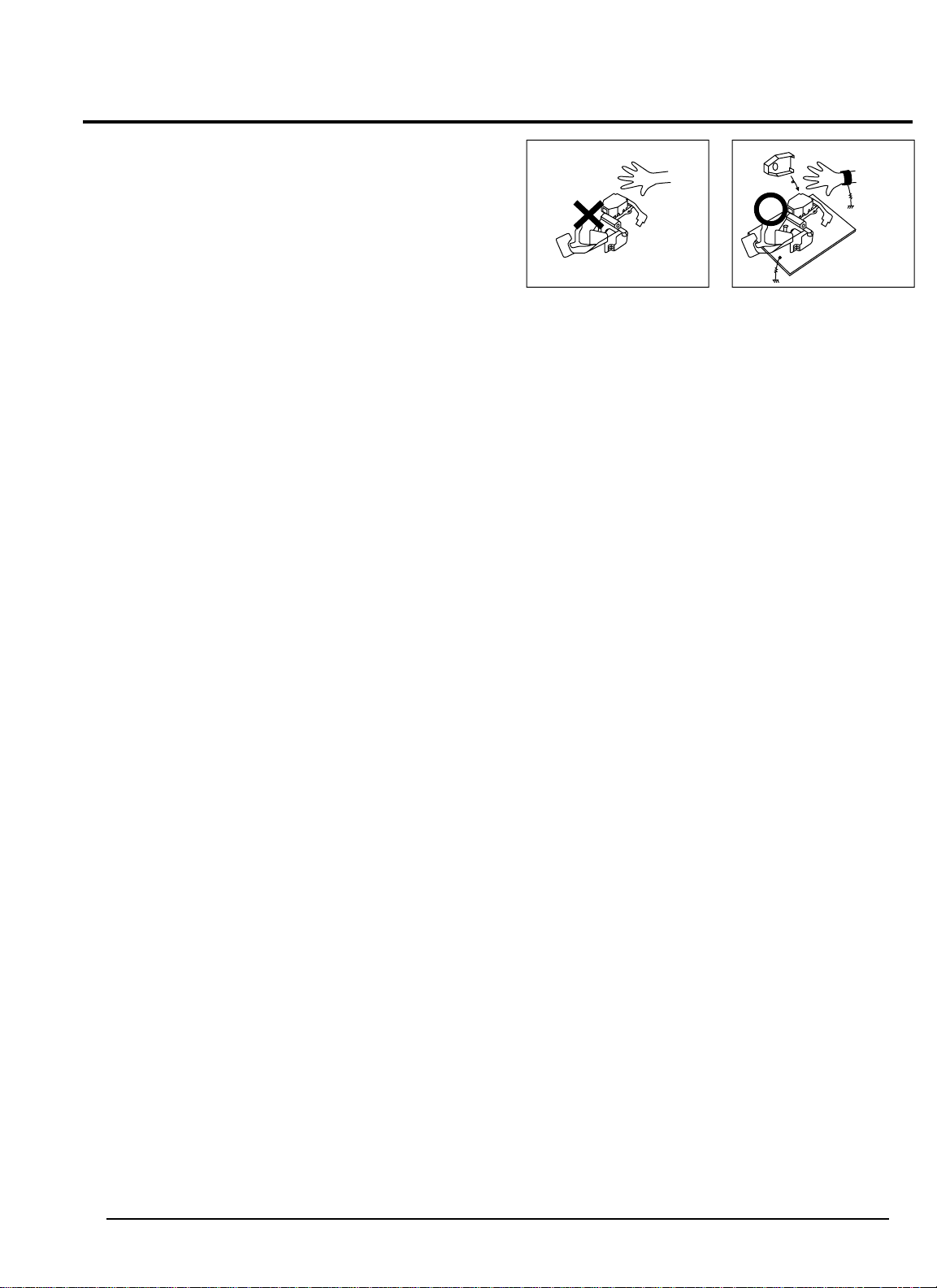
1-4 Handling the optical pick-up
The laser diode in the optical pick up may suffer electrostatic breakdown because of potential static electricity from clothing and your body.
The following method is recommended.
(1) Place a conductive sheet on the work bench (The
black sheet used for wrapping repair parts.)
(2) Place the set on the conductive sheet so that the
chassis is grounded to the sheet.
(3) Place your hands on the conductive sheet(This
gives them the same ground as the sheet.)
(4) Remove the optical pick up block
(5) Perform work on top of the conductive sheet. Be
careful not to let your clothes or any other static
sources to touch the unit.
Be sure to put on a wrist strap grounded to the sheet.
Be sure to lay a conductive sheet made of copper etc.
Which is grounded to the table.
Fig.1-3
(6) Short the short terminal on the PCB, which is in-
side the Pick-Up ASS’Y, before replacing the PickUp. (The short terminal is shorted when the PickUp Ass’y is being lifted or moved.)
(7) After replacing the Pick-up, open the short terminal
on the PCB.
THE UNIT
WRIST-STRAP
FOR GROUNDING
1M
1M
CONDUCTIVE SHEET

Precautions
1-6 Samsung Electronics
1-5 Pick-up disassembly and reassembly
1-5-1 Disassembly
1) Remove the power cable.
2) Switch SW3 on Deck PCB to “OFF” before
removing the Flat-Cable.
( Inserted into Main PCB DCN1. See Fig. 1-4)
3) Disassemble the Deck.
4) Disassemble the Deck PCB.
1-5-2 Assembly
1) Replace the Pick-up.
2) Assemble the Deck PCB.
3) Reassemble the Deck.
4) Insert Flat-Cable into Main PCB DCN1 and switch
SW3 on Deck PCB to “ON”. (See Fig 1-4)
Note : If the assembly and disassembly are not done in correct sequence, the Pick-up may be damaged.

Samsung Electronics 2-1
2-1. Specifications
TELEVISION PART
Colour systems PAL(option) / SECAM(option) (UK;PAL)
TV standards L/L’(option), B/G(option), D/K(option) (UK;I)
Number of channels 100 programmes
Reception range/cable TV Hyperband/interband tuner
Aerial input 75 Ohms, coaxial cable
DISC
DVD (DIGITAL VERSATILE DISC) Reading Speed : 3,49 m/sec.
Approx. Play Time (Single sided, Single Layer Disc) : 135 min.
CD : 12 Cm Reading Speed : 1,2 to 1,4 m/sec.
Maximum Play Time : 74 min.
CD : 8 Cm Reading Speed : 1,2 to 1,4 m/sec.
Maximum Play Time : 20 min.
CD : 12 Cm Reading Speed : 1,2 to 1,4 m/sec.
Maximum Play Time : 74 min. (Video + Audio)
GENERAL
Power supply 220-240V~, 50Hz (110-260V~, 50/60Hz; option)
Consumption 85W
Audio output power 7Watts x 2
Number of loudspeakers 2
Tube size 21” (51cm)
Tube type BLACK MATRIX
Sockets 2 SCART(SCART1 : FULL RGB SCART) ON THE REAR.
(SCART2 : MONITOR OUT) ON THE REAR.
1 RCA input (audio and video2) on the front
Earphones output (3.5 mm mini-jack)
1 aerial/cable TV coaxial input
Dimensions (W x D x H)/Weight 606 X 513 X 505mm / 39.5Kg
Operating temperature 5°C - 35°C
Relative humidity 10% - 75%
The descriptions and characteristics given in this booklet are given for information purposes only and
are subject to modification without notice.

4-2 Factory (“Service”) Mode
Alignment and Adjustments (Electrical)
4. Alignment and Adjustments (Electrical)
4-1 Preadjustment
4-1-1 Factory Mode
1. Do not attempt these adjustments in the Video
Mode.
2. The Factory Mode adjustments are necessary
when either the EEPROM (IC902) or the CRT
is replaced.
3. Do not tamper with the “Adjustment” screen
of the Factory Mode menu. This screen is
intended only for factory use.
4-1-2 When EEPROM (IC902) Is Replaced
1. When IC902 is replaced all adjustment data
revert to initial values. It is necessary to reprogram this data.
2. After IC902 is replaced, warm up the TV for
10 seconds.
4-1-3 When CRT Is Replaced
Make the following adjustments after setting up
purity and convergence:
White Balance
Sub-Brightness
Vertical Center
Vertical Size
Horizontal Size
4-2-1 Procedure for the “Adjustment” Mode
1. This mode uses the standard remote control.
The Service Mode is activated by: (1) pressing
the “FACTORY” service key on the local-keyboard, or (2) by entering the following remotecontrol sequence (within 2 seconds):
STAND-BY →DISPLAY →MENU→ MUTE→
POWER ON
2. The “SERVICE (FACTORY)” message will be
displayed. The Service Mode has three components: Adjustment, Option Bytes and Reset.
3. Access the Adjustment Mode by pressing the
“VOLUME” keys ( Up or Down). The adjustment parameters are listed in the accompanying table, and selected by pressing the CHANNEL keys (▲,▼).
4. Selection sequences for the
PAL/SECAM B/G, L systems:
down or up key:
TXP>SBT>SCT>SCR>STT>BCR>BLG>RG>
GG>BG>PWL>SC>SL>VA>PUS>PHS>GRE>
BB>CDL>BKS>PEW>PEP>PEUC>PELC>
PDL>VSC>HP>HB>TC>WS
5. The VOLUME keys increase or decrease the
adjustment values, (stored in the
non-volatile memory) when Adjustment Mode
is cancelled.
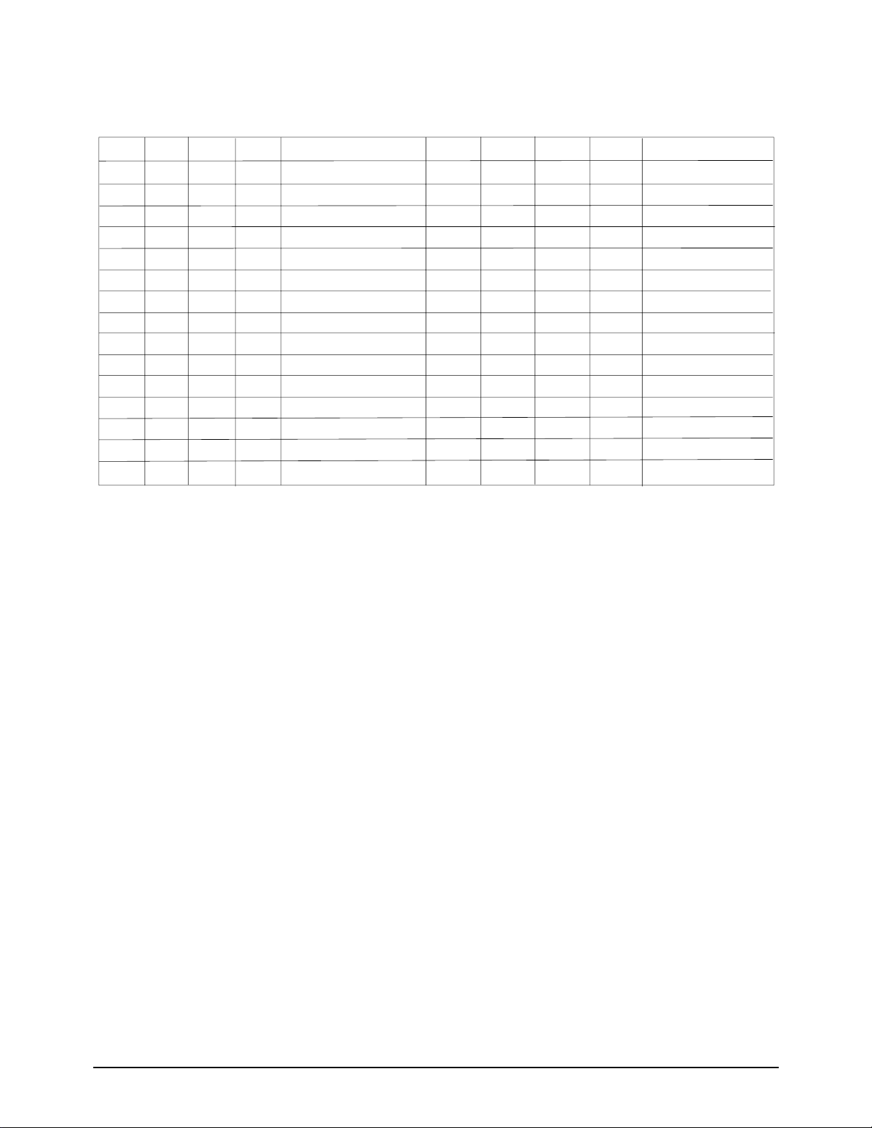
4-2-2 Adjust
NOTE : PVS, VA, PHS, NVS, NHS parameters must be aligned using
both the 50 Hz and 60 Hz vertical-field rates.
4-2-3 AGING Mode (Reference Only)
This pattern is used for pre-heating the CRT during manufacturing--it is accessed in the
factory by twice pressing the "FACTORY" key .
Even if the TV power is cut off, the Aging Mode is not cancelled.
The "AGING" marking is displayed on the screen.
The AGING mode is cancelled by repressing the "FACTORY" key.
Alignment and Adjustments (Electrical)
OSD
TXP
SBT
SCT
SCR
STT
BLR
BLG
RG
GG
BG
PWL
SC
SL
VA
PVS
Initial
4
6
10
6
9
8
8
32
32
32
15
11
27
12
26
Adjust
Fix
Fix
Fix
Fix
Fix
Fix
Fix
Range
0-7
0-23
0-23
0-13
0-13
0-15
0-15
0-63
0-63
0-63
0-15
0-63
0-63
0-63
0-63
Function
Osd Position
Sub Brigh
Sub Contrast
Sub Color
Sub Tint
Low Light R
Low Light G
High Light R
High Light G
High Light B
Peak white level
S-Correction
Vertical Slope
Vertical Amplitu
Pal vertical shift
Adjust
Fix
Fix
Fix
Fix
Fix
Fix
Fix
Fix
Fix
Fix
Fix
Fix
Initial
34
1
0
11
0
30
2
0
0
7
32
32
32
32
1
OSD
PHS
GRE
BB
CDL
BKS
REW
PEP
PEUC
PELC
PDL
VSC
HP
HB
TC
WS
Range
0-63
0-1
0-1
0-15
0-1
0-15
0-15
0-63
0-63
0-15
0-63
0-63
0-63
0-63
0-63
Function
Pal Horizon Shift
Greenish level
Blue Screen
Cathode Drive Level
Black Stretcher
EW
EW Parabola
Under Corner
Lower Corner
H-Paralleogram
Horizontal Bow
EW Trapezium
White Stretch
4-2-4 OPTION
Alignment and Adjustments (Electrical)
NO
1
2
3
4
5
6
7
8
9
OSD
HELP MSG
LANGUAGE
SYSTEM
ATS OPTION
AUTO CLOCK
S-Modulation
TTX
TTX DEFAULT
Adjust
ON
EUROPE
CF
ON
OFF(Fix)
54%
ON
FLOF
Range
ON/OFF
EUROPE/RUSSIA/ARAB
CF/CI/CW/CX/CB/CII
ON/OFF
ON/OFF
54%/80%/100%
ON/OFF
FLOF/LIST
4-2-5 RESET
The Reset Mode is used during factorying inspection
Function Reset : After Factorying Reset, the following items itens revert to their initial values.
1. Volume 11
2. Program Channel 0
3. P- STD MEMORY
4. Auto Power OFF
5. NR OFF
6. Skip(Store/Clear) ALL CLEAR
Cautim : When the EEPROM is replaced ; all items revert to their initial values.

Alignment and Adjustments (Electrical)
4-3 Other Adjustments
4-3-1 General
1. Usually, a color TV needs only slight
touch-up adjustment upon installation.
Check the basic characteristics such as height,
horizontal and vertical sync and focus.
2. The picture should have good black and white
details. There should be no objectionable
color shading; if color shading is present,
perform the purity and convergence adjustments described below.
3. Use the specified test equipment or its
equivalent.
4. Correct impedance matching is essential.
5. Avoid overload. Excessive signal from a sweep
generator might overload the front-end of the
TV. When inserting signal markers, do not
allow the marker generator to distort test
results.
6. Connect the TV only to an AC power source
with voltage and frequency as specified on the
backcover nameplate.
7. Do not attempt to connect or disconnect any
wires while the TV is turned on. Make sure
that the power cord is disconnected before
replacing any parts.
8. To protect against shock hazard, use an
isolation transformer.
4-3-2 Automatic Degaussing
A degaussing coil is mounted around the
picture tube, so that external degaussing after
moving the TV should be unnecessary. But
the receiver must be properly degaussed upon
installation.
The degaussing coil operates for about 1
second after the power is switched ON. If the
set has been moved or turned in a different
direction, disconnect its AC power for at least
10 minutes.
If the chassis or parts of the cabinet become
magnetized, poor color purity will result. If
this happens, use an external degaussing coil.
Slowly move the degaussing coil around the
faceplate of the picture tube and the sides and
front of the receiver. Slowly withdraw the coil
to a distance of about 6 feet before removing
power.
4-3-3 High Voltage Check
CAUTION: There is no high voltage
adjustment on this chassis. The B+ power
supply must be set to +130 volts (Full color
bar input and normal picture level).
1. Connect a digital voltmeter to the second
anode of the picture tube.
2. Turn on the TV. Set the Brightness and
Contrast controls to minimum (zero beam
current).
3. The high voltage should not exceed 30KV.
4. Adjust the Brightness and contrast controls to
both extremes. Ensure that the high voltage
does not exceed 30KV under any conditions.

Alignment and Adjustments (Electrical)
4-3-4 FOCUS Adjustment
1. Input a black and white signal.
2. Adjust the tuning control for the clearest picture.
3. Adjust the FOCUS control for well defined scanning lines in the center area of the screen.
4-3-5 Screen Adjustment
1. Turn to the ACTIVE channel.
2. Adjust the VR screen for a normal picture is (no blooming or flyback line).
3. Adjust the FOCUS control for well defined scanning lines in the center area of the screen.
4-3-6 Purity Adjustment
1. Warm up the receiver for at least 20 minutes.
2. Plug in the CRT deflection yoke and tighten the clamp screw.
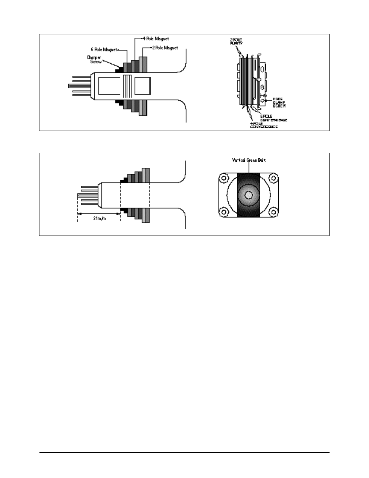
3. Plug the convergence yoke into the CRT and set in as shown in Fig. 5-1.
4. Input a black and white signal.
5. Fully demagnetize the receive by applying an external degaussing coil.
6. Turn the CONTRAST and BRIGHTNESS controls to maximum.
7. Loosen the clamp screw holding the yoke. Slide the yoke backward or forward to provide
vertical green belt. (Fig. 5-2).
8. Tighten the convergence yoke.
9. Slowly move the deflection yoke forward, and adjust for the best overall green screen.
10. Temporarily tighten the deflection yoke.
11. Produce blue and red rasters by adjusting the low-light controls. Check for good purity
in each field.
12. Tighten the deflection yoke.
Alignment and Adjustments (Electrical)
TILT (TC)
AFC BOW (HB)
H SIZE
PIN COMP (PEP)
H POSITION (PHS)
V LINEARITY (SL)
UP CPIN (PEUC)
V S CORRECTION (SC)
AFC ANGLE (HP)
V POSITION (PVS)
LO CPIN (PELC)
V SIZE(VA)
4-3-7 I C BUS GEOMETRIC Adjust
2
Alignment and Adjustments (Electrical)
4-3-8 White Balance Adjustment
4-4-7 (A) HIGH-LIGHT ADJUSTMENT
1. Input either a Lion Head or a “pure white” pattern.
2. Warm up the TV for 30 minutes.
3. Check the data in the Service Mode
4. Adjust RG, BG in the Factory Mode.
5-4-7 (B) LOW-LIGHT ADJUSTMENT
1. Automatically accomplished during the high-light adjustment.
Fig. 5 -1 Convergence Magnet Assembly
Fig. 5-2 Center Convergence Adjustment
Alignment and Adjustments (Electrical)
4-3-8 Center Convergence Adjustment
1. Warm up the receiver for at least 20 minutes.
2. Adjust the two tabs of the 4 pole magnets to
change the angle between them. Superimpose
the red and blue vertical lines in the center
area of the screen.
3. Adjust the Brightness and Contrast controls for
a well defined picture.
4. Adjust the two-tab pairs of the 4 pole magnets,
and change the angle between them.
Superimpose the red and the blue vertical
lines in the center area of the screen.
5. Turn the both tabs at the same time, keeping
the angle constant, and superimpose the red
and blue horizontal line in the center of the
screen.
6. Adjust the two-tab pairs of the 6-pole magnets
to superimpose the red and blue line onto the
green. (Changing the angle affects the vertical
lines, and rotating both magnets affects the
horizontal lines.)
7. Repeat adjustments 2~6, if necessary.
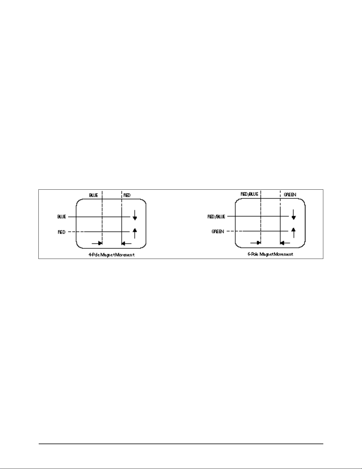
8. Since the 4-pole magnets and 6-pole magnets
interact, the dot movement is complex
(Fig. 5-3).
Fig 5-3 Center Convergence Adjustment

Troubleshooting
Samsung Electronics 5-1
5. Troubleshooting
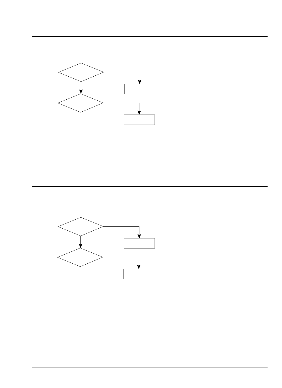
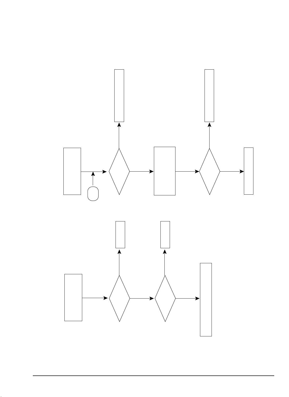
5-1 No Power (No Picture on)
Yes
Check
both terminal voltages
of C815 (130V)
Check both
terminal voltages of
C804 (280~300V).
Check D801S
F801,Q801.
No
Is IC801S Pin 3
19~22V?
Check IC801S
Check/Replace
DZ801,DZ808,
DZ802,PC801S
No
Yes
No
Yes
Check
Voltage of 80V, 15V, 20V,
13V power line..
Check whether
each power line
is short or open.
No
No
Yes
Is IC901
Pin 64 Voltage 5V?
Check H.V SYNC on
IC901 Pins 36,37
Check/Replace
IC901.
Check
IC901 Pin 20 is High
when power is On.
Check/Replace
IC902.
Check the voltage
of TU01S.
Yes
Yes
No
No
Yes

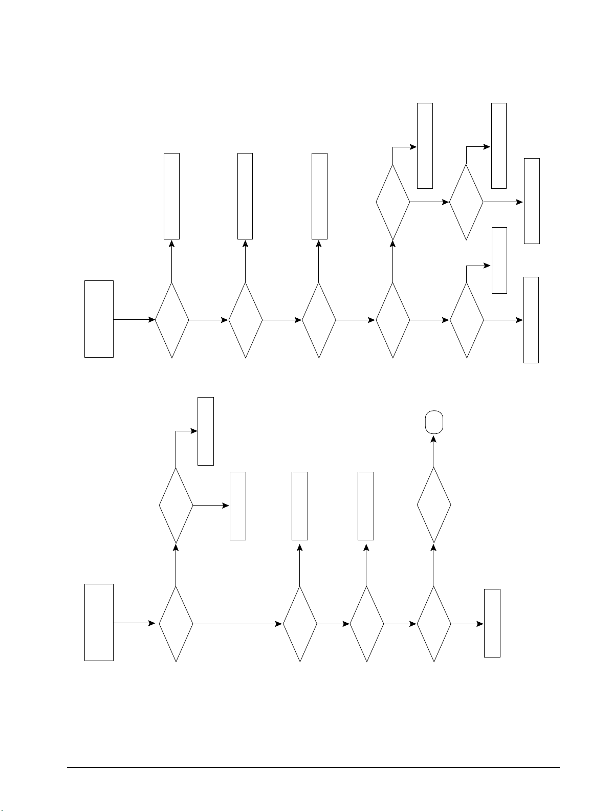
5-2 No Power (No LED On)
Troubleshooting
5-2 Samsung Electronics
Check IC901 #31
No
Check IC901 #52, #53
Check after Bus
Line Open
Yes
Yes
Yes
Yes
Check IC904
No
Check another I2C
Bus Line.
No
No
Check IC805
Check D805
Check IC801S
Replace
Replace
Yes
No
No
Check IC901 #50~52
Replace
IC901
No

5-3 No RF Picture / Sound
Troubleshooting
Samsung Electronics 5-3
Check IC901 #52, #53
Check chroma inodule
H-out
Yes
Yes
Yes (No Sound)
Check Tuois
SDA,SCL
Check Q402,Q401
Replace
Replace
Replace
No
No
No
No
Check
c/module, R405,R435
R424,R425,D411,
D401
Yes
Check Tuner SIF
output?
No
Check Sound module
B+, 5V,8V
Check 8V, 5V
Power Line
No
No Picture
Yes
Yes
Yes
Sound Module Replace
Replace
Replace
Troubleshooting
5-4 Samsung Electronics
5-4 DVD PLAY NO PICTURE
Check CN201
y-cut,c-out
No
Check chroma module
No
Yes
Check DVD
Replace
Check CN201
D-L, D-R
No
Check Sound module
No
Yes
Check DVD
Replace
5-5 DVD PLAY NO SOUND

Troubleshooting
Samsung Electronics 5-5
5-6 No Picture (Sound OK)
1 Check the Brightness, Contrast and Color adjustments
2. Check: AV Picture
3. See Video Block Diagram
5-7 No Sound (Picture OK)
1. Check the Volume adjustment level.
2. Check AV Video
3. See Audio Block Diagram
5-8 RF Weak Signal (Playback, AV Mode OK)
1. Check Tuner (TU01S) B+. Check: 8V (IC802)
33V (DZ201). Check 5V (IC804)
5-9 No Vertical SCAN
1. Check R425, D401
2. Check IC301, #2
3. Check Chroma module Vertical-out Line
4. Check DY Connector
5-10 Horizontal Size
1. Check L406, C411, R421, Q403, D404, R413, R405
5-11 On-Screen Display Missing
1. Check IC901 #32, #33, 34
2. Check Chroma module
5-12 No Teletext
1. Check IC901 #30
2. Check IC901 #24 (CVBS)

Troubleshooting
5-6 Samsung Electronics
5-13 DVD Block Troubleshooting
LD is outputted
from object lens
at play key input?
Yes
Check open state from
DRIC4 to pick-up.
Check RIC1 and A,B,C,D input.
Check SIC3.
No Disc recognitionNo Disc recognition
A
B
A
No
FE om SOC1-25
is within specified
range?
Yes
No
SIC3-1,2 output
are mormal?
Yes
No
No Focus incomingNo Focus incoming
No focus incoming and
no disc occurs
Troubleshooting
Samsung Electronics 5-7
SLD, SIC-34
output is normal?
Yes
LED+, SLED-
SIC3-32,33 output are
normal?
Yes
Check the Sled Motor and connection
No pick-up home positingNo pick-up home positing
No
No
Check MIC1
Divide RQ1 emitter terminal
voltage and 5V real voltage
difference into 10ohm.
Open check in related circuit.
LD out pick-up replace.
Check MIC1
Check SIC3
B
RIC1-21 is 5V?
Yes
Yes
No
Current exceeds 0.1A?
Yes
No
NO LD CD ON
Troubleshooting
5-8 Samsung Electronics
MIRR, SIC1-157
output is normal?
Yes
Actual velocity occurs
at SIC1-34 terminal?
Yes
Actual velocity occurs
at SIC4-32,33 terminal?
Yes
TE occurs in
search range?
Focus On?
Yes
Check RIC1 Peripheral curcuit.
Check SIC1 Peripheral curcuit.
Time out due to many jump counts
No Search Operation
A
No
No
No
No
No No
FINE SEEK MIRR
signal(RIC1-46) is missing?
Yes
Yes
No
TZCO signal
(SIC1-24)is occurs?
Yes
No
Check RIC1-26 terminal.
Check SIC3 peripheral circuit.
Check SIC1 peripheral circuit.
Check DCN1 and pick-up.
Check MECHA.
Track incomming is
delayed?
Yes
No
TE is within
2V and 3V?
SIC1-33 output
are normal?
SIC3-28,29
terminaloutputs
are normal?
Yes
Yes
Yes
No
Pick-up transfer smooth.
Yes
No
FINE SEEK Check
RF AGCO, RIC1-72
Output level is
normal?
Yes
Check RIC1 peripheral circuit.
Check SIC1 peripheral circuit.
Check SIC3 peripheral circuit.
See "Fine Seek Check"
Check pick-up.
No
No

Troubleshooting
Samsung Electronics 5-9
SPD output is normal?
(SIC1-35)
Yes
SIC3-2 output(FG)
is normal?
Yes
SIC3-9 signal
MON is "H"?
Yes
Micom(MIC1) error
Check SIC3
Abnormal rotation of Abnormal rotation of
disc motordisc motor
No
No
No
No
No
No
MIC1-84,85 is
Open;"L","L"?
Close;"H","H"?
Yes
Yes
No
Check SIC3-35,36
output open/close
Yes
No
Check signal line state from
SIC3-35,36 to tray motor.
No Tray open/closeNo Tray open/close
RIC1-70 output
are normal?
Yes
Check path to RIC1 and SIC1
After resoldering SIC1
Check SIC3 soldering and power
Check SIC1, MIC1.
Check or replace disc motor
Check RIC1 doldering and power
Input of RF signal
is normal?(SIC1-15)
RIC1-71 output
is normal?
Yes
Check RIC1 peripheral
circuit and A,B,C,D
 Loading...