

Samsung DVDHR-730-A, DVDHR-732-A, DVDHR-734-A Service manual
DVD- RECORDER
ΠMulti format recording
DVD-RW/ DVD-R
´ Multi format playback
DVD / DVD-RW / DVD-R
CD / CD-R / CD-RW / MP3 / JPEG / DIVX
ˇ Recording mode
XP(1Hour) / SP(2Hour) / LP(4Hour) /
EP(6~8Hour)
¨ Progressive scan
ˆ Automatic Chapter product on
Ø 59mm Slim Design
DVD-RECORDER
Merit & Character regarding Product
SERVICE MANUAL
DVD-HR730A / DVD-HR732A / DVD-HR734A
DVD-HR730A / DVD-HR732A
DVD-HR734A
© Samsung Electronics Co., Ltd. DEC. 2006
Printed in Korea
AK82-01082A
This Service Manual is a property of Samsung Electronics Co.,Ltd.
Any unauthorized use of Manual can be punished under applicable
international and/or domestic law.
Chassis : Andes (3rd Generation)
BASIC : DVD-HR730A
Application Models
: DVD-HR730A / DVD-HR732A
/ DVD-HR734A
Application Areas
:
XEV, AFR, AND, SMR, UMG, XSG, XFA,
XSA, RAD, XSH, XSS, XST, XTL, SAM,
XSE, XSV, CHN, HAC, TAW, SEO, XEB,
XEC, XEE, XEF, XEG, XEO, XET
SERVICE
Manual
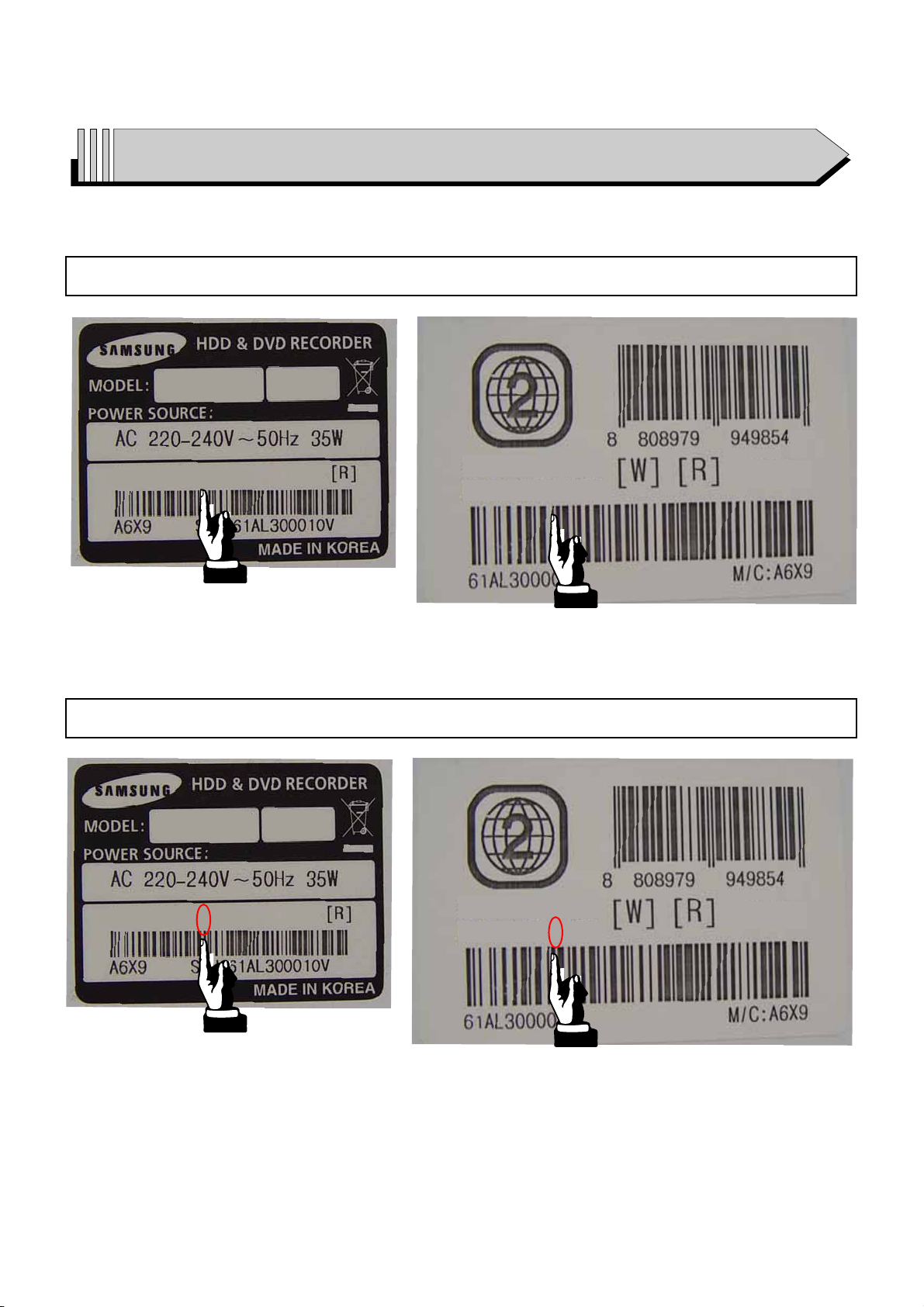
• The appearance of DVD-HR730 and appearance of DVD-HR730A is same.
However it will be able to distinguish with identifying them by Label-Rating.
How to identify them by Label-Rating ; See next page.
When servicing, be sure to confirm the model name on Label-Rating of Chassis-Rear.
ELECTRONICS

How to identify DVD-HR730A From DVD-HR730
DVD-HR730
DVD-HR730A
DVD-HR730
DVD-HR730/XEU
DVD-HR730
XEU
XEU
DVD-HR730
DVD-HR730/XEU
XEU
DVD-HR730A/XEU
DVD-HR730
DVD-HR730A/XEU
XEU
DVD-HR732
DVD-HR732A
How to identify DVD-HR732A From DVD-HR732
DVD-HR732
DVD-HR732XEU
DVD-HR732
XEU
XEU
DVD-HR732
DVD-HR732/XEU
XEU
DVD-HR732A/XEU
DVD-HR732
DVD-HR732A/XEU
XEU

DVD-HR734
DVD-HR734A
How to identify DVD-HR734A From DVD-HR734
DVD-HR734
DVD-HR734XEU
DVD-HR734
XEU
XEU
DVD-HR734
DVD-HR734/XEU
XEU
DVD-HR734A/XEU
DVD-HR734
DVD-HR734A/XEU
XEU

CONTENTS
1. Precautions 1-1 ~ 1-6
1-1 Safety Precaution (1-1)
1-2 Servicing Precautions (1-3)
1-3 ESD Precautions (1-4)
1-4 Handling the optical pick-up (1-5)
2. Product Specification 2-1 ~ 2-4
2-1 Product Specification (DVD-HR730A, DVD-HR734A Europe) (2-1)
2-2 Product Specification (DVD-HR730A, DVD-HR732A, DVD-HR734A Asia) (2-2)
2-3 Chassis Product Specification (2-3)
2-4 Option Product Specification (2-4)
3. Software Update 3-1 ~ 3-4
3-1 Drive Firmware Update (3-1)
3-2 Flash Update (3-3)
4. Disassembly and Reassembly 4-1 ~ 4-8
4-1 Cabinet and PCB (4-1)
4-2 PCB Location (4-8)
5. TroubleShooting 5-1 ~ 5-14
6. Exploded View and Parts List 6-1 ~ 6-6
6-1 Cabinet Assembly (DVD-HR730A, DVD-HR732A) (6-2)
6-2 Cabinet Assembly (DVD-HR734A) (6-4)
7. Electrical Parts List 7-1 ~ 7-18
8. Block Diagram 8-1 ~ 8-6
8-1 All Block Diagram (8-2)
8-2 DIC1 (MS8310) Block Diagram (8-3)
8-3 EIC1 (MS2697) Block Diagram (8-4)
8-4 PIC1 (TSB4AB1) Block Diagram (8-5)
8-5 VIC1 (SAA7136) Block Diagram (8-6)

9. Wiring Diagram 9-1 ~ 9-2
10. PCB Diagrams 10-1 ~ 10-10
10-1 S.M.P.S PCB (10-2)
10-2 Main PCB (10-4)
10-3 Jack PCB (10-6)
10-4 Function PCB (DVD-HR730A, DVD-HR732A) (10-8)
10-5 Function PCB (DVD-HR734A) (10-9)
11. Schematic Diagrams 11-1 ~ 11-16
Block Identification of Main PCB (11-2)
11-1 S.M.P.S (SMPS PCB) (11-3)
11-2 Main Connector (Main PCB) (11-4)
11-3 IEEE1394 (Main PCB) (11-5)
11-4 IVideo Decorder (Main PCB) (11-6)
11-5 MPEG-DECODER (Main PCB) (11-7)
11-6 MPEG-ENCODER (Main PCB) (11-8)
11-7 System Control (Jack PCB) (11-9)
11-8 TM Block (Jack PCB) (11-10)
11-9 Power (Jack PCB) (11-11)
11-10 Connection (Jack PCB) (11-12)
11-11 I/O (Jack PCB) (11-13)
11-12 I/O Switching (Jack PCB) (11-14)
11-13 Display Key (Jack PCB) (11-15)
11-14 Function (Function PCB) (DVD-HR730A / DVD-HR732A / DVD-HR734A)
(11-16)
CONTENTS

12. Operating Instructions 12-1 ~ 12-10
13. Circuit Operating Descriptions 13-1 ~ 13-12
13-1 Power (13-1)
13-2 SERVO (DVP Multi Drive) (13-4)
13-3 Video In/Out block (13-6)
13-4 Audio (13-9)
13-5 Tuner (13-10)
13-6 IF (13-11)
14. Reference Information 14-1 ~ 14-12
14-1 Introduction to DVD (14-1)
14-2 DVD-Video Fromat (14-3)
14-3 About IEEE1394 (14-9)
CONTENTS

Samsung Electronics 1-1
1. Precautions
1-1 Safety Precautions
1) Before returning an instrument to the customer,
always make a safety check of the entire instrument,
including, but not limited to, the following items:
(1) Be sure that no built-in protective devices are
defective or have been defeated during servicing.
(1)Protective shields are provided to protect both
the technician and the customer. Correctly replace
all missing protective shields, including any
removed for servicing convenience.
(2)When reinstalling the chassis and/or other assembly in the cabinet, be sure to put back in place
all protective devices, including, but not limited to,
nonmetallic control knobs, insulating fish papers,
adjustment and compartment covers/shields, and
isolation resistor/capacitor networks. Do not operate this instrument or permit it to be operated without all protective devices correctly installed and
functioning.
(2) Be sure that there are no cabinet openings through
which adults or children might be able to insert
their fingers and contact a hazardous voltage. Such
openings include, but are not limited to, excessively wide cabinet ventilation slots, and an improperly fitted and/or incorrectly secured cabinet back
cover.
(3) Leakage Current Hot Check-With the instrument
completely reassembled, plug the AC line cord
directly into a 230V(220V ~ 240V) AC outlet. (Do
not use an isolation transformer during this test.)
Use a leakage current tester or a metering system
that complies with American National Standards
institute (ANSI) C101.1 Leakage Current for
Appliances and Underwriters Laboratories (UL)
1270 (40.7). With the instrument’s AC switch first in
the ON position and then in the OFF position, measure from a known earth ground (metal water pipe,
conduit, etc.) to all exposed metal parts of the
instrument (antennas, handle brackets, metal cabinets, screwheads, metallic overlays, control shafts,
etc.), especially any exposed metal parts that offer
an electrical return path to the chassis.
Any current measured must not exceed 0.5mA.
Reverse the instrument power cord plug in the outlet and repeat the test. See Fig. 1-1.
Any measurements not within the limits specified
herein indicate a potential shock hazard that must
be eliminated before returning the instrument to
the customer.
Fig. 1-1 AC Leakage Test
(4) Insulation Resistance Test Cold Check-(1) Unplug
the power supply cord and connect a jumper wire
between the two prongs of the plug. (2) Turn on the
power switch of the instrument. (3) Measure the
resistance with an ohmmeter between the
jumpered AC plug and all exposed metallic cabinet
parts on the instrument, such as screwheads,
antenna, control shafts, handle brackets, etc. When
an exposed metallic part has a return path to the
chassis, the reading should be between 1 and 5.2
megohm. When there is no return path to the chassis, the reading must be infinite. If the reading is
not within the limits specified, there is the possibility of a shock hazard, and the instrument must be
repaired and rechecked before it is returned to the
customer. See Fig. 1-2.
Fig. 1-2 Insulation Resistance Test
(READING SHOULD
NOT BE ABOVE
0.5mA)
EARTH
GROUND
DEVICE
UNDER
TEST
TEST ALL
EXPOSED METER
SURFACES
2-WIRE CORD
ALSO TEST WITH
PLUG REVERSED
(USING AC ADAPTER
PLUG AS REQUIRED)
LEAKAGE
CURRENT
TESTER
Antenna
Terminal
Exposed
Metal Part
ohm
ohmmeter

Precautions
1-2 Samsung Electronics
2) Read and comply with all caution and safety related notes on or inside the cabinet, or on the chassis.
3) Design Alteration Warning-Do not alter or add to
the mechanical or electrical design of this instrument. Design alterations and additions, including
but not limited to, circuit modifications and the
addition of items such as auxiliary audio output
connections, might alter the safety characteristics of
this instrument and create a hazard to the user. Any
design alterations or additions will make you, the
servicer, responsible for personal injury or property
damage resulting therefrom.
4) Observe original lead dress. Take extra care to
assure correct lead dress in the following areas:
(1) near sharp edges, (2) near thermally hot parts (be
sure that leads and components do not touch thermally hot parts), (3) the AC supply, (4) high voltage,
and (5) antenna wiring. Always inspect in all areas
for pinched, out-of-place, or frayed wiring, Do not
change spacing between a component and the
printed-circuit board. Check the AC power cord for
damage.
5) Components, parts, and/or wiring that appear to
have overheated or that are otherwise damaged
should be replaced with components, parts and/ or
wiring that meet original specifications.
Additionally, determine the cause of overheating
and/or damage and, if necessary, take corrective
action to remove any potential safety hazard.
6) Product Safety Notice-Some electrical and mechanical parts have special safety-related characteristics
which are often not evident from visual inspection,
nor can the protection they give necessarily be
obtained by replacing them with components rated
for higher voltage, wattage, etc. Parts that have special safety characteristics are identified by shading,
an ( )or a ( )on schematics and parts lists. Use
of a substitute replacement that does not have the
same safety characteristics as the recommended
replacement part might create shock, fire and/or
other hazards. Product safety is under review continuously and new instructions are issued whenever appropriate.

Precautions
Samsung Electronics 1-3
1-2 Servicing Precautions
CAUTION : Before servicing units covered by this
service manual and its supplements, read and follow
the Safety Precautions section of this manual.
Note : If unforseen circumstances create conflict
between the following servicing precautions and any
of the safety precautions, always follow the safety precautions. Remember: Safety First.
1-2-1 General Servicing Precautions
(1) a. Always unplug the instrument’s AC power cord
from the AC power source before (1) re-moving
or reinstalling any component, circuit board,
module or any other instrument assembly, (2)
disconnecting any instrument electrical plug or
other electrical connection, (3) connecting a test
substitute in parallel with an electrolytic capacitor in the instrument.
b. Do not defeat any plug/socket B+ voltage inter-
locks with which instruments covered by this
service manual might be equipped.
c. Do not apply AC power to this instrument and
/or any of its electrical assemblies unless all
solid-state device heat sinks are correctly installed.
d. Always connect a test instrument’s ground lead
to the instrument chassis ground before connecting the test instrument positive lead. Always
remove the test instrument ground lead last.
Note : Refer to the Safety Precautions section ground
lead last.
(2) The service precautions are indicated or printed on
the cabinet, chassis or components. When servicing, follow the printed or indicated service precautions and service materials.
(3) The components used in the unit have a specified
flame resistance and dielectric strength.
When replacing components, use components
which have the same ratings. Components identified by shading, by( ) or by ( ) in the circuit diagram are important for safety or for the characteristics of the unit. Always replace them with the exact
replacement components.
(4) An insulation tube or tape is sometimes used and
some components are raised above the printed
wiring board for safety. The internal wiring is
sometimes clamped to prevent contact with heating components. Install such elements as they
were.
(5) After servicing, always check that the removed
screws, components, and wiring have been installed correctly and that the portion around the
serviced part has not been damaged and so on.
Further, check the insulation between the blades of
the attachment plug and accessible conductive
parts.
1-2-2 Insulation Checking Procedure
Disconnect the attachment plug from the AC outlet
and turn the power ON. Connect the insulation resistance meter (500V) to the blades of the attachment
plug. The insulation resistance between each blade of
the attachment plug and accessible conductive
parts(see note) should be more than 1 Megohm.
Note : Accessible conductive parts include metal panels, input terminals, earphone jacks, etc.

Precautions
1-4 Samsung Electronics
1-3 ESD Precautions
Electrostatically Sensitive Devices (ESD)
Some semiconductor (solid state) devices can be damaged easily by static electricity.
Such components commonly are called Electrostatically Sensitive Devices(ESD). Examples of typical ESD
devices are integrated circuits and some field-effect
transistors and semiconductor chip components. The
following techniques should be used to help reduce
the incidence of component damage caused by static
electricity.
(1) Immediately before handling any semiconductor
component or semiconductor-equipped assembly,
drain off any electrostatic charge on your body by
touching a known earth ground. Alternatively,
obtain and wear a commercially available discharging wrist strap device, which should be
removed for potential shock reasons prior to applying power to the unit under test.
(2) After removing an electrical assembly equipped
with ESD devices, place the assembly on a conductive surface such as aluminum foil, to prevent electrostatic charge buildup or exposure of the assembly.
(3) Use only a grounded-tip soldering iron to solder or
unsolder ESD devices.
(4) Use only an anti-static solder removal devices.
Some solder removal devices not classified as
“anti-static” can generate electrical charges sufficient to damage ESD devices.
(5) Do not use freon-propelled chemicals. These can
generate electrical charges sufficient to damage
ESD devices.
(6) Do not remove a replacement ESD device from its
protective package until immediately before your
are ready to install it.(Most replacement ESD
devices are packaged with leads electrically shorted together by conductive foam, aluminum foil or
comparable conductive materials).
(7) Immediately before removing the protective ma-
terials from the leads of a replacement ESD device,
touch the protective material to the chassis or circuit assembly into which the device will be
installed.
CAUTION : Be sure no power is applied to the chassis or circuit, and observe all other safety precautions.
(8) Minimize bodily motions when handling unpack-
aged replacement ESD devices. (Otherwise harmless motion such as the brushing together of your
clothes fabric or the lifting of your foot from a carpeted floor can generate static electricity sufficient
to damage an ESD device).

Precautions
Samsung Electronics 1-5
1-4 Handling the optical pick-up
The laser diode in the optical pick up may suffer electrostatic breakdown because of potential static electricity from clothing and your body.
The following method is recommended.
(1) Place a conductive sheet on the work bench (The
black sheet used for wrapping repair parts.)
(2) Place the set on the conductive sheet so that the
chassis is grounded to the sheet.
(3) Place your hands on the conductive sheet(This
gives them the same ground as the sheet.)
(4) Remove the optical pick up block
(5) Perform work on top of the conductive sheet. Be
careful not to let your clothes or any other static
sources to touch the unit.
Be sure to put on a wrist strap grounded to the
sheet.
Be sure to lay a conductive sheet made of copper
etc. Which is grounded to the table.
Fig.1-3
(6) Short the short terminal on the PCB, which is in-
side the Pick-Up ASS’Y, before replacing the PickUp. (The short terminal is shorted when the PickUp Ass’y is being lifted or moved.)
(7) After replacing the Pick-up, open the short termi-
nal on the PCB.
WRIST-STRAP
FOR GROUNDING
1M
THE UNIT
1M
CONDUCTIVE SHEET

Precautions
1-6 Samsung Electronics
MEMO
Samsung Electronics 2-1
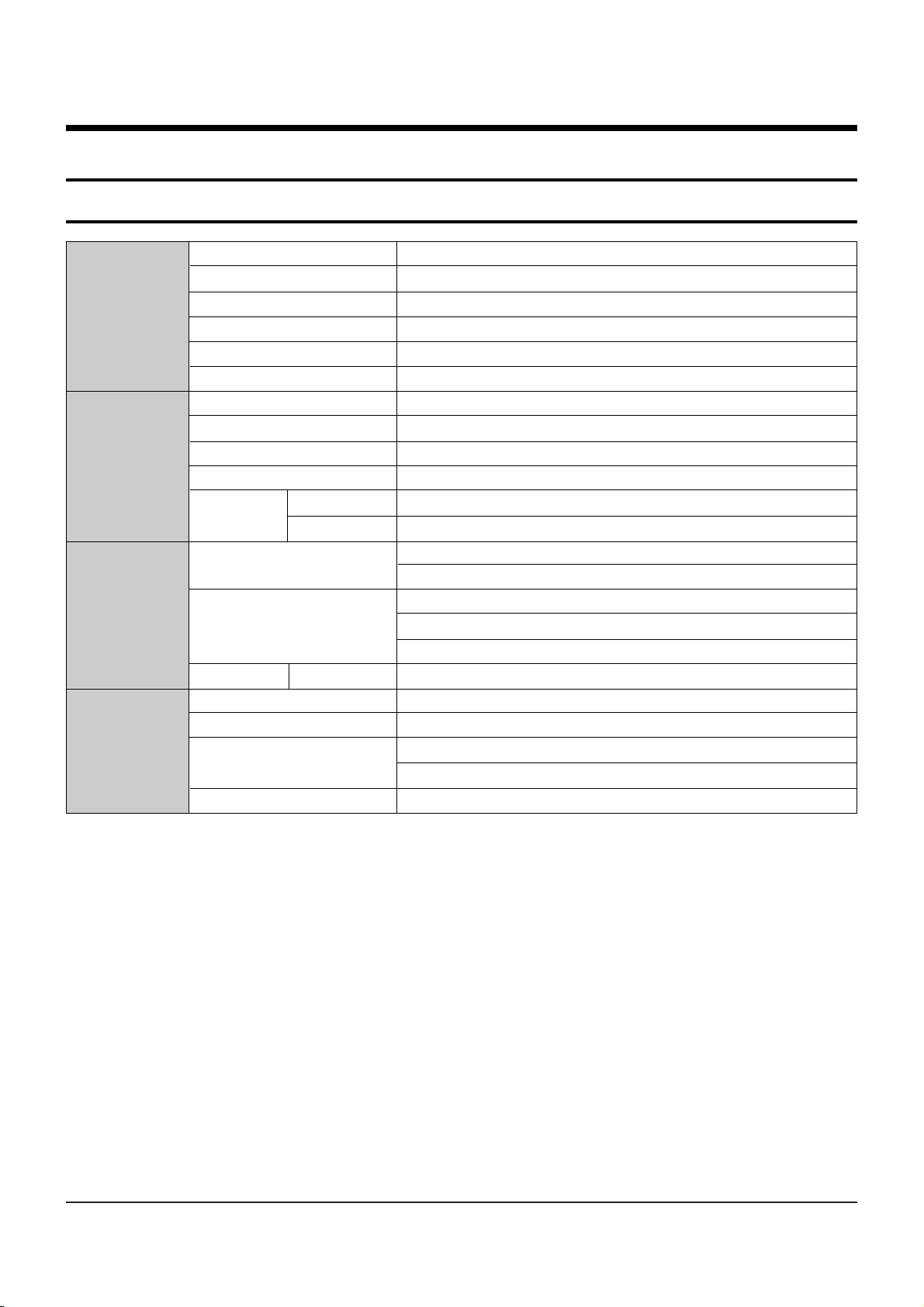
Power requirements AC 220~240V ,50Hz
Power consumption 2.7Watts (Tandby Power), 35Watts (Recording & Playback Simultaneously)
General
Weight 3.9 Kg
Dimensions 430mm(W) x 300mm(D) x 59mm(H)
Operating temp +5°C to +35°C
Other conditions Keep level when operating. Less than 75% operating humidity
Video Composite Video : 1.0 V p-p at 75ohm load, sync negative
Audio Max. Audio input level : 2Vrms
DV Input IEEE 1394(4p) compatible jack
Input Receivable Channels PAL B/G, DK, I
Scart Jack
AV1 (Scart TV) Video : Composite, Audio : analogue
AV2 (Scart Ext) Video : Composite, RGB Audio : analogue
Audio
Analogue output jacks X 2
Optical/coaxial digital audio output
Composite Video : Video output jack X 1
Output
Video S-Video output X 1 (Y: 1.0Vp-p, C:0.286Vp-p at 75 ohm load)
Component output X 1 (Y: 1.0Vp-p ,Pb:0.70Vp-p, Pr:0.70Vp-p at 75ohm load)
Scart Jack AV1 (Scart TV) Video : Composite, RGB Audio : analogue
Picture compression format MPEG-II
Audio compression format Dolby digital 2ch/256kbps, MPEG-II
Recording
Recording Quality
XP (about 8.5 Mbps), SP (about 4.5 Mbps), LP (about 2.5 Mbps),
EP (about 1.6 Mbps or about 1.2 Mbps), FR (about 1.2 Mbps to 8Mbps)
Audio frequency characteristics 20 Hz ~ 20 KHz
2. Product Specification
2-1 Product Specification (DVD-HR730A, DVD-HR734A Europe)
Product Specification
2-2 Samsung Electronics
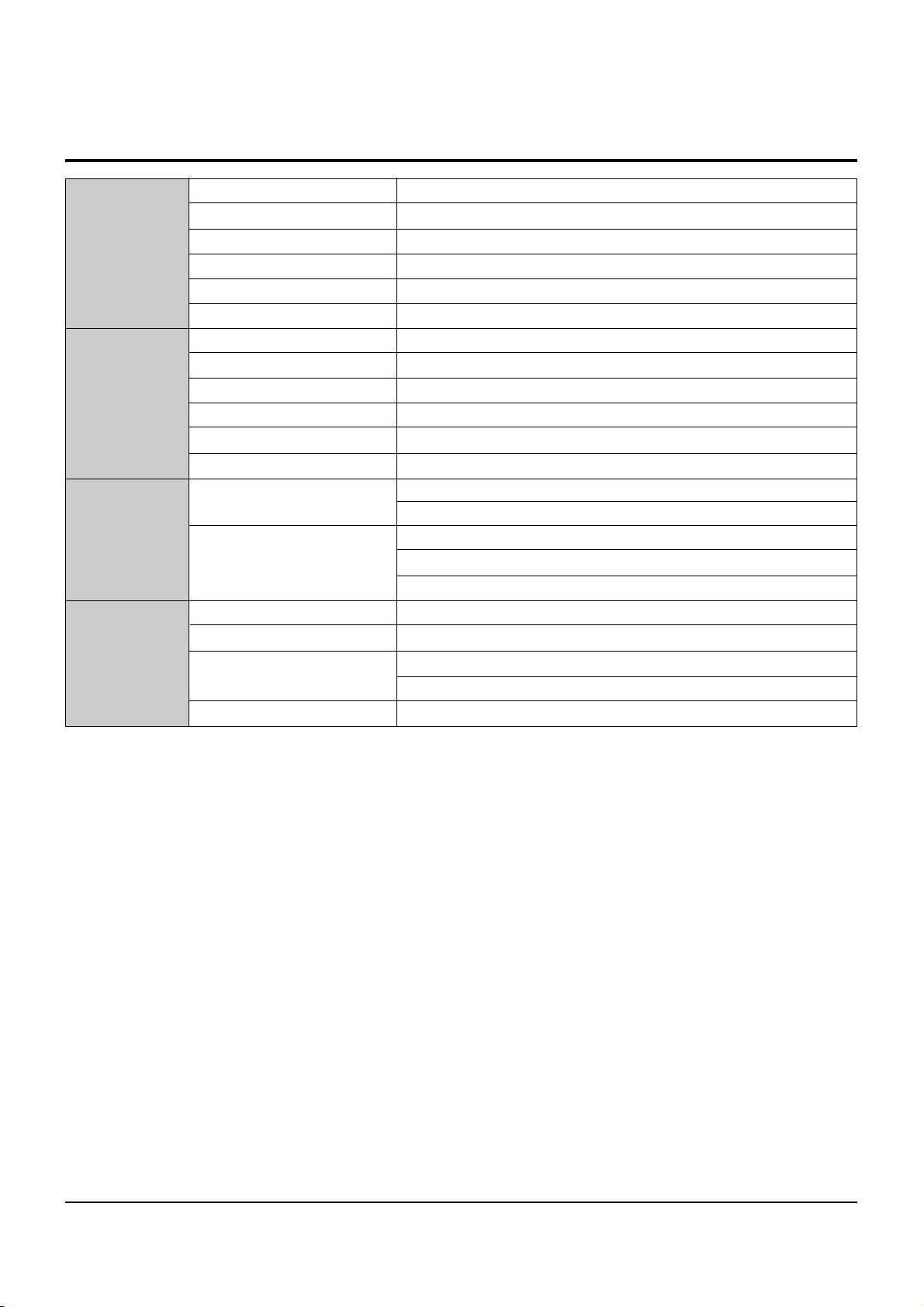
Power requirements AC 220~240V ,50Hz
Power consumption 2.7Watts (Tandby Power), 35Watts (Recording & Playback Simultaneously)
General
Weight 3.9 Kg
Dimensions 430mm(W) x 300mm(D) x 59mm(H)
Operating temp +5°C to +35°C
Other conditions Keep level when operating. Less than 75% operating humidity
Video Composite Video : 1.0 V p-p at 75ohm load, sync negative
Audio Max. Audio input level : 2Vrms
DV Input IEEE 1394(4p) compatible jack
Input Receivable Channels PAL B/G, B/B
AV1 (Rear) Video : Composite, S-Video Audio : analogue
AV2 (Front) Video : Composite Audio : analogue
Audio
Analogue output jacks X 2
Optical/coaxial digital audio output
Output
Composite Video : Video output jack X 1
Video S-Video output X 1 (Y: 1.0Vp-p, C:0.286Vp-p at 75 ohm load)
Component output X 1 (Y: 1.0Vp-p ,Pb:0.70Vp-p, Pr:0.70Vp-p at 75ohm load)
Picture compression format MPEG-II
Audio compression format Dolby digital 2ch/256kbps, MPEG-II
Recording
Recording Quality
XP (about 8.5 Mbps), SP (about 4.5 Mbps), LP (about 2.5 Mbps),
EP (about 1.6 Mbps or about 1.2 Mbps), FR (about 1.2 Mbps to 8Mbps)
Audio frequency characteristics 20 Hz ~ 20 KHz
2-2 Product Specification (DVD-HR730A, DVD-HR732A, DVD-HR734A Asia)
Product Specification
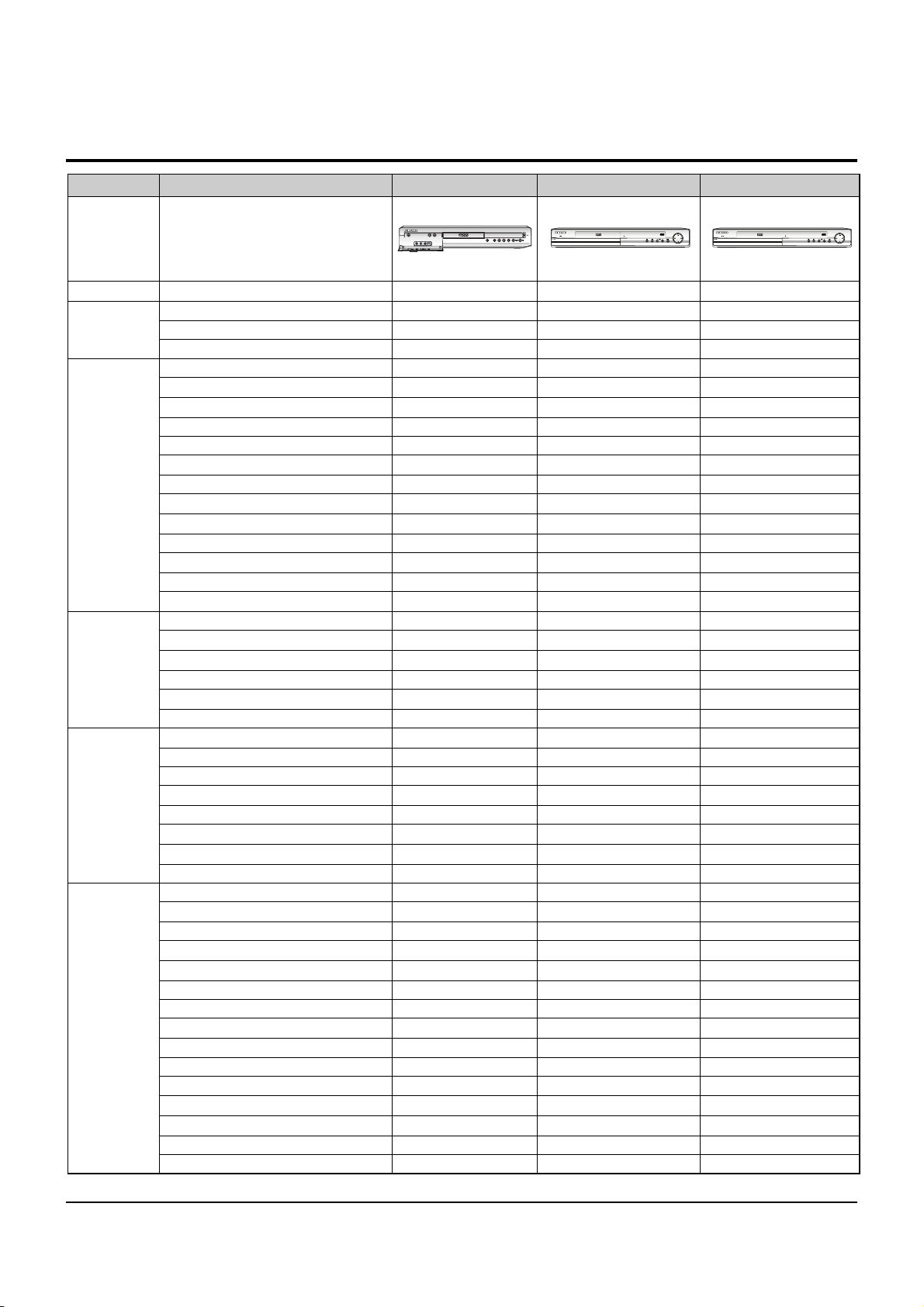
Samsung Electronics 2-3
General Model Name DVD-HR720
DVD-HR730A/HR734A(Europe)
DVD-HR730A/HR732A/HR734A(Asia)
Info Function Standard Standard Standard
COLOR SYSTEM PAL PAL PAL
SYSTEM BROADCAST - I, B/G, D/K, L/L’ I, B/G, D/K, L/L’ B/B, B/G
AUTO CLOCK O O DVD-RAM O - DVD-R O O O
DVD-RW O O O
VIDEO MPEG-2 MPEG-2 MPEG-2
AUDIO 2ch 2ch 2ch
RECORDER DVD-RAM/-R(4.7GB) O - FUNCTION HDD 80GB 80GB 80GB
Flexible Recording O O O
OTR O O O
Time Slip O - O
Video Plus+/Show View/G-Code Video Plus+/Show View - -
Quick Dubbing O O O
EPG(Gemstar) - - -
IR Blaster - - -
Play List O O O
SUB Auto Chaptering O O O
FUNCTION JPEG Browser with BG music O O O
DV Input O O O
10in2 Memory Slot - - -
DVD-RAM/-R/-RW O/O/(O) -/O/(O) O/O/(O)
DVD-Video/VCD/CD-DA O/-/O O/O/- O/O/-
CD-R/RW O/O O/O O/O
PLAYBACK Music CD O O O
FUNCTION MPEG4/Divx O O O
Multi Memory Card - - -
Progressive Scan Output O O O
Upscaling(720P/1080i) O O O
Video / Audio 21pin (on the rear) Yes (AV1) Yes (AV1) -
Sat. 21 pin (on the rear) with RGB Yes (AV2) Yes (AV2) -
Video/Audio in RCA Jack (on the front ) Yes (AV3) Yes (AV3) Yes (AV2)
Video/Audio in RCA Jack (on the rear) - - Yes (AV1)
Video/Audio out RCA Jack (on the rear) Yes x 1 Yes x 1 Yes
Additional Audio output (on the rear) Yes x 1 Yes x 1 Yes
Aerial In / Ant.- out (on the rear) Yes Yes Yes
IN/OUT RGB Output 21 pin Yes (SCART-1) X 1 Yes (SCART-1) X 1 -
Coaxial Digital Audio output Yes x 1 Yes x 1 Yes x 1
Optical Digital Audio output Yes x 1 Yes x 1 Yes x 1
S-Video output (on the rear) Yes x 1 Yes x 1 Yes x 1
S-Video input (on the front) - - -
S-Video input (on the rear) - - Yes
DV input (on the front) Yes Yes Yes
Component VIdeo Output Yes Yes Yes
2-3 Chassis Product Specification

Product Specification
2-4 Samsung Electronics
2-4 Option Product Specification
Description Fig Description Parts No Remark
Remote
Control
Batteries for
Remote Control
AK59-00053H
4301-001035
Model Standard of
DVD-HR730A/XEF
Model Standard of
DVD-HR730A/XEF
S.N.A
Model Standard of
DVD-HR730A/XEF
Model Standard of
DVD-HR730A/XEF
S.N.A
Model Standard of
DVD-HR730A/XEF
Model Standard of
DVD-HR730A/XEF
-
-
AC39-42001R
AC39-00018A
User’s Manual
Quick Guide
Video/Audio
Cable
RF Cable
Samsung Electronics
3-1
3. Software Update
3-1 Drive Firmware Update
3-1-1 Introduction
When you can not record and play on specific recording media (especially on newly available DVD-RW or DVD-R).
3-1-2 How to make an update disc
• Write the downloaded file onto a blank CD-R or CD-RW disc, using the following settings :
1) Download the software update file from the samsung internet site. (http://europe.samsungportal.com)
2) Write the file to disc using the CD-RW of your computer.
• Recommended Application Program
- Nero Burning / Easy CD Creator ..etc
• Option
- Extension name : “*.SMD”
- Multisession : No Multisession
- File name lenght : Max. of 11 = 8 + 3
- Format : Mode 1
- Character set : ISO 9660 or Joliet Format
- CD Close & Dise at once
N O T E
Very important : please read the notice below before updating your unit.
The following events may interrupt the update process and MAY RESULT IN PERMANENT DAMAGE TO THE UNIT WHILE UPDATING
! Unplugging the power cord.
@ Power Outage.
# Dirt or Scratches on the disc.
$ Opening a disc tray during processing.
WARNING

3-2
Software Update
Samsung Electronics
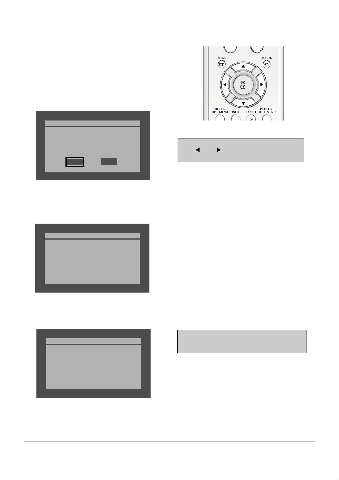
Fig. 3-2
* If you don’t see the message above, try another disc. Generally, this is caused by disc quality and by disc creating problem.
4) Press the OK button on the remote control (Fig. 3-1).
Fig.3-3
5) It takes about 1~2 minutes to complete the update.
The message below will be displayed in the screen after update is completed and the tray will open automatically.
Fig. 3-4
6) After removing the update disc, turn off the unit with power button.
Turn on the power again the tray will then close.
The drive firmware is now complete.
Drive Update
Do you want to update drive-firmware?
Version: Xx.X.HR730A -> XX.X.HR730A
No
Yes
Atfer checking old and new version, select “Yes” or “No”
with “ ” or “ ” on the remote control.
* The Version is indicated by “XX.X modelname”
You will see “LOAD” on FLT Display.
Drive Update
Now, processing...
please, do not turn off the power.
Drive Update
Drive firmware is successfully
updated.
Fig. 3-5
1) Press OPEN/CLOSE to open the disc tray.
2) Insert the update CD-R disc with the software update, label
facing up.
3) Press OPEN/CLOSE to close the disc tray.
* It takes about 1~2 minites before the mesage below appears.
Fig. 3-1 Remote Control

Software Update
3-3
Samsung Electronics
3-2 Flash Update
3-2-1 Introduction
When you encounter the problem which is not related in drive firmware necessity.
3-2-2 How to make an update disc
Write the downloaded file onto a blank CD-R or CD-RW disc, using the following settings :
1) Download the software update file from the samsung internet site. (http://europe.samsungportal.com)
2) Write the file to disc using the CD-RW of your computer.
• Recommended Application Program
- Nero Burning / Easy CD Creator ..etc
• Option
- Multisession : No Multisession
- CD close & disc at once
- ISO 9660 or joliet format
- Extension name : “*.RUF”
• In order to increase disc playability, add a dummy file (over 100MB) together with the latest program.
(The dummy file can be any kind of file except MP3 file etc which can be played in the unit and we recommend to use a file whose
extension name as “*.dmy”, which can be changed from original one.)
N O T E
Very important : please read the notice below before updating your unit.
The followong events may interrupt the update process and MAY RESULT IN PERMANENT DAMAGE TO THE UNIT WHILE UPDATING
! Unplugging the power cord.
@ Power Outage.
# Dirt or Scratches on the disc.
$ Opening a disc tray during processing.
WARNING
3-4
Software Update
Samsung Electronics
Fig. 3-7
* If you don’t see the message above, try another disc.
Generally, this is caused by disc quality and by disc creating problem.
4) Press the OK button on the remote control (Fig. 3-6).
Fig. 3-8
5) It takes about 5 minutes to complete the update.
The message below will be displayed in the screen after update is completed and the tray will open automatically.
Fig. 3-9
6) After removing the update disc, turn off the unit with power button.
Turn on the power again and the tray will then close.
The Flash update is now complete.
* If the message to the left isn’t displayed after 10minutes
and the unit is no longer functioning properly, contact a
samsung authorized service center.
Atfer checking old and new version, select “Yes” or “No”
with “ ” or “ ” on the remote control.
* The Version is indicated by “YYMMDD.xx modelname”
Flash Update
Do you want to update flash memory?
Version : YYMMDD.xx.HR730A
-> YYMMDD.xx.HR730A
No
Yes
Flash Update
Now, Processing...
Plase. do not turn off the power.
Flash Update
Flash memory is successfully
updated.
1) Press OPEN/CLOSE to open the disc tray.
2) Insert the update CD-R disc with the software update, label
facing up.
3) Press OPEN/CLOSE to close the disc tray.
Fig. 3-6 Remote Control

Samsung Electronics
4-1
4. Disassembly and Reassembly
4-1 Cabinet and PCB
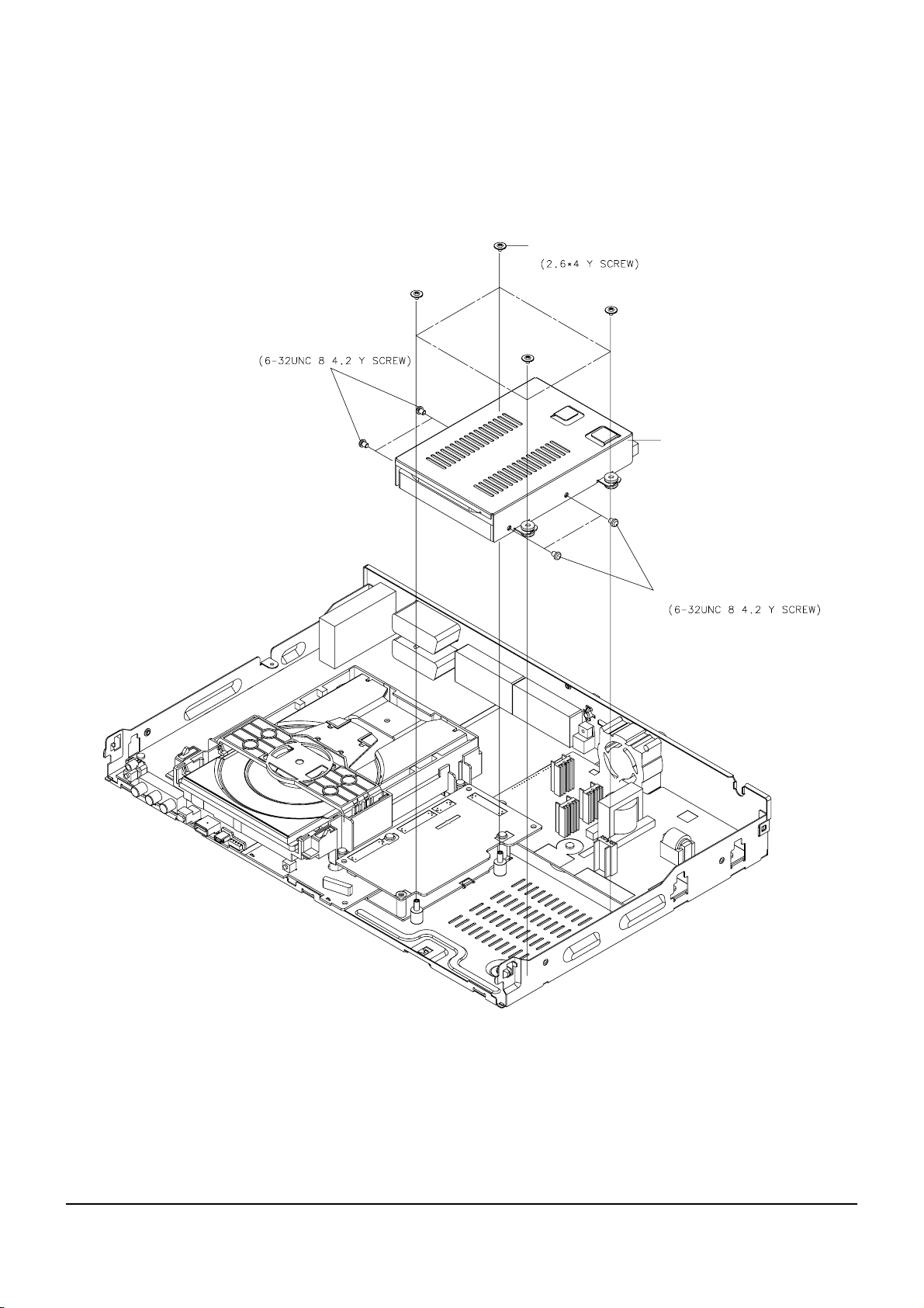
4-1-1 Top Cabinet Removal
1) Remove 5 Screws Œ, ´.
2) Lift up the Top Cabinet in direction of arrow.
Fig. 4-1 Top Cabinet Removal
Note : Reassembly in reverse order.
Π3 SCREWS
´ 2 SCREWS
4-2
Samsung Electronics
Disassembly and Reaasembly
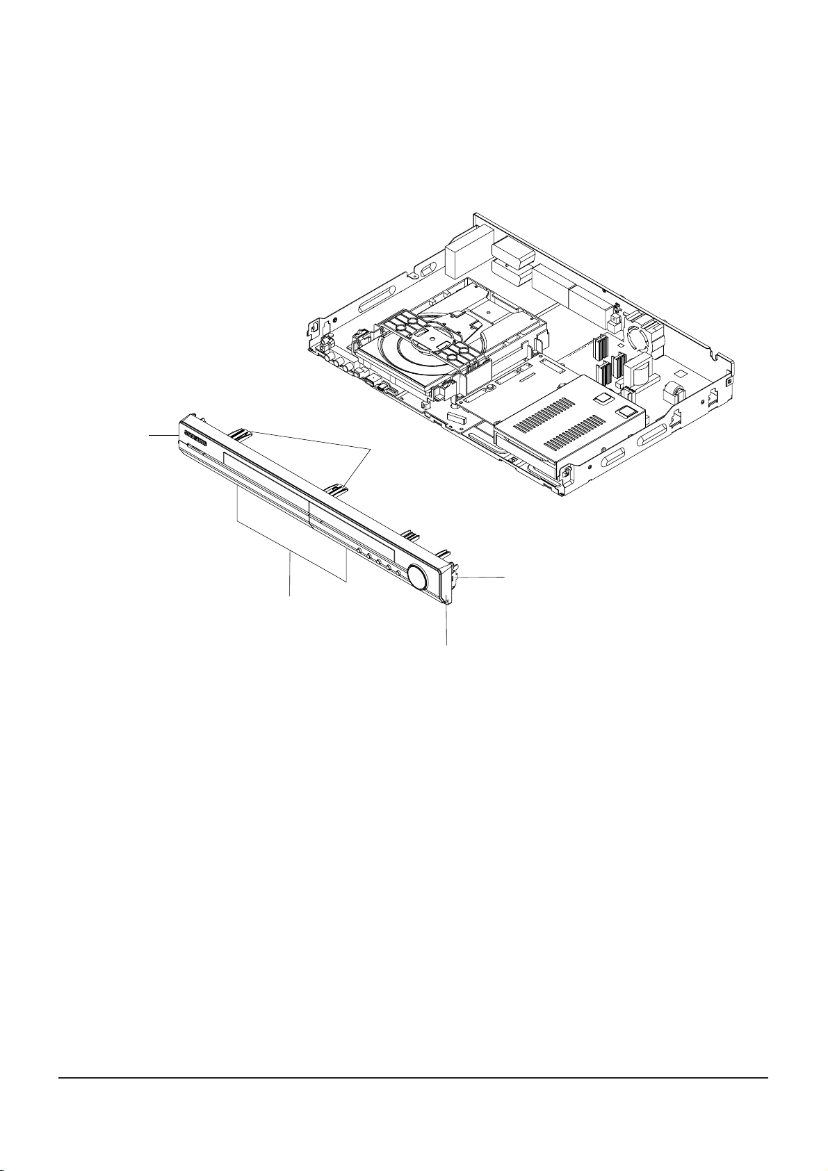
Fig. 4-2 Ass’y Front-Cabinet Removal
4-1-2 Ass’y Front-Cabinet Removal
1) Release 6 Hooks Œ, ´, ˇ, ¨ and Ass’y Front-Cabinet ˆ.
Π1 HOOK
¨ 2 HOOKS
´ 1 HOOK
ˇ 2 HOOKS
ˆ ASS'Y FRONT-CABINET
Disassembly and Reaasembly
Samsung Electronics
4-3
4-1-3 Hard Disk Removal
1) Remove 8 Screws Œ, ´, ˇ from the Hard Disk and lift it up.
Fig. 4-3 Hard Disk Removal
´ 2 SCREWS
Π4 SCREWS
HARD DISK
ˇ 2 SCREWS
4-4
Samsung Electronics
Disassembly and Reaasembly
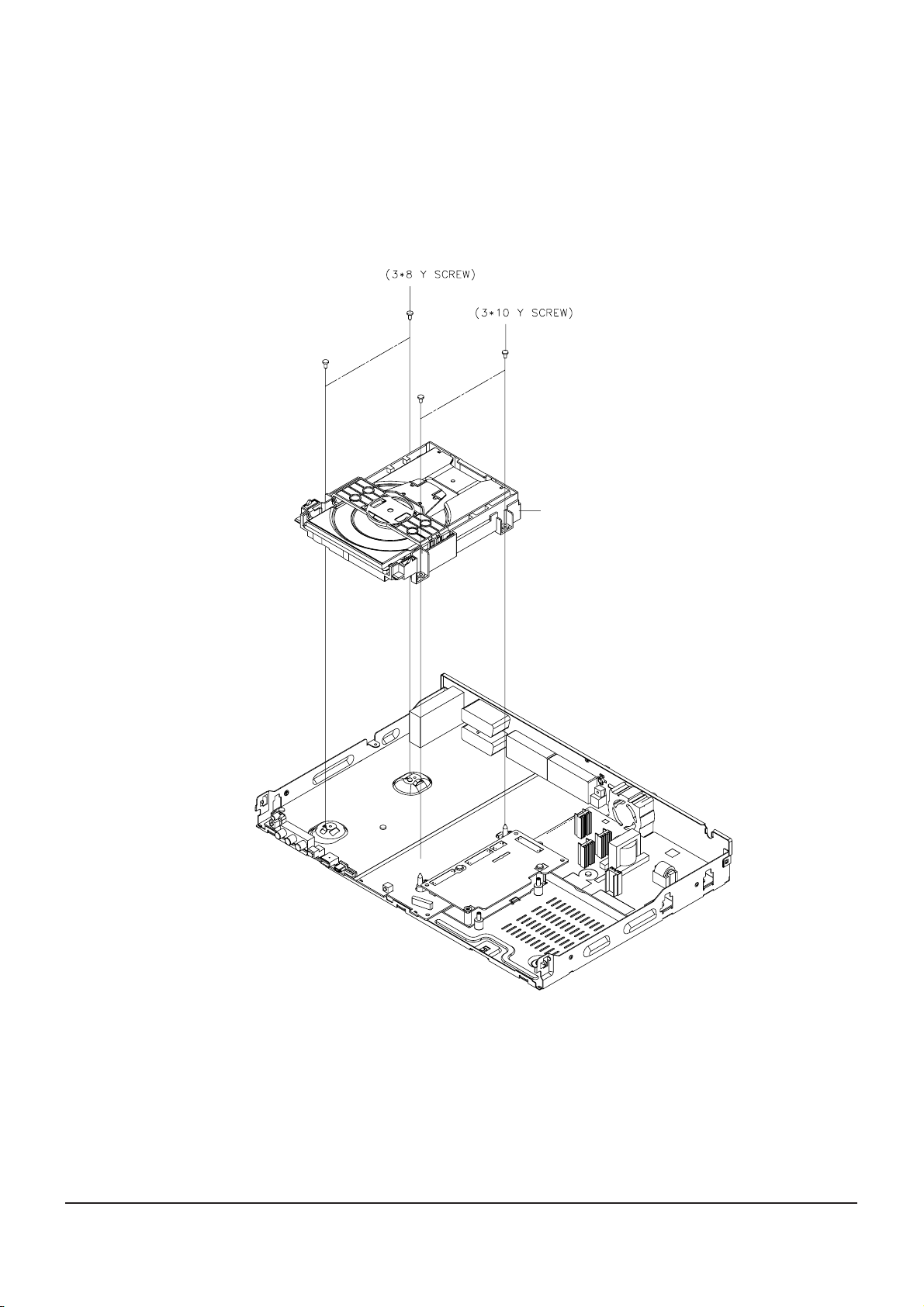
Fig. 4-4 Ass’y Deck Removal
4-1-4 Ass’y Deck Removal
1) Remove 4 Screws Œ, ´ from the Ass’y Deck and lift it up.
Π2 SCREWS
´ 2 SCREWS
Assy Deck
Disassembly and Reaasembly
Samsung Electronics
4-5
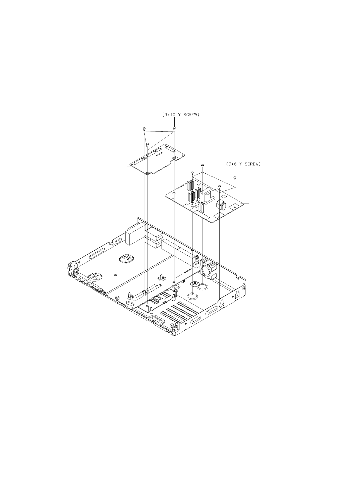
Fig. 4-5 Main PCB and S.M.P.S. PCB Removal
4-1-5 Main PCB and S.M.P.S. PCB Removal
1) Remove 3 Screws Œfrom the Main PCB ´ and lift it up.
2) Remove 4 Screws ˇ from the S.M.P.S. PCB ¨ and lift it up.
Π3 SCREWS
´ MAIN PCB
ˇ 4 SCREWS
¨ SMPS PCB

4-6
Samsung Electronics
Disassembly and Reaasembly
4-1-5 Jack PCB Removal
1) Remove 4 Screws Œ from the Jack PCB ´ and lift it up.
Fig. 4-5 Jack PCB Removal
Π4 SCREWS
´ JACK PCB

Disassembly and Reaasembly
Samsung Electronics
4-7
4-1-6 DC FAN Removal
1) Remove 2 Screws Œ, from the DC Fan ´ and lift it up.
Fig. 4-6 DC FAN Removal
´ DC FAN
Π2 SCREWS
4-8
Samsung Electronics
Disassembly and Reaasembly
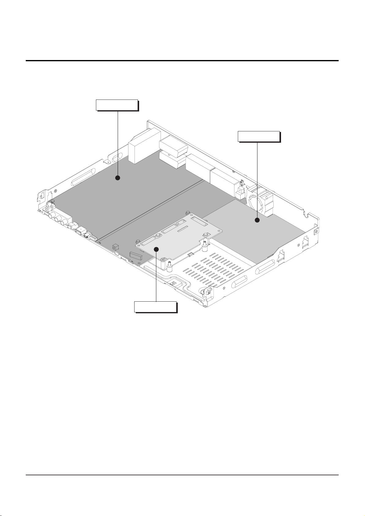
4-2 PCB Location
Fig. 4-7 PCB Location
JACK PCB
S.M.P.S. PCB
MAIN PCB
Samsung Electronics 5-1
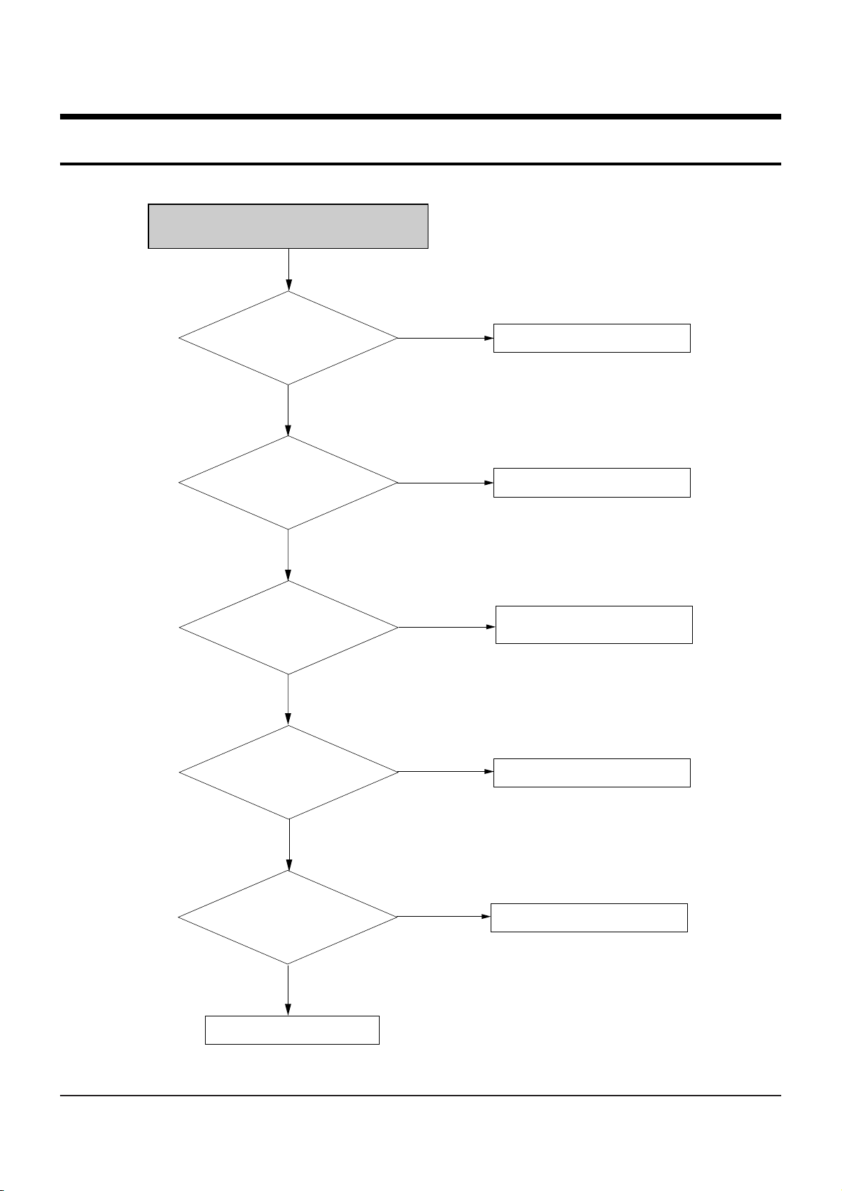
5. Troubleshooting
NO Power Detected
(Stand by LED OFF)
PAFT1 is normal?
Change fuse
Change AVFP1 LED Module
Check 2st voltage
Replace QISO1
Check feed back ICISO1
Change short circuited or
opened parts
6pin of AIC1 in the
function key is normal?
PVDLL1, PSDZ1
PFZZ1, PVZL1 SHOR and OPEN
Are normal?
Is there voitage at
Collector of
QISO1
Operation of QISO1 is
Normal?
Yes
No
Yes
Yes
Yes
Yes
No
No
No
No
 Loading...