

Samsung Dvd-829 Disassemble
Samsung Electronics
5-1
5. Disassembly and Reassembly
5-1 Cabinet and PCB
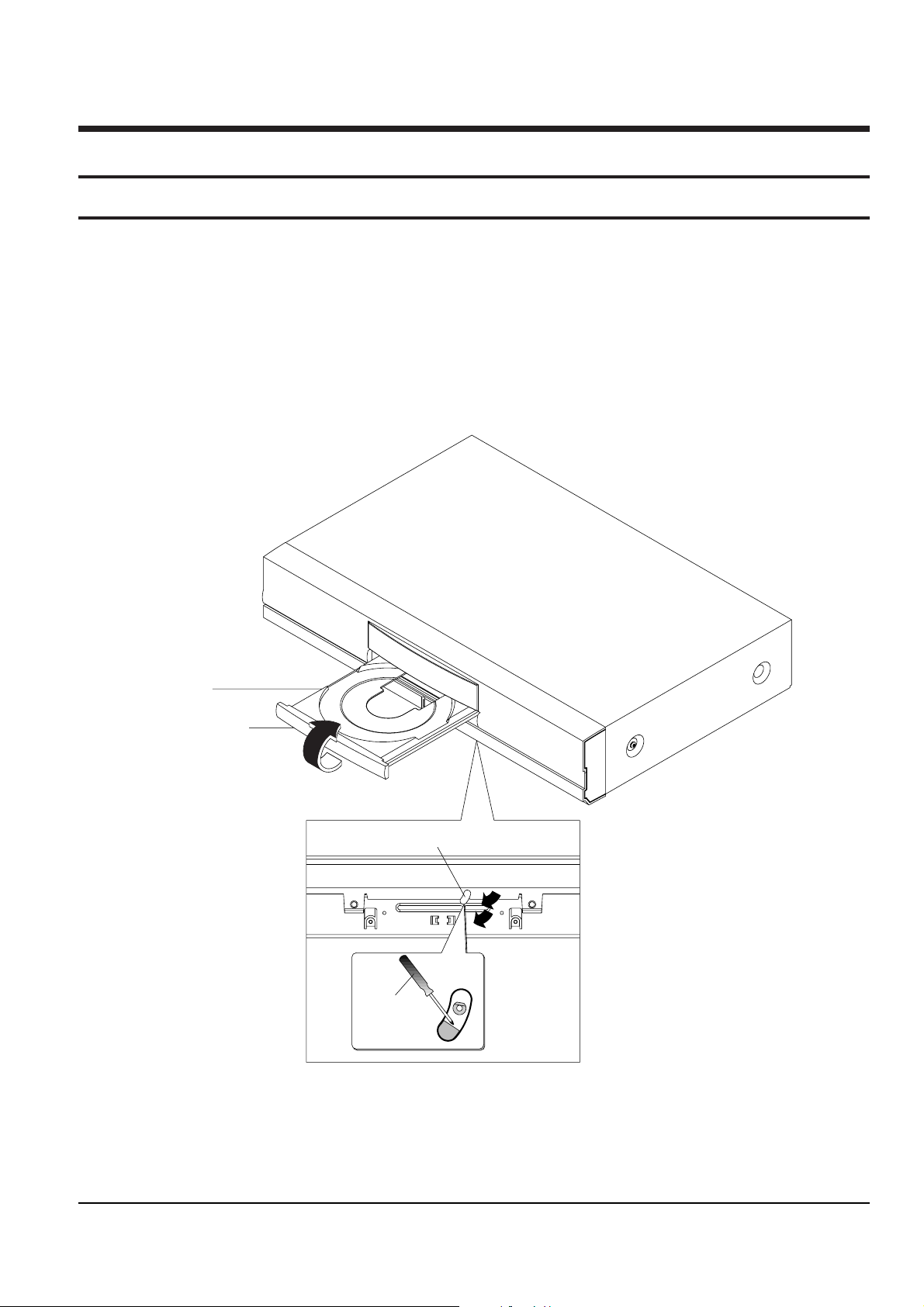
5-1-1 Door-Tray Removal
1) Supply power and open Tray Œ.
2) Disassemble the Door-Tray ´ in direction of arrow ÒAÓ.
3) Close Tray Πand power off.
Note : If Tray Œ doesnÕt open, insert a Screw driver ¨ into the Emergency hole ˇ(as shown in detailed draw-
ing) and then turn it in the direction of arrow ÒBÓ. Open Tray manually.
ˇ EMERGENCY HOLE
<Bottom View>
ΠTRAY
´ DOOR-TRAY
"A"
"B"
¨ SCREW
DRIVER
Fig. 5-1 Door-Tray Removal
5-2
Samsung Electronics
Disassembly and Reaasembly
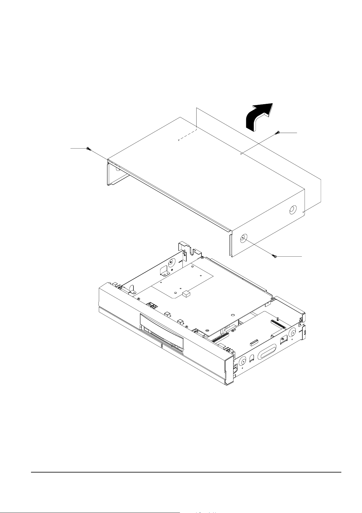
5-1-2 Top Cabinet Removal
1) Remove 3 Screws Πon the back Top Cabinet.
2) Remove 2 Screws ´, ˇ on the left and right side.
3) Lift up the Top Cabinet in direction of arrow.
Π3 SCREWS
´ 1 SCREW
ˇ 1 SCREW
Fig. 5-2 Top Cabinet Removal

Disassembly and Reaasembly
Samsung Electronics
5-3
Π2 SCREWS
Ø 4 TABS
´ CN18
ˇ
CN15
∏ 2 TABS
” TAB
’ TAB
˝ ASS'Y FRONT-PANEL
¨ KCN2
Ô KNOB-VOLUME
ˆ KCN1
KNOB-JOG
Ò KNOB-SHUTTLE
Ú 2 SCREWS
Æ KARAOKE/POWER PCB
ı 3 SCREWS
˜ 2 TABS
¯ PLAY PCB
Fig. 5-3 Ass’y Front-Panel, Power PCB, Mic PCB, Karaoke PCB, Play PCB Removal
5-1-3 Ass’y Front-Panel, Karaoke/Power PCB, Play PCB Removal
1) Remove 2 Screws Œ and disconnect CN18 ´ and CN15 ˇ from Jack PCB and KCN2 ¨, KCN1 ˆ from
Karaoke/Power PCB.
2) Release 4 Tabs Ø, 2 Tabs ∏, Tab ”, ’ and disassemble the AssÕy Front Panel ˝.
3) Remove Knob-Volume Ô.
4) Remove Knob-Jog , Knob-Shuttle Ò.
5) Remove 2 Screws Ú and disassemble the Karaoke/Power PCB Æ.
6) Remove 3 Screws ı and release 2 Tabs ˜ and disassemble the Play PCB ¯.
5-4
Samsung Electronics
Disassembly and Reaasembly
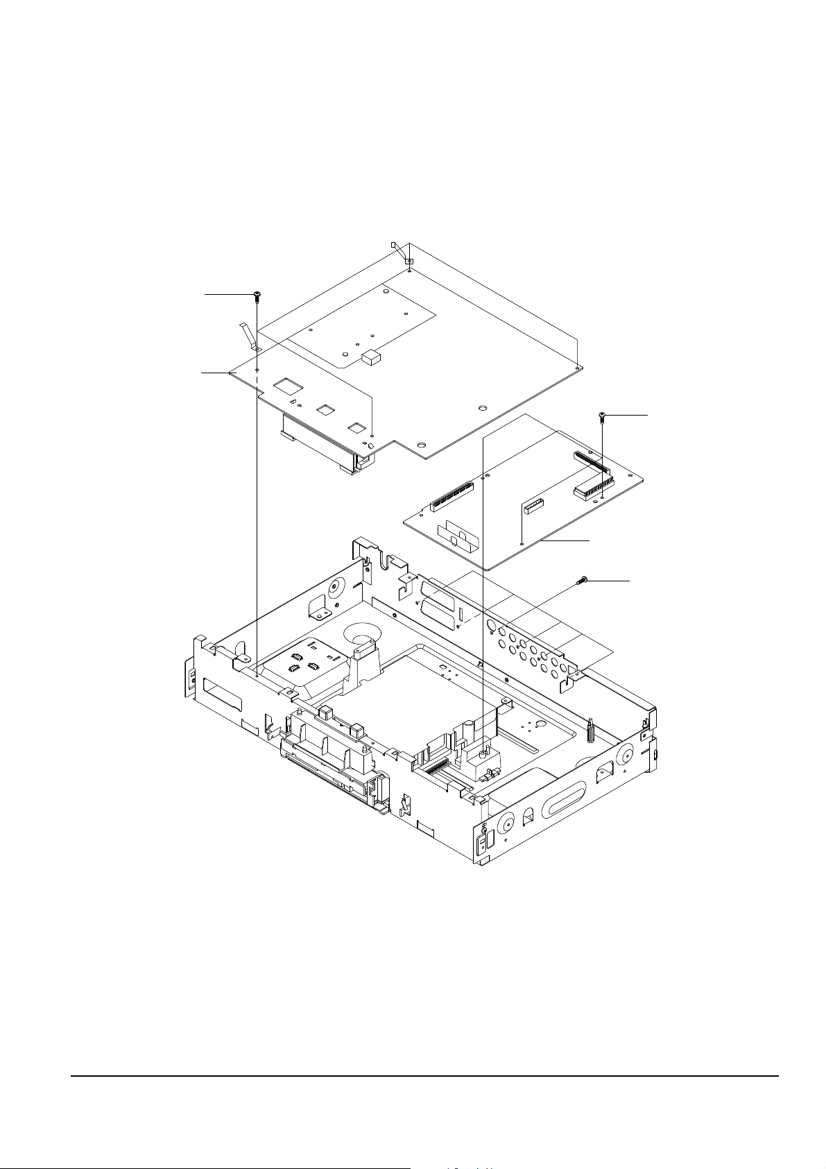
Π4 SCREWS
ˇ JACK PCB
ˆ MAIN PCB
´ 6 SCREWS
¨ 3 SCREWS
Fig. 5-4 Main PCB, Jack PCB Removal (DVD-929K)
5-1-4 Main PCB, Jack PCB Removal (DVD-929K)
1) Remove 4 Screws Œ and 6 Screws ´.
2) Lift up the Jack PCB ˇ.
3) Remove 3 Screws ¨ and lift up the Main PCB ˆ.
Disassembly and Reaasembly
Samsung Electronics
5-5
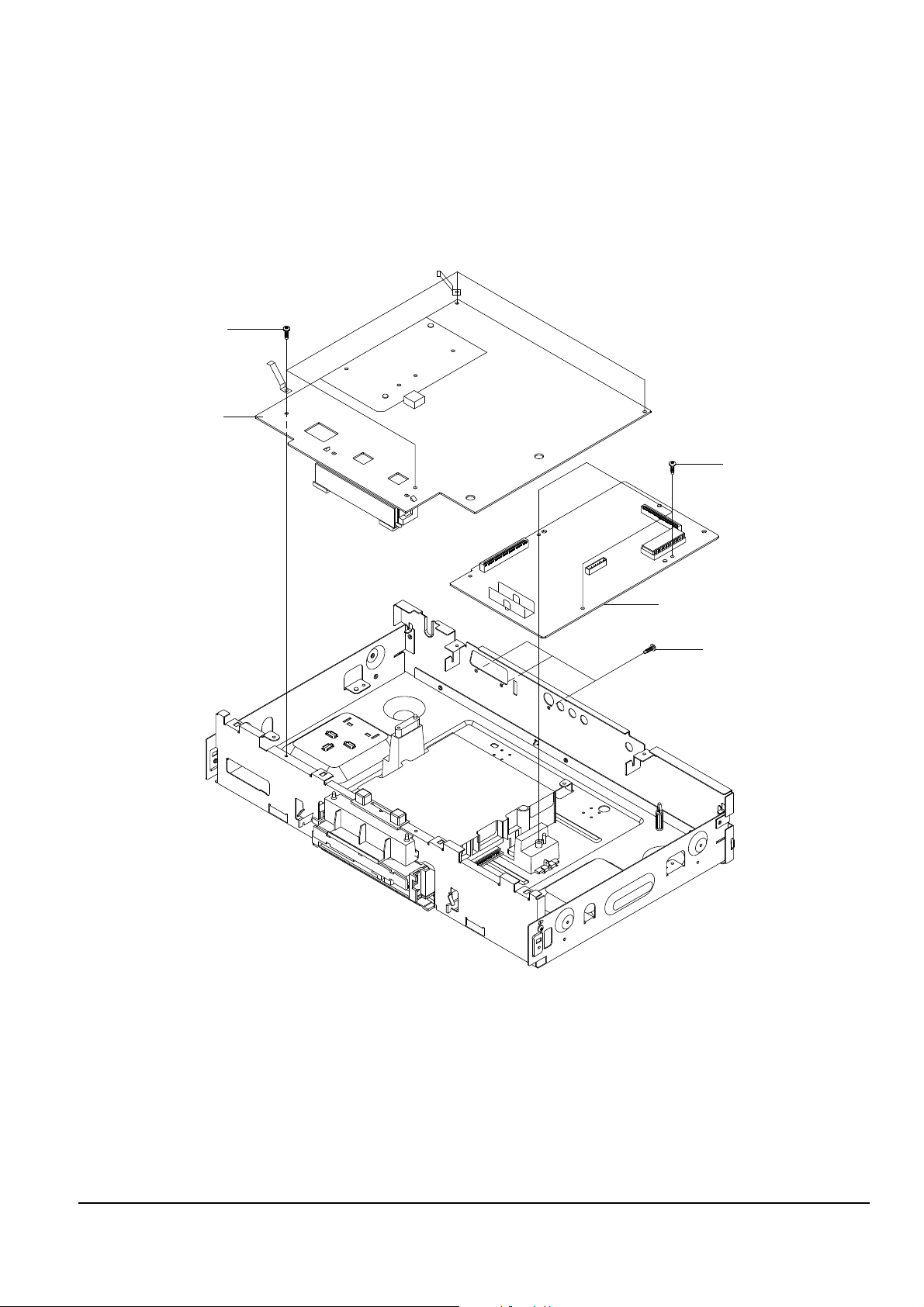
Π4 SCREWS
ˇ JACK PCB
ˆ MAIN PCB
´ 3 SCREWS
¨ 3 SCREWS
Fig. 5-5 Main PCB, Jack PCB Removal (DVD-829K)
5-1-5 Main PCB, Jack PCB Removal (DVD-829K)
1) Remove 4 Screws Œ and 3 Screw ´.
2) Lift up the Jack PCB ˇ.
3) Remove 3 Screws ¨ and lift up the Main PCB ˆ.
 Loading...