

Samsung DVD-808 Disassemble
Samsung Electronics 5-1
5. Disassembly and Reassembly
5-1 Exterior and PCB Disassembly
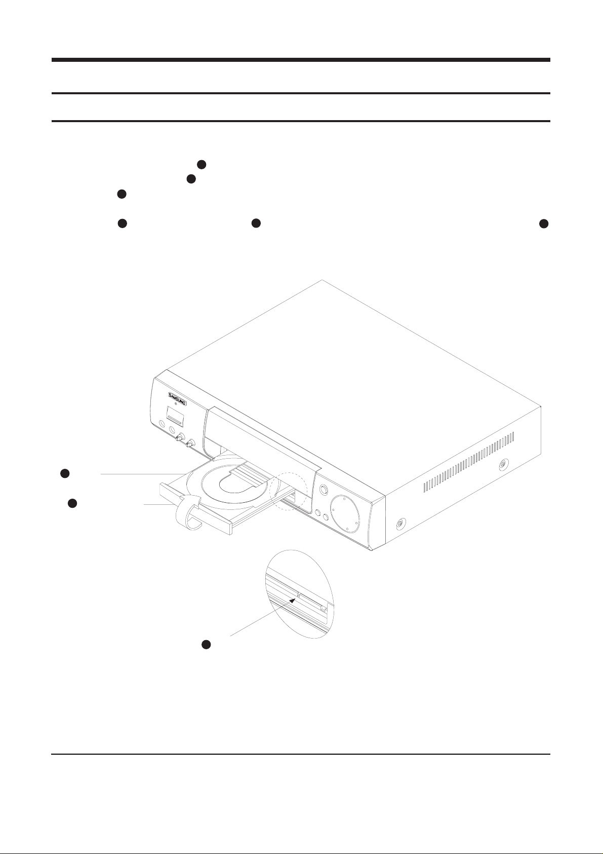
1) Supply power and open Tray .
2) Disassemble the door-tray in direction of arrow.
3) Close Tray and power off.
Note : If Tray doesn’t open, insert a clip into the hole (as shown in detailed drawing), and open Tray
manually.
5-1-1 Door-tray
1
2
1
131
Fig. 5-1
1
TRAY
2
DOOR-TRAY
3
CLIP
70mm
Disassembly and Reassembly
5-2 Samsung Electronics
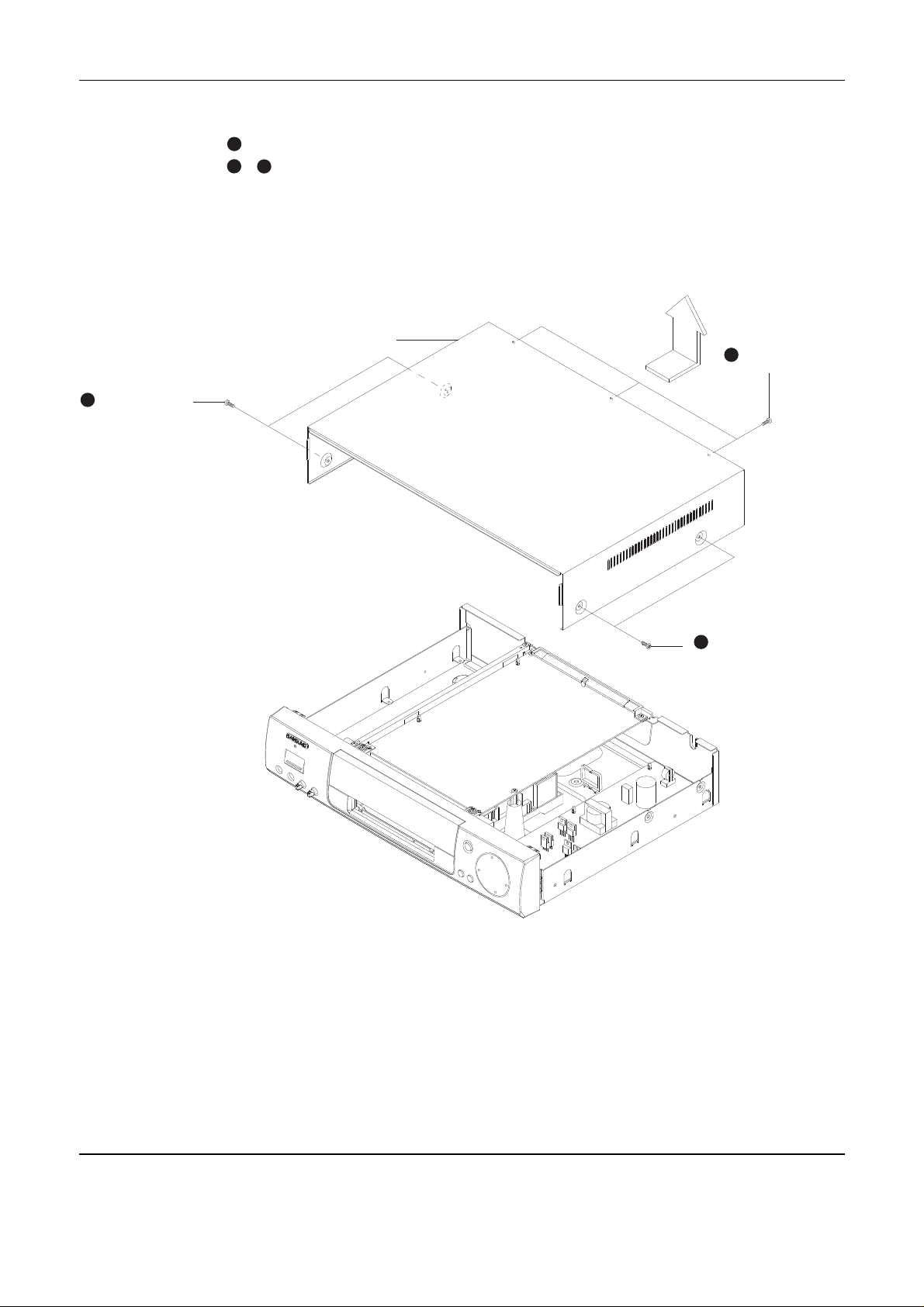
5-1-2 Top cabinet
1. Remove 3 screws on the back panel.
2. Remove 4 screws , on the left and right side.
3. Lift up the top cabinet in direction of arrow.
Fig. 5-2
1
232
CABINET-TOP
2 SCREWS
1
3 SCREWS
3
2 SCREWS
Disassembly and Reassembly
Samsung Electronics 5-3
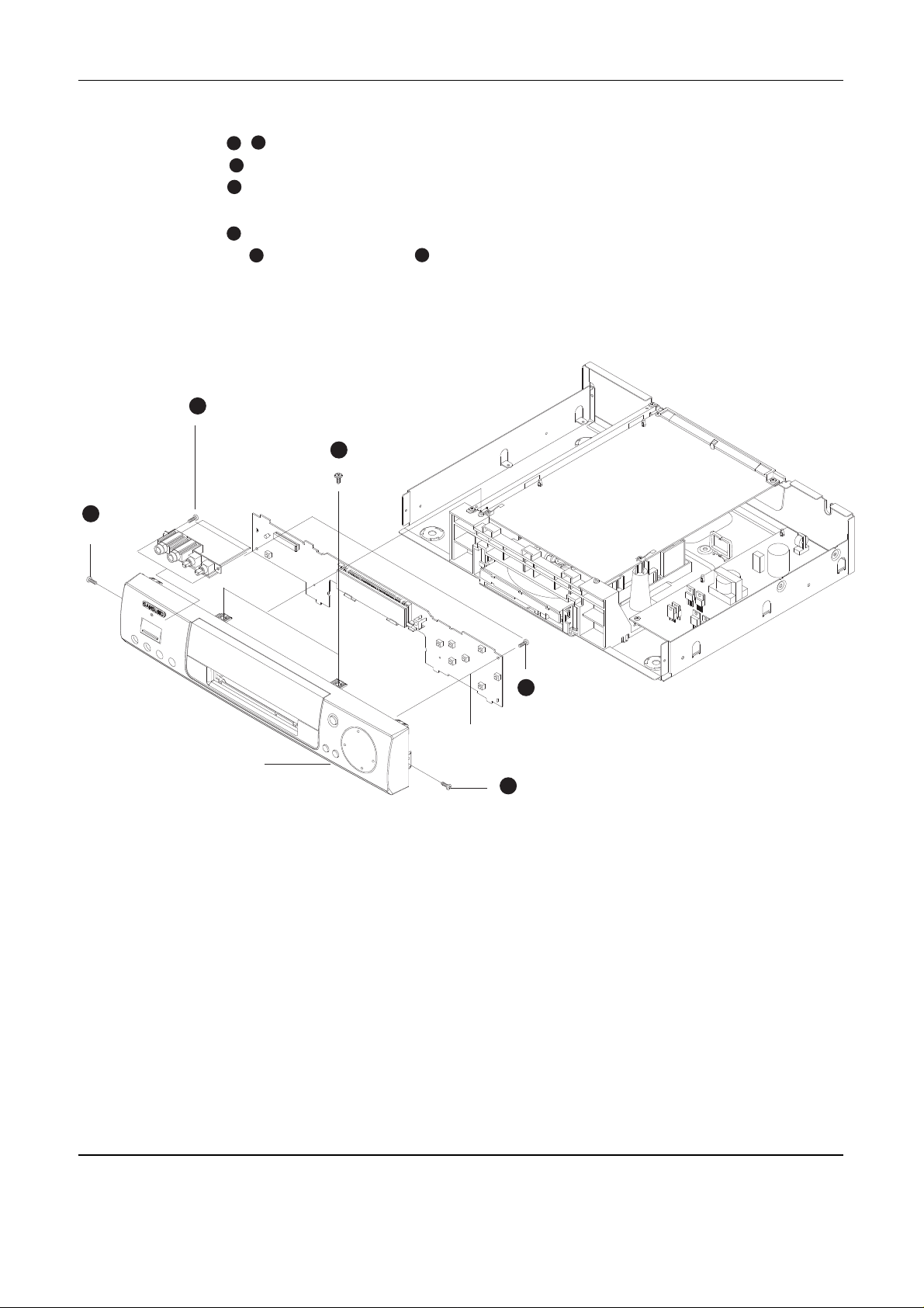
5-1-3 Panel-Front, PCB-Front
1. Remove 2 screws , on the left and right side of panel-front ass’y
2. Remove 2 screws on the bottom of cover-panel ass’y and disassemble the front.
3. Remove 2 screws from PCB-front.
4. Remove 9 hooks to fix PCB-front and disassemble PCB-front.
5. Remove 2 screws on the top of cover-panel ass’y
6. Remove 4 top hooks and 5 bottom hooks and disassemble the cover-panel ass’y.
Fig. 5-3
1
3
4
5
6
7
2
5
1
3
1
2 SCREWS
2 SCREWS
4
2 SCREWS
1 SCREW
1 SCREW
PCB-FRONT
ASSY PANEL-FRONT
Disassembly and Reassembly
5-4 Samsung Electronics
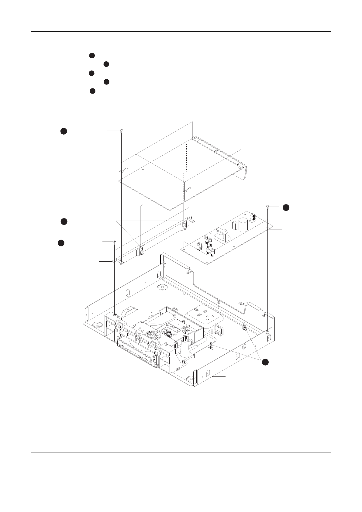
5-1-4 PCB-MAIN, PCB-SMPS
1. Remove 4 screws to fix PCB-MAIN.
2. Remove 2 Holder-PCB inserted in PCB-MAIN and lift up PCB-MAIN.
3. Remove 3 screws from PCB-SMPS.
4. Remove 3 Spacer-PCB inserted in PCB-SMPS and lift up PCB-SMPS.
5. Remove 2 screws to fix BRKT-PCB ass’y.
Fig. 5-4
123
4
5
1
4 SCREWS
3
4 SCREWS
4
SPACRE-PCB
5
2 SCREWS
ASSY BRKT-PCB
PCB-SMPS
ASS’Y BOTTOM
2
HOLDER-PCB
 Loading...