

Samsung DV7700, DV4720 Disassemble
Samsung Electronics
3-1
3. Disassembly
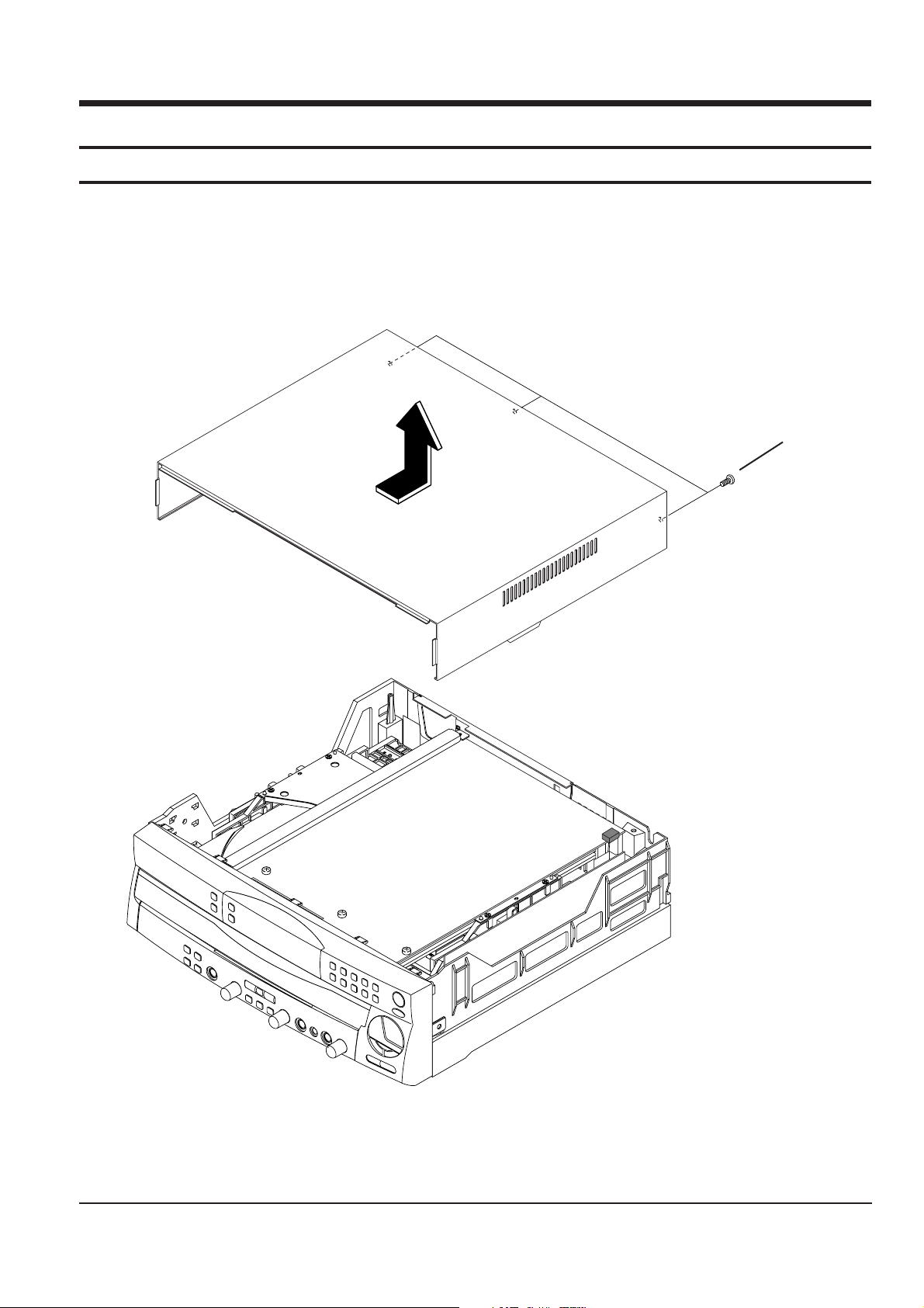
3-1 Disassembling the Top-Cabinet (Fig 1.)
1. Loosen 3 screws ! (3 x 10 black).
2. Push top 10mm backward horizontally, and separate it upward.
Figure 1.
1
!
Samsung Electronics
3-2
1
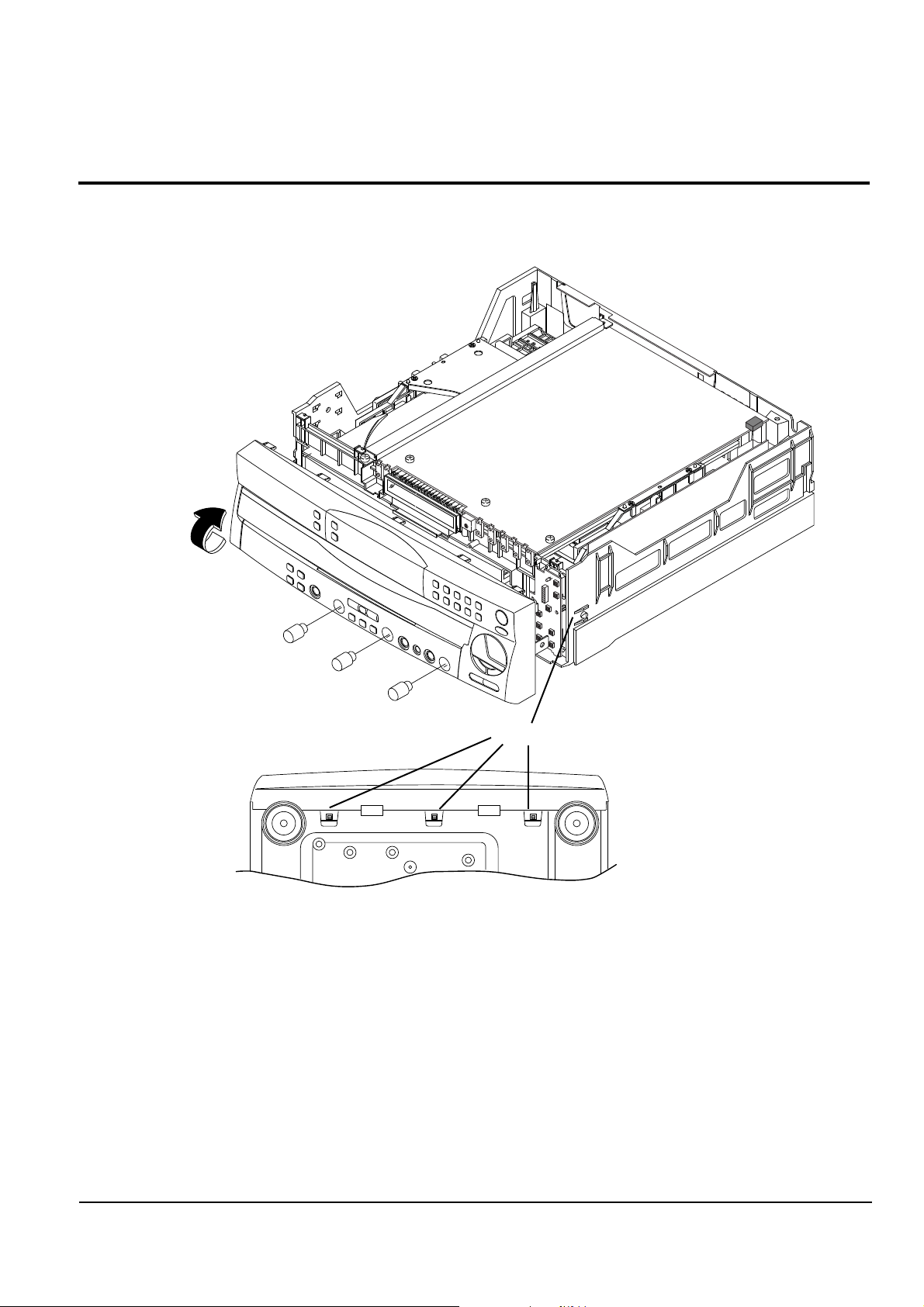
3-2 Disassembling the ass'y front (Fig. 2)
1. Separate ass'y front by pulling it horizontally using 3 knobs volume.
2. Loosen 5 hooks more or less(2 hooks on right and left side, and 3 hooks on the bottom)
3. Seperate ass'y front by turning it to the arrow direction.
Figure 2.
bottom view
knob volume
hook
Disassembly
3-3
1
Samsung Electronics
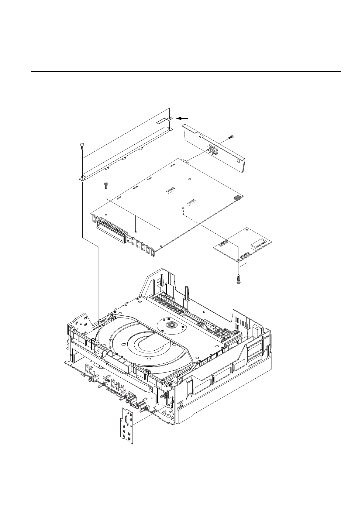
Figure 3.
3-3 Disassembling the Main PCB and VCD PCB (Fig-3)
1. Lossen 6 screws ( 5EA of 3 x 10 yellow, 1EA of 3 x10 black ).
2. After pull out the tray, turn the main PCB to the right side.
3. Separating flexible connected to PCB, and separate it by pulling the part connected 2EA of holder PCB.
4. Separate the BRACKET PCB and COVER REAR.
Cover Rear
Bracket PCB
Bracket PCB/G
Main PCB
Front PCB
Disassembly
 Loading...