

SAMSUNG DIGIMAX I50 Service Manual [EN]

2
CONTENTS
ⅠⅠ..
SSPPEECCIIFFIICCAATTIIOONN
1.SPECIFICATION………………………………………………………………………………………………… 4
2.SYSTEMREQUIREMENTS …………………………………………………………………………………… 6
3.LCDmonitorindicator ……………………………………………………………………………………… 7
4.CONNECTIONDIAGRAM ……………………………………………………………………………………… 9
5.IDENTIFICATIONOFFEATURES …………………………………………………………………………… 10
Ⅱ.INSTALLATION
………………………………………………………………………………………………… 12
Ⅲ.EXPLODEDVIEWANDPARTSLIST
1.MAINASSEMBLY………………………………………………………………………………………………22
2.BODYASSEMBLY ……………………………………………………………………………………………24
3.BARRELASSEMBLY ………………………………………………………………………………………… 26
4.MIDDLECOVERASSEMBLY …………………………………………………………………………………28
5.BACKCOVERASSEMBLY ……………………………………………………………………………………30
6.CRADLEASSEMBLY …………………………………………………………………………………………32
7.PACKINGITEM…………………………………………………………………………………………………34
Ⅳ.ADJUSTMENT
1.DIGITALCAMERASERVICE …………………………………………………………………………………37
2.Tuningitembychangedparts ……………………………………………………………………………43
3.Adjustment ……………………………………………………………………………………………………46
Ⅴ.PATTERNDIAGRAM
1.PARTSARRANGEMENTFOREACHPCBASS’Y
1)MAIN_TOP…………………………………………………………………………………………………56
2)MAIN_BOTTOM……………………………………………………………………………………………57
3)STROBE_TOP ……………………………………………………………………………………………58
4)STROBE_BOT ……………………………………………………………………………………………59
5)MAIN_FPCB………………………………………………………………………………………………60
6)SHUTTER_FPCB …………………………………………………………………………………………61
7)CCD …………………………………………………………………………………………………………62
8)KEY …………………………………………………………………………………………………………63
9)TOP_FPCB ………………………………………………………………………………………………64
10)LENSCAT_FPCB ………………………………………………………………………………………65
11)SUB_FPCB………………………………………………………………………………………………66
12)CRADLE_MAIN_TOP……………………………………………………………………………………67
13)CRADLE_MAIN_BOT……………………………………………………………………………………67
14)CRADLE_SUB_TOP ……………………………………………………………………………………68
15)CRADLE_SUB_BOT ……………………………………………………………………………………68

3
Ⅵ.CIRCUITDIAGRAM
1.BLOCKDIAGRAM………………………………………………………………………………………………69
2.CIRCUITDIAGRAM
1)MAINBLOCKDIAGRAM …………………………………………………………………………………70
2)CCDAFE……………………………………………………………………………………………………71
3)AUDIOCODEC ……………………………………………………………………………………………72
4)CARDFPCBCONNECTOR ………………………………………………………………………………73
5)COACH………………………………………………………………………………………………………74
6)LCDDRIVER ………………………………………………………………………………………………75
7)MOTORDRIVER ……………………………………………………………………………………………76
8)SYSTEMPOWER …………………………………………………………………………………………77
9)SYSTEMMEMORY ………………………………………………………………………………………78
10)SUBPCBCONNECTOR …………………………………………………………………………………79
11)POWERONKEY …………………………………………………………………………………………80
12)MICOM ……………………………………………………………………………………………………81
Ⅶ.TROUBLESHOOTING
1.CheckListforrepairing ……………………………………………………………………………………82
2.POWERONFLOWCHART ……………………………………………………………………………………83
3.Principaltroubleshooting ……………………………………………………………………………………84
Ⅷ.SERVICEINFORMATION
1.Theorderofdisassemblyandassembly ………………………………………………………………108
4
Ⅰ.SPECIFICATION
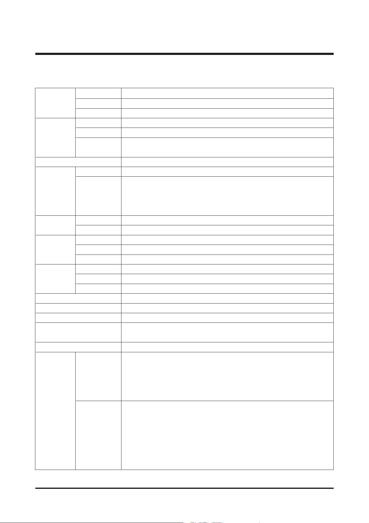
1. SPECIFICATION
Type 1/2.5" CCD
Effective Pixel Approx. 5.0 Mega-pixel
Total Pixel Approx. 5.1 Mega-pixel
Focal Length SHD Lens f = 6.6 ~ 19.8mm (35mm film equivalent : 39 ~ 117mm)
F No. F 3.5 ~ F 4.5
Still Image mode : 1.0X ~ 5.0X
Play mode : 1.0X ~ 10.1X (depends on image size)
LCD Monitor 2.5" color TFT LCD (230,000 pixels)
Type TTL auto focus
Normal : 50cm ~ infinity
Macro : 5cm ~ 50cm (Wide), 25cm ~ 50cm (Tele)
Super Macro : 1cm ~ 5cm (Wide)
Auto : 5cm ~ Infinity (Wide), 50cm ~ Infinity (Tele)
Type Mechanical and Electronic shutter
Speed 1 ~ 1/2,000 sec. (Night : 16 ~ 1/2,000 sec.)
Control Program AE Metering : Multi, Spot
Exposure Compensation ±2EV (0.5EV steps)
ISO Equivalent Auto, 100, 200, 400
Modes Auto, Auto & Red-eye reduction, Fill-in flash, Slow sync, Flash off
Flash Range Wide : 0.2m ~ 2.4m, Tele : 0.3m ~ 1.9m (ISO AUTO)
Recharging Time
Approx. 4 sec.
Sharpness Soft, Normal, Vivid
Effect Normal, B&W, Sepia, Negative, Red, Green, Blue, RGB
White Balance Auto, Daylight, Cloudy, Fluorescent_H, Fluorescent_L, Tungsten, Custom
Voice Recording (max. 1 hour)
Voice Memo in Still Image (max. 10 sec.)
Date Imprinting Off, Date, Date&Time (user selectable)
Modes : Auto, Manual, Scene, SF
※ Scene : Night, Portrait, Children, Landscape, Text, Close-up,
Sunset, Dawn, Backlight, Fireworks, Beach & Snow
Continuous : Single, Continuous
Self-timer : 2 sec., 10 sec., Double(10 sec., 2 sec.)
With Audio or without Audio
(user selectable, recording time :memory capacity dependent)
Size : 640x480, 320x240, 160x128 (3X Optical Zoom, Mute during Zoom Operation)
Frame rate : 30 fps, 15 fps
Movie Stabilizer (User Selectable)
Movie Editing (Embeded) : Pause during recording, Still Image Capture,
Time Trimming
Range
Digital Zoom
Image
Sensor
Lens
Focusing
Shutter
Shooting
Voice Recording
Movie Clip
Still Image
5
Ⅰ.SPECIFICATION
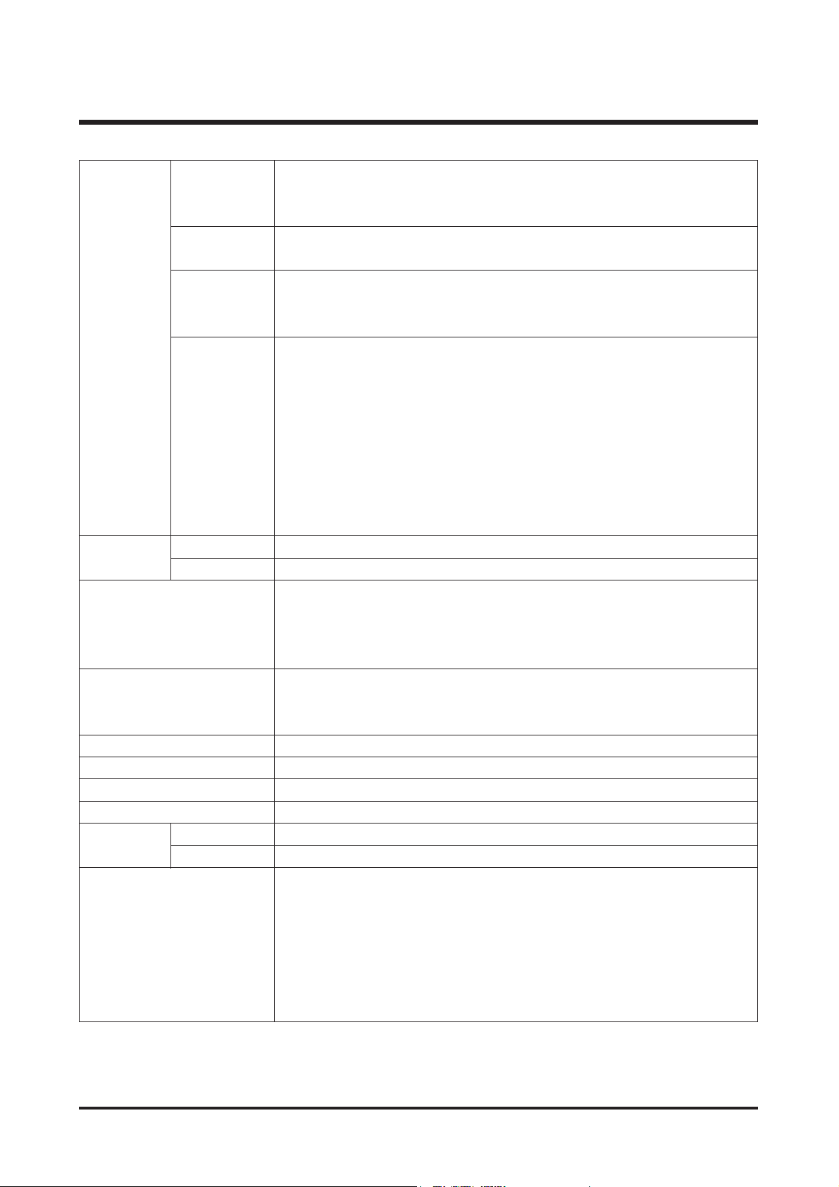
Internal memory : Approx. 48MB flash memory
External memory : SD card /MMC (Up to 1GB Guaranteed)
* Internal memory is subject to change without prior notice.
Still Image : JPEG (DCF), EXIF 2.2, DPOF 1.1, PictBridge 1.0
Movie Clip : AVI (MPEG-4) Audio : WAV
5M : 2592x1944 4M : 2272x1704
3M : 2048x1536 2M : 1600x1200
1M : 1024x768 VGA : 640x480
5M : Super Fine 11, Fine 21, Normal 32
4M : Super Fine 14, Fine 27, Normal 40
3M : Super Fine 17, Fine 33, Normal 49
2M : Super Fine 28, Fine 52, Normal 75
1M : Super Fine 66, Fine 111, Normal 151
VGA : Super Fine 149, Fine 217, Normal 275
※ These figures are measured under Samsung’s standard conditions and may
vary depending on shooting conditions, camera settings and memory card
type.
Type Single image, Thumbnails, Slide show, Movie Clip, Album
Editing Trimming, Resizing, Rotate, Effect
Digital output connector : USB 2.0
Audio : Mono
Video output : NTSC, PAL (user selectable)
DC power input connector : 4.2V
Rechargeable battery : 3.7V Li-ion battery (SLB-0737)
AC Charger : DC 4.2V, 450mA/ 760mA (SAC-41)
※ Included battery may vary depending on sales region.
Dimensions (WxHxD) 92.3 x 60.2 x 17.7 mm (excluding the projecting parts of the camera)
Weight Approx. 120g (without battery and card)
Operating Temperature 0 ~ 40°C
Operating Humidity 5 ~ 85%
Camera Driver Storage Driver (Windows98/98SE/2000/ME/XP, Mac OS 9.2 ~ 10.3)
Application Digimax Master, Digimax Reader
SF (Safety Flash)
MP3 Player function
3X Optical Zoom for Still & Movie.
New Charging System (Cradle (Optional))
MPEG-4 VGA 30fps Movie Clip (supporting Edit on DSC)
Powerful Effect (Colour, Highlight, Composite, Frame)
Quick Mode Change (M button, SF Button)
Capacity
(32MB)
Image Size
Storage
Image Play
Power Source
Interface
Special Features
Software
Media
File Format
6
Ⅰ.SPECIFICATION
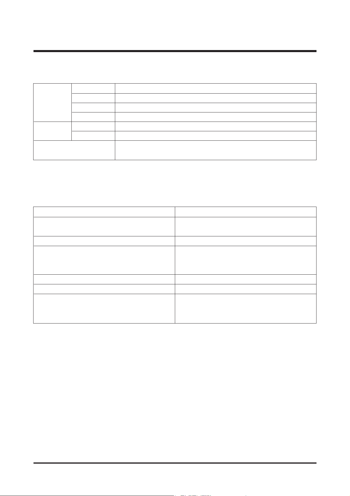
Frequency 20Hz~20KHz
Earphone Port 3.5mm Port (Stereo Type)
Output Maximum Volume Left 15mW + Right 15mW(16Ω)
Noise Ratio 85 dB with 20 KHz LPF
File Format MP3 (MPEG-1/2/2.5 Layer 3)
Bit Rate 48 ~ 320kbps (Including VBR)
One, All, Repeat One, Repeat All, Random,
Slide Show On/Off (User Selectable)
※ MP3 player
Audio
File
Play Mode
For Windows For Macintosh
PC with processor better than Pentium II 450Mz Power Mac G3 or later
(Pentium 700MHz recommended)
Windows 98/98SE/2000/ME/XP Mac OS 9.2 ~ 10.3
Minimum 64MB RAM (XP : 128MB) Minimum 64MB RAM
200MB of available hard disk space 110MB of available hard-disk space
(1GB recommended)
USB port USB port
CD-ROM drive CD-ROM drive
1024x768 pixels, 16-bit colour display QuickT ime player or a media player that
compatible monitor supports A VI file format
(24-bit colour display recommended) DivX (for movie clip)
2. SYSTEM REQUIREMENTS
7
Ⅰ.SPECIFICATION
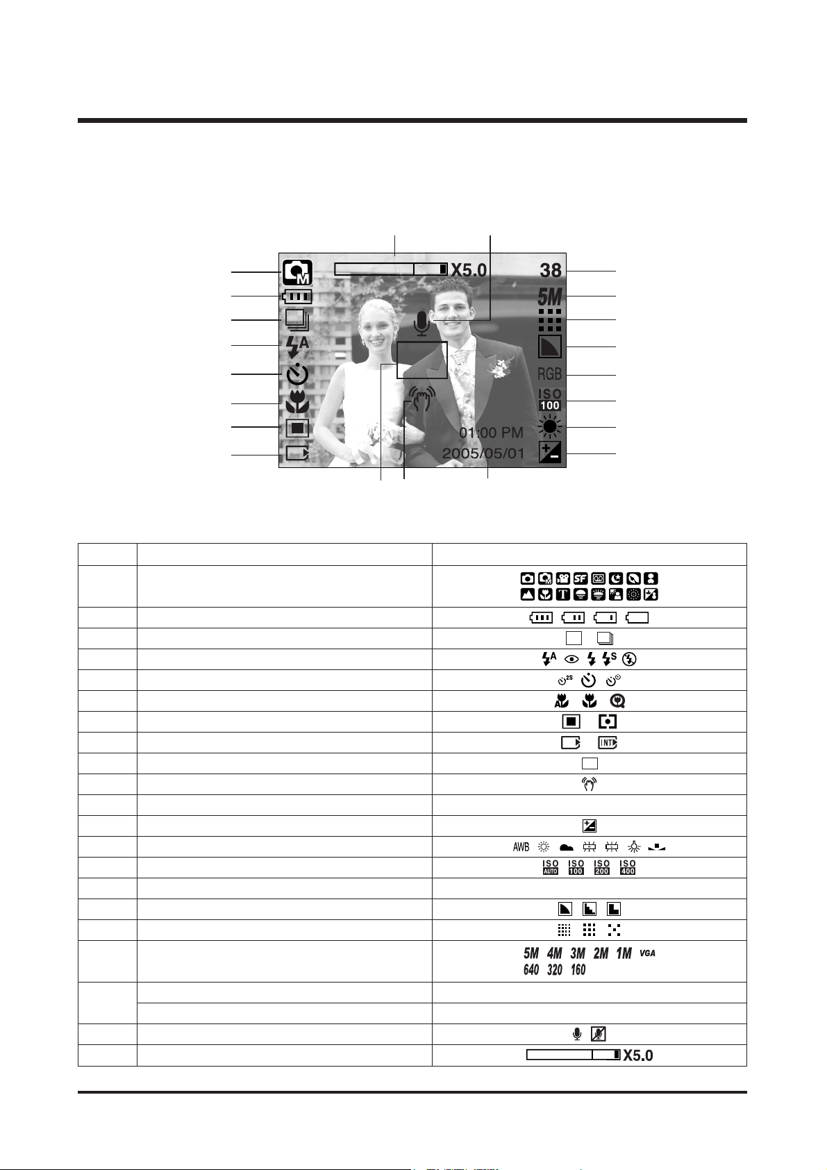
■ Recording Mode
3. TFT LCD PANEL MARK
No. Description Icon
2 Battery
3 Continuous shot
4 Flash
5 Self-timer
6 Macro
7 Metering
8 Card inserted indicator
9 Auto focus frame
10 Camera shake warning
11 Date/Time 2005/05/01 01:00 PM
12 Exposure compensation
13 White Balance
14 ISO
15 RGB RGB
16 Sharpness
17 Image qualit
Number of available shots remaining 38
Remaining time(Movie clip/Voice recording) 00:01:30/ 01:00:00
20 Voice memo/Mic.off
21 Optical/Digital Zomm bar/Digital Zoom rate
Recording mode
1
19
18
①
②
③
④
⑤
⑥
⑦
⑧
⑬
⑫
⑭
⑮
⑰
⑯
⑱
⑲
⑩⑨
⑪
⑳
Image Size
8
Ⅰ.SPECIFICATION
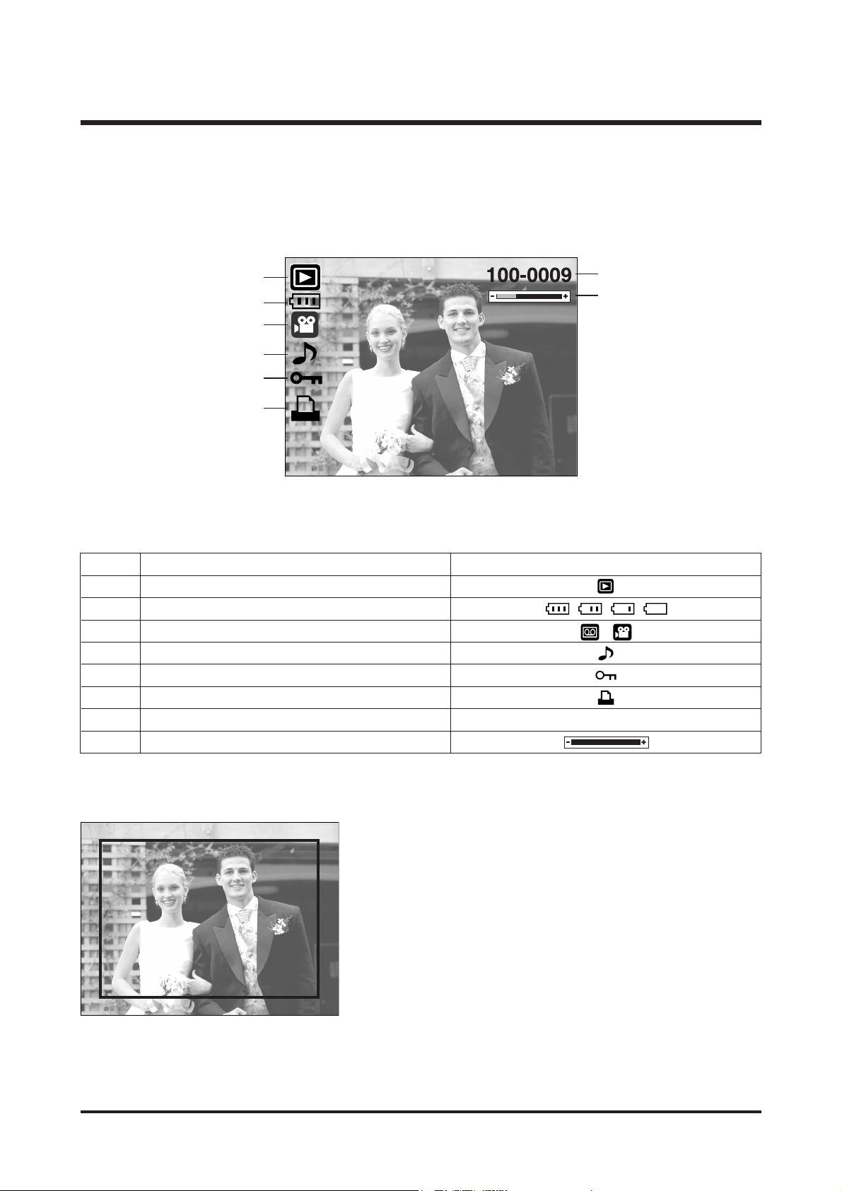
■ Play Mode
No. Description Icon
1 Playmode
2 Battery
3 File Type
4 Voice memo
5 Protectindicator
6 DPOF indicator
7 Folder name and Stored image number 100-0009
8Volume display
⑦
⑧
②
①
③
④
⑤
⑥
SIZE : 2592X1944 Size
AV : F3.5 Aperture value
TV : 1/60 Shutter speed
ISO : 100 ISO sensitivity
FLASH : OFF Whether or not the
flash is used
DATE : 2005/05/01 Recording date
Size : 2592X1944
Av : F3.5
Tv : 1/60
ISO : 100
Flash : Off
Date : 2005/05/01
9
Ⅰ.SPECIFICATION
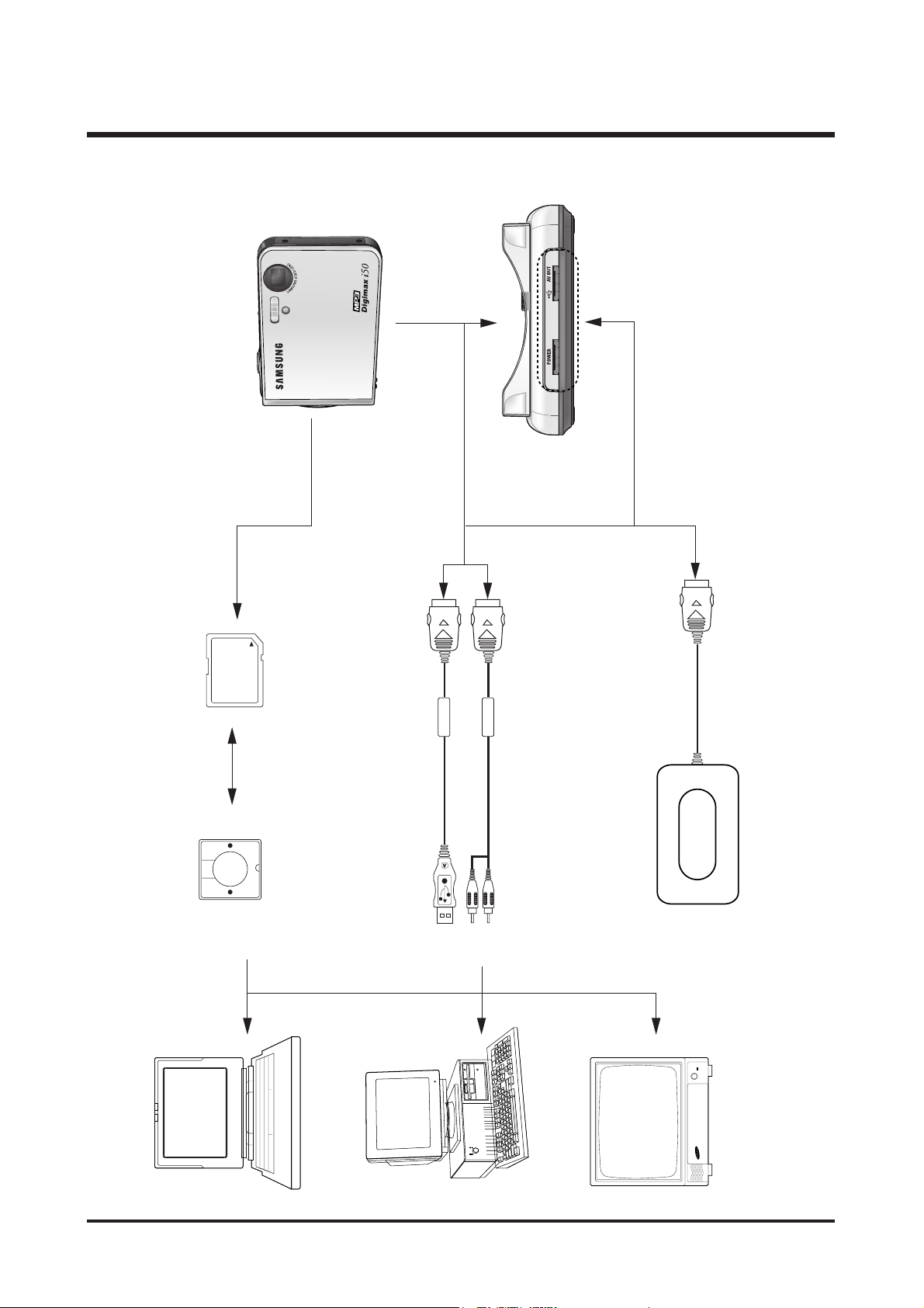
4. CONNECTION DIAGRAM
TV Monitor
IBM / MAC
Lap top
Card Reader SD Card
AC Adaptor
USB Cable
AV Cable
10
Ⅰ.SPECIFICATION
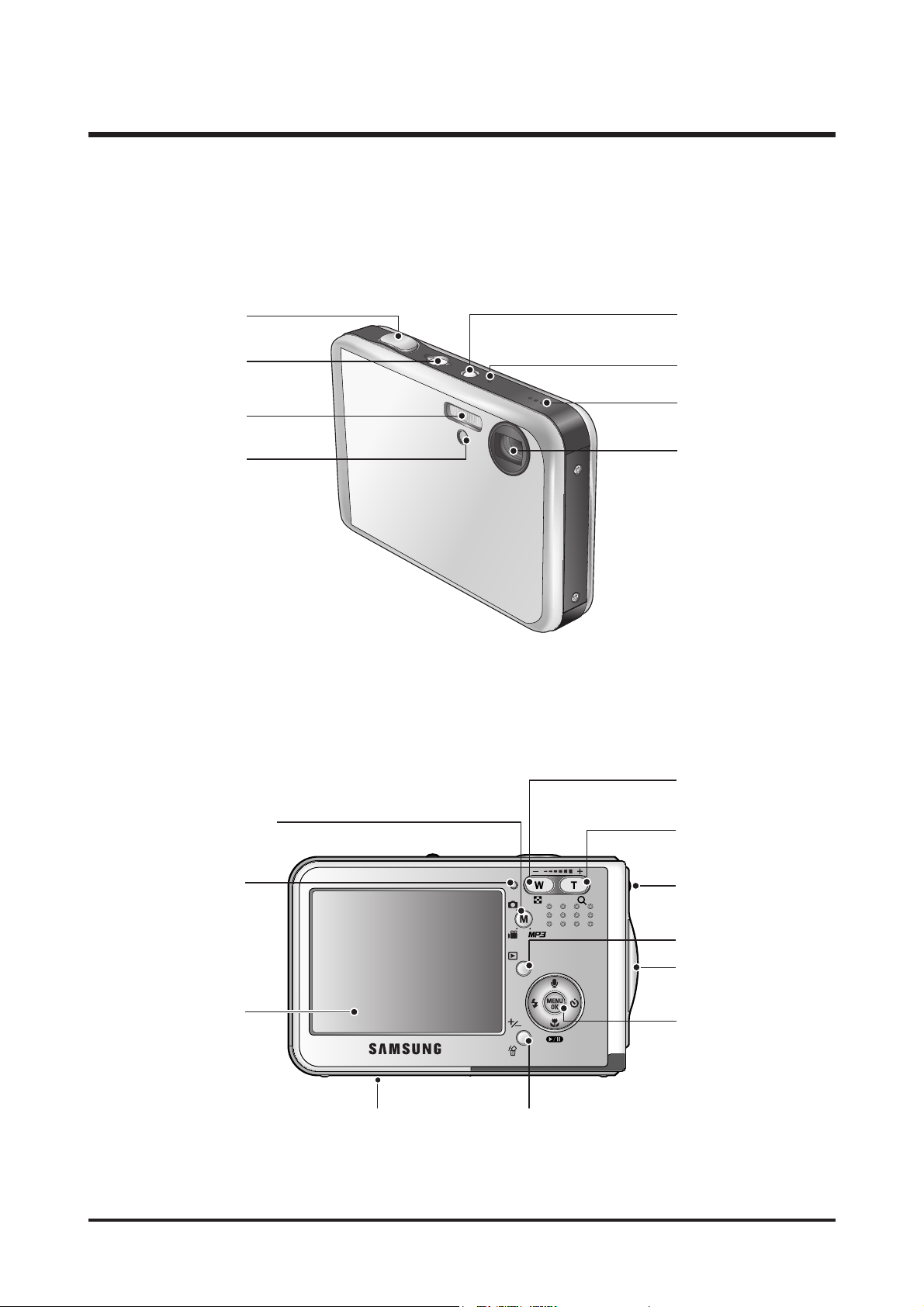
5. IDENTIFICATION OF FEATURES
Flash
Self-timer lamp
/Auto Focus lamp
Power button
Shutter botton
SF mode button/
Hold button
Speaker
Microphone
Optical 3X zoom lens/
Lens cover
LCD monitor
+/-, DELETE button
5 function button
DC/USB/AV connection terminal
Cradle connector
Earphones Jack
Strap eyelet
Play mode button
Zoom T button
(Digital zoom, Vol. Up)
Zoom W button
(Thumbnail, Vol. Down)
M(Mode/Album) button
Camera status lamp
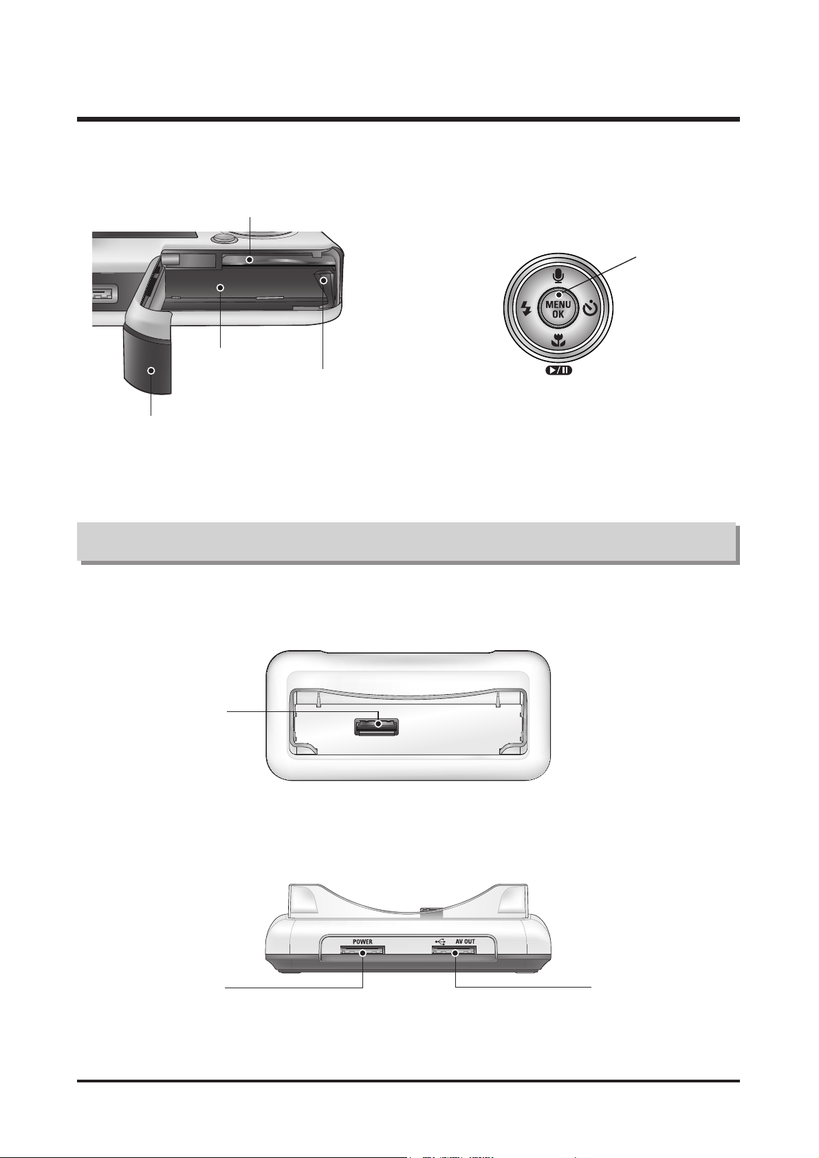
11
Ⅰ.SPECIFICATION
● Back
● To p
Battery holder
Memory card slot
Battery chamber
Battery chamber cover
FLASH/
LEFT button
MENU/
OK button
Macro/ DOWN button
Play & Pause button
SELF-TIMER/
RIGHT button
Voice memo/ UP button
Cradle
Camera connection
terminal
USB port
AV connection terminal
DC connection terminal
12
Ⅱ.INSTALLATION
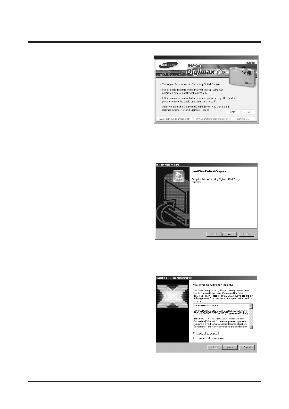
1. Click the [Install] menu in the Auto run frame.
The camera driver is installed automatically.
2. Installation is complete.
Click the [Finish] button.
3. The Software License Agreement window for
DirectX will be displayed. If you agree to this, select
[I accept the agreement] and click [Next >] button.
the window will then move to the next step.
If you disagree, select [I do not accept the
agreement] and click [Cancel] button.
The installation program will be cancelled.
13
Ⅱ.INSTALLATION
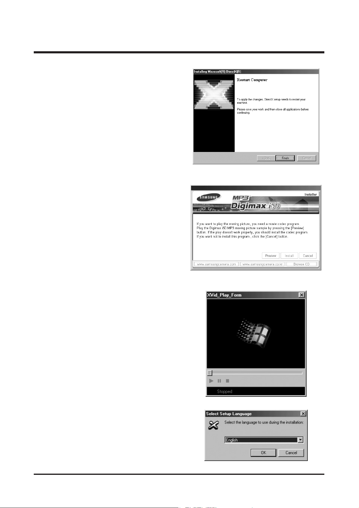
5. DirectX Installation is completed.
Click the [Finish] button and then the Xvid codec
installation will be started.
* The system will not reboot even if you click the
[Finish] button.
* The screen shot of step 5 can be different from
the illustration depending on the system
requirements.
6. A windows to check whether the PC has XviD
codec or not will display.
[Preview] : You can check the movie clip display
condition.
[Install] : The XviD codec is installed.
[Cancel] : The XviD codec is not installed and a
window for installing the application
softwares will display.
※ If you didn’t click the [Preview] button, the [Install]
button can’t be selected.
7. If an error listed below takes place during the
preview, click the [Install] button to install the XviD
codec.
- Only a voice plays back.
- An error message displays and the movie clip
does not play back.
* A window shown alongside may display
according to the system requirements.
14
Ⅱ.INSTALLATION
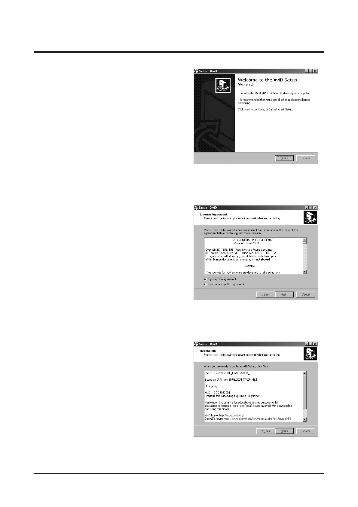
8. The XviD codec installation window will be
displayed as shown alongside. Click the [Next >]
button.
10. The XviD information window will display.
Click the [Next >] button.
9. The Software License Agreement window will be
displayed. If you agree to this, select [I accept the
agreement] and click [Next >] button.
The window will then move to the next step.
If you disagree, select [I do not accept the
agreement] and click [Cancel] button. The
installation program will be cancelled.
※ The XviD codec is distributed according to the
GNU General Public License and everyone can
copy, distribute and change this codec. For more
information, see the License documents.
15
Ⅱ.INSTALLATION
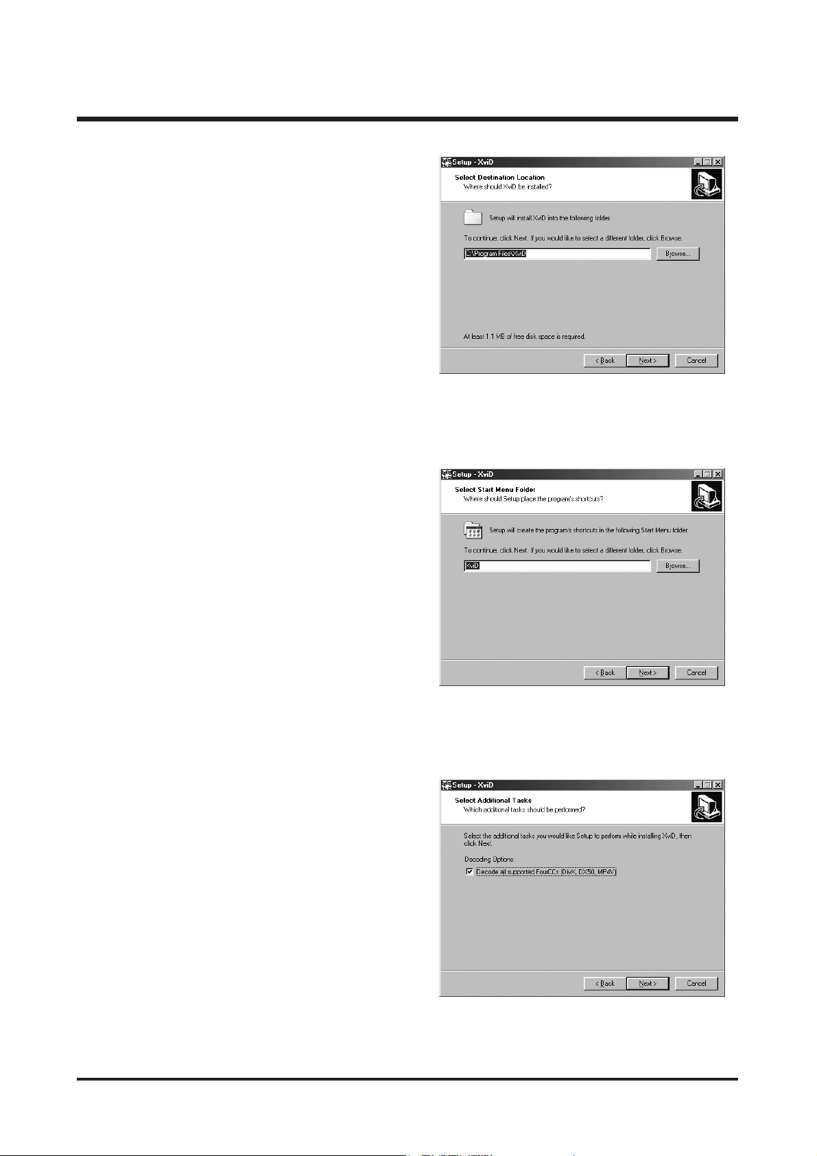
11. The destination selection window will open.
Click [Next >] button.
To copy to the files to another folder, click
[Browse...] and choose a folder you want.
12. A window will open, asking you to choose a folder
to which program icons will be added.
Click [Next >] button. If you want to add the
program icons to a different folder, choose another
folder, and then click [Next >] button.
13. The [Select Additional Tasks] window will display.
Select the additional tasks and click the
[Next >] button.
16
Ⅱ.INSTALLATION
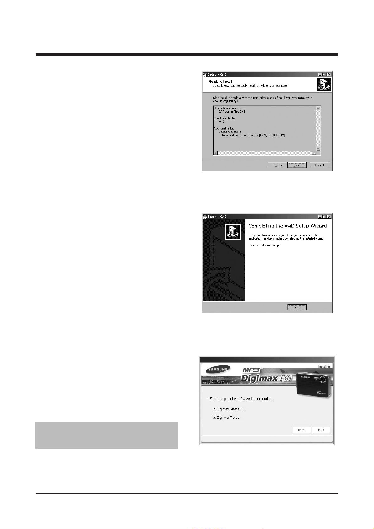
16. A window where you can choose the program you
want to install will appear. Click [Install].
15. Installation is complete.
Click the [Finish] button.
14. The XviD codec is ready to install.
Click the [Install] button.
● If you select [Exit] at step 16, the application
program installation will be cancelled.
17
Ⅱ.INSTALLATION
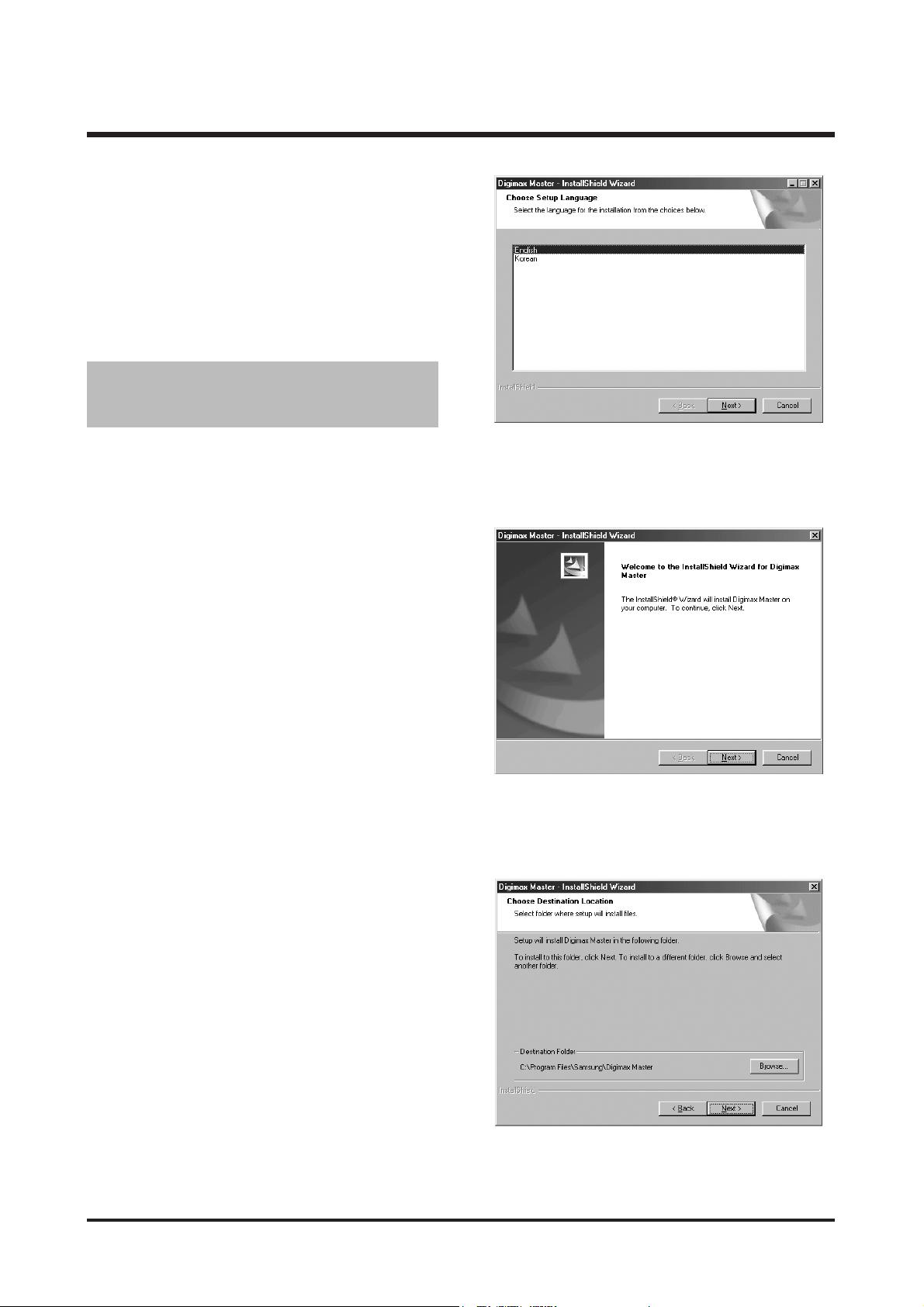
17. The Digimax Master installation window will be
displayed as shown alongside.
Click the [Next >] button.
19. A destination selection window will open. Click
[Next >].
To copy the files to another folder, click [Browse..]
and choose a folder you want.
18. A window will open. Click the [Next >] button.
● If you select [Cancel] at step 17, a window for
installing Digimax Reader will be displayed.
18
Ⅱ.INSTALLATION
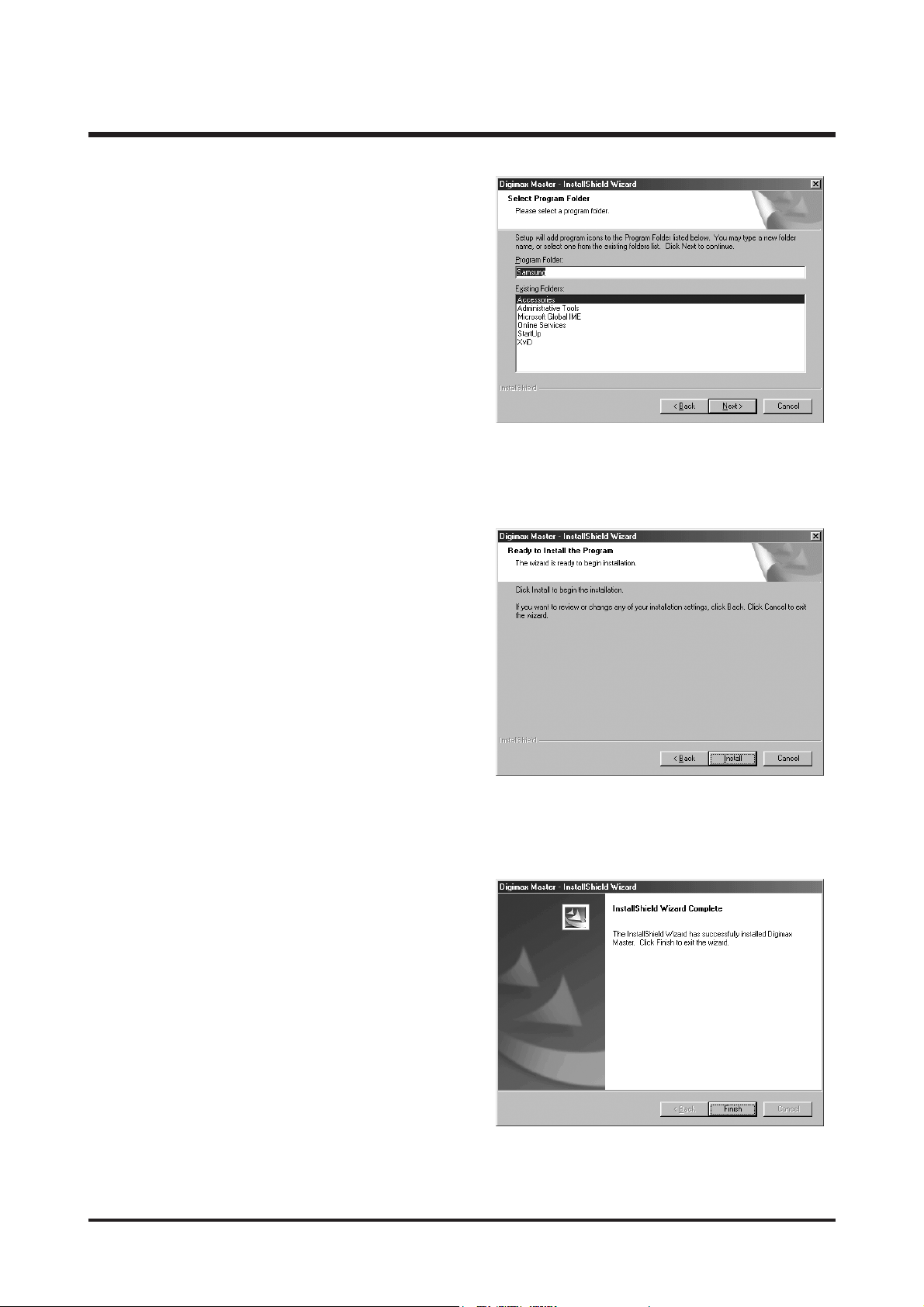
21. Click [Install(I)] button and Digimax Master starts
installing.
20. A window will open, asking you to choose a folder
to which program icons will be added.
Click [Next >] button.
If you want to choose another folder, click
[Browse..] and choose a folder you want.
22. Digimax Master installation is successfully
completed.
Click the [Finish] button to install Digimax Reader.
* The screen shot of step 22 can be different from
the illustration depending on the system
requirements.
19
Ⅱ.INSTALLATION
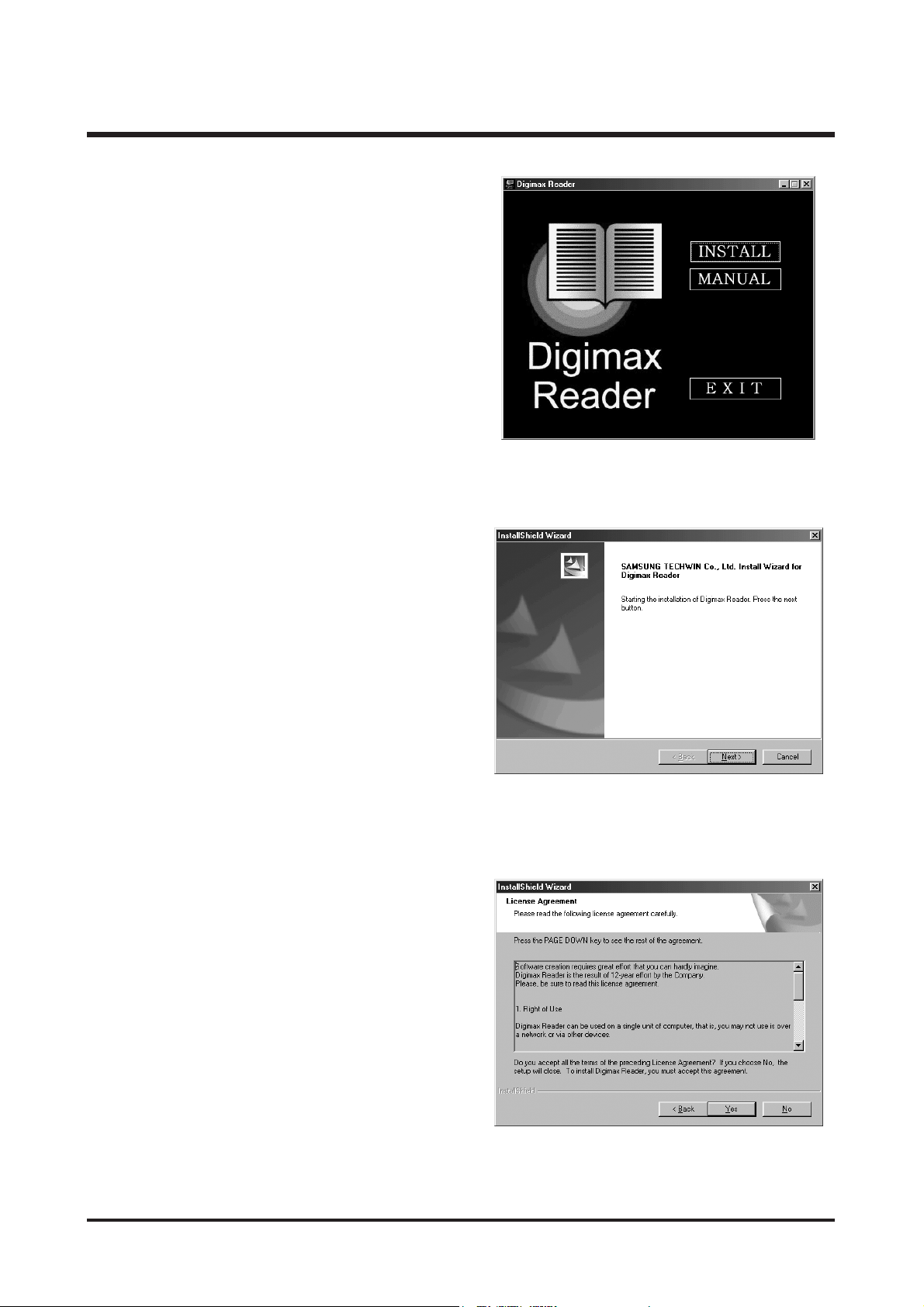
23. A window will be displayed as shown alongside.
Click the [INSTALL] button.
- If you click the [Manual] button, instructions for
using Digimax reader will be displayed.
- Click the [EXIT] button and the Digimax reader
installation will be cancelled and a window for
restarting the computer will appear.
24. A window will open. Click the [Next >] button.
25. The Software License Agreement window will be
displayed. If you agree to this, click [Yes],
the window will then move to the next step.
If you disagree, click [No] and the installation
program will be cancelled.

20
Ⅱ.INSTALLATION
26. A destination selection window will open. Click
the [Next >] button.
To copy the files to another folder, click [Browse...]
and choose a folder you want.
28. To apply changes, you must restart the computer.
Select [Yes, I want to restart my computer now],
and then click the [OK] button.
29. After restarting the computer, connect the PC to the camera with the USB cable.
27. Digimax Reader Installation is completed.
The system will not reboot even if the [Yes, I want
to restart the computer now] option is selected.
※ The screen shot of step 27 can be different from
the illustration depending on the system
requirements.
21
Ⅱ.INSTALLATION
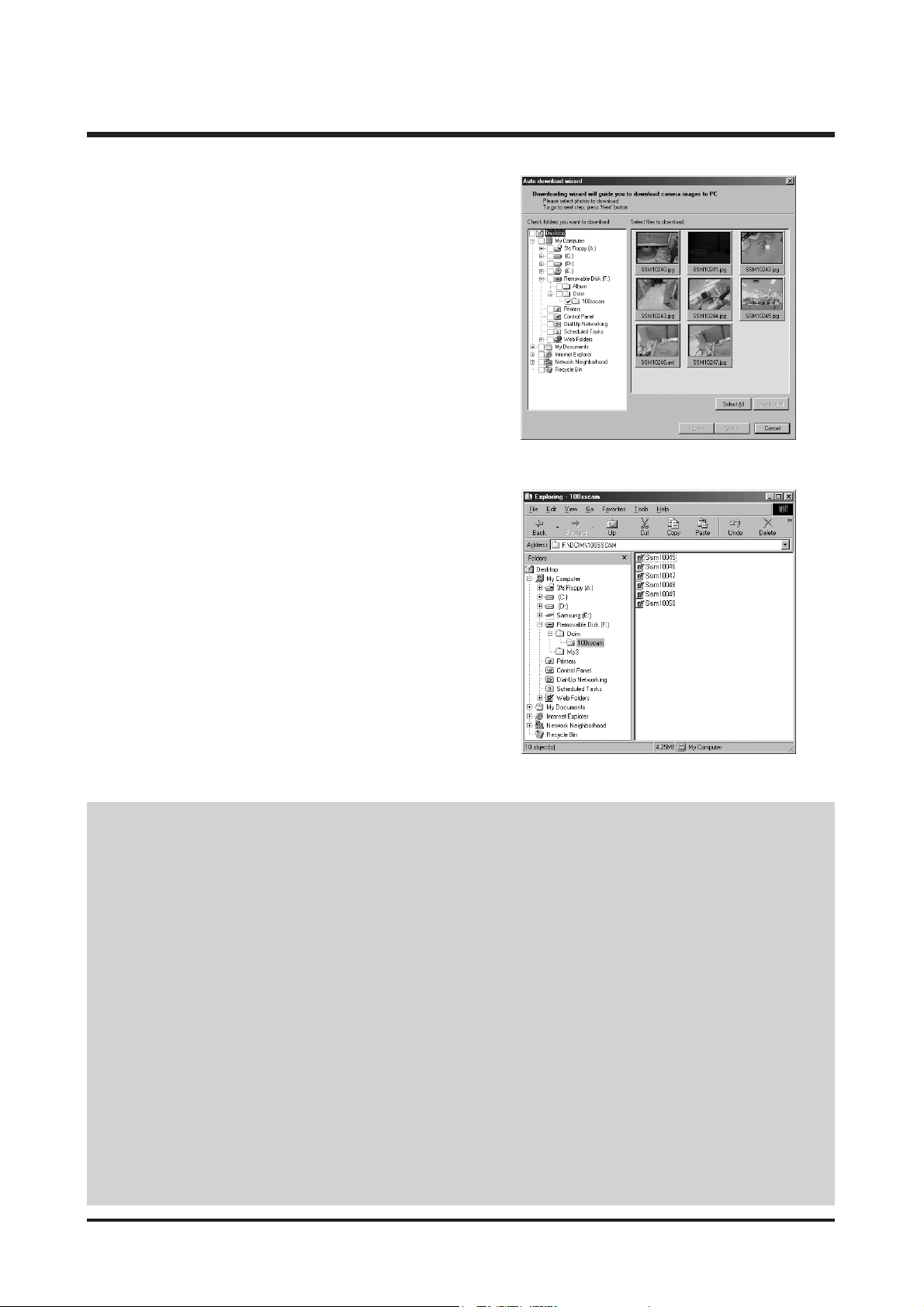
30. Turn the camera power on.
The [Found New Hardware Wizard] will open and
the computer will recognise the camera.
* If your OS is Windows XP, an image viewer
program will open.
If the download window of Digmax Master opens
after starting Digimax Master, the camera driver
was setup successfully.
31. If you can see [Removable Disk] under [My
computer], the camera driver installation was
successful.
Now you can transfer image files from the camera
to PC via the USB cable.
● If you have installed the camera driver, The [Found New Hardware Wizard] may not open.
● On a Windows 98 or 98 SE system, the Found New Hardware Wizard dialog box opens and a window
asking you to select a driver file may appear. In this case, specify "USB Driver" in the CD supplied. (for
Windows 98 and 98 SE).
● Before connecting the camera to the PC, You should first install the camera driver.
● After installing the camera driver, you have to restart your PC.
● If you connect the camera to the PC before installing the camera driver, the [Found New Hardware Wizard]
will open.
In this case, cancel the [Found New Hardware Wizard] and disconnect the camera.
Install the camera driver and connect the camera to the PC again.
● Should the computer not find the camera driver after installation, please try one or more of the following
measures.
1. Delete the camera driver, and re-install the driver.
2. Refer to FAQ to check for a possible solution to the problem.
3. If your PC’s central processing unit is VIA chip (This is shown in the USB Host Controller), download the
patch file from the Samsung Camera web page. (http://www.samsungcamera.com)
22
Ⅲ.EXPLODEDVIEWANDPARTLIST
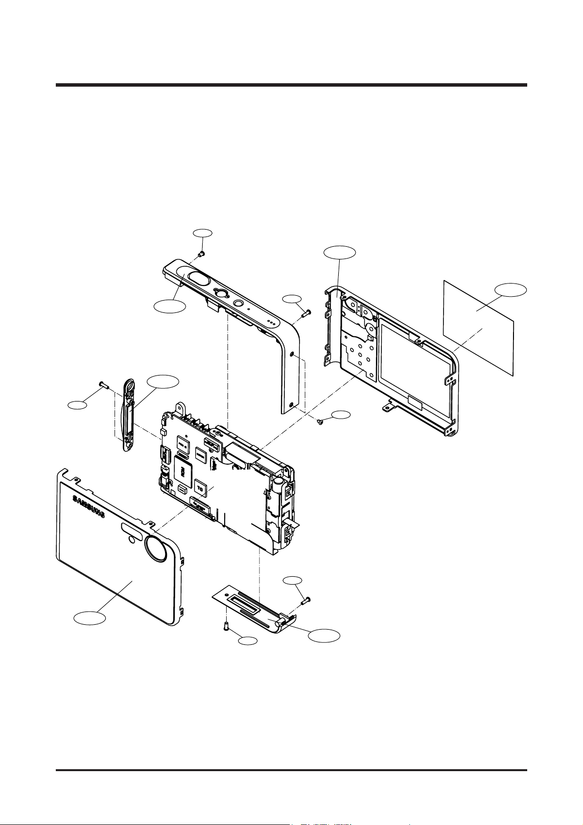
1-1
1-3
1-10
1-7
1-5
1-2
1-11
1-6
1-8
1-9
1-4
1-9
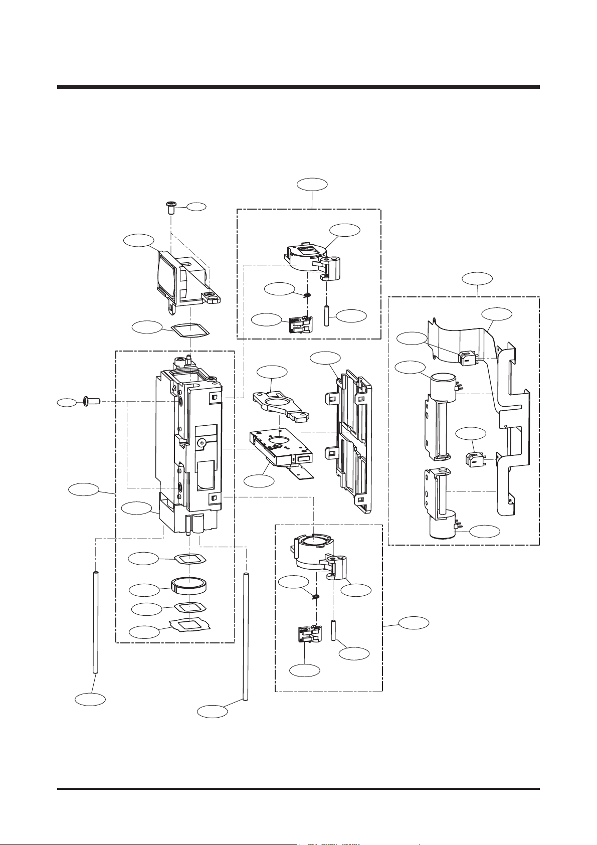
1. MAIN ASSEMBLY

23
Ⅲ.EXPLODEDVIEWANDPARTLIST
▶
PARTS LIST
1-1 Q9007246901A FRONT ASSY-KENOX #1 MP3 1 O SILVER
Q9007243301A FRONT ASSY-DIGIMAX i50 MP3 1 O SILVER
Q9007247101A FRONT ASSY-DIGIMAX i50 MP3 1 O BLACK
Q9007247001A FRONT ASSY-KENOX #1 MP3 1 O BLACK
Q9007247301A FRONT ASSY-DIGIMAX i50 MP3 1 O RED
Q9007247201A FRONT ASSY-KENOX #1 MP3 1 O RED
1-2 Q9007243501A BACK COVER ASSY 1 O SILVER
Q9007246601A BACK COVER ASSY 1 O BLACK
Q9007246701A BACK COVER ASSY 1 O RED
1-3 Q7217359805A BOTTOM COVER 1 O
1-4 Q9761173007 SCREW 1 X
1-5 Q9007244101A STRAP COVER ASSY 1 O
1-6 Q6001018201A SCREW 2 X
1-7 Q9007246501A MIDDLE COVER ASSY-KENOX 1 O
Q9007243601A
MIDDLE COVER ASSY-DIGIMAX+C151
1O
1-8 Q9761174001 SCREW 1 X
1-9 Q6003018501A SCREW 2 X
1-10 Q7409197501A LCD PROTECT SHEET 1 O
1-11 Q6000107701A SCREW 2 X
Fig.No Parts No. Parts Name Q’ty
Supply Available Parts
Remarks
24
Ⅲ.EXPLODEDVIEWANDPARTLIST
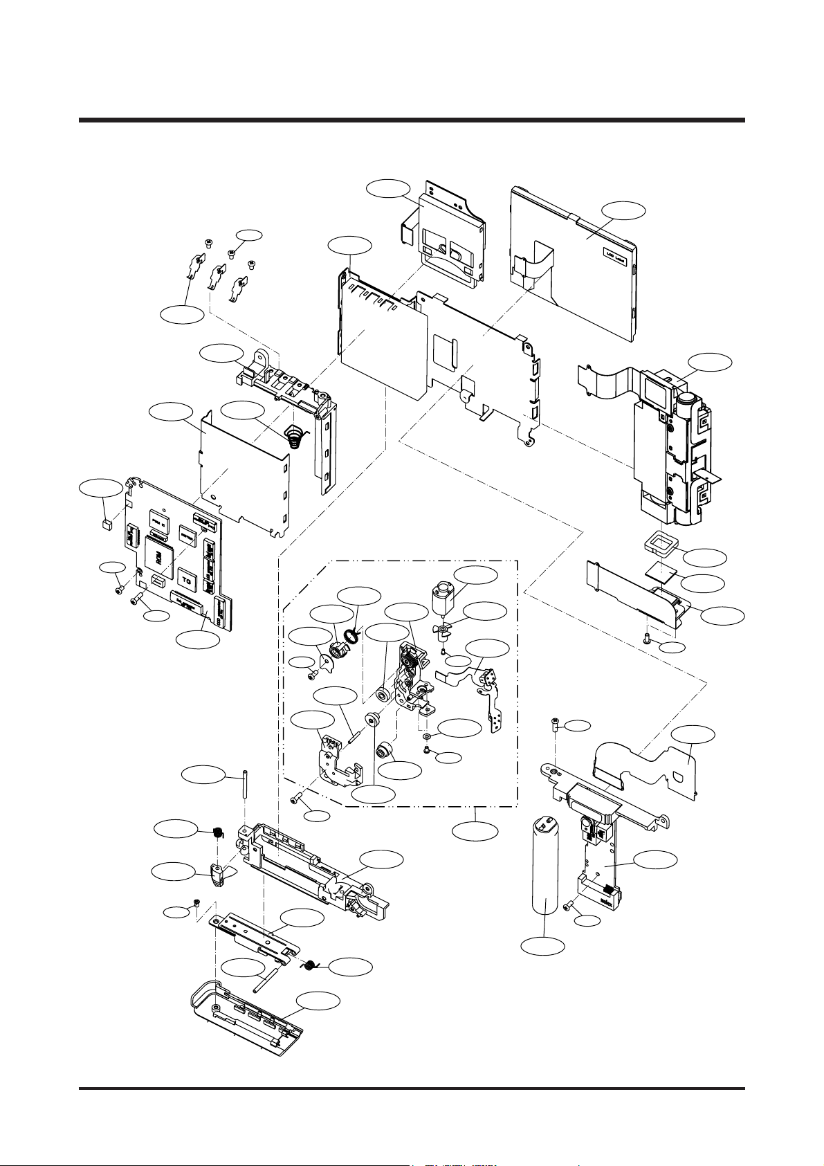
2-17
2-35
2-36
2-34
2-9
2-10
2-13
2-8
2-16
2-11
2-12
2-14
2-20
2-19
2-46
2-41
2-38
2-39
2-37
2-33
2-21
2-31
2-29
2-26
2-25
2-18
2-24
2-27
2-23
2-46
2-22
2-1
2-5
2-4
2-6
2-7
2-3
2-44
2-40
2-45
2-42
2-28
2-32
2-47
2-15
2-44
2-43
2-30
2-2
2. BODY ASSEMBLY

25
Ⅲ.EXPLODEDVIEWANDPARTLIST
▶▶
PARTS LIST
2-1 Q9008092901A MAIN PCB ASSY 1 O
2-2 Q7211081403A BATTERY UPPER HOLDER 1 O
2-3 Q6107064001A BATTERY SPRING 1 O
2-4 Q7011052901A BATTERY CONTACT 3 O
2-5 Q7011053206A BATTERY TOP COVER 1 O
2-6 Q7011053305A MAIN FRAME 1 O
2-7 Q9007232401A TFT LCD ASSY 1 O
2-8 Q7411119304A BATTERY HINGE 2 O
2-9 Q6107063703A BATTERY HINGE SPRING 1 O
2-10 Q7211082404A BATTERY BOTTOM HOLDER 1 O
2-11 Q7103003305A BATTERY LOCK 1 O
2-12 Q6107063803A BATTERY LOCK SPRING 1 O
2-13 Q7217359904A BATTERY COVER 1 O SILVER
Q7217367801A BATTERY COVER 1 O BLACK
Q7217367601A BATTERY COVER 1 O RED
2-14 Q7411119203A BATTERY LOCK PIN 1 O
2-15 Q6003045001A SCREW 1 X
2-16 Q9001105001A BATTERY PLATE ASSY 1 O
2-17 Q9001103501A MOTOR ASSY 1 O
2-18 Q7017048201A ROTATOR PLATE 1 O
2-19 Q7217352606A LC GEAR BASE 1 O
2-20 Q7217352704A LC GEAR COVER 1 O
2-21 Q7212177003B ZOOM MOTOR GEAR 1 O
2-22 Q7217351202A LC GEAR_A 1 O
2-23 Q7217351301A LC GEAR_B 2 O
2-24 Q7217351401A LC IDLE GEAR 1 O
2-25 Q7217351508A LC ROTATOR GEAR 1 O
2-26 Q6107063603A ROTATOR SPRING 1 O
2-27 Q7411118701A LC GEAR SHAFT 2 O
2-28 Q7411118803A LC MOTOR GEAR PIN 1 O
2-29 Q9001104101A LC MOTOR PCB ASSY 1 O
2-30 Q6001010601A SCREW 1 X
2-31 Q6031006601A MOTOR WASHER 1 X
2-32 Q6001017601A SCREW 2 X
2-33 Q9001104301A CARD ASSY 1 O
2-34 Q9008086801A MAIN CONDENSER ASSY 1 O
2-35 Q9008086901A SUB PCB ASSY 1 O
2-36 Q4101034202A SUB CONNECTOR FPCB 1 O
2-37 Q9002138201A SZC5325 BARREL ASSY 1 O
2-38 Q2904003001A IR CUT FILTER 1 O
2-39 Q7309046101B OLPF CUSHION 1 O
2-40 Q0961900301A SCREW 2 X
2-41 Q9008093201A CCD FPCB ASSY 1 O
2-42 Q9761174007 SCREW 1 X
2-43 Q0961900301A SCREW 1 X
2-44 Q0961900101A SCREW 3 X
2-45 Q6001007901A SCREW 1 X
2-46 Q7409155401A SHIELD FORM_A 1 X
2-47 Q6003018501A MACHINE SCREW 1 X
Fig.No Parts No. Parts Name Q’ty
Supply Available Parts
Remarks
26
Ⅲ.EXPLODEDVIEWANDPARTLIST
3. BARREL ASSEMBLY
3-28
3-27
3-10
3-11
3-19
3-13
3-20
3-26
3-12
3-14
3-21
3-25
3-8
24
3-
3-22
3-21
3-7
3-1
3-2
3-23
3-3
3-13
3-4
3-16
3-9
3-5
3-15
3-6
3-14
3-17
3-18

27
Ⅲ.EXPLODEDVIEWANDPARTLIST
▶▶
PARTS LIST
3-1 Q9002138001A 5TH BARREL ASSY 1 O
3-2 Q7212185008A LENS BASE 1 O
3-3 Q7012083402A G11 MASK_A 1 O
3-4 Q6713005001A G11 LENS 1 O
3-5 Q7012082501A G11 MASK 1 O
3-6 Q7409179001A REAR SHEET 1 O
3-7 Q9005017801A SHUTTER ASSY 1 O
3-8 Q9002135301A 3RD LENS BARREL ASSY 1 O
3-9 Q7411115602A GUIDE BAR_B 1 O
3-10 Q9002137801A 2ND CLIP ASSY 1 O
3-11 Q9002135201A 2ND MOVE BARREL ASSY 1 O
3-12 Q7212185604A 2ND CLIP 1 O
3-13 Q6107060603A CLIP SPRING 1 O
3-14 Q7411115701A CLIP GUIDE BAR 1 O
3-15 Q9002137901A 4TH CLIP ASSY 1 O
3-16 Q9002135401A 4TH MOVE BARREL ASSY 1 O
3-17 Q7212185704A 4TH CLIP 1 O
3-18 Q7411115502A GUIDE BAR_A 1 O
3-19 Q9002138101A MAIN FPCB ASSY 1 O
3-20 Q4101030402A MAIN FPCB 1 O
3-21 Q0608001001A PHOTO INTERRUPTER 2 O
3-22 Q3107002201A 2nd MOTOR 1 O
3-23 Q3107002301A 4th MOTOR 1 O
3-24 Q6003000201A SCREW B 2 X
3-25 Q7212185502A BARREL COVER 1 O
3-26 Q7012082701A G3 MASK 1 O
3-27 Q9002135101A 1ST LENS BARREL ASSY 1 O
3-28 Q0961900101A SCREW 2 X
Fig.No Parts No. Parts Name Q’ty
Supply Available Parts
Remarks
28
Ⅲ.EXPLODEDVIEWANDPARTLIST
4-4
4-2
4-3
4-1
4-6
4-8
4-9
4-5
4-7
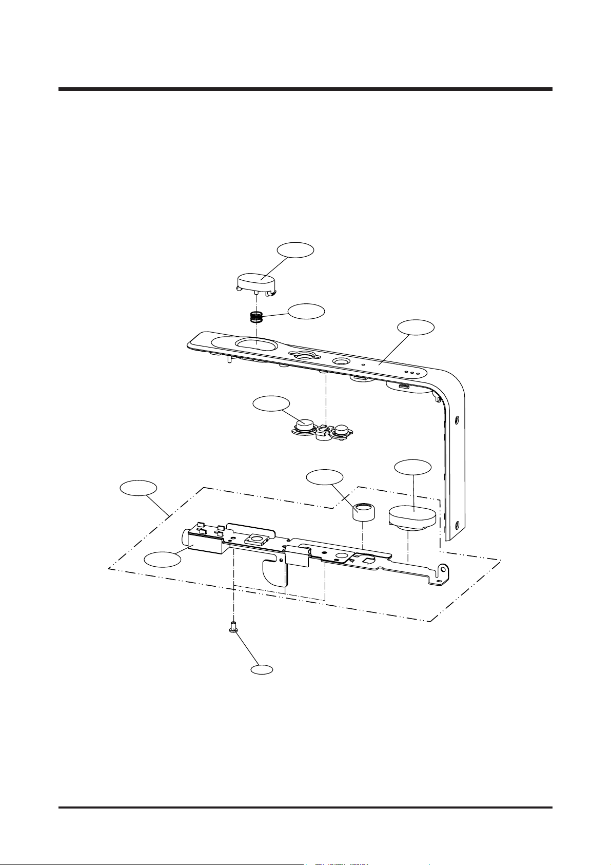
4. MIDDLE COVER ASSEMBLY

29
Ⅲ.EXPLODEDVIEWANDPARTLIST
▶▶
PARTS LIST
4-1 Q7217371601A MIDDLE COVER 1 O KENOX
Q7217359707A MIDDLE COVER 1 O DIGIMAX
4-2 Q7217360102A RELEASE BUTTON 1 O
4-3 Q7217352302A POWER BUTTON 1 O
4-4 Q6107063901A RELEASE SPRING 1 O
4-5 Q3001000601A SPEAKER 1 O
4-6 Q3003000401A MIC 1 O
4-7 Q0961900101A SCREW 3 X
4-8 Q9007243701A TOP PLATE ASSY 1 O
4-9 Q3722003801A EARPHONE JACK 1 O
Fig.No Parts No. Parts Name Q’ty
Supply Available Parts
Remarks
30
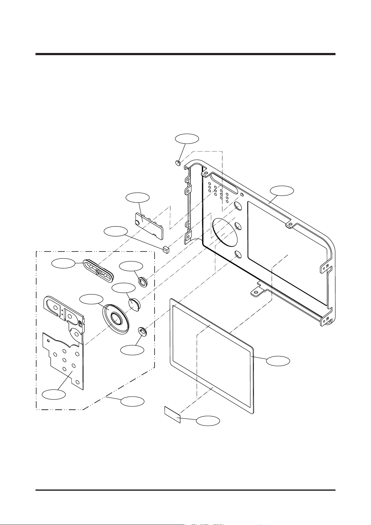
Ⅲ.EXPLODEDVIEWANDPARTLIST
5-12
5-13
5-8
5-6
5-7
5-9
5-10
5-5
5-11
5-1
5-2
5-3
5-4
5. BACK COVER ASSEMBLY
 Loading...