

DIGITAL CABLE RECEIVER
SERVICE
ΠDigital Cable HD Receiver for DVB-C
´ MPEG2 and H.264 Decoding
ˇ HDMI(HDCP)
¨ Teletext and subtitle
ˆ EPG (Now and Next)
Manual
DIGITAL CABLE RECEIVER Merit & Character regarding Product
SERVICE MANUAL
DCB-H360R/DCB-H360RS/DCB-H360RA
© Samsung Electronics Co., Ltd. JAN. 2007
Printed in Korea
MF82-00244A
This Service Manual is a property of Samsung Electronics Co.,Ltd.
Any unauthorized use of Manual can be punished under applicable
international and/or domestic law.
• This Service Manual is for DCB-H360RA(S).
In appearance, there is no difference between DCB-H360R(S) and DCB-H360RA(S) because two models have the same Ass’y
Front Cabinet.
We can identify DCB-H360RA from DCB-H360R by the model name of Label-Rating on Chassis-Rear.
and the existence of HDMI Transmitter(U1101) on Assy Main.
• How to identify them by Label-Rating ; See next page.
When servicing, be sure to confirm the model name on Label-Rating of Chassis-Rear.
BASIC :
DCB-H360R
Application Models :
XEE, XEN
ELECTRONICS
DCB-H360R / DCB-H360RS /
DCB-H360RSA
Application Areas :

CONTENTS
1. Precautions 1-1 ~ 1-4
1-1 Safety Precaution (1-1)
1-2 Servicing Precautions (1-3)
1-3 ESD Precautions (1-4)
2. Product Specification 2-1 ~ 2-4
2-1 Product Specification (2-1)
2-2 Chassis Product Specification) (2-2)
2-3 Option Product Specification (2-3)
3. Software Update 3-1 ~ 3-2
3-1 To Upgrade the Software (3-1)
4. Disassembly and Reassembly 4-1 ~ 4-4
4-1 Cabinet and PCB (4-1)
5. Trouble Shooting 5-1 ~ 5-12
6. Exploded View and Parts List 6-1 ~ 6-2
7. Electrical Parts List 7-1 ~ 7-14
8. Block Diagrams 8-1 ~ 8-6
8-1 All Block Diagram (8-2)
8-2 U301, U302(K4D261638I) Block Diagram (8-3)
8-3 U2001(LV5045) Block Diagram (8-4)
8-4 U210(S5H2600X) Block Diagram (8-5)
9. Wiring Diagram 9-1 ~ 9-2

10. PCB Diagrams 10-1 ~ 10-8
10-1 Main PCB (10-2)
10-2 S.M.P.S PCB (10-5)
10-3 Front PCB (10-7)
11. Schematic Diagrams 11-1 ~ 11-22
11-1 Tuner (Main PCB) (11-2)
11-2 S5H2600_H.264_Main (Main PCB) (11-3)
11-3 S5H2600_H.264_DDR I/F (Main PCB) (11-4)
11-4 S5H2600_H.264_Power & GND (Main PCB) (11-5)
11-5 TS_IO/CAP_IO (Main PCB) (11-6)
11-6 DDR_DDR-CTL (Main PCB) (11-7)
11-7 Flash_LAN I/F (Main PCB) (11-8)
11-8 PCI_PCI I/F (Main PCB) (11-9)
11-9 System_GPIO_IIC_SC I/F (Main PCB) (11-10)
11-10 Audio Out (Main PCB) (11-11)
11-11 HDMI (Main PCB) (11-12)
11-12 VCXO_System Clock (Main PCB) (11-13)
11-13 Dual Scart I/F (Main PCB) (11-14)
11-14 Dual Scart Connector (Main PCB) (11-15)
11-15 Smart Card (Main PCB) (11-16)
11-16 GPIO-Expander_CS (Main PCB) (11-17)
11-17 Reset_JTAG_Front IF_RS232C_EEPROM (Main PCB) (11-18)
11-18 S5H2100_Power_GND (Main PCB) (11-19)
11-19 Main_DC Core Power (Main PCB) (11-20)
11-20 S.M.P.S (S.M.P.S PCB) (11-21)
11-21 Front (Front PCB) (11-22)
12. Operating Instructions and Installation 12-1 ~ 12-32
CONTENTS

13. Circuit Operating Descriptions 13-1 ~ 13-10
13-1 Main Processor (13-1)
13-2 Memory Interface (13-4)
13-3 Video Out (13-6)
13-5 Audio Out (13-8)
14. Reference Information 14-1 ~ 14-4
14-1 Terhnical Overview (14-1)
14-2 MPEG2 + H.264 SOC Solution - Main chip set (14-3)
14-3 Model Declaration (14-4)
CONTENTS
Samsung Electronics 1-1
1. Precautions
1-1 Safety Precautions
1) Before returning an instrument to the customer,
always make a safety check of the entire instrument,
including, but not limited to, the following items:
(1) Be sure that no built-in protective devices are
defective or have been defeated during servicing.
(1)Protective shields are provided to protect both
the technician and the customer. Correctly replace
all missing protective shields, including any
removed for servicing convenience.
(2)When reinstalling the chassis and/or other assembly in the cabinet, be sure to put back in place
all protective devices, including, but not limited to,
nonmetallic control knobs, insulating fish papers,
adjustment and compartment covers/shields, and
isolation resistor/capacitor networks. Do not operate this instrument or permit it to be operated without all protective devices correctly installed and
functioning.
(2) Be sure that there are no cabinet openings through
which adults or children might be able to insert
their fingers and contact a hazardous voltage. Such
openings include, but are not limited to, excessively wide cabinet ventilation slots, and an improperly fitted and/or incorrectly secured cabinet back
cover.
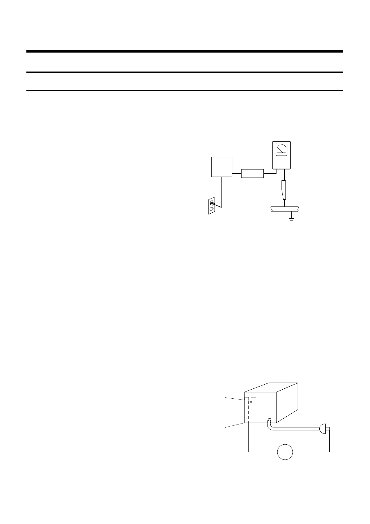
(3) Leakage Current Hot Check-With the instrument
completely reassembled, plug the AC line cord
directly into a 120V AC outlet. (Do not use an isolation transformer during this test.) Use a leakage
current tester or a metering system that complies
with American National Standards institute (ANSI)
C101.1 Leakage Current for Appliances and
Underwriters Laboratories (UL) 1270 (40.7). With
the instrument’s AC switch first in the ON position
and then in the OFF position, measure from a
known earth ground (metal water pipe, conduit,
etc.) to all exposed metal parts of the instrument
(antennas, handle brackets, metal cabinets, screwheads, metallic overlays, control shafts, etc.), especially any exposed metal parts that offer an electrical return path to the chassis.
Any current measured must not exceed 0.5mA.
Reverse the instrument power cord plug in the outlet and repeat the test. See Fig. 1-1.
Any measurements not within the limits specified
herein indicate a potential shock hazard that must
be eliminated before returning the instrument to
the customer.
Fig. 1-1 AC Leakage Test
(4) Insulation Resistance Test Cold Check-(1) Unplug
the power supply cord and connect a jumper wire
between the two prongs of the plug. (2) Turn on the
power switch of the instrument. (3) Measure the
resistance with an ohmmeter between the
jumpered AC plug and all exposed metallic cabinet
parts on the instrument, such as screwheads,
antenna, control shafts, handle brackets, etc. When
an exposed metallic part has a return path to the
chassis, the reading should be between 1 and 5.2
megohm. When there is no return path to the chassis, the reading must be infinite. If the reading is
not within the limits specified, there is the possibility of a shock hazard, and the instrument must be
repaired and rechecked before it is returned to the
customer. See Fig. 1-2.
Fig. 1-2 Insulation Resistance Test
(READING SHOULD
NOT BE ABOVE
0.5mA)
EARTH
GROUND
DEVICE
UNDER
TEST
TEST ALL
EXPOSED METER
SURFACES
2-WIRE CORD
ALSO TEST WITH
PLUG REVERSED
(USING AC ADAPTER
PLUG AS REQUIRED)
LEAKAGE
CURRENT
TESTER
Antenna
Terminal
Exposed
Metal Part
ohm
ohmmeter

Precautions
1-2 Samsung Electronics
2) Read and comply with all caution and safety related notes on or inside the cabinet, or on the chassis.
3) Design Alteration Warning-Do not alter or add to
the mechanical or electrical design of this instrument. Design alterations and additions, including
but not limited to, circuit modifications and the
addition of items such as auxiliary audio output
connections, might alter the safety characteristics of
this instrument and create a hazard to the user. Any
design alterations or additions will make you, the
servicer, responsible for personal injury or property
damage resulting therefrom.
4) Observe original lead dress. Take extra care to
assure correct lead dress in the following areas:
(1) near sharp edges, (2) near thermally hot parts (be
sure that leads and components do not touch thermally hot parts), (3) the AC supply, (4) high voltage,
and (5) antenna wiring. Always inspect in all areas
for pinched, out-of-place, or frayed wiring, Do not
change spacing between a component and the
printed-circuit board. Check the AC power cord for
damage.
5) Components, parts, and/or wiring that appear to
have overheated or that are otherwise damaged
should be replaced with components, parts and/ or
wiring that meet original specifications.
Additionally, determine the cause of overheating
and/or damage and, if necessary, take corrective
action to remove any potential safety hazard.
6) Product Safety Notice-Some electrical and mechanical parts have special safety-related characteristics
which are often not evident from visual inspection,
nor can the protection they give necessarily be
obtained by replacing them with components rated
for higher voltage, wattage, etc. Parts that have special safety characteristics are identified by shading,
an ( )or a ( )on schematics and parts lists. Use
of a substitute replacement that does not have the
same safety characteristics as the recommended
replacement part might create shock, fire and/or
other hazards. Product safety is under review continuously and new instructions are issued whenever appropriate.

Precautions
Samsung Electronics 1-3
1-2 Servicing Precautions
CAUTION : Before servicing units covered by this
service manual and its supplements, read and follow
the Safety Precautions section of this manual.
Note : If unforseen circumstances create conflict
between the following servicing precautions and any
of the safety precautions, always follow the safety precautions. Remember: Safety First.
1-2-1 General Servicing Precautions
(1) a. Always unplug the instrument’s AC power cord
from the AC power source before (1) re-moving
or reinstalling any component, circuit board,
module or any other instrument assembly, (2)
disconnecting any instrument electrical plug or
other electrical connection, (3) connecting a test
substitute in parallel with an electrolytic capacitor in the instrument.
b. Do not defeat any plug/socket B+ voltage inter-
locks with which instruments covered by this
service manual might be equipped.
c. Do not apply AC power to this instrument and
/or any of its electrical assemblies unless all
solid-state device heat sinks are correctly installed.
d. Always connect a test instrument’s ground lead
to the instrument chassis ground before connecting the test instrument positive lead. Always
remove the test instrument ground lead last.
Note : Refer to the Safety Precautions section ground
lead last.
(2) The service precautions are indicated or printed on
the cabinet, chassis or components. When servicing, follow the printed or indicated service precautions and service materials.
(3) The components used in the unit have a specified
flame resistance and dielectric strength.
When replacing components, use components
which have the same ratings. Components identified by shading, by( ) or by ( ) in the circuit diagram are important for safety or for the characteristics of the unit. Always replace them with the exact
replacement components.
(4) An insulation tube or tape is sometimes used and
some components are raised above the printed
wiring board for safety. The internal wiring is
sometimes clamped to prevent contact with heating components. Install such elements as they
were.
(5) After servicing, always check that the removed
screws, components, and wiring have been installed correctly and that the portion around the
serviced part has not been damaged and so on.
Further, check the insulation between the blades of
the attachment plug and accessible conductive
parts.
1-2-2 Insulation Checking Procedure
Disconnect the attachment plug from the AC outlet
and turn the power ON. Connect the insulation resistance meter (500V) to the blades of the attachment
plug. The insulation resistance between each blade of
the attachment plug and accessible conductive
parts(see note) should be more than 1 Megohm.
Note : Accessible conductive parts include metal panels, input terminals, earphone jacks, etc.

Precautions
1-4 Samsung Electronics
1-3 ESD Precautions
Electrostatically Sensitive Devices (ESD)
Some semiconductor (solid state) devices can be damaged easily by static electricity.
Such components commonly are called Electrostatically Sensitive Devices(ESD). Examples of typical ESD
devices are integrated circuits and some field-effect
transistors and semiconductor chip components. The
following techniques should be used to help reduce
the incidence of component damage caused by static
electricity.
(1) Immediately before handling any semiconductor
component or semiconductor-equipped assembly,
drain off any electrostatic charge on your body by
touching a known earth ground. Alternatively,
obtain and wear a commercially available discharging wrist strap device, which should be
removed for potential shock reasons prior to applying power to the unit under test.
(2) After removing an electrical assembly equipped
with ESD devices, place the assembly on a conductive surface such as aluminum foil, to prevent electrostatic charge buildup or exposure of the assembly.
(3) Use only a grounded-tip soldering iron to solder or
unsolder ESD devices.
(4) Use only an anti-static solder removal devices.
Some solder removal devices not classified as
“anti-static” can generate electrical charges sufficient to damage ESD devices.
(5) Do not use freon-propelled chemicals. These can
generate electrical charges sufficient to damage
ESD devices.
(6) Do not remove a replacement ESD device from its
protective package until immediately before your
are ready to install it.(Most replacement ESD
devices are packaged with leads electrically shorted together by conductive foam, aluminum foil or
comparable conductive materials).
(7) Immediately before removing the protective ma-
terials from the leads of a replacement ESD device,
touch the protective material to the chassis or circuit assembly into which the device will be
installed.
CAUTION : Be sure no power is applied to the chassis or circuit, and observe all other safety precautions.
(8) Minimize bodily motions when handling unpack-
aged replacement ESD devices. (Otherwise harmless motion such as the brushing together of your
clothes fabric or the lifting of your foot from a carpeted floor can generate static electricity sufficient
to damage an ESD device).
Samsung Electronics
2-1
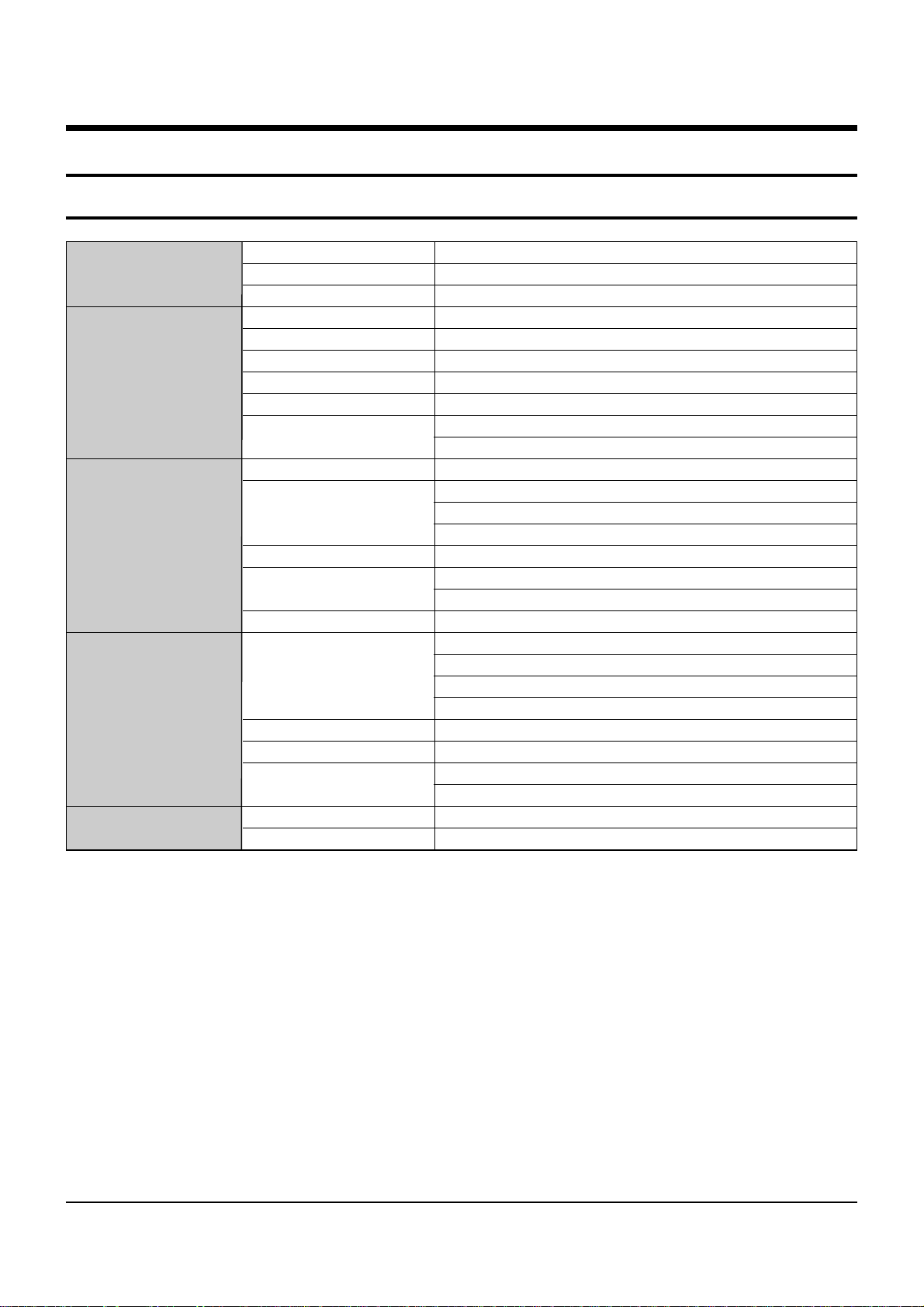
Type SMPS
Input voltage AC 100-240V~, 50/60 Hz
Fuse rating 250 V/T1.6AH
Input Frequency 50.5~858 MHz
Channel Bandwith 8 MHz
DEMODULATION QAM DVB-C
SYMBOL RATE MAX 7.252 Msps
Constellation 16, 32, 64, 128, 256 QAM
CABLE OUT RF LOOP-THROUGH OUTPUT for other
receiver or TV
System decoding MPEG-2 ISO/IEC 13818-2
Profile@Level (MP@HL(HD), MP@ML(SD))
H.264 ISO/IEC 14496-10
(MP@L3, MP@L4, HP@L4 up to 30 Mbps)
Resolution 1080i, 720p, 576p, (576i)
Video Output SD output (2 SCART (AV1,AV2), Composite RCA)
HD output (Component (YPBPR), HDMI)
Video Format 4:3(Normal) & 16:9 (Widescreen)
System decoding MPEG Audio-1 ISO/IEC 11172-3
(Layer1, Layer2)
MPEG Audio-2 ISO/IEC 13818-3
Dolby Digital (AC-3)
Audio mode Mono, Dual stereo, Joint stereo
Sampling Rate 32kHz, 44.1kHz, 48kHz, 96kHz
Audio output Analog output (L/R (RCA) 1 CH)
Digital output (S/PDIF(Optical))
Size (W x D x H) 351 x 227 x 60 mm
Weight (Net) 2.47Kg
Power Supply
Tuner
&
Demoduator
Video Decoder
Audio Decoder
Phisical Specifcation
2. Product Specification
2-1 Product Specification
Product Specification
2-2
Samsung Electronics
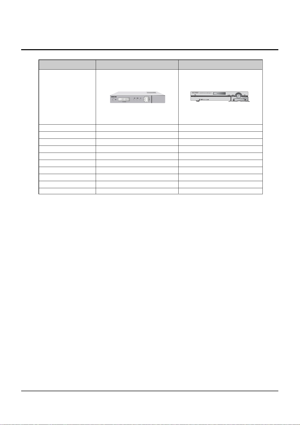
Model DCB-S300G DCB-H360R
Input Voltage AC 100-240V~,50/60Hz AC 100-240V~, 50/60 Hz
Size 270 X 200 X 45mm 351 X 227 X 60mm
Weight 1.195Kg 2.475Kg
Decoding Format Mpeg-2(ISO/IEC-13812-1) Mpeg-2(ISO/IEC-13818-3)
Video Format PAL PAL
Resolution 720p 1080i, 720p, 576p, (576i)
Audio Mode Dolby Decoding AC-3 Dolby Decoding AC-3
MPEG Audio Decoding MPEG 1 ISO/IEC 11172-1 layer 1 & 11 MPEG 1 ISO/IEC 11172-3
Down Mixed Chanel 2CH Chanel 2CH
Sampling Rates Supported 32, 44.1, 48 KHz 32kHz, 44.1kHz, 48kHz, 96kHz
Chassis
2-2 Chassis Product Specification
Product Specification
2-3
Samsung Electronics
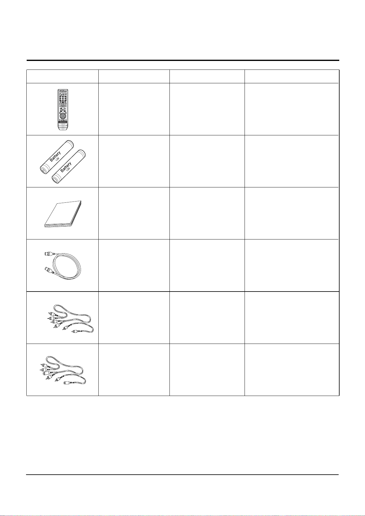
2-3 Option Product Specification
Description Fig Description Parts No Remark
Remote
Control
Batteries for
Remote Control
MF59-00286A
4301-001035
Model Standard
of DCB-H360R/XEN
S.N.A
Model Standard
of DCB-H360R/XEN
Model Standard
of DCB-H360R/XEN
Model Standard
of DCB-H360R/XEN
MF68-00397A
AC39-00017A
User’s Manual
RF Cable
Model Standard
of DCB-H360R/XEN
AC39-42001R
AV Cable
Model Standard
of DCB-H360R/XEN
MD39-00107A
RCA Cable

Product Specification
2-4
Samsung Electronics
MEMO
Samsung Electronics
3-1
3. Software Update
3-1 To Upgrade the Software
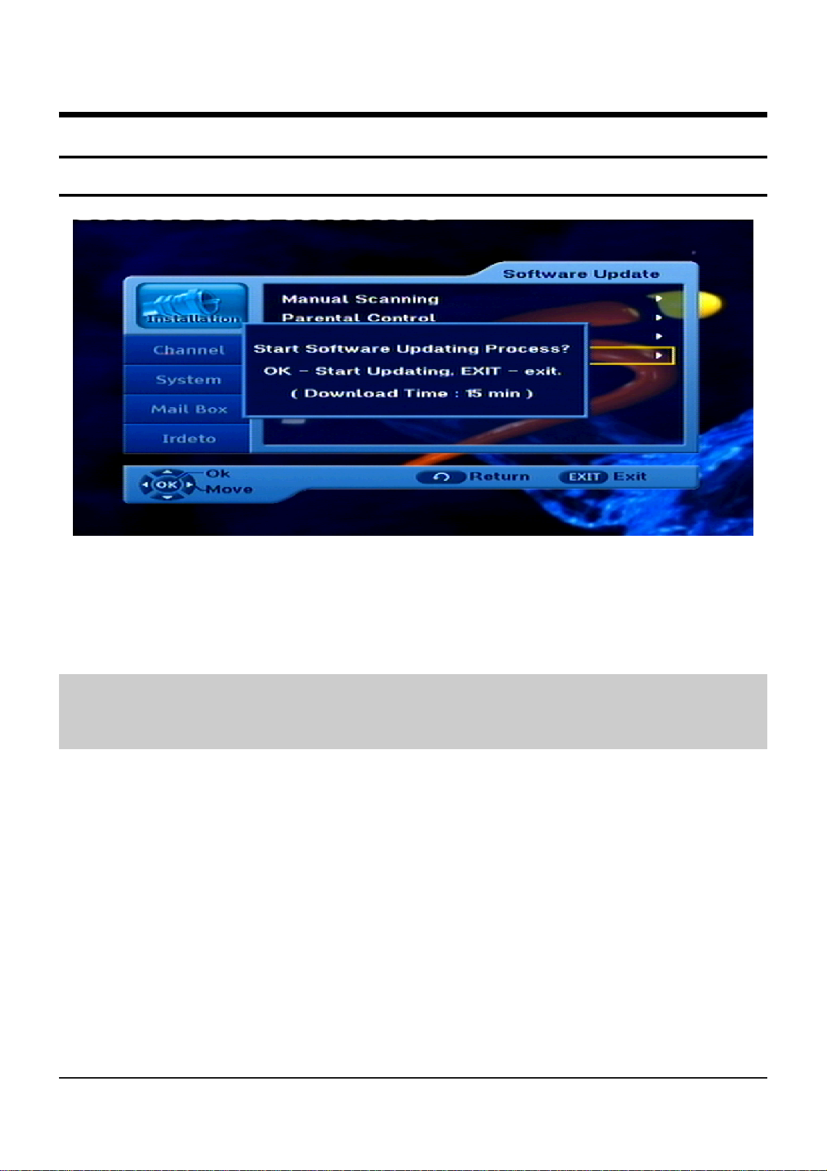
Fig. 3-1
To upgrade the software, place the cursor on Installation Software Update menu and press the OK key.
If new software is available, banner “Start Software Updating Process ?”
will be displayed. There is also information about estimated time of software download.
Press the OK key to confirm and start Software Updating process.
If there is the newest software on your STB “You don’t need to update software!” will be displayed.
Note : STB automatically reboots for software upgrading process. During the upgrading process, TV screen will remain
blank for approximately 10 minutes.
Window display at the STB front panel will show the progress. Service will be resumed automatically after
the upgrade is completed.

3-2
Software Update
Samsung Electronics
MEMO
Samsung Electronics 4-1
4. Disassembly and Reassembly
4-1 Cabinet and PCB
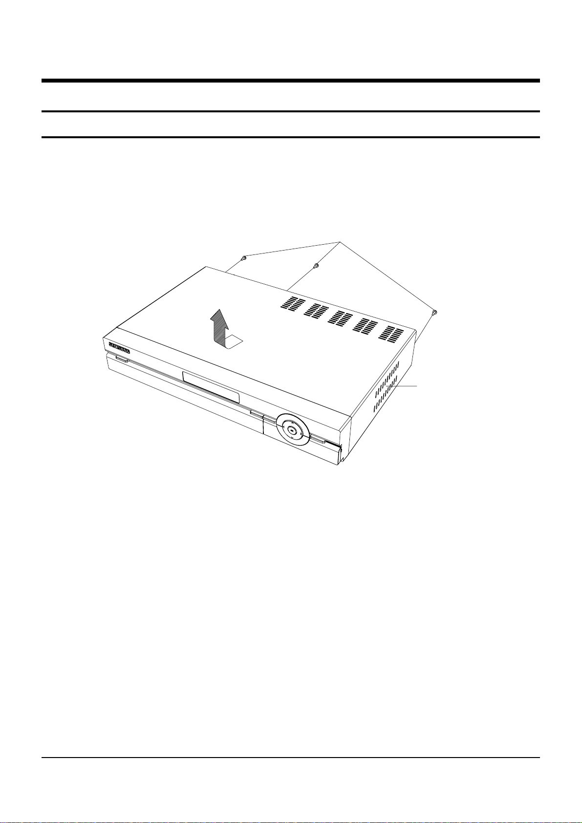
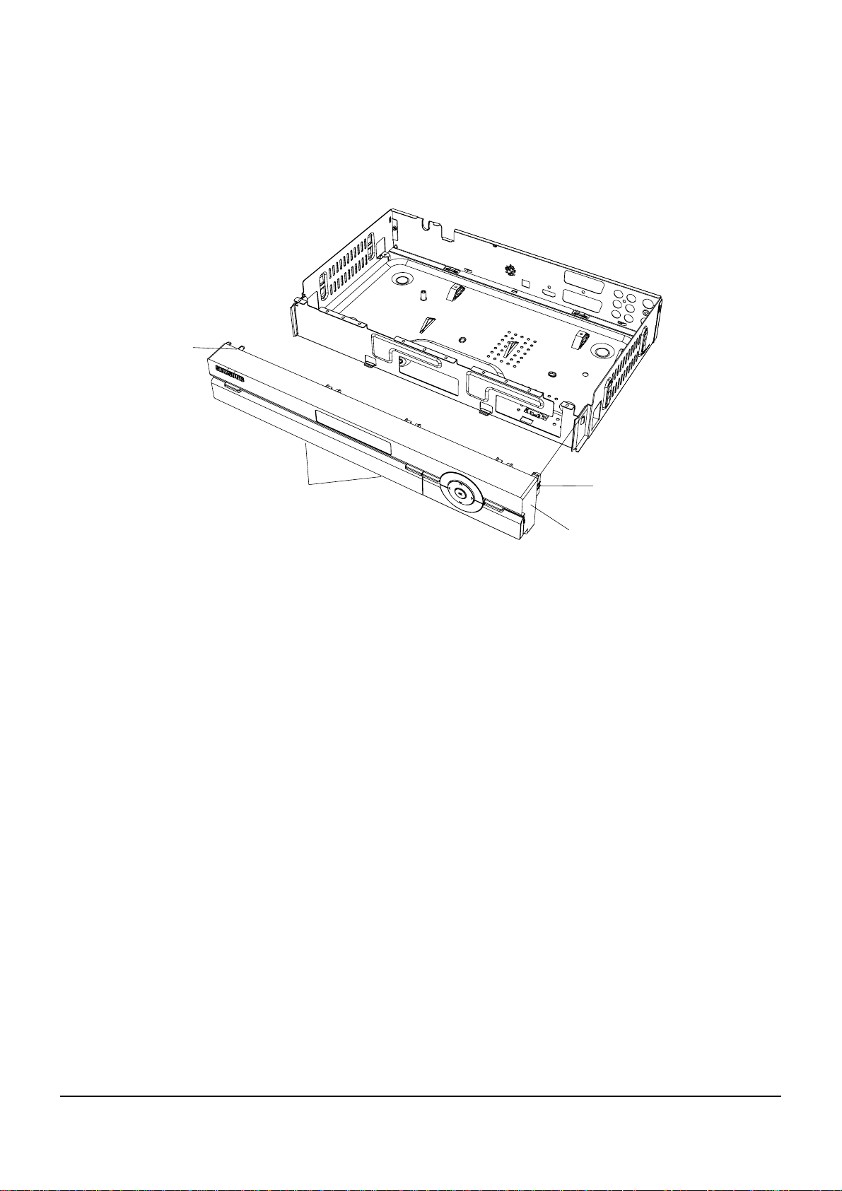
4-1-1 Top Cabinet Removal
1) Remove 3 Screws Œ the back Top Cabinet ´.
2) Lift up the Top Cabinet ´ in direction of arrow.
Fig. 4-1 Top Cabinet Removal
Π3 SCREWS
(3 X 8 B)
´ TOP CABINET
4-2
Disassembly and Reassembly
Samsung Electronics
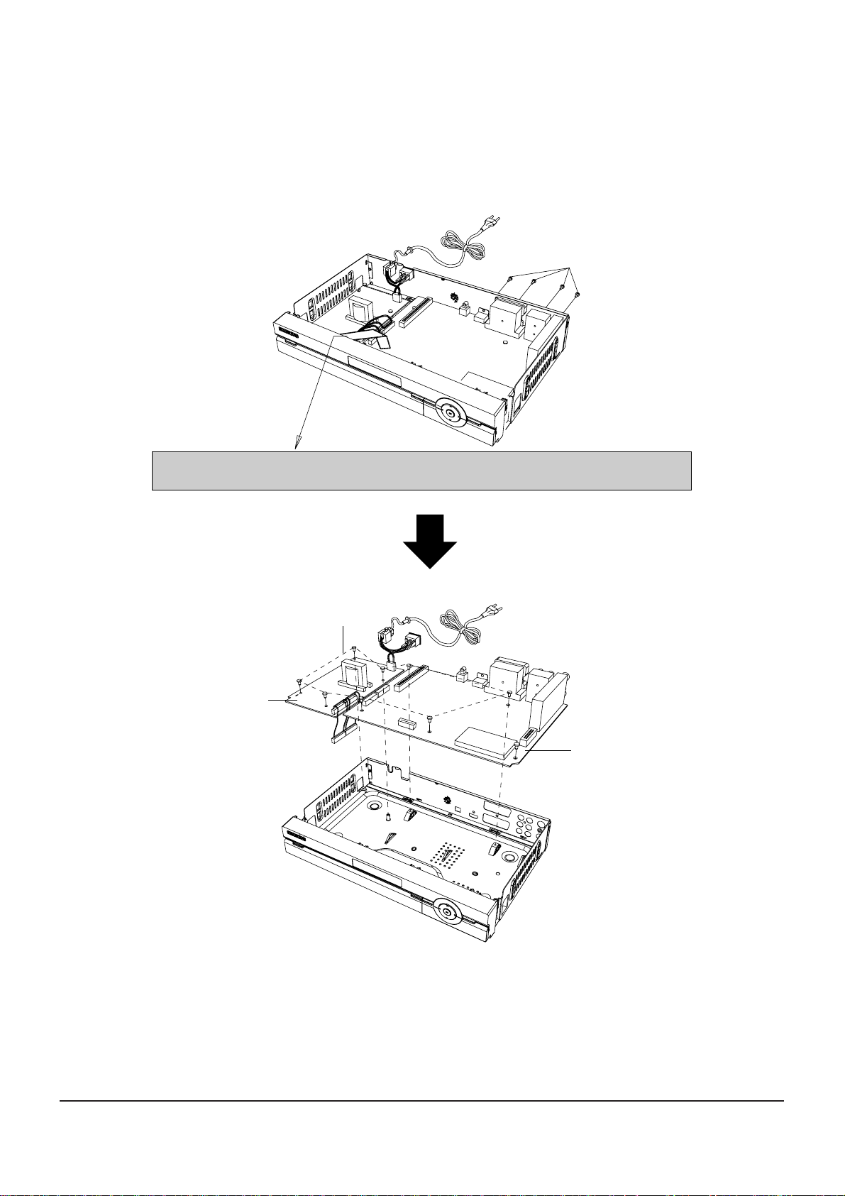
4 -1-2 Main PCB, S.M.P.S PCB Removal
1) Remove 12 Screws Œ, ´.
2) Lift up the Main PCB ˇ, S.M.P.S PCB ¨.
Fig. 4-2 Main PCB, S.M.P.S PCB Removal
CAUTION : After assemble Ass’y panel Front at Ass’y cabinet front assembly
That assemble cable-flat. (dissolution in reverse order)
Π4 SCREWS
(3 X 8 B)
¨ S.M.P.S PCB
´
8 SCREWS
(3 X 8 Y)
ˇ MAIN PCB
Disassembly and Reassembly
4-3Samsung Electronics
4-1-3 Ass’y Front-Cabinet Removal
1) Release 4 Hooks Œ, ´, ˇ and remove the Ass’y Front-Cabinet ¨.
Fig. 4-3 Ass’y Front-Cabinet Removal
Π1 HOOK
ˇ 2 HOOKS
´ 1 HOOK
¨ ASS'Y FRONT-CABINET
4-4
Disassembly and Reassembly
Samsung Electronics
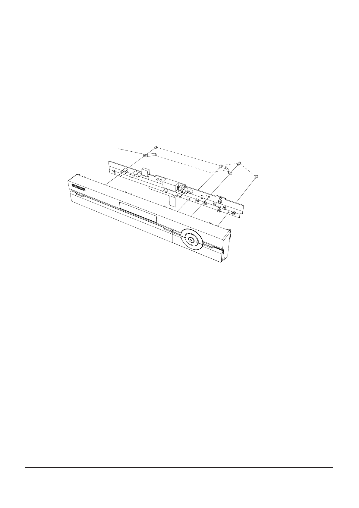
4-1-4 Front PCB Removal
1) Remove 4 Screws Œ.
1) Remove 2 PCB BRACKETS ´.
1) Remove FRONT PCB ˇ.
Fig. 4-4 Front PCB Removal
´ 2 PCB BRACKETS
Π4 SCREWS
(3 X 8 Y)
ˇ FRONT PCB
Samsung Electronics
5-1
5. Troubleshooting
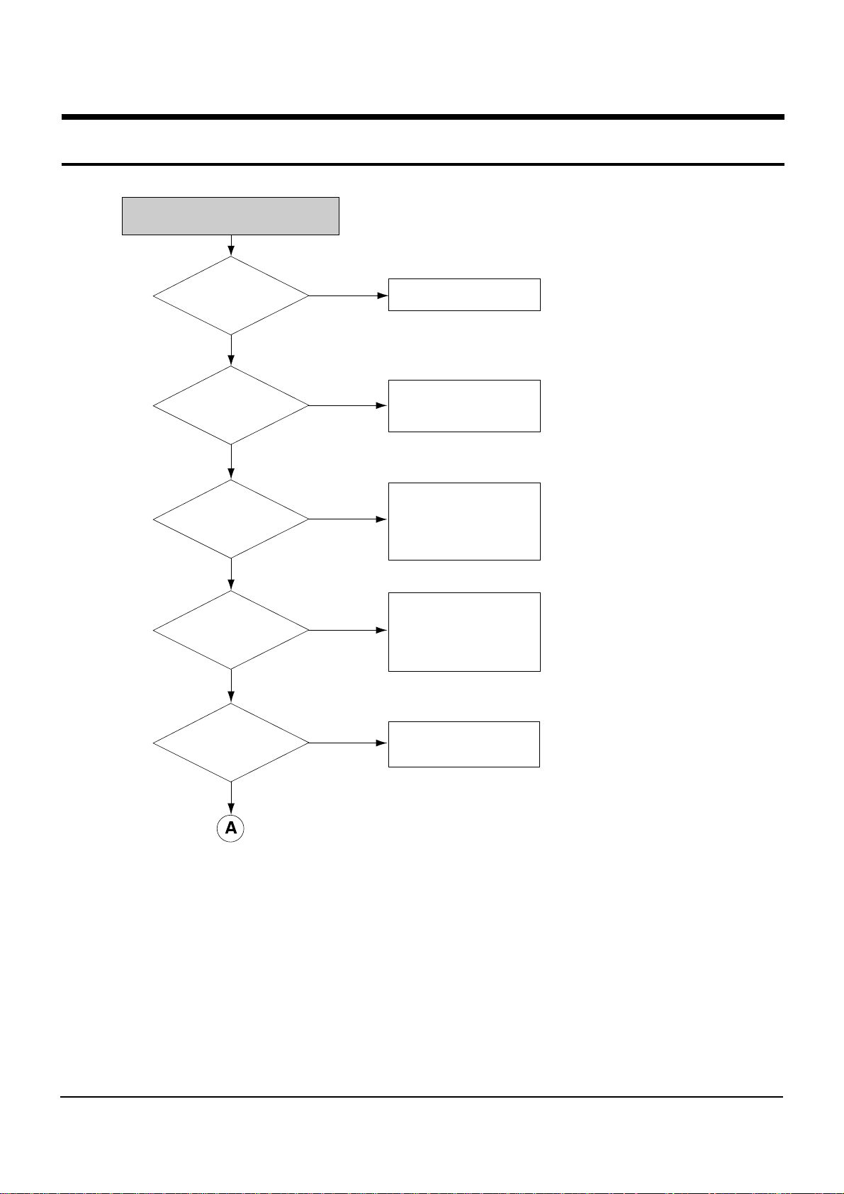
No Power Detected
Check the Power
Plug connection
Check the Voltage
at C2's both ends of AC
input voltage
Measure the
voltage of C39 1.4times
of input
Check the
voltage of Vcc for SMPS
controller
Check the
connection at several main
power
Check the shorting at
several main power
Connect Power Plug
Check F1(Fuse) "REMOVE"
and Change
• Check the Ri
(R1 : 2W 2.7Ω)
• Check the shoting of Q1
If the controller is
operating unstably or no
operation,change the U1
No
Yes
Yes
Yes
Yes
No
No
No
Yes
No
Troubleshooting
5-2
Samsung Electronics
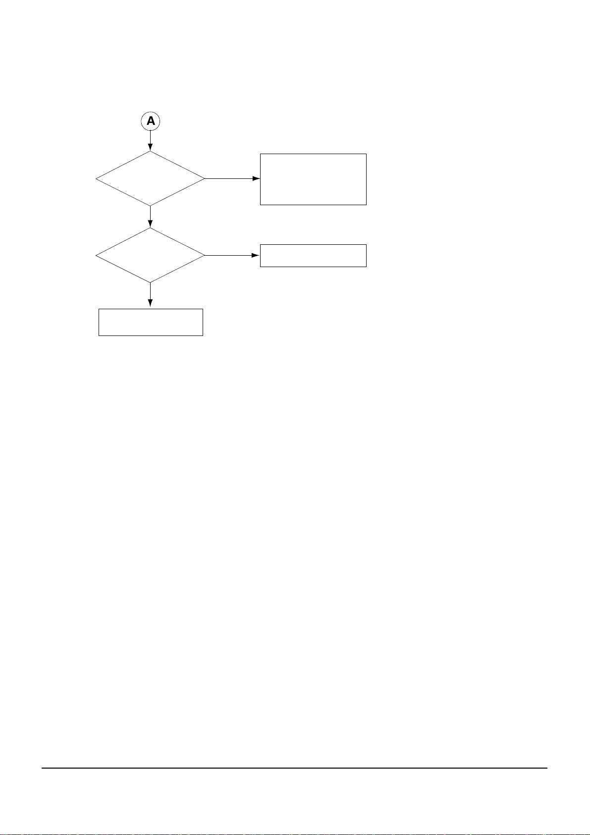
Check the existing
of pulse at pin10 of U5
• U5 pin8 voltage
• U5 pin12 PULSE
• Q3 EMITTER PUSE
Check the gate
pulse(pin1) of
Q13/Q14
Q17/Q18/Q10/Q16/Q12
PULSE
Connect between SMPS and
Main Power
No
Yes
Yes
No
Troubleshooting
5-3
Samsung Electronics
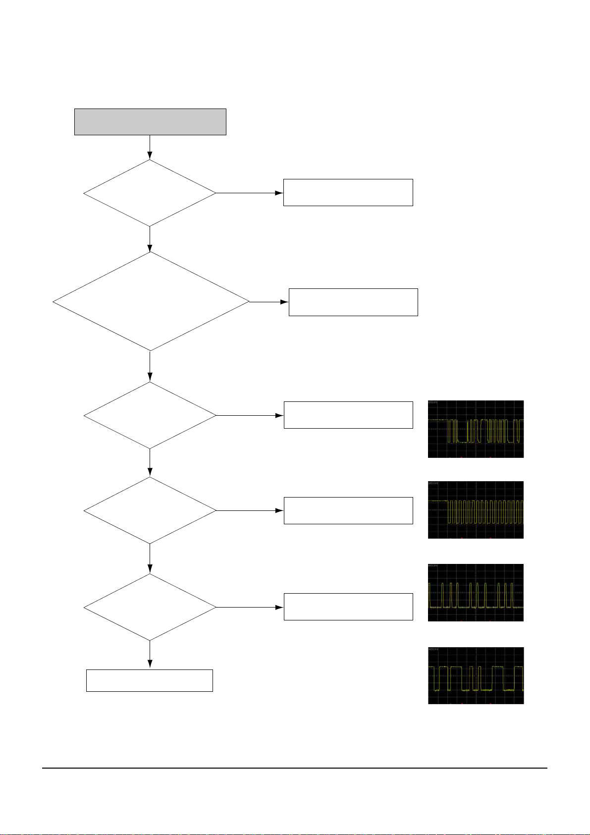
TV channel Missing
Antenna Cable is
connected well ?
Check I2C data bus of
Tuner 29,30 pin.
Data/clock signal OK?
Check TS & Clock pins
from 20pin to 28pin.
Data & clock OK?
Check serial registers'
condition of TS & control pins.
No problem ?
Connect Antenna cable.
Check tuner's(TM101) voltages.
5,11,12pin=5V,6pin=32V,14,15pin=3.3V
and 16pin(Reset)="High"
Check Voltage drive
circuit and repair trouble.
Check I2C bus line
between tuner and CPU.
Change for same spec tuner.
Correct resistors of
location(R107~R121).
Check HD Decoder "U25".
Tuner 29pin
Tuner 30pin
TS & Clock 20pin
TS & Clock 21~28pin
No
Yes
Yes
Yes
No
No
No
Yes
Yes
No
Troubleshooting
5-4
5-4
Samsung Electronics
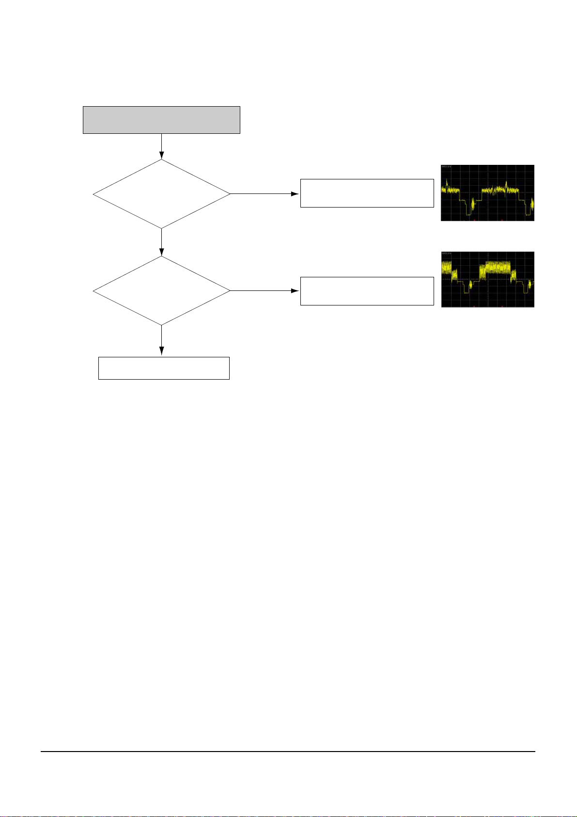
Composite Video signal Missing
(RCA Connector)
Check CVBS input
at 4pin of U1003 (HD Filter).
Check Failure mode of U25(S5H2110).
Check CVBS output
1,2 pin of U1003 (HD Filter).
Check Failure mode of
U1003(LA73060V)
Check Failure mode
of J1002(RCA Connector)
4pin of U1003
1,2 pin of U1003
No
Yes
Yes
No
Troubleshooting
5-5
Samsung Electronics
Check Failure mode
of J1401 SCARTConnector)
Composite Video signal Missing
(SCART Connector)
Check CVBS input
at 4pin of U1003
(HD Filter).
Check Failure mode
of U25(S5H2110).
Check CVBS output
1,2 pin of U1003
(HD Filter).
Check Failure mode
of U1003(LA73060V)
Check CVBS input
43 pin of U1301
(AV Switch).
Check R1306,C1318,R1056
R1035,C1056,C1009
Check CVBS output
30,34 pin of U1301
(AV Switch).
Check Failure mode
of U1301(MAX4397S)
4pin of U1003
1,2 pin of U1003
43 pin of U1301]
30,34 pin of U1301
Yes
Yes
No
No
Yes
Yes
No
No
Troubleshooting
5-6
Samsung Electronics
Check Failure mode
of J1002(RCA Connector)
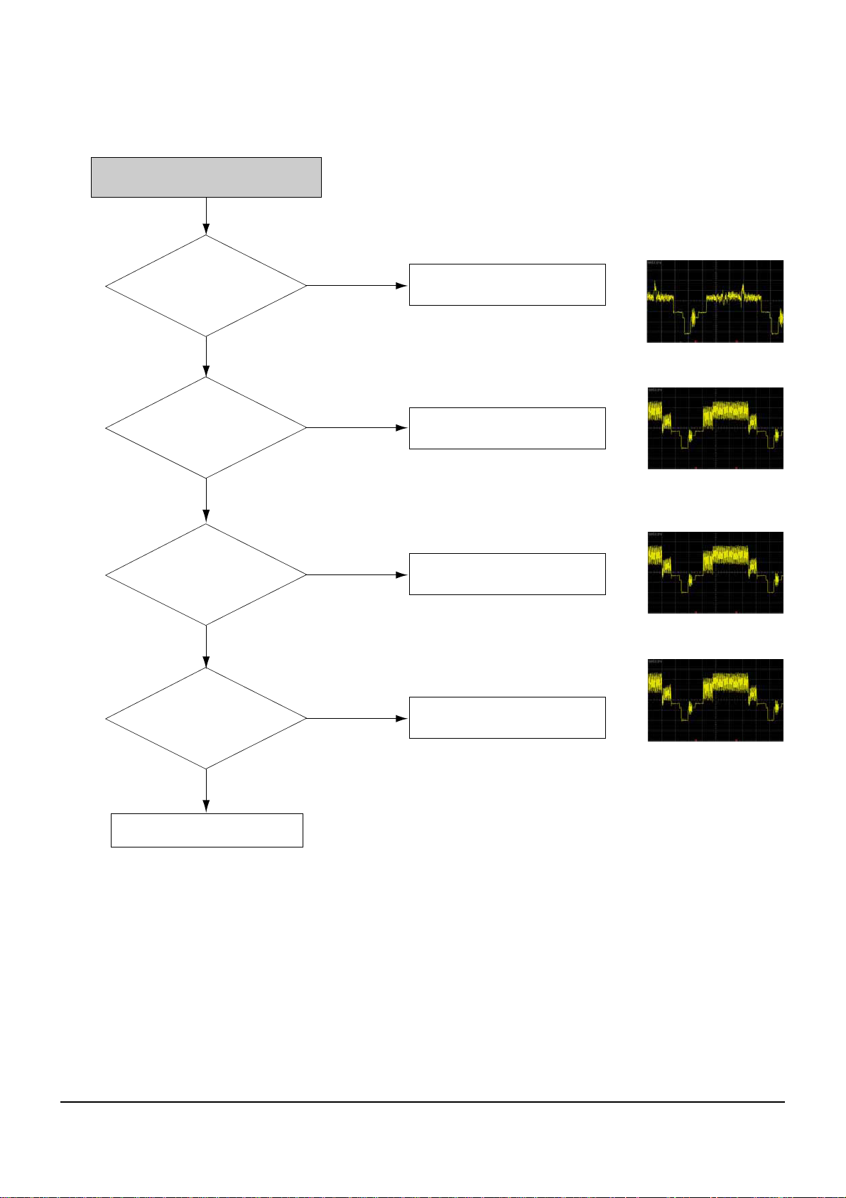
Component Signal Missing
Check Y/Pb/Pr mode or not.
Change to YPbPr mode.
Check Y/Pb/Pr signal at
C1024,C1025,C1026.
Check Failure mode of U25(S5H2110).
Check Y/Pb/Pr signal at
C1027,C1029,C1030.
Check Failure mode
of U1003(LA73060V).
Check Y/Pb/Pr signal at
R1006, L1008, R1010,
L1009, R1005, L1007
Check
Y: R1006, L1008
Pb: R1010, L1009
Pr: R1005, L1007
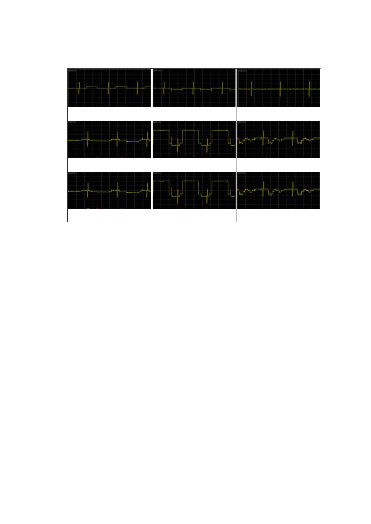
Refer to Wave pattern image
of Table 5-1
Refer to Wave pattern image
of Table 5-1
Refer to Wave pattern image
of Table 5-1
No
Yes
Yes
Yes
Yes
No
No
No
Troubleshooting
5-7
Samsung Electronics
<Table 5-1>
Y/Pb/Pr Signal at C1024
Y/Pb/Pr Signal at C1027
Y/Pb/Pr Signal at L1008
Y/Pb/Pr Signal at C1025
Y/Pb/Pr Signal at C1029
Y/Pb/Pr Signal at L1009
Y/Pb/Pr Signal at C1026
Y/Pb/Pr Signal at C1030
Y/Pb/Pr Signal at L1007
Troubleshooting
5-8
Samsung Electronics
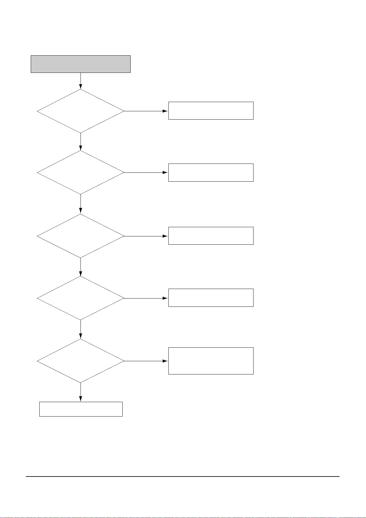
Check RGB-Jack Connection
(STB<->TV).
RGB Signal Missing (SCART Jack)
Check DTV Output Select
switch RGB mode or not.
Change to RGB mode.
Check R/G/B signal
at C1024,C1025,C1026.
Check Failure mode of U25(S5H2110).
Check R/G/B signal
at R1012, R1014, R1016
Check Failure mode
of U1003(LA73060V).
Check R/G/B signal
at Pin31,32,33 of U1301
Check Failure mode
of U1301(MAX4397S)
Check R/G/B signal at
Pin7,11,15 of SCART Jack
Check R1403,R1404,R1405,
R1409,R1410,R1411
C1405,C1406,C1407
Refer to Wave pattern image
of Table 5-2
Refer to Wave pattern image
of Table 5-2
Refer to Wave pattern image
of Table 5-2
Refer to Wave pattern image
of Table 5-2
No
Yes
Yes
Yes
No
No
No
Yes
Yes
No
Troubleshooting
5-9
Samsung Electronics
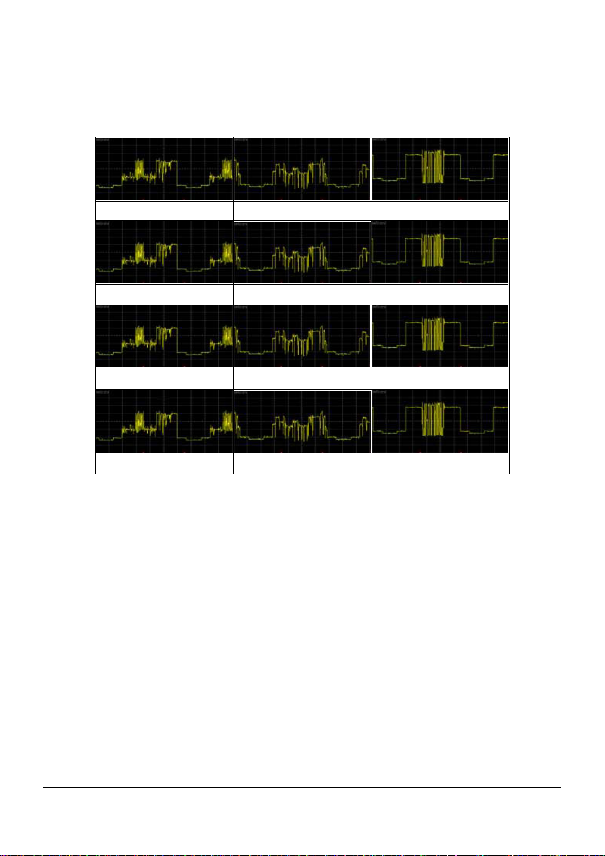
R/G/B Signal C1024 R/G/B Signal C1025
R/G/B Signal C1026
R/G/B Signal R1012-R R/G/B Signal R1014-G
R/G/B Signal R1016-B
R/G/B Signal U1301-31_R R/G/B Signal U1301-32_G
R/G/B Signal U1301-33_B
R/G/B Signal SCRAT-15_R R/G/B Signal SCRAT-11_G
R/G/B Signal SCRAT-7_B
<Table 5-2>
Troubleshooting
5-10
Samsung Electronics
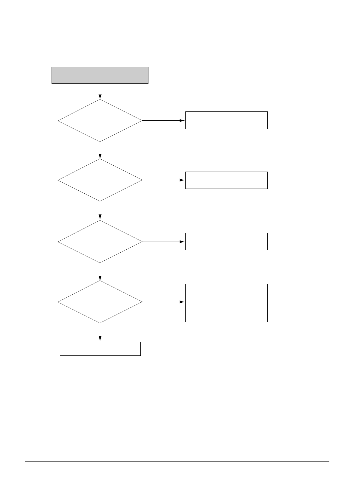
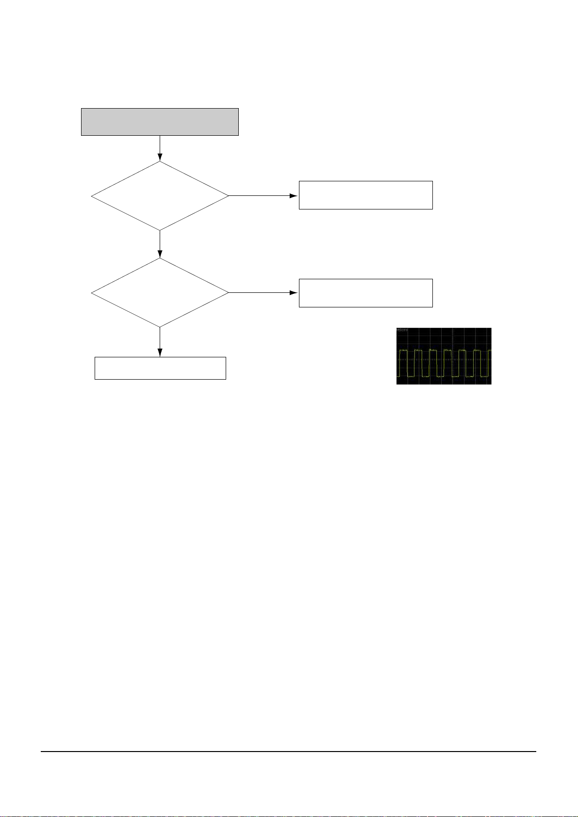
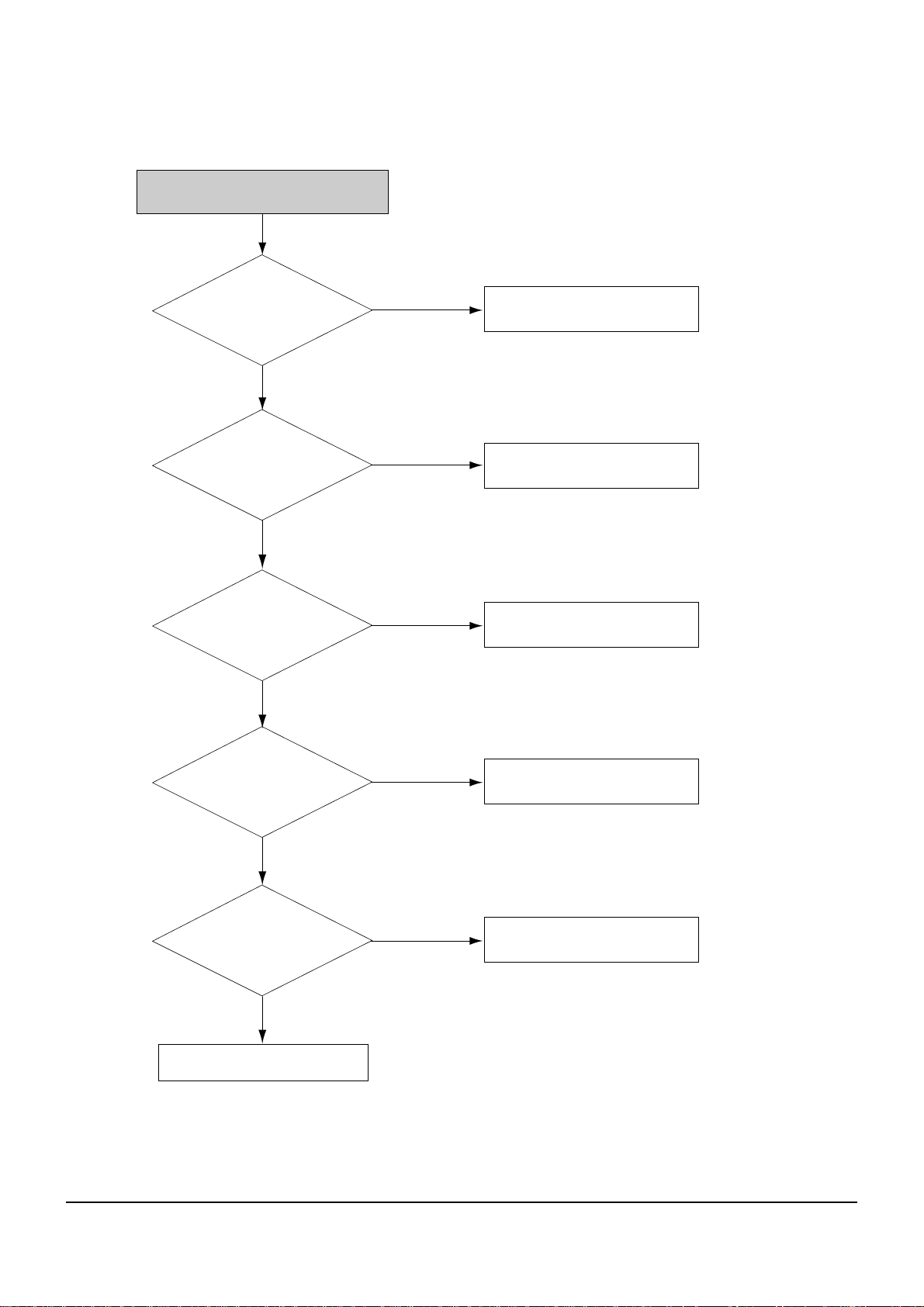
SPDIF Output Missing (Optical)
Check +5V
at Pin2 of J1001 ?
Check +5V Drive
Check Digital Audio signal
at R1019
Check Failure mode
of U25(S5H2110).
Check J1001 Optical Jack
Failure mode
Digital Audio signal at R1019
No
Yes
Yes
No
Troubleshooting
5-11
Samsung Electronics
RCA Sound Output Missing
Check Digital Audio Data at
R1159, R1160, R1161, R1162
Check Failure mode
of U25(S5H2110).
Check +5V at Pin6
of U1002
Check +5V Drive
Check Analog Audio
output at Pin7,8pins of
U1002,
Check U1002
Failure mode.
Check Audio signal at
1,7pins of U1001
Check U1001 Failure mode and
application circuit
Check Audio signal at
C1011, C1017
Check Q1040, 1041 of Audio mute
Check Failure mode
of J1002(RCA Connector)
Refer to Wave pattern image
of Table 5-3
Refer to Wave pattern image
of Table 5-3
Refer to Wave pattern image
of Table 5-3
Refer to Wave pattern image
of Table 5-3
No
Yes
Yes
Yes
No
No
No
Yes
Yes
No
Troubleshooting
5-12
Samsung Electronics
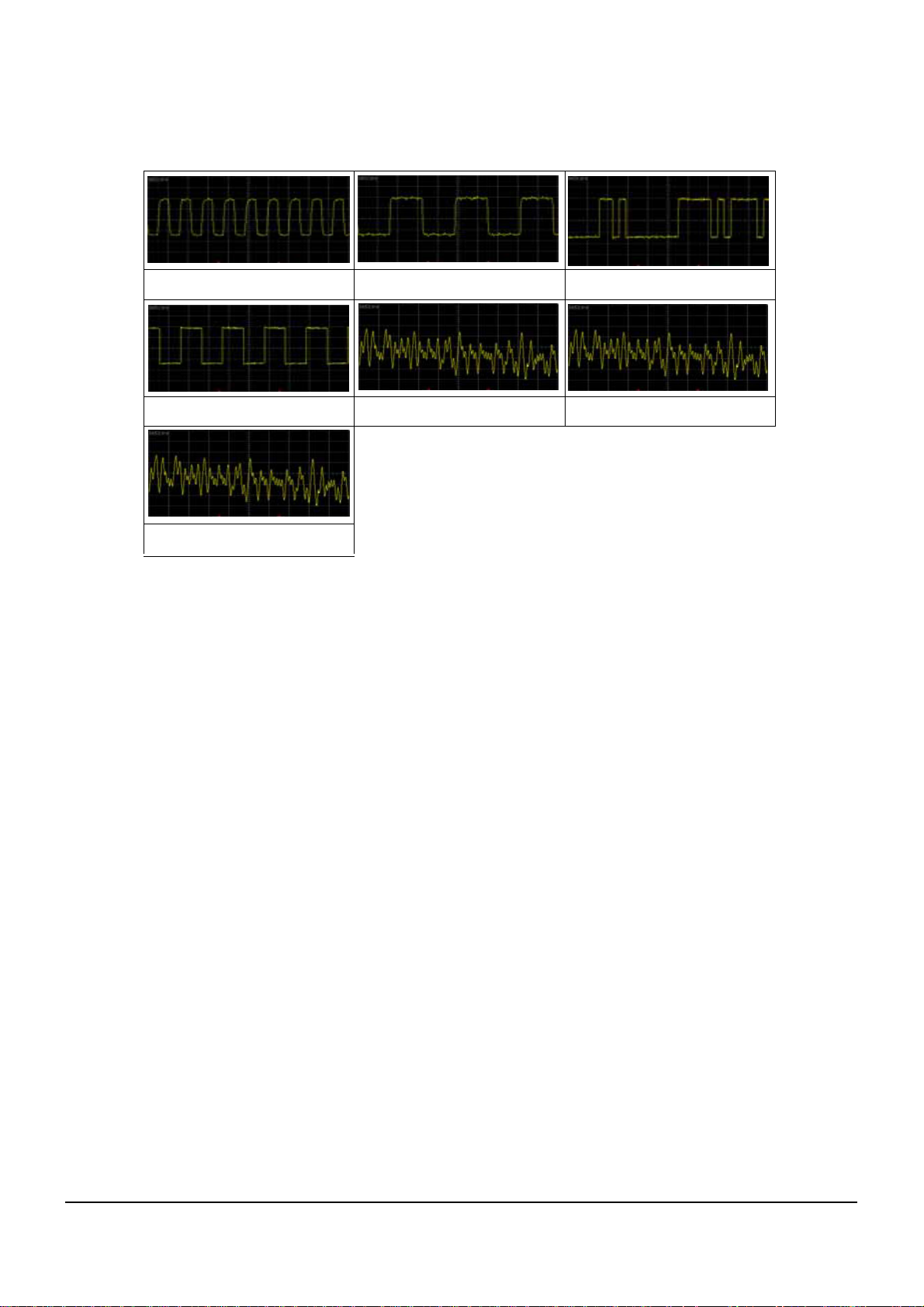
<Table 5-3>
Digital Audio Data at R1159 Digital Audio Data at R1160
Digital Audio Data at R1161
Digital Audio Data at R1162 Analog Audio output at Pin7,8pins
Audio signal at 1,7pins
Audio signal at C1011, C1017
 Loading...