

Samsung DCB-H360R User Manual [da]

DCB-H360R
Instructions for use
GB
REV. 1.3
DIGITAL CABLE HD RECEIVER
HDMI Connection GuideHDMI Connection Guide
Please connect STB to TV with HDMI cable, and then turn on the STB. It might be necessary to
switch the TV off and on again when:
1) HDMI-related setup was changed via OSD menu
2) HDMI cable was disconnected and then connected again
Some of TV models might not work properly with HDMI connection. In which case it is
recommended that HDMI audio option (see page 29) be changed, or component (YPbPr)
connection be used instead(see page 7).
Correct Disposal of This Product
(Waste Electrical & Electronic Equipment)
(Applicable in the European Union and other European
countries with separate collection systems)
This marking shown on the product or its literature,
household wastes at the end of its working life. To prevent possible harm
to the environment or human health from uncontrolled waste disposal,
please separate this from other types of wastes and recycle it responsibly
to promote the sustainable reuse of material resources.
Household users should contact either the retailer where they purchased
this product, or their local government office, for details of where and
how they can take this item for environmentally safe recycling.
Business users should contact their supplier and check the terms and
conditions of the purchase contract. This product should not be mixed
with other commercial wastes for disposal.
indicates that it should not be disposed with other

SAFETY INSTRUCTIONS
This STB has been manufactured to satisfy international safety standards.
Please read the following recommended safety precautions carefully.
MAINS SUPPLY: AC 100-240V~, 50/60Hz
OVERLOADING: Do not overload wall outlets, extension cords or adapters as this
can result in fire or electrical shock.
LIQUIDS: Keep liquids away from the STB.
CLEANING: Before cleaning, disconnect the STB from the wall socket.
Use a cloth lightly dampened with water(no solvents) to clean the
exterior.
VENTILATION: Do not block the STB ventilation holes. Ensure that free airflow is
maintained around the STB. Never store the STB where it is exposed
to direct sunlight or near heating equipment e.g. a radiator.
Never stack other electronic equipment on top of the STB.
Place the STB at least 30mm from the wall. Need at least 10mm from
the top and both side of the STB for ventilation.
DCB-H360R
GB
ATTACHMENTS: Do not use any attachment that is not recommended by the
manufacturer; it may cause a hazard or damage the equipment.
SERVICING: Do not attempt to service this product yourself.
Any attempt to do so will make the warranty invalid.
Refer all servicing to a qualified service agent.
LIGHTNING: If the STB is installed in an area subject to intense lightning activity,
protection devices for the STB mains connector and modem telephone
line are essential. The individual manufacturer’s instruction for
safeguarding other equipment, such as TV set, Hi-Fi, etc., connected
to the STB must also be followed during lightning storms.
GROUNDING: CATV cable MUST BE EARTHED.
The grounding system must comply with local regulations.
NNoottee : Dispose the used batteries at designated place for environment protection.
To disconnect the apparatus from the mains, the plug must be pulled out from the
mains socket, therefore the mains plug shall be readily operable.
GB-1

DCB-H360R
TECHNICAL OVERVIEW
What are SDTV and HDTV ?
SDTV
SDTV is a digital TV format that provides a high quality picture at resolutions that can be
displayed on standard TV sets (see more on resolutions later in this chapter).
HDTV
HDTV is a digital TV format that provides the highest quality picture at resolutions that can be
displayed on computer monitors and HDTV-ready TV displays (see more on resolutions later in
this chapter).
Resolution
Resolution refers to the number of pixels on the screen. The higher the resolution, the better
the visual quality.
Digital broadcasts are classified into HD and SD grades according to the visual quality. In
general, HD (High Definition) grade supports resolutions of 1920x1080i and 1280x720p and an
aspect ratio of 16:9 for both ATSC and DVB standards.
SD (Standard Definition) grade supports resolutions of 720x480p and 720x480i for the ATSC
standard, and supports resolutions of 720x576p and 720x576i for the DVB standard.
SD grade usually supports an aspect ratio of 4:3. However, it may differ depending on the
region.
DVB-C ( Cable Digital Video Broadcasting)
Digital video broadcasting - cable (DVB-C) is European standard DVB for digital broadcasting
transmission via cable. DVB-C system provide audio/video digital transmission through mpeg-2
format and utilize QAM modulation system.
DVB-C standard has been developed so that a digital broadcasting signal can be sent through
VHF/UHF channels. The advantages of this standard are relatively protected environment with
respect to distortion and signal path attenuation so a higher signal to noise ratio can be
achieved and no negative effect from multipath so higher order modulation schemes can be
implemented.
GB-2
DIGITAL CABLE

TECHNICAL OVERVIEW
Aspect ratio
In addition to resolution, HDTV is also defined by the aspect ratio of its broadcasts.
Aspect ratio means the shape of the screen as defined by the ratio of the screen’s width to its
height. For analog TV and SDTV, the aspect ratio is 4 units wide by 3 units high (usually written
4:3). This is the familiar shape of conventional TVs — slightly wider than they are tall.
For HDTV broadcasts, the aspect ratio is 16:9 (nearly twice as wide as it is tall).
This is, not coincidentally, more like the shape of movies shown in theaters.
This makes HDTV an ideal format for broadcasting and viewing movies on a TV.
But what happens if you are watching a nearly square-shaped 4:3 broadcast on a rectangular
16:9 TV, or vice-versa? The HD Receiver allows you to choose from a variety of screen formats
to help you deal with those scenarios.
Dolby®Digital 5.1
Dolby Digital 5.1 provides 5 discrete channels of digital audio information for use by A/V receivers
capable of decoding the 5.1 channel signal.
The audio signals are broken into left-front, center, right-front, left-rear, right-rear and a
low-frequency effects channel (designed for subwoofers).
The result when connected to a compatible Dolby Digital 5.1 channel A/V receiver and speaker
setup is a home theater experience that provides much of the dynamic range, 360-degree
imaging, and sonic excitement of a real theater.
To take full advantage of the Dolby Digital 5.1 capabilities of the HD Receiver, you will need a
Dolby Digital 5.1 compatible A/V receiver connected to the HD Receiver through the Dolby Digital
Optical jack.
AC-3 is a sound encoding/decoding technology developed in 1987 for movie theatres and means
an AC-3 bit stream. AC-3 is used synonymously with Dolby Digital nowadays.
DCB-H360R
GB
HDMI (High Definition Multimedia Interface)
HDMI is an interface to enable the digital transmission of video and audio data with just
a single connector.Using HDMI the receiver transmits a digital video and audio signal
and displays as a vivid picture on a TV having an HDMI input jack.
GB-3

DCB-H360R
CONTENT
Safety Instructions . . . . . . . . . . . . . . . . . . . . . . . . . . . . . . . . . . . . . 1
Technical Overview . . . . . . . . . . . . . . . . . . . . . . . . . . . . . . . . . . . . . 2
Content . . . . . . . . . . . . . . . . . . . . . . . . . . . . . . . . . . . . . . . . . . . . . . 4
General Features . . . . . . . . . . . . . . . . . . . . . . . . . . . . . . . . . . . . . . . 5
Connecting Your “STB” . . . . . . . . . . . . . . . . . . . . . . . . . . . . . . . . . 6
Description . . . . . . . . . . . . . . . . . . . . . . . . . . . . . . . . . . . . . . . . . . . 12
Front Panel . . . . . . . . . . . . . . . . . . . . . . . . . . . . . . . . . . . . . . . . . . 12
Rear Panel. . . . . . . . . . . . . . . . . . . . . . . . . . . . . . . . . . . . . . . . . . . 13
Remote Control Unit. . . . . . . . . . . . . . . . . . . . . . . . . . . . . . . . . . . . 14
Basic Functions. . . . . . . . . . . . . . . . . . . . . . . . . . . . . . . . . . . . . . . . 16
Operating The Receiver . . . . . . . . . . . . . . . . . . . . . . . . . . . . . . . . . 22
Main Menu . . . . . . . . . . . . . . . . . . . . . . . . . . . . . . . . . . . . . . . . . . . . 22
1. Installation . . . . . . . . . . . . . . . . . . . . . . . . . . . . . . . . . . . . . . . . 22
1.1 Manual Scanning . . . . . . . . . . . . . . . . . . . . . . . . . . . . . . . 23
1.2 Parental Control . . . . . . . . . . . . . . . . . . . . . . . . . . . . . . . . 23
1.3 Reset to Factory Defaults . . . . . . . . . . . . . . . . . . . . . . . . . 24
1.4 Software Update . . . . . . . . . . . . . . . . . . . . . . . . . . . . . . . . 24
2. Channel . . . . . . . . . . . . . . . . . . . . . . . . . . . . . . . . . . . . . . . . . . 24
2.1 Update List . . . . . . . . . . . . . . . . . . . . . . . . . . . . . . . . . . . . 24
2.2 Favorite Channels . . . . . . . . . . . . . . . . . . . . . . . . . . . . . . . 25
2.3 Set Channel Lock . . . . . . . . . . . . . . . . . . . . . . . . . . . . . . . 25
3. System . . . . . . . . . . . . . . . . . . . . . . . . . . . . . . . . . . . . . . . . . . . 26
3.1 Language Selection. . . . . . . . . . . . . . . . . . . . . . . . . . . . . . 26
3.2 OSD Settings . . . . . . . . . . . . . . . . . . . . . . . . . . . . . . . . . . 27
3.3 Media Settings . . . . . . . . . . . . . . . . . . . . . . . . . . . . . . . . . 28
3.4 Change PIN Code . . . . . . . . . . . . . . . . . . . . . . . . . . . . . . . 29
3.5 Timer Settings. . . . . . . . . . . . . . . . . . . . . . . . . . . . . . . . . . 29
3.6 System Information . . . . . . . . . . . . . . . . . . . . . . . . . . . . . . 30
4. Mail Box . . . . . . . . . . . . . . . . . . . . . . . . . . . . . . . . . . . . . . . . . . 30
5. Irdeto Menu. . . . . . . . . . . . . . . . . . . . . . . . . . . . . . . . . . . . . . . . 31
5.1 CA Status . . . . . . . . . . . . . . . . . . . . . . . . . . . . . . . . . . . . . 31
5.2 IRD Status . . . . . . . . . . . . . . . . . . . . . . . . . . . . . . . . . . . . 31
5.3 Loader Status . . . . . . . . . . . . . . . . . . . . . . . . . . . . . . . . . . 31
Available TV Manufacturer Numbers . . . . . . . . . . . . . . . . . . . . . . . 32
Troubleshooting . . . . . . . . . . . . . . . . . . . . . . . . . . . . . . . . . . . . . . . 38
Disposal . . . . . . . . . . . . . . . . . . . . . . . . . . . . . . . . . . . . . . . . . . . . . . 38
Technical Specifications. . . . . . . . . . . . . . . . . . . . . . . . . . . . . . . . . 39
GB-4
DIGITAL CABLE

1. USER SECTION
2. TUNER SECTION
GENERAL FEATURES
DIGITAL HD/SDTV BROADCASTING RECEPTION
SOFTWARE DOWNLOAD VIA NETWORK
ADVANCED ELECTRONIC PROGRAM GUIDE
MULTI LANGUAGE SUPPORTED FOR OSD
SUBTITLE & TELETEXT(OSD ) SUPPORTED
WITH MULTI LANGUAGE
FULL FUNCTION INFRARED REMOTE CONTROL UNIT
SCART OUTPUT
LOW POWER CONSUMPTION
4 FAVORITE LISTS
AUTO UPDATED EPG
PASS LOOP FOR RGB SIGNAL
15 TIMERS TO RESERVE PROGRAMS(EVENTS) FOR TURNING
ON/OFF
VHF, UHF BAND 50.5~858 MHz
MAX 7.252 Msps SYMBOL RATE
16~256 QAM Modulation Format
RF LOOP-THROUGH OUTPUT FOR OTHER RECEIVER OR TV
DCB-H360R
GB
3. VIDEO SECTION
4. AUDIO SECTION
DVB-C COMPLIANT
MPEG-2: HD(MP@HL), SD(MP@ML)
H.264: MP@L3, MP@L4, HP@L4 up to 30 Mbps
USER SELECTABLE OUTPUT FORMATS 1080i, 720p, 576p, (576i)
1~30 Mbps DATA RATE
SUPPORTS ASPECT RATIO 4:3(NORMAL) AND 16:9(WIDE SCREEN)
HDMI, COMPONENT, COMPOSITE, SCART
DOLBY DECODING
MPEG-1 AUDIO LAYER 1, LAYER 2
MPEG-2 AUDIO
MONO, DUAL, STEREO AND JOINT STEREO AUDIO MODE
32, 44.1 AND 48 kHz SAMPLING FREQUENCIES
VOLUME CONTROL AND MUTE FUNCTION THROUGH
REMOTE CONTROL
SPDIF DIGITALAUDIO OUTPUT
GB-5

DCB-H360R
YPbPrL
R
HDMI
ANT.IN
Y
P
B
PR
(OPTICAL)
AUDIO OUT
DIGITAL
HDMI OUT
RF OUT
VIDEO OUT
AUDIO OUT
VIDEO OUT
COMPONENT
AV1
(TV)
AV2
(EXT)
R
L
ANT.IN
Y
P
B
PR
(OPTICAL)
AUDIO OUT
DIGITAL
HDMI OUT
RF OUT
VIDEO OUT
AUDIO OUT
VIDEO OUT
COMPONENT
AV1
(TV)
AV2
(EXT)
R
L
CONNECTING YOUR “STB”
Connecting the receiver cable system
ANT.IN Connection
After installing your cable system, connect the
coaxial cable to “ANT.IN” terminal marked at the
rear of the STB.
All cable connectors should be finger tightened;
do not use any kind of wrench while tightening
connectors. The cable should be 75ohm
impedance coaxial cable.
Set-Top Box Rear Panel
RF OUT Connection
To facilitate the user using analog receiver
to view analog channels, STB has
been provided with a loop through terminal
marked as “RF OUT”.
Connect the coaxial cable from this terminal
to the IF input terminal of your analog
receiver. Now by keeping the STB in
standby, you will be able to tune and view
analog channels from your analog receiver.
GB-6
Set-Top Box Rear Panel
DIGITAL CABLE

Connecting Your STB
ANT.IN
Y
P
B
PR
H
RF OUT
VIDEO OUT
AUDIO OUT
VIDEO OUT
COMPONENT
AV1
(TV)
AV2
(EXT)
R
L
YPbPrL
R
HDMI
ANT.IN
Y
P
B
PR
RF OUT
VIDEO OUT
AUDIO OUT
VIDEO OUT
COMPONENT
R
L
Connecting the Set-Top Box to a TV Set
Composite Connection
1. Connect the cable system to
the ANT.IN jack on the Set-Top
Box.
2. Connect the Video Cables.
Connect a Composite video cable between
the VIDEO OUT jacks on the Set-Top Box and
the TV INPUT jacks on the TV.
3. Connect the Audio Cables.
Connect an audio cable between the L/R
AUDIO OUT jacks on the Set-Top Box and the
L/R AUDIO IN jacks on the TV.
DCB-H360R
Set-Top Box Rear Panel
GB
Component Connection
1. Connect the cable system to
the ANT.IN jack on the Set Top Box
2. Connect the Video Cables.
YPBPR format :
Connect a Component video cable
between the VIDEO OUT jacks on the
Set-Top Box and the TV INPUT jacks on
the TV.
3. Connect the Audio Cables.
Connect an audio cable between the
L/R AUDIO OUT jacks on the Set-Top
Box and the L/R AUDIO IN jacks on the
TV.
Set-Top Box Rear Panel
GB-7

DCB-H360R
ANT.IN
Y
P
B
PR
(OPTICAL)
AUDIO OUT
DIGITAL
HDMI OUT
RF OUT
VIDEO OUT
AUDIO OUT
VIDEO OUT
COMPONENT
AV1
(TV)
AV2
(EXT)
R
L
YPbPrL
R
HDMI
REAR VCR
TV REAR PANEL
Scart Connection
1. Connect the cable system to
the ANT.IN jack on the Set-Top
Box.
2. Connect a Scart cable between
the VCR OUT jacks on VCR and the
Scart AV2 (EXT) jacks on the STB.
3, Connect Scart cable between AV1
(TV) jack on the STB and jack Scart
Input on the TV
Connecting Your STB
Set-Top Box Rear Panel
GB-8
DIGITAL CABLE
Y
P
B
PR
(OPTICAL)
AUDIO OUT
DIGITAL
HDMI OUT
AV1
(TV)
AV2
(EXT)
ON
HDMI
ANT.IN
Y
P
B
PR
(OPTICAL)
AUDIO OUT
DIGITAL
HDMI OUT
RF OUT
VIDEO OUT
AUDIO OUT
VIDEO OUT
COMPONENT
AV1
(TV)
AV2
(EXT)
R
L
Connecting Your STB
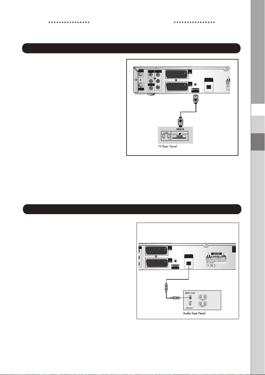
Connecting the Set-Top Box to a TV with a HDMI jack
Set-Top Box Rear Panel
1. Connect the cable system to
the ANT.IN jack on the Set-Top
Box.
2. Connect a HDMI cable
between the HDMI OUT jack
on the Set-Top Box and
the HDMI IN jack on the HDMI
device (TV , Monitor)
DCB-H360R
NNoottee : Depend on TV, HDMI
OUT may not operate properly.
GB
Connecting an Audio Component
There are many types of audio systems on the
market today.
A simplified illustration of an audio system is
shown to the right. For more information, see
your audio system owner’s manual.
For An optical digital audio input, connect the
audio system to the DIGITALAUDIO OUT
(OPTICAL) jack on the Set-Top Box.
Set-Top Box Rear Panel
GB-9

DCB-H360R
Connecting Your STB
Selecting the Resolution and the DTV Output Signal
You can select the appropriate video output for the connected TV or monitor mode.
To select the resolution:
● Select a resolution by using the RESOLUTION key on the
remote control and referring to the following table.
NNoottee : EXIT key at the front of the HD receiver also
operates as RESOLUTION key, when any OSD
is not displayed on the screen.
To select the video output signal:
● Select the output signal by using the VIDEO OUTPUT
key on the remote control and referring to the
following table.
RGB: Select the output signal by using the
VIDEO OUTPUT key on the remote control
referring to the following table.
BPR: Select YPBPR when the TV is connected to the
YP
Component (YP
BPR) and HDMI output port
of the HD receiver.
Resolution and Video Output
Video Out Available Resolution Output Status
Composite 576i Always output.
Scart 576i Scart output can be selected between RGB and
BPR
Component (YP
HDMI 1080i/720p/576p The 576i resolution is not supported.
NNoottee : Initial value is YP
) 1080i/720p/576p The 576i resolution is not supported.
BPR (1080i resolution) mode.
Composite.
GB-10
DIGITAL CABLE

Connecting Your STB
Setting Up TV Operations with the Remote Control
Enter the manufacturer number into the remote control to control the TV with the remote control (see
“Available TV Manufacturer Numbers” on pages 32~37).
1. Turn the TV on.
2. Point the remote control towards the TV.
3. Enter the TV manufacturer number by using the NUMERICAL keys while pressing the TV key.
E.g. For a Samsung TV, press 0, 0 and 1 in this order by using the NUMERICAL keys while
pressing the TV key.
4. When the TV is turned off or on, the configuration is finished.
TV functions that you can control with the remote control
Button key Function
TV STANDBY/ON
INPUT SEL
VOL+/CH /
MUTE
0~9
Press to turn the TV on or off.
Press to select an external input source for the TV.
Press to adjust the TV volume / Exclusive to the TV
Press to select a TV channel.
Press to mute the TV sound.
Press to select TV channel.
DCB-H360R
GB
NNoottee : 1.
2.
3.
4.
5.
There is a model that can only be turned on by pressing the numeric key ‘0’ on
the remote control.
TV models of other manufacturer that can be controlled with the remote control
are limited, and some functions may not work.
If you replace the remote control batteries or enter a new manufacturer number,
the previously configured TV manufacturer number is deleted.
When a connected device is an integrated TV model (VCR, DVDP), take care
when using the remote control because it may operate both of them
simultaneously.
If the configuration number does not work, try another number.
GB-11
DCB-H360R
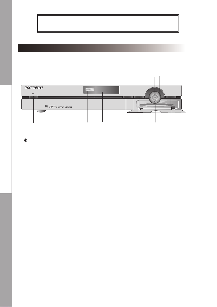
Front Panel
HIGH DEFINITION CABLE RECEIVER DCB-H360R
DESCRIPTION
GUIDE
MENU
6
7
EXIT
3
1
1. /I Turns the receiver operating or standby mode.
2. HDTV Displays the broadcasting status. When the STB detects a
3. Display Window Displays information about digital HDTV receiver.
4. GUIDE Press to display the on-screen Electronic Program Guide (EPG)
5. MENU Displays the main menu.
6. OK Selects highlighted items on Guide and Menu screens.
>
<
7. These arrow keys navigate in the on screen guide and menu
8. Card Slot Slot for Irdeto Smartcard.
9. EXIT Clears on-screen displays and returns to TV program viewing.
< >
HD Broadcasting signal, the HDTV logo lights.
system.
2
5
4
89
GB-12
DIGITAL CABLE
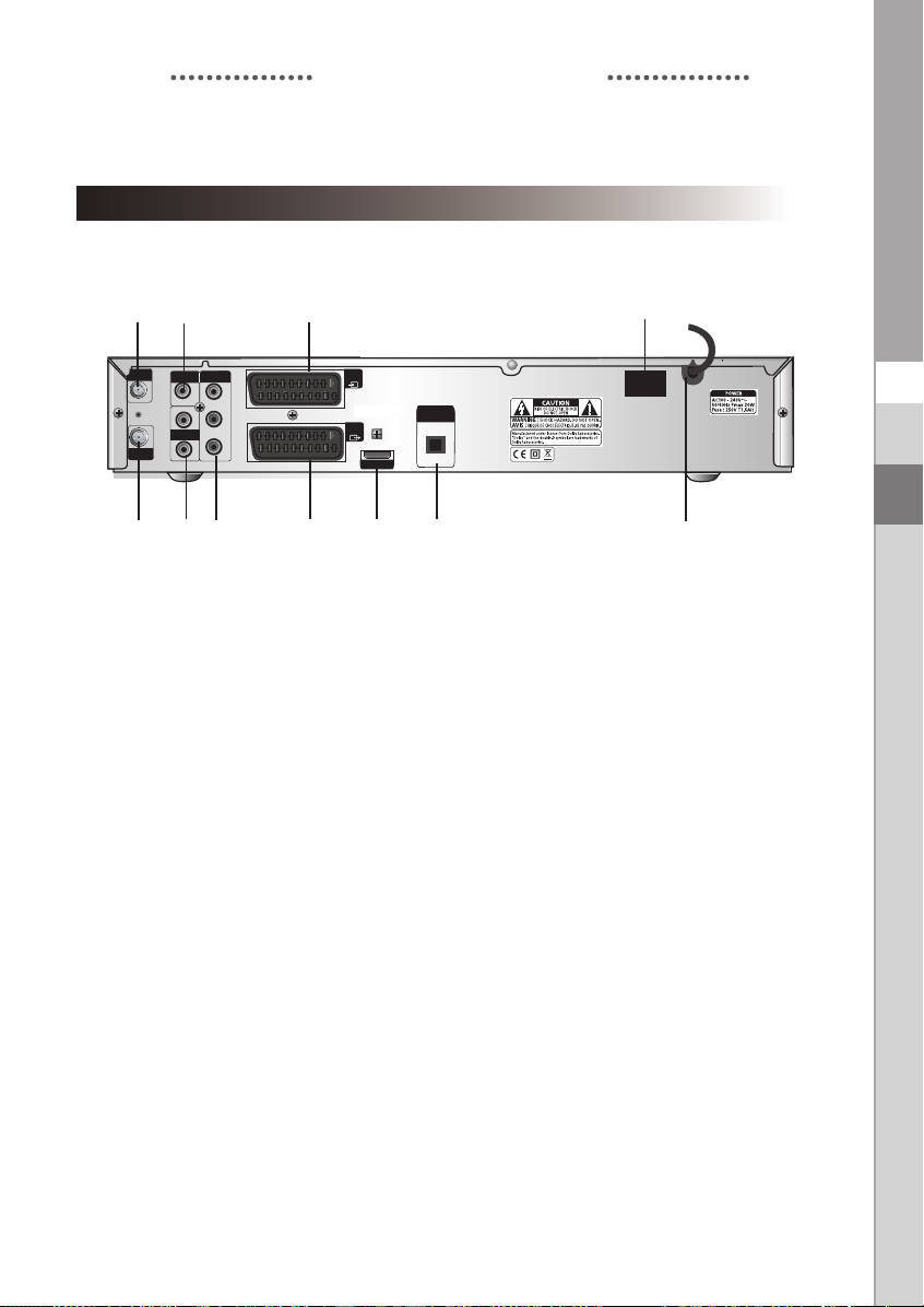
Rear Panel
DCB-H360R
DESCRIPTION
3
1
VIDEO OUT
L
AUDIO OUT
R
COMPONENT
VIDEO OUT
Y
P
B
PR
ANT.IN
RF OUT
245
7
AV2
(EXT)
DIGITAL
AV1
(TV)
6
AUDIO OUT
(OPTICAL)
HDMI OUT
89 11
10
ON
POWER
OFF
1. ANT.IN This port is connected to your cable system via a coaxial cable.
2. RF OUT Connects a TV or other receiver via a coaxial cable.
3. VIDEO OUT Connect to a TV, monitor or other external display device through the
Analog Video IN port.
4. AUDIO OUT Connect to a TV, audio receiver or other external device through the
analog Audio IN port.
5. COMP. VIDEO OUT Connect to a TV, monitor or other external display device through the
Component Video IN (YP
BPR). At this time, the VIDEO OUTPUT key
on the remote control has to be YPBPR mode.
6. AV1 (TV) This is used to connect to your TV.
7. AV2 (EXT) This is used to connect to your VCR, DVD or other receiver.
8. HDMI OUT Use the HDMI cable to connect this jack on your television for the best
quality picture.
9. DIGITAL AUDIO OUT Output for connection to a digital amplifier.
10. POWER SWITCH This is used to supply(ON) or interupt (OFF) the power.
11. POWER CORD Connect to the wall outlet of AC 100-240V, 50/60Hz.
GB
GB
GB-13

DCB-H360R
18
19
20
22
23
29
26
16
17
13
14
15
24
27
10
11
12
21
25
28
30
Remote Control Unit
NNoott ee : When inserting batteries,
make sure that the polarity(+/-) is correct.
DESCRIPTION
1.
TV (for TV exclusive use)
Switches the remote control mode to TV mode.
2.
STB
Switches the remote control mode to receiver mode.
3. STANDBY/ON
Turns the receiver operating or standby mode.
4. 0 ~ 9 NUMERICAL keys
Press the number keys to tune to a channel or to
enter numbers on menu screens.
5. FAV. CH
Use the key to switch between favorite lists.
6. ALT
Press once to select the soundtrack list and twice
to select video track list.
7. FREEZE
Press once to hold the picture, twice to release.
8.
AUDIO
Change the audio to the left, right or both channel.
9. CH. LIST
The scanned channel list appears.
10.Vol+ /Vol-
Adjust the volume level
11. MENU
Press to display the on-screen menus.
12. ¦
These keys are for moving the highlight bar for
selecting options on the menu.
13. GUIDE
Press to display the on-screen Electronic Program
Guide (EPG).
14. P.SIZE
Press to change the screen format according to
the screen aspect ratio and the input signal format.
15. COLOR (RED, GREEN, YELLOW, BLUE)
Use according to the instructions on the screen
when using a menu or guide screen.
GB-14
DIGITAL CABLE

DESCRIPTION
16
. RESOLUTION
Selects the output resolution format between 1080i, 720p, and 576p (576i) according to the
video input of the TV or monitor.
17. VIDEO OUPUT
Selects Video Output format between RGB and YPBPR according to the
video input of TV or monitor
18. TV STANDBY/ON
Turns the TV operating or standby mode.(for TV exclusive use)
19. INPUT SEL
Press to select the input source in the TV (for TV exclusive use)
20. PRE. CH
Turn to the previous channel.
21. SUBTITLE
Displays the subtitle on the screen.
22. TEXT
Displays the teletext OSD mode on the screen.
23. TIMER
This is used to reserve a program by EPG.
24. TV/RADIO
Toggles between the TV channel and Radio channel.
<
25. CH /
26. RETURN
27. MUTE
28. OK
29. INFO
30. EXIT
>
Press to change the channel
Press to return to the previous menu.
Mutes the audio
Press to confirm and save any data to the receiver in the menu system
Displays the program information in the screen. Press it once and basic information
appears.Press it twice and detailed information appears in the text box.
Clears on-screen displays and return to program viewing.
DCB-H360R
GB
GB
GB-15

DCB-H360R
BASIC FUNCTIONS
1. Display Screen
Before you can view the television program, you must perform the installation.
Therefore you will see only menu images at first.
After the television channels have been programmed, you will see the following picture(banner)
each time you switch channels:
! Parental Rating.
@ Favorite Group Number.
# Locked Channel.
$ Scramble Channel.
% Teletext.
● Press the INFO key in view mode.
● Select the channel by pressing NUMERICAL 0-9 or
^ Subtitle.
& Soundtrack.
* Mail.
( Announcement.
) Dolby Digital.
1 HD/SD
2 16:9/4:3
3 Program Progressive Bar.
keys and select the TV/RADIO key
to move to TV or Radio channel
You will also see this picture each time you change the channels.
When you press the TV/RADIO key on the remote control. TV and Radio program are toggled.
Detailed program information
● Press the INFO key three times while you are viewing a program
First you will see the banner described above.
After the INFO key is pressed in the second time, detailed information for current program can
be displayed on another banner, if there is more information. When this information is more than
one page, YELLOW and BLUE keys can be used for scroll up and down.
: This service depends on service provider.
NNoottee
GB-16
DIGITAL CABLE

BASIC FUNCTIONS
2. Volume Control
To control the volume level :
● Press
● Press the MUTE key to turn to silence mode.
● Press the MUTE key again or
NNoottee
the VOL- or VOL+
keys to adjust the volume level.
VOL- / VOL+
keys in order to cancel the mute function.
: HDMI sound is controlled by TV, not HD receiver.
3. Select Soundtrack
● Press the ALT key to see the soundtrack list.
● Press the
● The soundtrack service is not provided for every channel
and depends on the conditions the operator is in.
and OK key to select one.
DCB-H360R
GB
4. Select Videotrack
● Press the ALT key twice to see the videotrack list.
● Press the
● The videotrack service is not provided for every channel
and depends on the conditions the operator is in.
NNoottee : When you select AUTO in the selection window,
and OK key to select one.
operation will follow System Setup of main menu.
GB-17

DCB-H360R
BASIC FUNCTIONS
5. Channel List
● Press the CH LIST key while you are viewing a program.
● Select list by pressing the TV/RADIO key.
The icon behind the channel name symbolises scrambled
channel, and the icon behind the channel name shows
locked channel.
● Select the channel by pressing the
control.
● Press the OK key to watch that channel.
The colour key corresponds the following service list.
● YELLOW key : Favorites
● RED key : (Alphabetical) Sort
● Press the (Page Up/Dn) keys to move to next or previous page.
● Press the EXIT key to exit.
<
>
keys on the remote
5.1 Favorite Channel List
● Press the YELLOW key on the remote control to select the
group of favorite channel list.
● Press the YELLOW key to switch between favorite channel list
and channel list.
● Use the
keys to select a favorite group or a channel that
you want.
<
● Press the (Page Up/Dn) keys to move to next or previous page.
● Press the EXIT key to exit
>
5.2 Alphabetical Channel LIst
● Press the RED key on the remote control to select the
Alphabetical channel list.
● Press the RED key to switch between alphabetical channel list
and channel list.
● Use the
that you want.
● Press the EXIT key to exit.
keys to select a Alphabetical group or a channel
GB-18
DIGITAL CABLE

BASIC FUNCTIONS
6. Guide (EPG) Menu
EPG-Electronic Program Guide
The electronic program guide gives you information
for the channels.
NNoottee
: 1. This service depends on service provider.
2. After receiver recognized the GMT-time
from the signal which takes few seconds,
it can display correct EPG information.
● Press the GUIDE key while you are viewing a program.
● RED key is for moving back to the previous date.
● GREEN key is for moving to the next coming date.
● YELLOW key can be used for scroll up, if there is more information than one page.
● BLUE key can be used for scroll down, if there is more information than one page.
Time interval can be adjusted by press keys as followings on EPG screen:
1 key: 1 hour and 30 minutes 2 key: 30 minutes 3 key: 15 minutes
With the TV/RADIO key you can browse among the various programs lists.
● Select the channel by pressing the
● When the TIMER key on the remote control is pressed in the EPG screen, if the current channel
involves an event, timer is set immediately and the set timer is indicated on the EPG screen.
A program that has been set in this way is indicated on Timer Setting.
keys and press the OK key to watch this channel.
DCB-H360R
GB
GB-19

DCB-H360R
BASIC FUNCTIONS
7. Teletext OSD
When the current broadcasting program provides Teletext, press
the TEXT key once to see the current language list for Teletext in
order to get teletext in OSD regardless of TV type.
icon on the banner shows that Teletext is available on this
event(program). Even is displayed on the banner, Teletext
may not be available due to broadcasting.
● Press the EXIT key to exit.
NNoottee :
When the connected TV provides the Teletext
feature, this function is not supported.
The HD receiver does not support the Teletext
VBI function.
When the teletext application is active following keys can be used:
● NUMERICAL keys: 0.....9 are used to change main page.
Then in the left upper corner will be visible number of the main page. If the broadcasting
program provides this page after the moment (usually about 20s), this page will be visible.
●
keys are used to change main page , just (+1) for key and (-1) for key.
● ¦ keys are used to change Next/Previous subpage number.
Sometimes broadcaster send one or more subpages on one main page. To change sub-page
number just press ¦ or key, if subpages will be exist in STB memory then next/previous
subpage will be displayed.
8. Subtitle
When the current broadcasting program provides subtitle,
press the SUBTITLE key to see the current subtitle language list.
If subtitle is available on current program, is displayed on the
banner .
To change the subtitle language:
● Press the SUBTITLE key once to see the subtitle language
List.
● Use the
● Press the OK key and then the subtitle language you want is
displayed.
NNoottee : When you select AUTO in the selection window,
keys to select a subtitle language you want.
operation will follow System Setup of main menu.
GB-20
DIGITAL CABLE

BASIC FUNCTIONS
9. Audio Mode
You can choose a mode among left, right or stereo using the AUDIO
key.
To change the audio mode:
● Press the AUDIO key to select the left, right or stereo.
DCB-H360R
GB
GB
GB-21

DCB-H360R
OPERATING THE RECEIVER
Main Menu
After installing your cable system and STB with appropriate
connectors.
● Plug in the AC main power and switch on the receiver.
● Press the MENU key to bring up the main menu.
The following on screen display will appear:
The sub menu topics will be displayed.
For the sub-menus Installation, Channel , System, Mailbox and Irdeto
Before you begin with the “Installation” menu, you should check in the 3th menu
“System” whether all the information are applicable for you.
1. Installation
The menu provides settings for customizing, adding new services
and displaying the status of the receiver.
● Select “Installation” in the main menu to select the
sub menu.
● Enter the PIN Code.
If you have not entered your own PIN Code then the
PIN Code 0000 applies, which was set at the factory.
GB-22
DIGITAL CABLE

OPERATING THE RECEIVER
1.1 Manual Scanning
To tune-in new channels, the STB has been provided with
“Manual Scanning” where the channel data can be entered by
the user. After selecting the “Manual Scanning” from the
Installation Menu, the following screen will be displayed:
● Input the frequency of the channel you want to find.
● Input the Network ID of the channel you want to find.
Ask your cable operator.
● Select the Modulation of the channel you want to find.
You can select the value of 16, 32, 64, 128 and 256.
● Input the symbol rate of channel you want to find.
● After select option, press the OK key to start the scan
process.
● Press the EXIT key to exit the menu .
NNoottee
: When you see “NOT COMPLETE CHANNEL”, please scan again with following
instuction of service provider.
DCB-H360R
GB
GB
1.2 Parental Control
Parental rating protects your children from adult content.
This option is set in Installation Parental Control menu.
● Use the ¦keys to select age for your youngest child
then press the OK key to save this setting.
● All services which age grade is greater than set will be
blocked and request to enter the PIN Code.
● If you want blocked all services, select “ALL BLOCKED”.
● By default, all services are “UNBLOCKED”.
Please enter the PIN Code.
● This banner is shown if service which age grade is greater than
set in Parental Control menu. Enter four digits PIN Code to
hide this banner and show service content.
Factory PIN Code is 0000, and you can change it in
Change PIN Code menu.
● Press the EXIT key to exit the menu.
GB-23

DCB-H360R
OPERATING THE RECEIVER
1.3 Reset to Factory Defaults
This is to recover the Factory set values in case the user has
encountered some problems after changing any values of
channel data and others which may be in error.
The screen display will be as follows:
At the request window, if you press the OK key, the receiver
will be reset to factory default settings automatically.
NNoottee
: This causes your previous settings to be deleted!
All settings and information including channel data will
be deleted.
● Press the EXIT key to exit the menu .
1.4 Software Update
This option is enabled only if your cable provider sends software for your STB.
To upgrade the software, place the cursor on Installation Software Update menu and
press the OK key. If new software is available, banner “Start Software Updating Process ?”
will be displayed. There is also information about estimated time of software download.
Press the OK key to confirm and start Software Updating process.
If there is the newest software on your STB “You don’t need to update software !” will be
displayed.
NNoottee
: STB automatically reboots for software upgrading process. During the upgrading
process, TV screen will remain blank for approximately 10 minutes. Window display at
the STB front panel will show the progress. Service will be resumed automatically after
the upgrade is completed.
● Press the EXIT key to exit the menu.
2. Channel
The “Channel” menu has three functions:
Saving changes on channel list by select Update List and it
provides making four favourite lists and set channel lock,
as you want.
● Enter the PIN Code.
If you have not entered your own PIN Code, 0000 applies which
was set at the factory.
2.1 Update List
When some new channels will be transmitted to your cable
network, these channels would be shown on channel list
green colored. To save these channels, use Channel
List.
GB-24
Update
DIGITAL CABLE

OPERATING THE RECEIVER
2.2 Favorite Channels
You can immediately register the present channel to the desired
Favorite Group.
In addition, you can register a channel to multiple favorite groups.
● Select the desired Favorite Group(FAV1~FAV4) using the
FAV.CH key.
● Select the desired channel list using the or numeric keys
at the TV or RADIO list window.
● Press the RED key and then register the selected
channel at the Favorite Group.
● Then press the OK key for confirmation.
You can change TV list or Radio list by the TV/RADIO key and change favorite list
by the FAV.CH key.
● When you press the TV/RADIO key, TV list and Radio list are toggled.
● Press the FAV.CH key to select another favorite list.
● Press the EXIT key to exit the menu.
To delete channels from Favorite Group:
● Select a channel list to delete with the keys.
● Press the RED key to delete the selected channel from the favorite channels.
● Press the EXIT key to exit the menu.
NNoottee
: One favorite list can contain max 200 channels.
DCB-H360R
GB
GB
2.3 Set Channel Lock
● Select the TV or RADIO channel window by pressing the
¦keys.
● Focus the channel by pressing the keys.
● Select the channel lock by pressing the RED key.
● Press the OK key for confirmation.
This will lock the channel. Whenever you need to view the
channel, you will have to enter the PIN Code at the request
window.
To cancel the lock:
● Press the RED key again in order to cancel the lock.
● Press the EXIT key to exit the menu .
.
GB-25
 Loading...