

Samsung CL29Z40MQTXXAO User Manual

COLOR TELEVISION RECEIVER
Chassis : KS7D(N)_Timecop
Model : CL29Z40MQTXXAO
COLOR TELEVISION RECEIVER FEATURES
■
GREEN CRT
■
■
Turbo Voice
SERVICE
Manual
CL-29Z40MQ

This Service Manual is a property of Samsung Electronics Co.,Ltd.
Any unauthorized use of Manual can be punished under applicable
International and/or domestic law.
© Samsung Electronics Co., Ltd. May. 2006
Printed in Korea
AA82-03645A

Table of Contents
Chapter 1 Precaution
■ 1-1 Safety Precautions . . . . . . . . . . . . . . . . . . . . . . . . . . . . . . . . . . . . . . . . . . . . . . . . . . . . . . . . . . . 1-1
■ 1-2 Servicing Precautions . . . . . . . . . . . . . . . . . . . . . . . . . . . . . . . . . . . . . . . . . . . . . . . . . . . . . . . . 1-3
■ 1-3 Static Electricity Precautions . . . . . . . . . . . . . . . . . . . . . . . . . . . . . . . . . . . . . . . . . . . . . . . . . . . 1-4
■ 1-4 Installation Precautions . . . . . . . . . . . . . . . . . . . . . . . . . . . . . . . . . . . . . . . . . . . . . . . . . . . . . . . 1-5
Chapter 2 Product Specification
■ 2-1 Product Features . . . . . . . . . . . . . . . . . . . . . . . . . . . . . . . . . . . . . . . . . . . . . . . . . . . . . . . . . . . . 2-1
■ 2-2 Key Features . . . . . . . . . . . . . . . . . . . . . . . . . . . . . . . . . . . . . . . . . . . . . . . . . . . . . . . . . . . . . . . 2-2
■ 2-3 Specifications Analysis . . . . . . . . . . . . . . . . . . . . . . . . . . . . . . . . . . . . . . . . . . . . . . . . . . . . . . . . 2-3
■ 2-4 Accessories . . . . . . . . . . . . . . . . . . . . . . . . . . . . . . . . . . . . . . . . . . . . . . . . . . . . . . . . . . . . . . . . 2-4
Chapter 3 Alignment & Adjustment
■ 3-1 Service Instruction . . . . . . . . . . . . . . . . . . . . . . . . . . . . . . . . . . . . . . . . . . . . . . . . . . . . . . . . . . . 3-1
■ 3-2 How to Access Service Mode . . . . . . . . . . . . . . . . . . . . . . . . . . . . . . . . . . . . . . . . . . . . . . . . . . . 3-2
■ 3-3 Factory Data . . . . . . . . . . . . . . . . . . . . . . . . . . . . . . . . . . . . . . . . . . . . . . . . . . . . . . . . . . . . . . . . 3-3
■ 3-4 Service Adjustment . . . . . . . . . . . . . . . . . . . . . . . . . . . . . . . . . . . . . . . . . . . . . . . . . . . . . . . . . . 3-15
■ 3-5 Replacements & Calibration . . . . . . . . . . . . . . . . . . . . . . . . . . . . . . . . . . . . . . . . . . . . . . . . . . . . 3-17
Chapter 4 Exploded View & Part List
■ 4-1 CL29Z40MQTXXAO . . . . . . . . . . . . . . . . . . . . . . . . . . . . . . . . . . . . . . . . . . . . . . . . . . . . . . . . . 4-1
Chapter 5 Electrical Part List
■ 5-1 CL29Z40MQTXXAO . . . . . . . . . . . . . . . . . . . . . . . . . . . . . . . . . . . . . . . . . . . . . . . . . . . . . . . . . 5-1
Chapter 6 Troubleshooting
■ 6-1 Checkpoints by Error Mode . . . . . . . . . . . . . . . . . . . . . . . . . . . . . . . . . . . . . . . . . . . . . . . . . . . . 6-1
■ 6-2 Troubleshooting Procedures by Error Modes . . . . . . . . . . . . . . . . . . . . . . . . . . . . . . . . . . . . . . . 6-3
■ 6-3 Troubleshooting Procedures by ASS'Y . . . . . . . . . . . . . . . . . . . . . . . . . . . . . . . . . . . . . . . . . . . 6-4
■ 6-4 Troubleshooting by Blocks . . . . . . . . . . . . . . . . . . . . . . . . . . . . . . . . . . . . . . . . . . . . . . . . . . . . . 6-6
Chapter 7 Block Diagram
■ 7-1 Overall Block Diagram . . . . . . . . . . . . . . . . . . . . . . . . . . . . . . . . . . . . . . . . . . . . . . . . . . . . . . . . 7-1
■ 7-2 Partial Block Diagram . . . . . . . . . . . . . . . . . . . . . . . . . . . . . . . . . . . . . . . . . . . . . . . . . . . . . . . . . 7-2
Chapter 8 Wiring Diagram
■ 8-1 Overall Wiring . . . . . . . . . . . . . . . . . . . . . . . . . . . . . . . . . . . . . . . . . . . . . . . . . . . . . . . . . . . . . . . 8-1
■ 8-2 Pin Connection . . . . . . . . . . . . . . . . . . . . . . . . . . . . . . . . . . . . . . . . . . . . . . . . . . . . . . . . . . . . . . 8-2

Chapter 9 PCB Diagram
■ 9-1 Main Board . . . . . . . . . . . . . . . . . . . . . . . . . . . . . . . . . . . . . . . . . . . . . . . . . . . . . . . . . . . . . . . . . 9-1
■ 9-2 CRT Board . . . . . . . . . . . . . . . . . . . . . . . . . . . . . . . . . . . . . . . . . . . . . . . . . . . . . . . . . . . . . . . . . 9-3
Chapter 10 Schematic Diagram
■ 10-1 MAIN . . . . . . . . . . . . . . . . . . . . . . . . . . . . . . . . . . . . . . . . . . . . . . . . . . . . . . . . . . . . . . . . . . . . 10-1
■ 10-2 POWER . . . . . . . . . . . . . . . . . . . . . . . . . . . . . . . . . . . . . . . . . . . . . . . . . . . . . . . . . . . . . . . . . . 10-2
■ 10-3 Sound . . . . . . . . . . . . . . . . . . . . . . . . . . . . . . . . . . . . . . . . . . . . . . . . . . . . . . . . . . . . . . . . . . . . 10-3
Chapter 11 Operation Instruction & Installation
■ 11-1 Product Features and Functions . . . . . . . . . . . . . . . . . . . . . . . . . . . . . . . . . . . . . . . . . . . . . . . 11-1
Chapter 12 Disassembly & Reassembly
■ 12-1 Overall Disassembly & Reassembly . . . . . . . . . . . . . . . . . . . . . . . . . . . . . . . . . . . . . . . . . . . . 12-1
Chapter 13 Circuit Description
■ 13-1 Overall Block Description . . . . . . . . . . . . . . . . . . . . . . . . . . . . . . . . . . . . . . . . . . . . . . . . . . . . . 13-1
■ 13-2 Partial Block Description . . . . . . . . . . . . . . . . . . . . . . . . . . . . . . . . . . . . . . . . . . . . . . . . . . . . . 13-2
Chapter 14 Reference Information
■ 14-1 Option Byte . . . . . . . . . . . . . . . . . . . . . . . . . . . . . . . . . . . . . . . . . . . . . . . . . . . . . . . . . . . . . . . 14-1
■ 14-2 Technical Terms . . . . . . . . . . . . . . . . . . . . . . . . . . . . . . . . . . . . . . . . . . . . . . . . . . . . . . . . . . . . 14-2

1. Make sure all protective devices are properly installed
including non-metallic handles and compartment covers
when installing or re-installing the chassis or chassis
assemblies.
2. Make sure that no gaps exist between the cabinets for
children to insert their fingers in to prevent children from
receiving electric shocks. Gaps mentioned above include
ventilation holes of a too great magnitude between the
vaccum tube and the cabinet mask, and the improper
installation of the rear cabinet.
Errors may occur when the resistance is below 1.0 ㏁ or
over 5.2 ㏁.
In these cases, make sure that the device is repaired
before sending it back to the customer.
3. Check for Electricity Leakage (Figure 1-1)
Warning: Do not use an insulated transformer for checking the leakage. Use only those current leakage testers
or mirroring systems that comply with ANSIC 101.1 and
the Underwriter Laboratory's specifications (UL1410,
59.7).
Fig. 1-1 AC Leakage Test
4. A high voltage is maintained within the specified limits
using safety parts, calibration and tolerances. When
voltage exceeds the specified limits, check each special
part.
5. Warning for Engineering Changes:
Never make any changes or additions to the circuit
design or the internal part for this product.
Ex: Do not add any audio or video accessory
connectors. This might cause physical damage.
Furthermore, any changes or additions to the original
design/engineering will invalidate the warranty.
6. Warning - Hot Chassis:
Some TV chassis are directly connected to one end of
the AC power cord for electrical reasons.
Without insulated transformers, the product can only be
repaired safely when the chassis is connected to the
earthed end of the AC power source.
To make sure the AC power cord is properly connected,
follow the instructions below. Use the voltmeter to
measure the voltage between the chassis and the
earthed ground. If the measurement is over 1.0V, unplug
the AC power cord and change the polarity before reinserting it. Measure the voltage between the chassis
and the ground again.
7. Some TV chassis are shipped with an additional
secondary grounding system. The secondary system is
adjacent to the AC power line. These two grounding
systems are separated in the circuit using an
unbreakable/unchangeable insulation material.
8. When any parts, material or wiring appear overheated or
damaged, replace them with new regular ones
immediately. When any damage or overheating is
detected, correct this immediately and make a regular
check of possible errors.
9. Check for the original shape of the lead, especially that
of the antenna wiring, any sharp edges, the AC power
and the high voltage power. Carefully check if the wiring
is too tight, incorrectly placed or loose. Never change the
space between the part and the printed circuit board.
Check the AC power cord for possible damages. Keep
the part or the lead away from any heat-emitting
materials.
Precaution
Samsung Electronics 1-1
To avoid possible damages or electric shocks or exposure to radiation, follow the instructions below with regard to safety,
installation, service and ESD.
1. Precaution
1-1 Safety Precautions
(READING SHOULD
DEVICE
UNDER
TEST
EXPOSED METAL
2-WIRE CORD
ALSO TEST WITH
PLUG REVERSED
(USING AC ADAPTER
PLUG AS REQUIRED)
TEST ALL
SURFACES
LEAKAGE
CURRENT
TESTER
NOT BE ABOVE
0.5mA)
EARTH
GROUND

10. Safety Indication:
Some electrical circuits or device related materials
require special attention to their safety features, which
cannot be viewed by the naked eye. If an original part is
replaced with another irregular one, the safety or
protective features will be lost even if the new one has a
higher voltage or more watts.
Critical safety parts should be bracketed with ( ).
Use only regular parts for replacements (in particular,
flame resistance and dielectric strength specifications).
Irregular parts or materials may cause electric shock or
fire.
Precaution
1-2 Samsung Electronics
!

1. The service instructions are printed on the cabinet, and
should be followed by any service personnel.
2. Make sure to unplug the AC power cord from the power
source before starting any repairs.
(a) Remove or re-install parts or assemblies.
(b) Disconnect the electric plug or connector, if any.
(c) Connect the test part in parallel with the electrolytic
capacitor.
3. Some parts are placed at a higher position than the
printed board. Insulated tubes or tapes are used for this
purpose. The internal wiring is clamped using buckles to
avoid contact with heat emitting parts. These parts are
installed back to their original position.
4. After the repair, make sure to check if the screws, parts
or cables are properly installed. Make sure no damage is
caused to the repaired part and its surroundings.
5. Check for insulation between the blade of the AC plug
and that of any conductive materials (i.e. the metal
panel, input terminal, earphone jack, etc).
6. Insulation Check Process: Unplug the power cord from
the AC source and turn the switch on. Connect the insulating resistance meter (500v) to the AC plug blade.
The insulating resistance between the blade of the AC
plug and that of the conductive material should be more
than 1 ㏁.
7. Any B+ interlock should not be damaged.
If the metal heat sink is not properly installed, no
connection to the AC power should be made.
8. Make sure the grounding lead of the tester is connected
to the chassis ground before connecting to the positive
lead. The ground lead of the tester should be removed
last.
9. Beware of risks of any current leakage coming into
contact with the high-capacity capacitor.
10. The sharp edges of the metal material may cause
physical damage, so ensure wearing protective gloves
during the repair.
Precaution
Samsung Electronics 1-3
Warning 1: First carefully read the "Safety Instruction" in this service manual.
When there is a conflict between the service and the safety instructions, follow the safety instruction at all times.
Warning 2: Any electrolytic capacitor with the wrong polarity will explode.
1-2 Servicing Precautions

1-3 Static Electricity Precautions
1. Some semi-conductive ("solid state") devices are
vulnerable to static electricity. These devices are known
as ESD. ESD includes the integrated circuit and the field
effect transistor. To avoid any materials damage from
electrostatic shock, follow the instructions described
below.
2. Remove any static electricity from your body by
connecting the earth ground before handling any
semi-conductive parts or ass'ys. Alternatively, wear a
dischargeable wrist-belt.
(Make sure to remove any static electricity before
connecting the power source - this is a safety instruction
for avoiding electric shock)
3. Remove the ESD ass'y and place it on a conductive
surface such as aluminum foil to prevent accumulating
static electricity.
4. Do not use any Freon-based chemicals.
Such chemicals will generate static electricity that
causes damage to the ESD.
5. Use only grounded-tip irons for soldering purposes.
6. Use only anti-static solder removal devices.
Most solder removal devices do not support an
anti-static feature. A solder removal device without an
anti-static feature can store enough static electricity to
cause damage to the ESD.
7. Do not remove the ESD from the protective box until the
replacement is ready. Most ESD replacements are
covered with lead, which will cause a short to the entire
unit due to the conductive foam, aluminum foil or other
conductive materials.
8. Remove the protective material from the ESD
replacement lead immediately after connecting it to the
chassis or circuit ass'y.
9. Take extreme caution in handling any uncovered ESD
replacements. Actions such as brushing clothes or lifting
your leg from the carpet floor can generate enough static
electricity to damage the ESD.
Precaution
1-4 Samsung Electronics
CAUTION
These servicing instructions are for use by
qualified service personnel only.
To reduce the risk of electric shock do not
perform any servicing other than that contained in the
operating instructions unless you are qualified to do so.

Precaution
Samsung Electronics 1-5
1-4 Installation Precautions
1. For safety reasons, more than two people are required
for carrying the product.
2. Keep the power cord away from any heat emitting
devices, as a melted covering may cause fire or electric
shock.
3. Do not place the product in areas with poor ventilation
such as a bookshelf or closet. The increased internal
temperature may cause fire.
4. Bend the external antenna cable when connecting it to
the product. This is a measure to protect it from being
exposed to moisture. Otherwise, it may cause a fire or
electric shock.
5. Make sure to turn the power off and unplug the power
cord from the outlet before repositioning the product.
Also check the antenna cable or the external connectors
if they are fully unplugged. Damage to the cord may
cause fire or electric shock.
6. Keep the antenna far away from any high-voltage cables
and install it firmly. Contact with the high-voltage cable or
the antenna falling over may cause fire or electric shock.
7. Check the basics of the screen test.
- Image position/size, Tilt adjustment

1-6 Samsung Electronics
MEMO

Product Specification
Samsung Electronics 2-1
2. Product Specification
2-1 Product Features
Block Specfication Core Parts Remark
CRT - 29" Slim-fit
RF Part - Analog Tuners
NTSC Tuner(Argemtma option)
Power
- Input Voltage: AC100-240V(Mexico : AC127V)
-Stand-By: Less than 2.6W
STR-X6750F
Video
-1H Comb Filter
-Digital Nr
-BLE
VCT4822_F1
Audio
- OutPut: 10W+10W
- Fuction: Melody on/off, Turbo Voice, Auto Volume, Pseudo Stereo
VCT4822_F1
TDA7297SA (10W+10W)
Cabinet Front and Back Cabinets Z30 Design Applied Material: HIPS
Other
- Development Level : Level 4
- ProtoType Model:CL29Z30PQTXXAX
- Receving(P/G) CH: VHF:2 ~ 13, UHF:14 ~ 69, CATV:1 - 125
■ Core Parts Functions
- VCT4822_F1: Sound Processor, Video Processor, Display and Deflection Processor Controller, OSD and Text Processing
- TDA7297SA : Sound Signal Amplify
- STR-X6750F: Power Supply HIC
- TDQ-6F/13F2S (Tuner): RF signal processing , output IF signal
- TECCIO4OSL32A(E) : 2Tuner-PIP Main tuner
- TMQH2-003A,2 Tuner-PIP Sub tuner

Product Specification
2-2 Samsung Electronics
2-2 Key Features
Model CL-29Z40MQ
Voltage AC100-240 V(Mexico : AC127V)
Frequency of Operation 50/60 Hz
Power Consumption 140 Watts
Dimensions (mm/inches)
36.7 x 15.9 x 22.3 inches
796 x 415 x 586 mm
Weight (Kg/ lbs) 42.0 Kg / 92.6 Ibs
■ H/W Configuration
- 29" Slim fit CRT adopted
■ Picture
- System NTSC-M & Pal-M/N
- OSD: Half tone Menu
- DVD-input (Y,Pb,Pr) & S-VHS Option,
- AKB(Auto kinetic Bias)
- Comb Filter: 1H Comb filter
- Auto Peaking Control, Fine Tuneless, Group Delay Correction
■ Sound
- System: Stereo, Nicam
- Output:10W+10W
- AVL, Melody, Auto Stereo, Auto Mute, Equalizer
■ Feature
- Auto program, Sleep timer, Clock
- Caption
- Zoom, Previous channel, Blue Screen, Color Tone
■ In/Out Terminals
- Front: AV IN, S-VHS Input (Rear)
- Rear: 2 AV Input & Component video share
1 Component Input : 480i, RF 1 Input
1 AV Output
■ Remocon
- TM85
■ Power Supply
- 100V ~ 240V, (Mexico : 120V)
■ Power Comsumption
- Standy-by: Less than 2.6W
- Standard Power: 140W

Product Specification
Samsung Electronics 2-3
2-3 Specifications Analysis
Model CL29M6PQ CL-29Z40MQ
Chassis KS7A KS7D
Design
Picture
Screen Size 29" 29"
CRT FLAT SLIM-FIT
DNIe Jr.
■
X
Comb Filter 1H 1H
Velocity Modulation O X
Video Noise Reduction O O
Auto Kinetic Bias O O
Color Tone Control O O
Tilt Control O O
Picture Mode 4 Mode 4 Mode
Sound
MTS/SAP O O
Output Power(RMS) 15W*2 10W*2
Tweeter X X
BBE X X
Surround O O
Sound Mode 5 Mode 5 Mode
Graphic Equalizer O X
Sub-Woofer Speaker X X
Auto Volume Leveler O O
Melody On/Off O O
Turbo Sound O O
Convenience
PIP 2T 2T
Plug & Play O O
Zoom Mode O O
OSD Demo O O
OSD Language E/F/S/P E/F/S/P
Previous Channel O O
Closed Caption O O
On/Off Timer O O
Sleep Timer O O
Auto Power Off O O
Clock O O
Channel Scan X X
Self-diagnostic System X X
Remote Control TM76 TM85
Remote Surf O O
Channel Labelling O O
Blue Screen O O
Rack X X
Voltage Voltage 100~240 AC120V
Power
Consumption
On 145W 140W
Stand-by under 3W under 3W
Jacks
RF Input R1 R1
A/V Input S1/R2 S1/R2
Monitor Output R1 R1
S-VHS Input S1/R1 S1
Headphone X X
DVD Input O O
PC Input(VGA) X X

Product Specification
2-4 Samsung Electronics
2-4 Accessories
Accessories Item Item code Remark
Supplied Accessories
Remote Control
AAA Alkaline Battery (2)
AA59-00385A
4301-000103
Samsung Service
center
Owner's Instructions
Safety Guide Manual
AA68-03806A
AA68-03242F
Warranty Card
Registration Card
AA68-03727A
BP68-00515A
Accessories that can be purchased
additionally
Video Cable /
Audio Cable
-
Internal shopping mall
S-Video Cable -
Component Cable -
Antenna Cable -

Alignment & Adjustment
Samsung Electronics 3-1
3. Alignment & Adjustment
3-1 Service Instruction
1. General Adjustment :
In general, a color TV can provide ideal visual quality by adjusting the basic settings such as the vertical size, horizontal size,
focus, etc.
Display a black and white picture on the screen to check if the picture is clearly displayed.
If there are some 'spotted' points on the screen when displaying a black and white picture, degauss the screen using the
degauss coil. If the spotted points remain, re-adjust the purity and the convergence. This completes the basic performance
examination.
Notice.
■ These adjustments and the check list are only applied to KS7D chassis-applied models.
■ North America use 110V, South Central America use 220v for the measurement set.
It is recommended using an insulation transformer when supplying power to the set so as to prevent shock to the set
or to yourself.
■ These adjustment specifications have been created on the basis of the domestic KS7D chassis-applied remote
control model. Some of the contents may be changed subject to the sales location and the product specifications.
2. When replacing the Main Board :
Focus adjustment, screen voltage setting and W/B adjustment are all required.
3. When replacing the CRT Ass'y : No adjustments required.
4. When replacing the Side AV : No adjustments required.

Alignment & Adjustment
3-2 Samsung Electronics
3-2 How to Access Service Mode
MENU Show all menus
▲ / ▼
Move the cursor to select an item.
◀ / ▶
Adjust the selected configuration value
1. To enter Service Mode, press the keys on the remote control according to the following sequence. (in Stand-by status)
Mute → 1 → 8 → 2 → Power On
※ When failing to enter Service Mode, repeat the procedure above.
2. The initial screen of Service Mode.
3. Functions of the Keys within Service Mode
Deflection
Video Adujst1
Video Adujst2
Video Adujst3
OPTION
OPTION2
YC DELAY
TEST PATTERN
EEPROM
BUS STOP
CHCKSUM
RESET
G2 ADJUST
Alignment & Adjustment
Samsung Electronics 3-3
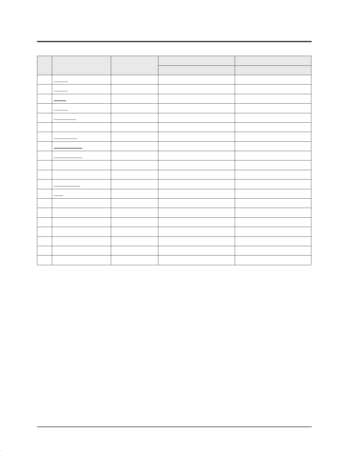
3-3 Factory Data
★ The underlined are items applied during the service adjustment. None of the others should be adjusted.
1. Deflection(NT 60Hz)
No Item Remark
29" SLIM 29" SLIM
CL-29Z30PQ CL-29Z30MQ
1 V Amp ADJ 42 42
2 V Shift ADJ -24 -24
3 H EW ADJ -6 -6
4 H Shift ADJ 130 130
5 V Linearity ADJ -3 -3
6 V SC FIX 43 43
7 H Parabola ADJ 78 78
8 Upper Corner ADJ 11 11
9 Lower Corner ADJ -29 -29
10 Upper Corner6 FIX -18 -18
11 Lower Corner6 FIX 3 3
12 H Trapezium ADJ 29 29
13 Bow ADJ 2 2
14 Angle FIX -1 -1
15 EHT Time FIX 20 20
16 EHT Threshold FIX 1 1
17 EHT Vertical FIX 0 0
18 EHT Horizontal FIX 24 24
19 EHT Vertical2 FIX 4 4
20 EHT Horizontal2 FIX 7 7
Alignment & Adjustment
3-4 Samsung Electronics
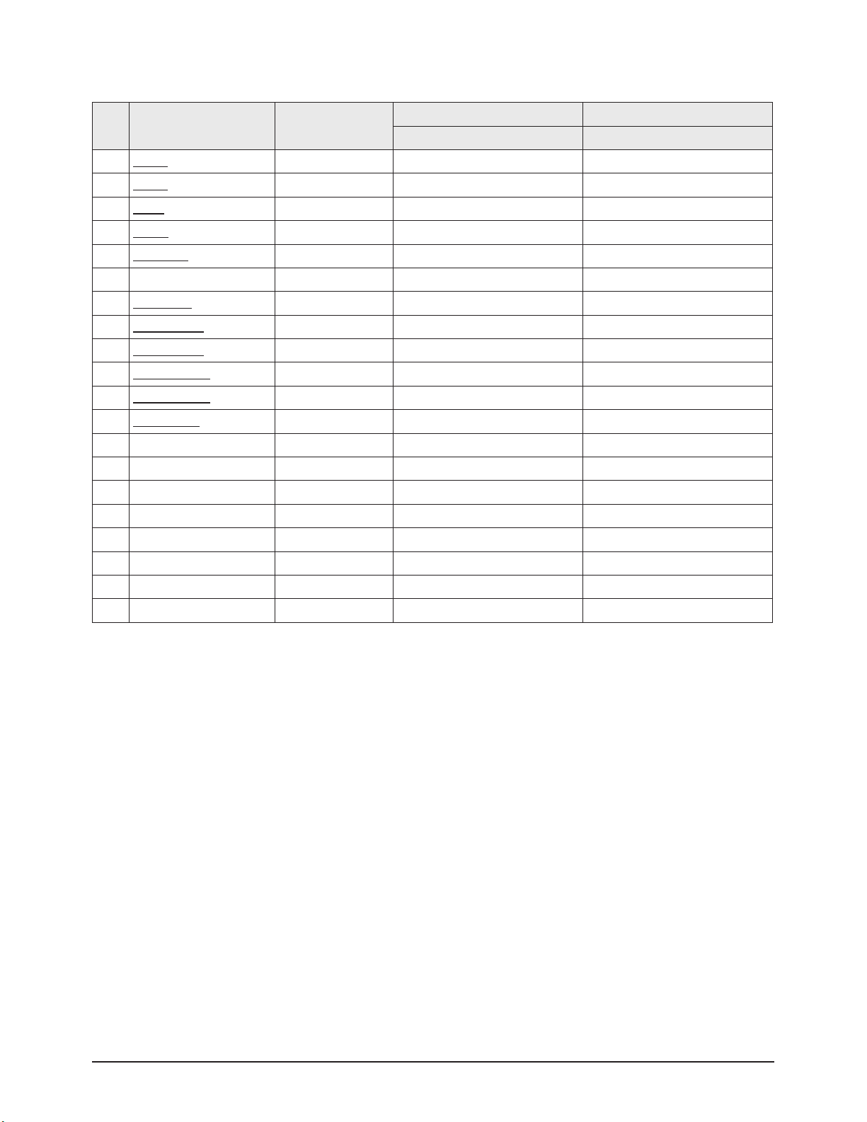
2. Deflection(PAL 50Hz)
No Item Remark
29" SLIM 29" SLIM
CL-29Z30PQ CL-29Z30MQ
1 V Amp ADJ 4 4
2 V Shift ADJ -5 -5
3 H EW ADJ 2 2
4 H Shift ADJ -17 -17
5 V Linearity ADJ 0 0
6 V SC FIX 0 0
7 H Parabola ADJ 2 2
8 Upper Corner ADJ -7 -7
9 Lower Corner ADJ -5 -5
10 Upper Corner6 ADJ 4 4
11 Lower Corner6 ADJ 6 6
12 H
Trapezium
ADJ -8 -8
13 Bow FIX 2 2
14 Angle FIX 0 0
15 EHT Time FIX 20 20
16 EHT Threshold FIX 1 1
17 EHT Vertical FIX 0 0
18 EHT Horizontal FIX 24 24
19 EHT Vertical2 FIX 4 4
20 EHT Horizontal2 FIX 7 7

Alignment & Adjustment
Samsung Electronics 3-5
0 V-AMP
1 V-Shift
2 H EW
H-Shift
3
6
H-Parabola
7 Upper Coner
8 Low Coner
9
H-Trapezium
4 V-Linearity
5
V SC
10 BOW
11 Angle

Alignment & Adjustment
3-6 Samsung Electronics
3. Video Adjust 1
No Item Remark
29" SLIM 29" SLIM
CL-29Z30PQ CL-29Z30MQ
1 R Cutoff ADJ 127 127
2 G Cutoff FIX 127 127
3 B Cutoff ADJ 127 127
4 R Drive ADJ 127 127
5 G Drive FIX 127 127
6 B Drive ADJ 127 127
7 Sub Bright ADJ 52 52
8 Sub Contrast ADJ 32 32
9 Sub Color FIX 2 2
10 Sub Tint FIX 46 46
11 AKB Option FIX 1 1
12 BCL Threshold FIX 19 19
13 BCL Gain FIX 240 240
14 BCL Time FIX 255 255
15 Sub Sharpness FIX 12 12
16 Pilot Low FIX 7 7
17 Pilot High FIX 13 13
18 V-Mute(x100ms) FIX 3 3
19 BCL TCUP FIX 100 100

Alignment & Adjustment
Samsung Electronics 3-7
4. Video Adjust 2
No Item Remark
29" SLIM 29" SLIM
CL-29Z30PQ CL-29Z30MQ
1 VSU FIX 2 2
2 Melody Volume FIX 5 5
3 HB Start FIX 159 159
4 HB Stop FIX 149 149
5 RF AGC FIX 4 4
6 VM Gain FIX 0 0
7 VM Delay FIX 0 0
8 V Peaking FIX 12 12
9 BLE Tilt FIX 12 12
10 BLE Gain FIX 1 1
11 BLE Mode FIX 2 2
12 BLE Break FIX 1 1
13 CTI Gain FIX 1 1
14 CTI Coring FIX 15 15
15 LTI Gain FIX 15 15
16 D-EHT Time FIX 5 5
17 DCT Ratio FIX 50 50
18 VSP COMB FIX 3 3

Alignment & Adjustment
3-8 Samsung Electronics
6. YC Delay
No Item Remark
29" SLIM 29" SLIM
CL-29Z30PQ CL-29Z30MQ
1 PAL Delay FIX 0 0
2 SECAM Delay FIX -2 -2
3 NTSC Delay FIX 0 0
4 PAL(AV) Delay FIX 0 0
5 SECAM(AV) Delay FIX -3 -3
6 NTSC(AV) Delay FIX 0 0
5. Video Adjust 3
No Item Remark
29" SLIM 29" SLIM
CL-29Z30PQ CL-29Z30MQ
1 NR Off Value FIX 3 3
2 Gamma Mode FIX 1 1
3 Gamma Correction FIX 70 70
4 BST StartPoint FIX 145 145
5 BST Gain(B) FIX 50 50
6 DPWL Gain FIX 80 80
7 DPWL Start FIX 185 185
8 PIP Contrast FIX 8 8
9 PIP Tint FIX 57 57
10 PIP Color FIX 6 6
11 PIP PAL V.Pos FIX 24 24
12 PIP NTSC V.Pos FIX 24 24
13 PIP H.Pos FIX 46 46
14 PIP R Cutoff FIX 6 6
15 PIP B Cutoff FIX 9 9
16 PIP R Drive FIX 161 161
17 PIP B Drive FIX 141 141

7. Test Pattern
No Item Remark
29" SLIM 29" SLIM
CL-29Z30PQ CL-29Z30MQ
1 G2 Adjust - - -
2 Read Cut - - -
3 Read Drive - - -
4 IBRM FIX 180 180
5 WDRM FIX 50 50
6 CDL FIX 254 254
7 COLR G B FIX 50 / 50 / 50 50 / 50 / 50
Alignment & Adjustment
Samsung Electronics 3-9

Alignment & Adjustment
3-10 Samsung Electronics
8. EEPROM
No Item Remark MIN MAX
29" SLIM 29" SLIM
CL-29Z30PQ CL-29Z30MQ
0 Dynamic Contrast FIX 0 255 100 100
1 Dynamic Brightness FIX 0 255 45 45
2 Dynamic Sharpness FIX 0 255 65 65
3 Dynamic Color FIX 0 255 43 43
4 Dynamic Tint FIX 0 255 50 50
5 Standard Contrast FIX 0 255 82 82
6 Standard Brightness FIX 0 255 45 45
7 Standard Sharpness FIX 0 255 50 50
8 Standard Color FIX 0 255 45 45
9 Standard Tint FIX 0 255 50 50
10 Movie Contrast FIX 0 255 50 50
11 Movie Brightness FIX 0 255 55 55
12 Movie Sharpness FIX 0 255 25 25
13 Movie Color FIX 0 255 40 40
14 Movie Tint FIX 0 255 50 50
15 255 255
16 255 255
17 255 255
18 255 255
19 DVD SUB TINT FIX 0 10 10
20 16:9 V-SHIFT FIX 0 100 15 15
21 16:9 PARAVOLA FIX 0 100 5 5
22 PIP BRIGHTNESS FIX 0 15 0 0
23 Double TTX Contrast FIX 255 255
24 TTX V Position FIX 0 255 255 255
25 TTX H Position FIX 0 255 255 255
26 TTX Contrast FIX 0 255 255 255
27 TTX Brightness FIX 0 255 255 255
28 OSD Contrast FIX 0 255 115 115
29 OSD Brightness FIX 0 255 15 15
30 Double TTX H Position FIX 0 255 255 255
31 Standard Equ100(Std BASS) FIX 0 8 50 50
32 Standard Equ300(Std TREBLE) FIX 0 13 50 50
33 Standard Equ1K(Music BASS) FIX 0 14 85 85
34 Standard Equ3K(Music TREBLE) FIX 0 13 70 70
35 Standard 10K(Movie BASS) FIX 0 12 95 95
36 Music Equ100(Movie TREBLE) FIX 0 18 50 50
37 Music Equ300(Speech BASS) FIX 0 14 40 40

Alignment & Adjustment
Samsung Electronics 3-11
No Item Remark MIN MAX
29" SLIM 29" SLIM
CL-29Z30PQ CL-29Z30MQ
38 Music Equ1K(Speech TREBLE) FIX 0 11 50 50
39 Music Equ3K FIX 0 14 255 255
40 Music 10K FIX 0 18 255 255
41 Movie Equ100 FIX 0 22 255 255
42 Movie Equ300 FIX 0 15 255 255
43 Movie Equ1K FIX 0 11 255 255
44 Movie Equ3K FIX 0 12 255 255
45 Movie 10K FIX 0 13 255 255
46 Speech Equ100 FIX 0 6 255 255
47 Speech Equ300 FIX 0 11 255 255
48 Speech Equ1K FIX 0 14 255 255
49 Speech Equ3K FIX 0 13 255 255
50 Speech 10K FIX 0 11 255 255
51 Brightness(RGB/DVD) FIX 0 255 6 6
52 Contrast(RGB/DVD) FIX 0 63 42 42
53 U Saturation(RGB/DVD) FIX 0 63 44 44
54 V saturation(RGB/DVD) FIX 0 63 43 43
55 V/FBL Delay FIX 0 255 85 85
56 CrCb Delay FIX 0 255 84 84
57 d/w h-position FIX 0 255 255 255
58 d/w -blanking 1 FIX 0 255 255 255
59 d/w -blanking 2 FIX 0 255 255 255
60 PIP G CUTOFF FIX 0 255 4 4
61 PIP G DRIVE FIX 0 255 170 170
62 OSD/PIP BRIGHT BALANCE FIX 0 31 31 31
63 PIP BRIGHT OFFSET FIX 0 255 86 86
64 MDB_STRENGTH FIX 0 127 68 68
65 MDB_HARMONIC FIX 0 127 37 37
66 MDB_HP FIX 0 30 9 9
67 MDB_LP FIX 0 30 11 11
68 MDB_LIM FIX 0 255 252 252
69 MDB_CUTOFF FIX 0 40 12 12
70 EHT POSITION 1 FIX 0 255 5 5
71 EHT POSITION 2 FIX 0 255 249 249
72 3.4CH SLLTHD (TV-NO NOISE) FIX 0 3 0 0
73 CH SLLTHD (TV-NO NOISE) FIX 0 3 0 0
74 LNA Operating Point FIX 0 255 166 166
75 SLLTHDV(TV NO NOISE) FIX 0 6 0 0

Alignment & Adjustment
3-12 Samsung Electronics
No Item Remark MIN MAX
29" SLIM 29" SLIM
CL-29Z30PQ CL-29Z30MQ
76 LNA Default FIX 0 1 0 0
77 LNA SWITCH FIX 0 1 0 0
78 LMIXOFS FIX 0 13 13 13
79 H-OUTDEL FIX 0 255 72 72
80 CR-P Initial FIX 0 255 4 4
81 CR-I Initial FIX 0 255 5 5
82 DRX_CR_AMP_TH FIX 0 255 10 10
83 Over Modulation Return Counter FIX 0 255 100 100
84 VCR Mode Counter FIX 0 255 5 5
85
"VID_AMP_HEAD_BS(In the modulation)"
FIX 0 255 40 40
86 CR_P (In the Over Modulation) FIX 0 255 4 4
87
"THRSEL(picture shaking when weak
signal)"
FIX 0 255 2 2
88 SLLTHDVP FIX 0 255 1 1
89 EEP_BC_MIN_LIMIT FIX 0 255 150 150
 Loading...