

Samsung CL21Z50MQ3XXAP Service Manual
COLOR TELEVISION
Chassis : K16C(N)_Valiant
Model : CL21Z50MQ3XXAP
SERVICE
Manual
COLOR TELEVISION CONTENTS
1. Precaution
2. Product Specification
3.
Disassembly & Reassembly
4. Troubleshooting
5.
Exploded View & Part List
6. Wiring Diagram
7.
Schematic Diagram
CL-21Z50MQ
Refer to the service manual in the GSPN (see the rear cover) for the more information.


Table of Contents
1. Precaution
1-1 Safety Precautions ......................................................................................................................................................1-1
1-2 Servicing Precautions ..................................................................................................................................................1-3
1-3
Static Electricity Precautions .......................................................................................................................................1-4
1-4
Installation Precautions ...............................................................................................................................................1-5
2. Product Specification
2-1 Product Specification ...................................................................................................................................................2-1
2-2 Specifications Analysis ................................................................................................................................................2-2
2-4
Accessories .................................................................................................................................................................2-3
3. Disassembly & Reassembly
3-1 Overall Disassembly & Reassembly ............................................................................................................................3-1
4. Troubleshooting
4-1 Troubleshooting ...........................................................................................................................................................4-1
4-2 Adjustment ...................................................................................................................................................................4-14
5. Exploded View & Part List
5-1 CL21Z50MQ3XXAP Exploded View ............................................................................................................................5-1
5-2 CL21Z50MQ3XXAP Service Item .................................................................................................................
...............5-3
6. Wiring Diagram
6-1 Overall Wiring ..............................................................................................................................................................6-1
7. Schematic Diagram
7-1 Circuit Description .......................................................................................................................................................7-1
7-2 Schematic Diagram .....................................................................................................................................................7-5
2. Product Specification
2-1 Product Specification
Features
Block Specification Major IC Remark
CRT 21” FLAT Slim CRT 21” Vixlim CRT
RF Part 1 TUNER F/S TUNER TDQ-6F/13F2S
Product Specification
Power
Video
Sound
Cabinet 21Z50 Cabinet Z50 Cabinet
Model CL-21Z50MQ
Screen Size 21”
Dimensions (WxHxD) 690 x 435 x 580 mm
Weight 19.5 kg
Voltage Mexico:AC 110V(Other: AC100 ~ 240V)
Speaker Output 5W + 5W
Input Voltage : Mexico:AC 110V(Other: AC100 ~ 240V)
Stand-By : 3W UNDER
NTSC 3.58, ATSC
1H Comb Filter
Interlaced Scan
Output : 5W x 2 VCT4822, LA42032
Function : MTS, Surround, Turbo
Specification
STR-W6750F
VCT4822
Samsung Electronics 2-1
Product Specification
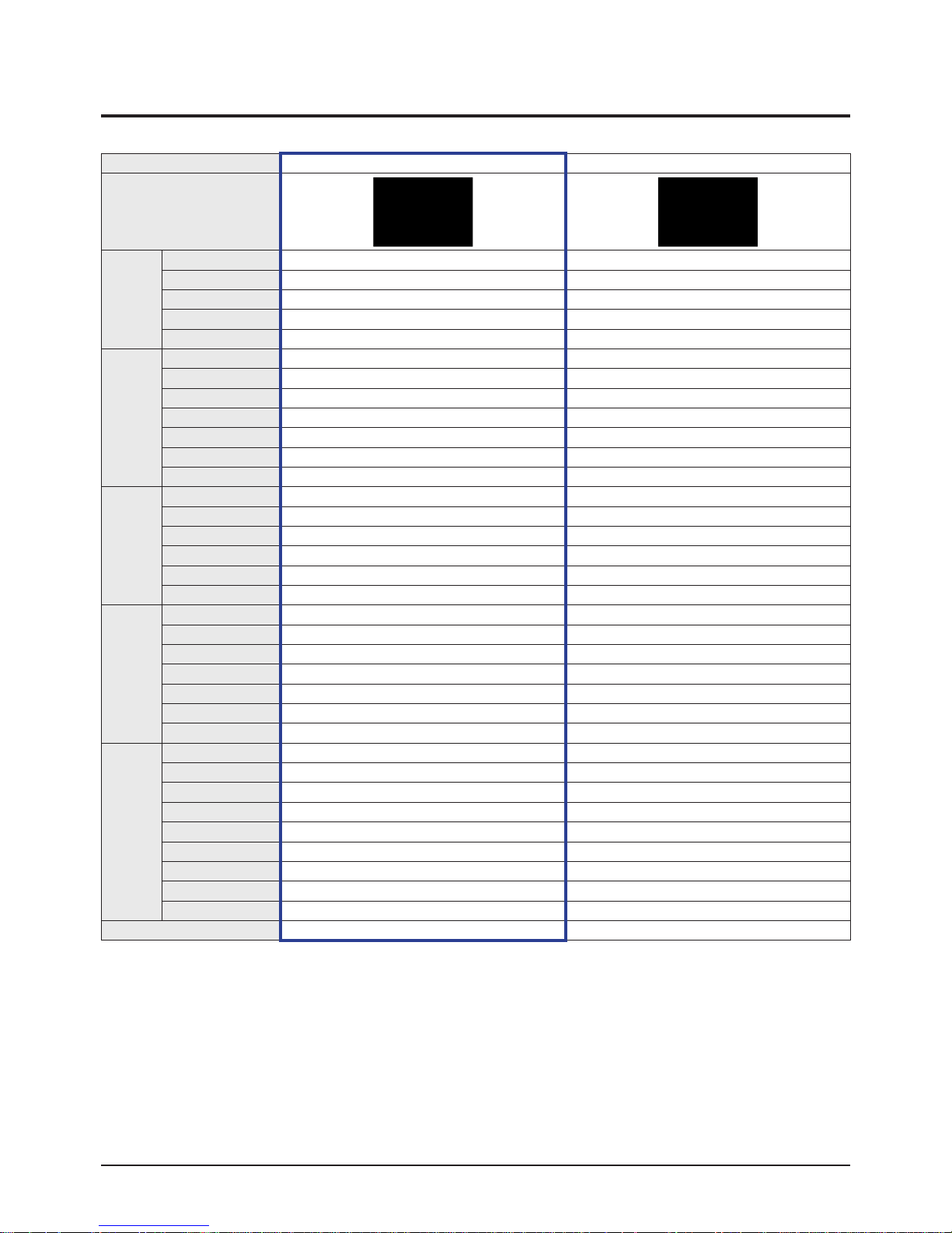
2-2 Specifications Analysis
Model CL-21Z50MQ CL-21Z50MQ
Design
Product Type FLAT CRT FLAT CRT
Digital TV Analog Analog
Basic
Visual
Quality
Audio
Function
Ports
※
For the power supply and power consumption, refer to the label attached to the product.
Digital Display 480i 480i
Screen Size 21 21
Aspect Ratio 4:3 4:3
Progressive Scan
Digital Comb Filter
Screen Pitch 0.73 0.73
Digital Noise Reduction
AKB
DNle
3:2 Pull Down Support
Base/Treble/Balance
Equalizer
AVL
Surround
Speaker System Direct Direct
Sperker Output 5W + 5W 10W + 10W
Dual Screen Function
Double Screen
Caption Eng Eng
Still Picture
Auto Jack Recognition
EPG
Network
Antenna In Rear:1 Rear:2
Extermal In Rear1, side1 Rear1, side1
S-Video
Y/Pb/Pr Rear:1 Rear:1
PC
DVI
HDMI
Digital Audio Out
Video Out Rear:1 Rear:1
Remote Controller TM85 TM85
※
: application, : non-application
2-2 Samsung Electronics
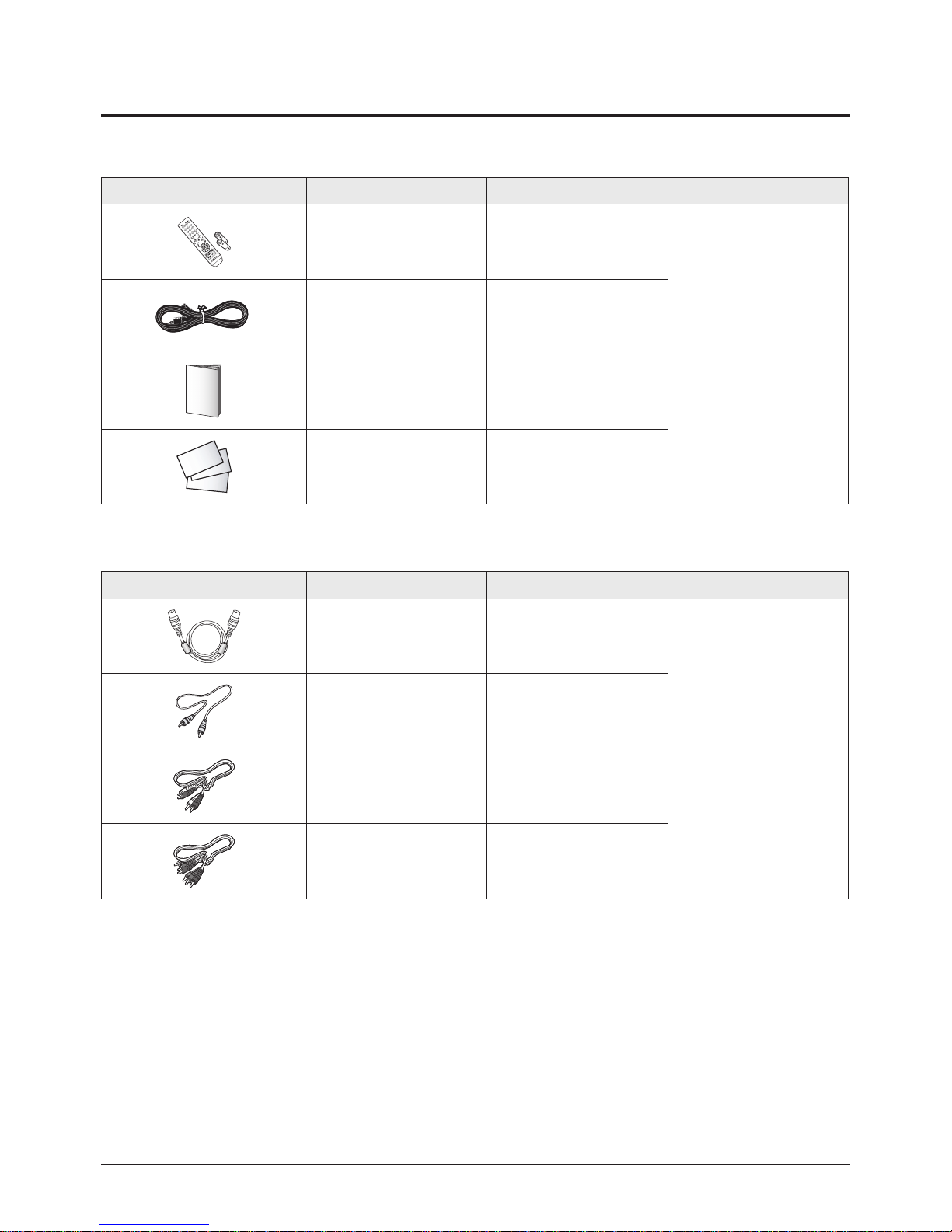
2-3 Accessories
2-3-1 Supplied Accessories
Accessories Item Item code Remark
Product Specification
Remote Control
Batteries
Power Cord -
Owner’s Instructions AA68-03806H
Warranty Card
Registration Card
Safety Guide Manual
2-3-2 Accessories that can be purchased additionally
Accessories Item Item code Remark
RF Cable -
AA59-00385C
4301-000103
Samsung Service center
AA68-03727A
-
AA68-03242L
Video Cable -
Audio Cable -
Component Cables (RCA) -
Electronics Store/
Internal shopping mall
Samsung Electronics 2-3

MEMO
2-4 Samsung Electronics
1. Make sure all protective devices are properly installed
including non-metallic handles and compartment covers
when installing or re-installing the chassis or chassis
assemblies.
2. Make sure that no gaps exist between the cabinets for
children to insert their fingers in to prevent children from
receiving electric shocks. Gaps mentioned above include
ventilation holes of a too great magnitude between the
vaccum tube and the cabinet mask, and the improper
installation of the rear cabinet.
Errors may occur when the resistance is below 1.0 ㏁ or
over 5.2 ㏁.
In these cases, make sure that the device is repaired
before sending it back to the customer.
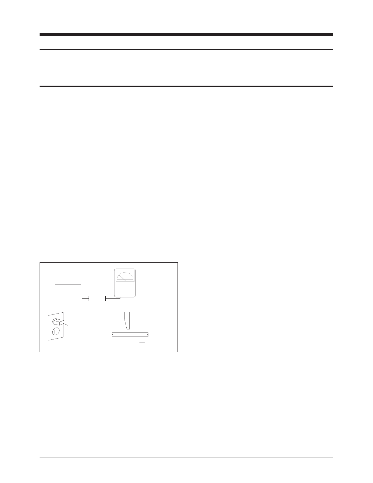
3. Check for Electricity Leakage (Figure 1-1)
Warning: Do not use an insulated transformer for checking the leakage. Use only those current leakage testers
or mirroring systems that comply with ANSIC 101.1 and
the Underwriter Laboratory's specifications (UL1410,
59.7).
Fig. 1-1 AC Leakage Test
4. Ahigh voltage is maintained within the specified limits
using safety parts, calibration and tolerances. When
voltage exceeds the specified limits, check each special
part.
5. Warning for Engineering Changes:
Never make any changes or additions to the circuit
design or the internal part for this product.
Ex: Do not add any audio or video accessory
connectors. This might cause physical damage.
Furthermore, any changes or additions to the original
design/engineering will invalidate the warranty.
6. Warning - Hot Chassis:
Some TV chassis are directly connected to one end of
the AC power cord for electrical reasons.
Without insulated transformers, the product can only be
repaired safely when the chassis is connected to the
earthed end of the AC power source.
To make sure the AC power cord is properly connected,
follow the instructions below. Use the voltmeter to
measure the voltage between the chassis and the
earthed ground. If the measurement is over 1.0V, unplug
the AC power cord and change the polarity before reinserting it. Measure the voltage between the chassis
and the ground again.
7. Some TV chassis are shipped with an additional
secondary grounding system. The secondary system is
adjacent to the AC power line. These two grounding
systems are separated in the circuit using an
unbreakable/unchangeable insulation material.
8. When any parts, material or wiring appear overheated or
damaged, replace them with new regular ones
immediately. When any damage or overheating is
detected, correct this immediately and make a regular
check of possible errors.
9. Check for the original shape of the lead, especially that
of the antenna wiring, any sharp edges, the AC power
and the high voltage power. Carefully check if the wiring
is too tight, incorrectly placed or loose. Never change the
space between the part and the printed circuit board.
Check the AC power cord for possible damages. Keep
the part or the lead away from any heat-emitting
materials.
Precaution
Samsung Electronics 1-1
To avoid possible damages or electric shocks or exposure to radiation, follow the instructions below with regard to safety,
installation, service and ESD.
1. Precaution
1-1 Safety Precautions
(READING SHOULD
DEVICE
UNDER
TEST
2-WIRE CORD
ALSO TEST WITH
PLUG REVERSED
(USING AC ADAPTER
PLUG AS REQUIRED)
TEST ALL
EXPOSED METAL
SURFACES
LEAKAGE
CURRENT
TESTER
NOT BE ABOVE
0.5mA)
EARTH
GROUND

10. Safety Indication:
Some electrical circuits or device related materials
require special attention to their safety features, which
cannot be viewed by the naked eye. If an original part is
replaced with another irregular one, the safety or
protective features will be lost even if the new one has a
higher voltage or more watts.
Critical safety parts should be bracketed with ( ).
Use only regular parts for replacements (in particular,
flame resistance and dielectric strength specifications).
Irregular parts or materials may cause electric shock or
fire.
Precaution
1-2 Samsung Electronics
!

1. The service instructions are printed on the cabinet, and
should be followed by any service personnel.
2. Make sure to unplug the AC power cord from the power
source before starting any repairs.
(a) Remove or re-install parts or assemblies.
(b) Disconnect the electric plug or connector, if any.
(c) Connect the test part in parallel with the electrolytic
capacitor.
3. Some parts are placed at a higher position than the
printed board. Insulated tubes or tapes are used for this
purpose. The internal wiring is clamped using buckles to
avoid contact with heat emitting parts. These parts are
installed back to their original position.
4. After the repair, make sure to check if the screws, parts
or cables are properly installed. Make sure no damage is
caused to the repaired part and its surroundings.
5. Check for insulation between the blade of the AC plug
and that of any conductive materials (i.e. the metal
panel, input terminal, earphone jack, etc).
6. Insulation Check Process: Unplug the power cord from
the AC source and turn the switch on. Connect the insulating resistance meter (500v) to the AC plug blade.
The insulating resistance between the blade of the AC
plug and that of the conductive material should be more
than 1 ㏁.
7. Any B+ interlock should not be damaged.
If the metal heat sink is not properly installed, no
connection to the AC power should be made.
8. Make sure the grounding lead of the tester is connected
to the chassis ground before connecting to the positive
lead. The ground lead of the tester should be removed
last.
9. Beware of risks of any current leakage coming into
contact with the high-capacity capacitor.
10. The sharp edges of the metal material may cause
physical damage, so ensure wearing protective gloves
during the repair.
Precaution
Samsung Electronics 1-3
Warning 1: First carefully read the "Safety Instruction" in this service manual.
When there is a conflict between the service and the safety instructions, follow the safety instruction at all times.
Warning 2: Any electrolytic capacitor with the wrong polarity will explode.
1-2 Servicing Precautions

1-3 Static Electricity Precautions
1. Some semi-conductive ("solid state") devices are
vulnerable to static electricity. These devices are known
as ESD. ESD includes the integrated circuit and the field
effect transistor. To avoid any materials damage from
electrostatic shock, follow the instructions described
below.
2. Remove any static electricity from your body by
connecting the earth ground before handling any
semi-conductive parts or ass'ys. Alternatively, wear a
dischargeable wrist-belt.
(Make sure to remove any static electricity before
connecting the power source - this is a safety instruction
for avoiding electric shock)
3. Remove the ESD ass'y and place it on a conductive
surface such as aluminum foil to prevent accumulating
static electricity.
4. Do not use any Freon-based chemicals.
Such chemicals will generate static electricity that
causes damage to the ESD.
5. Use only grounded-tip irons for soldering purposes.
6. Use only anti-static solder removal devices.
Most solder removal devices do not support an
anti-static feature. Asolder removal device without an
anti-static feature can store enough static electricity to
cause damage to the ESD.
7. Do not remove the ESD from the protective box until the
replacement is ready. Most ESD replacements are
covered with lead, which will cause a short to the entire
unit due to the conductive foam, aluminum foil or other
conductive materials.
8. Remove the protective material from the ESD
replacement lead immediately after connecting it to the
chassis or circuit ass'y.
9. Take extreme caution in handling any uncovered ESD
replacements. Actions such as brushing clothes or lifting
your leg from the carpet floor can generate enough static
electricity to damage the ESD.
Precaution
1-4 Samsung Electronics
CAUTION
These servicing instructions are for use by
qualified service personnel only.
To reduce the risk of electric shock do not
perform any servicing other than that contained in the
operating instructions unless you are qualified to do so.

Precaution
Samsung Electronics 1-5
1-4 Installation Precautions
1. For safety reasons, more than two people are required
for carrying the product.
2. Keep the power cord away from any heat emitting
devices, as a melted covering may cause fire or electric
shock.
3. Do not place the product in areas with poor ventilation
such as a bookshelf or closet. The increased internal
temperature may cause fire.
4. Bend the external antenna cable when connecting it to
the product. This is a measure to protect it from being
exposed to moisture. Otherwise, it may cause a fire or
electric shock.
5. Make sure to turn the power off and unplug the power
cord from the outlet before repositioning the product.
Also check the antenna cable or the external connectors
if they are fully unplugged. Damage to the cord may
cause fire or electric shock.
6. Keep the antenna far away from any high-voltage cables
and install it firmly. Contact with the high-voltage cable or
the antenna falling over may cause fire or electric shock.
7. Check the basics of the screen test.
- Image position/size, Tilt adjustment

1-6 Samsung Electronics
MEMO
 Loading...