

Specifications
Alignment and Adjustments
Exploded View & Part List
Electrical Part List
PCB Diagram
Schematic Diagrams
1.
2.
3.
4.
5.
6.
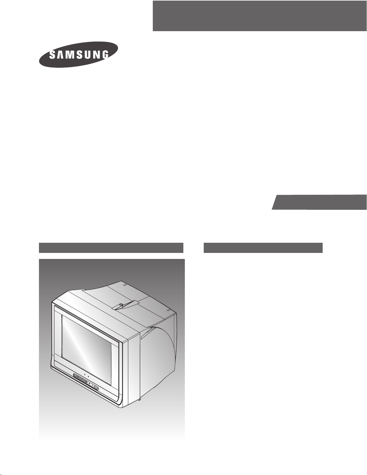
COLOR TELEVISION RECEIVER
Chassis : KS9A(N)
Model : CL21M16MNZXBDB
SERVICE
Manual
COLOR TELEVISION RECEIVER CONTENTS
This Service Manual is a property of Samsung Electronics Co.,Ltd.
Any unauthorized use of Manual can be punished under applicable
International and/or domestic law.
© Samsung Electronics Co., Ltd. Nov. 2005
Printed in Korea
AA82-03146A
ELECTRONICS
Specifications
Samsung Electronics 1-1
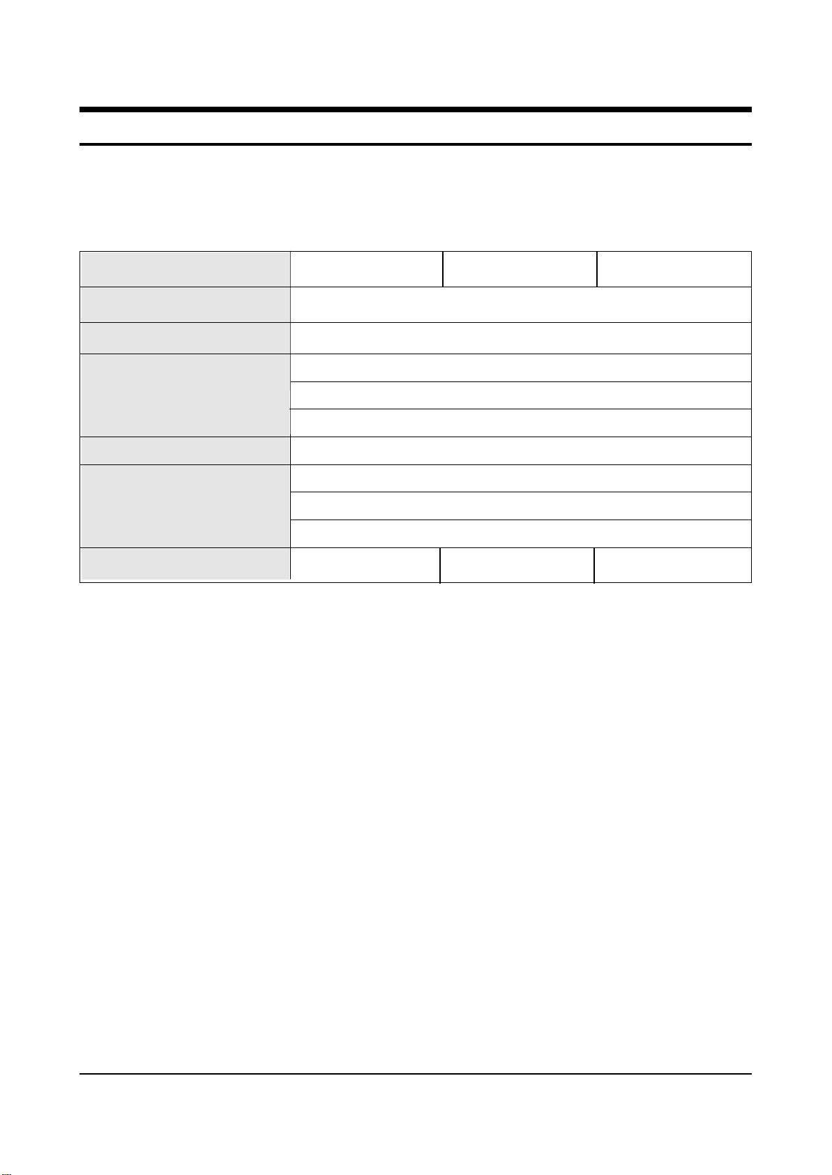
1. Specifications
Broadcasting System
Regions
Tuning System
Intermediate Frequency
Power Supply
NTSC
North America
Electronic Remote Control System
VHF (CH 2 ~ 13)
UHF (CH 14 ~ 69)
CATV (CH 1, 14 ~ 125)
VHF, UHF 75 unbalanced
Video : 45.75 MHz
Sound : 41.25 MHz
Chrominance Subcarrier: 42.17 MHz
ANTENNA INPUT RESISTANCE
Receiving Channels
South Central America MEXICO
AC 120V, 60Hz AC 100~240V, 60Hz AC 120V, 60Hz

MEMO
1-2 Samsung Electronics
Alignment and Adjustments
Samsung Electronics 2-1
2. Alignment and Adjustments
2-1 General Alignment Instructions
1. Usually, a color TV-VCR needs only slight
touch-up adjustment upon installation. Check
the basic characteristics such as height,
horizontal and vertical sync and focus.
2. Observe the picture for good black and white
details. There should be objectionable color
shading; if color shading is present,
demagnetize, perform purity and convergence
adjustments described below.
3. Use the specified test equipment or its
equivalent.
4. Correct impedance matching is essential.
5. Avoid overload. Excessive signal from a
sweep generator might overload the front-end
of the TV. When inserting signal markers, do
not allow the marker generator to distort test
results.
6. Connect the TV only to an AC power source
with voltage and frequency as specified on the
backcover nameplate.
7. Do not attempt to connect or disconnect any
wires while the TV is turned on. Make sure
that the power cord is disconnected before
replacing any parts.
8. To protect against shock hazard, use an
isolation transformer.
2-2 Automatic Degaussing
A degaussing coil is mounted around the
picture tube, so that external degaussing after
moving the TV should be unnecessary. But
the receiver must be properly degaussed upon
installation.
The degaussing coil operates for about 1
second after the power is switched ON. If the
set is moved or turned in a different direction,
the power should be OFF for at least 10
minutes.
If the chassis or parts of the cabinet become
magnetized, poor color purity will result. If
this happens, use an external degaussing coil.
Slowly move the degaussing coil around the
faceplate of the picture tube and the sides and
front of the receiver. Slowly withdraw the coil
to a distance of about 6 feet before turning
power OFF.
If color shading persists, perform the
following Color purity and Convergence
adjustments.
2-3 High Voltage Check
CAUTION : There is no high voltage adjustment
on this chassis. The B+ power supply should be
+135 volts (with full color- bar input and normal
picture level).
1. Connect a digital voltmeter to the second
anode of the picture tube.
2. Turn on the TV. Set the Brightness and
Contrast controls to minimum (zero beam
current).
3. Adjust the Brightness and contrast controls to
both extremes. Ensure that the high voltage
does not exceed 30 KV under any conditions.
Alignment and Adjustments
2-2 Samsung Electronics
2-4 FOCUS Adjustment
1. Iput a black and white signal.
2. Adjust the tuning control for the clearest picture.
3. Adjust the FOCUS control for well defined scanning lines in the center area of the screen.
2-5 Factory Adjustment
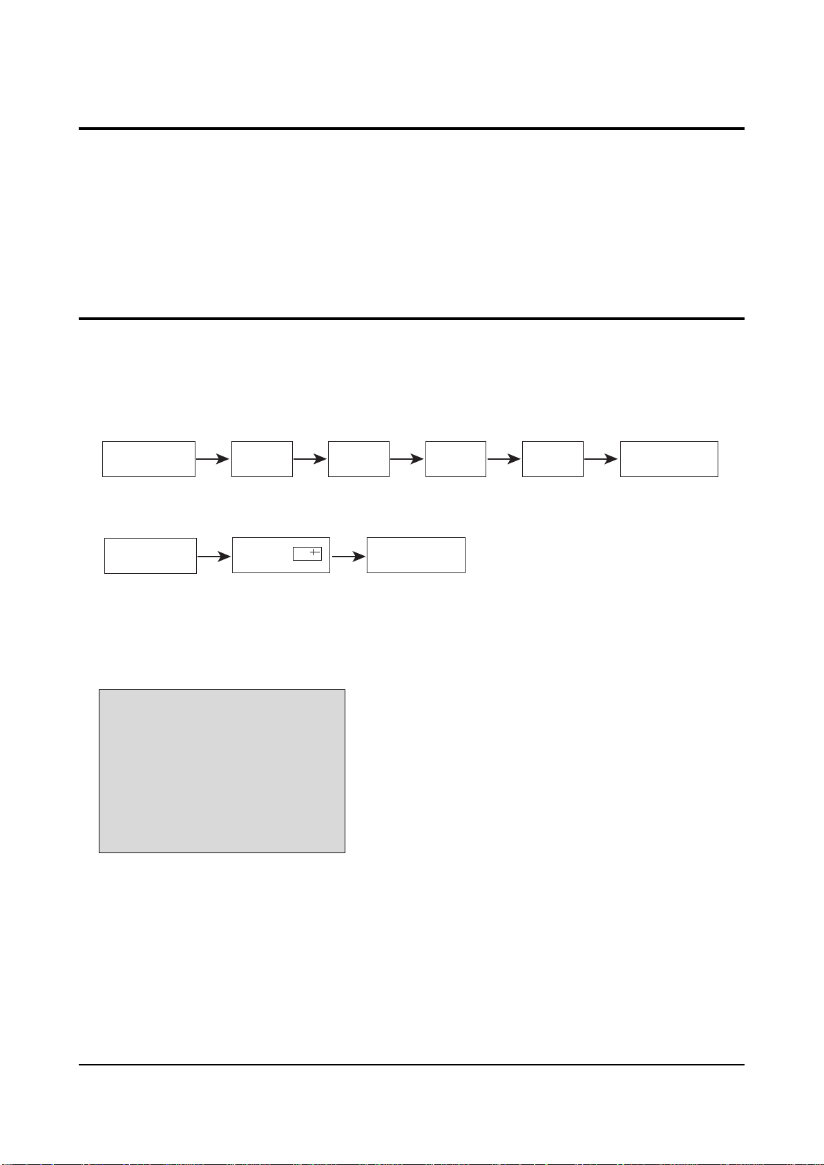
1. To enter the “Service Mode”, Press the remote-control keys in this sequence :
- If you do not have Factory remote-control
- If you have Factory remote-control
2-5-1 Service Mode
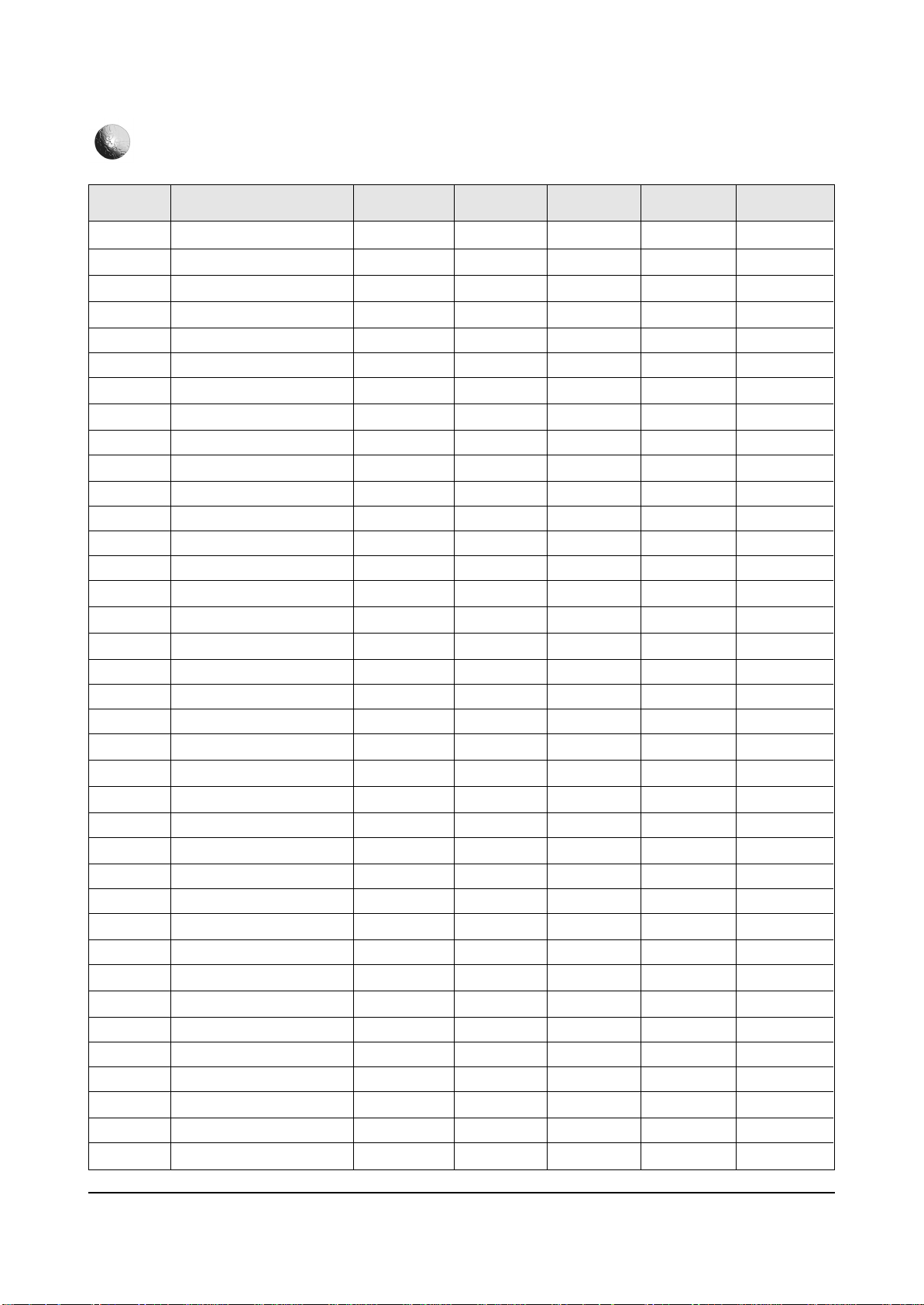
2-5-2 Factoy Mode OSD
ADJUST
OPTION
CHCKSUM
RESET
T-FMTNUS-0000
2-5-2 ADJUST
PICTURE OFF PICTURE ON
MUTE 1 8 2
PICTURE ON
DISPLAY
)
(
FACTORY
Alignment and Adjustments
Samsung Electronics 2-3
No Deflection
Remark
1
2
3
4
5
6
7
8
9
10
11
12
13
14
15
16
17
18
19
20
21
22
23
24
25
26
27
28
29
30
31
32
33
34
35
36
37
Adjust
Adjust
Adjust
FIX
Adjust
FIX
Adjust
Adjust
Adjust
Adjust
Adjust
FIX
Adjust
FIX
FIX
FIX
FIX
FIX
FIX
FIX
FIX
FIX
FIX
FIX
FIX
FIX
FIX
FIX
FIX
FIX
FIX
FIX
FIX
FIX
FIX
FIX
FIX
INITIAL
37
34
30
31
33
9
10
7
28
43
30
32
46
29
5
0
1
5
10
7
1
1
12
0
1
15
3
13
1
40
5
17
0
6
32
32
0
MIN
0
0
0
0
0
0
0
0
0
0
0
0
0
0
0
0
0
0
0
0
0
0
0
0
0
0
0
0
0
0
0
0
0
0
0
0
0
MAX
63
63
63
63
63
15
23
23
63
63
63
63
63
63
7
1
15
23
63
50
1
1
15
1
3
63
3
15
1
63
20
23
23
16
63
63
1
ADJUST
30
22
23
25
33
9
10
7
28
43
30
32
46
33
5
0
1
10
10
7
1
1
12
0
1
15
3
15
1
40
5
10
0
9
32
32
0
HS
VA
VSL
VS
AGC
CDL
SCT
SBT
BLR
BLB
RG
GG
BG
SC
STT
AKB
NDL
NSR
VOL
MVOL
RPO0
RPO1
CAP
FMWS
AGCS
OMD
SCL
PWL
MUS
SCBT
SSP
DNSR
DSBT
DCDL
DBLR
DBLB
DSK
T-FMTNUS FACTORY
 Loading...