

Samsung CL21K40MQGXXAZ Schematic

COLOR TELEVISION RECEIVER
Chassis : KS9C(N)RAY
Model : CL21K40MQGXXAZ
COLOR TELEVISION RECEIVER FEATURES
■■
Turbo Sound
■
Sound Equalizer
■■
New Structure Design
SERVICE
Manual
CL-21K40MQ

Table of Contents
Chapter 1 Precaution
■ 1-1 Safety Precautions . . . . . . . . . . . . . . . . . . . . . . . . . . . . . . . . . . . . . . . . . . . . . . . . . . . . . . . . . . . 1-1
■ 1-2 Servicing Precautions . . . . . . . . . . . . . . . . . . . . . . . . . . . . . . . . . . . . . . . . . . . . . . . . . . . . . . . . 1-3
■ 1-3 Static Electricity Precautions . . . . . . . . . . . . . . . . . . . . . . . . . . . . . . . . . . . . . . . . . . . . . . . . . . . 1-4
■ 1-4 Installation Precautions . . . . . . . . . . . . . . . . . . . . . . . . . . . . . . . . . . . . . . . . . . . . . . . . . . . . . . . 1-5
Chapter 2 Product Specification
■ 2-1 Product Features . . . . . . . . . . . . . . . . . . . . . . . . . . . . . . . . . . . . . . . . . . . . . . . . . . . . . . . . . . . . 2-1
■ 2-2 Key Features . . . . . . . . . . . . . . . . . . . . . . . . . . . . . . . . . . . . . . . . . . . . . . . . . . . . . . . . . . . . . . . 2-2
■ 2-3 Specifications Analysis . . . . . . . . . . . . . . . . . . . . . . . . . . . . . . . . . . . . . . . . . . . . . . . . . . . . . . . . 2-3
■ 2-4 Accessories . . . . . . . . . . . . . . . . . . . . . . . . . . . . . . . . . . . . . . . . . . . . . . . . . . . . . . . . . . . . . . . . 2-4
Chapter 3 Alignment & Adjustment
■ 3-1 Service Instruction . . . . . . . . . . . . . . . . . . . . . . . . . . . . . . . . . . . . . . . . . . . . . . . . . . . . . . . . . . . 3-1
■ 3-2 How to Access Service Mode . . . . . . . . . . . . . . . . . . . . . . . . . . . . . . . . . . . . . . . . . . . . . . . . . . . 3-2
■ 3-3 Factory Data . . . . . . . . . . . . . . . . . . . . . . . . . . . . . . . . . . . . . . . . . . . . . . . . . . . . . . . . . . . . . . . . 3-3
■ 3-4 Service Adjustment . . . . . . . . . . . . . . . . . . . . . . . . . . . . . . . . . . . . . . . . . . . . . . . . . . . . . . . . . . 3-6
■ 3-5 Replacements & Calibration . . . . . . . . . . . . . . . . . . . . . . . . . . . . . . . . . . . . . . . . . . . . . . . . . . . . 3-8
Chapter 4 Exploded View & Part List
■ 4-1 CL21K40MQGXXAZ . . . . . . . . . . . . . . . . . . . . . . . . . . . . . . . . . . . . . . . . . . . . . . . . . . . . . . . . . 4-1
Chapter 5 Electrical Part List
■ 5-1 CL21K40MQGXXAZ . . . . . . . . . . . . . . . . . . . . . . . . . . . . . . . . . . . . . . . . . . . . . . . . . . . . . . . . . 5-1
Chapter 6 Troubleshooting
■ 6-1 Checkpoints by Error Mode . . . . . . . . . . . . . . . . . . . . . . . . . . . . . . . . . . . . . . . . . . . . . . . . . . . . 6-1
■ 6-2 Troubleshooting Procedures by Error Modes . . . . . . . . . . . . . . . . . . . . . . . . . . . . . . . . . . . . . . . 6-2
■ 6-3 Troubleshooting Procedures by ASS'Y . . . . . . . . . . . . . . . . . . . . . . . . . . . . . . . . . . . . . . . . . . . 6-3
■ 6-4 Troubleshooting by Blocks . . . . . . . . . . . . . . . . . . . . . . . . . . . . . . . . . . . . . . . . . . . . . . . . . . . . . 6-5
Chapter 7 Block Diagram
■ 7-1 Overall Block Diagram . . . . . . . . . . . . . . . . . . . . . . . . . . . . . . . . . . . . . . . . . . . . . . . . . . . . . . . . 7-1
■ 7-2 Partial Block Diagram . . . . . . . . . . . . . . . . . . . . . . . . . . . . . . . . . . . . . . . . . . . . . . . . . . . . . . . . . 7-2
Chapter 8 Wiring Diagram
■ 8-1 Overall Wiring . . . . . . . . . . . . . . . . . . . . . . . . . . . . . . . . . . . . . . . . . . . . . . . . . . . . . . . . . . . . . . . 8-1
■ 8-2 Pin Connection . . . . . . . . . . . . . . . . . . . . . . . . . . . . . . . . . . . . . . . . . . . . . . . . . . . . . . . . . . . . . . 8-2

Chapter 9 PCB Diagram
■ 9-1 Main Board . . . . . . . . . . . . . . . . . . . . . . . . . . . . . . . . . . . . . . . . . . . . . . . . . . . . . . . . . . . . . . . . . 9-1
■ 9-2 CRT Board . . . . . . . . . . . . . . . . . . . . . . . . . . . . . . . . . . . . . . . . . . . . . . . . . . . . . . . . . . . . . . . . . 9-3
Chapter 10 Schematic Diagram
■ 10-1 Power . . . . . . . . . . . . . . . . . . . . . . . . . . . . . . . . . . . . . . . . . . . . . . . . . . . . . . . . . . . . . . . . . . . . 10-1
■ 10-2 Micom . . . . . . . . . . . . . . . . . . . . . . . . . . . . . . . . . . . . . . . . . . . . . . . . . . . . . . . . . . . . . . . . . . . . 10-2
■ 10-3 Audio . . . . . . . . . . . . . . . . . . . . . . . . . . . . . . . . . . . . . . . . . . . . . . . . . . . . . . . . . . . . . . . . . . . . 10-3
■ 10-4 Side A/V & CRT Board . . . . . . . . . . . . . . . . . . . . . . . . . . . . . . . . . . . . . . . . . . . . . . . . . . . . . . . 10-4
Chapter 11 Operation Instruction & Installation
■ 11-1 Product Features and Functions . . . . . . . . . . . . . . . . . . . . . . . . . . . . . . . . . . . . . . . . . . . . . . . 11-1
Chapter 12 Disassembly & Reassembly
■ 12-1 Overall Disassembly & Reassembly . . . . . . . . . . . . . . . . . . . . . . . . . . . . . . . . . . . . . . . . . . . . 12-1
Chapter 13 Circuit Description
■ 13-1 Overall Block Description . . . . . . . . . . . . . . . . . . . . . . . . . . . . . . . . . . . . . . . . . . . . . . . . . . . . . 13-1
■ 13-2 Partial Block Description . . . . . . . . . . . . . . . . . . . . . . . . . . . . . . . . . . . . . . . . . . . . . . . . . . . . . 13-2
Chapter 14 Reference Information
■ 14-1 Option Byte . . . . . . . . . . . . . . . . . . . . . . . . . . . . . . . . . . . . . . . . . . . . . . . . . . . . . . . . . . . . . . . 14-1
■ 14-2 Technical Terms . . . . . . . . . . . . . . . . . . . . . . . . . . . . . . . . . . . . . . . . . . . . . . . . . . . . . . . . . . . . 14-2
1. Make sure all protective devices are properly installed
including non-metallic handles and compartment covers
when installing or re-installing the chassis or chassis
assemblies.
2. Make sure that no gaps exist between the cabinets for
children to insert their fingers in to prevent children from
receiving electric shocks. Gaps mentioned above include
ventilation holes of a too great magnitude between the
vaccum tube and the cabinet mask, and the improper
installation of the rear cabinet.
Errors may occur when the resistance is below 1.0 ㏁ or
over 5.2 ㏁.
In these cases, make sure that the device is repaired
before sending it back to the customer.
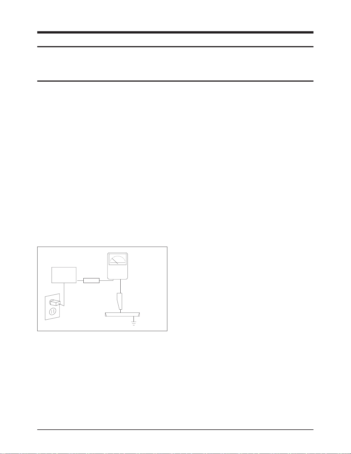
3. Check for Electricity Leakage (Figure 1-1)
Warning: Do not use an insulated transformer for checking the leakage. Use only those current leakage testers
or mirroring systems that comply with ANSIC 101.1 and
the Underwriter Laboratory's specifications (UL1410,
59.7).
Fig. 1-1 AC Leakage Test
4. Ahigh voltage is maintained within the specified limits
using safety parts, calibration and tolerances. When
voltage exceeds the specified limits, check each special
part.
5. Warning for Engineering Changes:
Never make any changes or additions to the circuit
design or the internal part for this product.
Ex: Do not add any audio or video accessory
connectors. This might cause physical damage.
Furthermore, any changes or additions to the original
design/engineering will invalidate the warranty.
6. Warning - Hot Chassis:
Some TV chassis are directly connected to one end of
the AC power cord for electrical reasons.
Without insulated transformers, the product can only be
repaired safely when the chassis is connected to the
earthed end of the AC power source.
To make sure the AC power cord is properly connected,
follow the instructions below. Use the voltmeter to
measure the voltage between the chassis and the
earthed ground. If the measurement is over 1.0V, unplug
the AC power cord and change the polarity before reinserting it. Measure the voltage between the chassis
and the ground again.
7. Some TV chassis are shipped with an additional
secondary grounding system. The secondary system is
adjacent to the AC power line. These two grounding
systems are separated in the circuit using an
unbreakable/unchangeable insulation material.
8. When any parts, material or wiring appear overheated or
damaged, replace them with new regular ones
immediately. When any damage or overheating is
detected, correct this immediately and make a regular
check of possible errors.
9. Check for the original shape of the lead, especially that
of the antenna wiring, any sharp edges, the AC power
and the high voltage power. Carefully check if the wiring
is too tight, incorrectly placed or loose. Never change the
space between the part and the printed circuit board.
Check the AC power cord for possible damages. Keep
the part or the lead away from any heat-emitting
materials.
Precaution
Samsung Electronics 1-1
To avoid possible damages or electric shocks or exposure to radiation, follow the instructions below with regard to safety,
installation, service and ESD.
1. Precaution
1-1 Safety Precautions
(READING SHOULD
DEVICE
UNDER
TEST
EXPOSED METAL
2-WIRE CORD
ALSO TEST WITH
PLUG REVERSED
(USING AC ADAPTER
PLUG AS REQUIRED)
TEST ALL
SURFACES
LEAKAGE
CURRENT
TESTER
NOT BE ABOVE
0.5mA)
EARTH
GROUND

10. Safety Indication:
Some electrical circuits or device related materials
require special attention to their safety features, which
cannot be viewed by the naked eye. If an original part is
replaced with another irregular one, the safety or
protective features will be lost even if the new one has a
higher voltage or more watts.
Critical safety parts should be bracketed with ( ).
Use only regular parts for replacements (in particular,
flame resistance and dielectric strength specifications).
Irregular parts or materials may cause electric shock or
fire.
Precaution
1-2 Samsung Electronics
!

1. The service instructions are printed on the cabinet, and
should be followed by any service personnel.
2. Make sure to unplug the AC power cord from the power
source before starting any repairs.
(a) Remove or re-install parts or assemblies.
(b) Disconnect the electric plug or connector, if any.
(c) Connect the test part in parallel with the electrolytic
capacitor.
3. Some parts are placed at a higher position than the
printed board. Insulated tubes or tapes are used for this
purpose. The internal wiring is clamped using buckles to
avoid contact with heat emitting parts. These parts are
installed back to their original position.
4. After the repair, make sure to check if the screws, parts
or cables are properly installed. Make sure no damage is
caused to the repaired part and its surroundings.
5. Check for insulation between the blade of the AC plug
and that of any conductive materials (i.e. the metal
panel, input terminal, earphone jack, etc).
6. Insulation Check Process: Unplug the power cord from
the AC source and turn the switch on. Connect the insulating resistance meter (500v) to the AC plug blade.
The insulating resistance between the blade of the AC
plug and that of the conductive material should be more
than 1 ㏁.
7. Any B+ interlock should not be damaged.
If the metal heat sink is not properly installed, no
connection to the AC power should be made.
8. Make sure the grounding lead of the tester is connected
to the chassis ground before connecting to the positive
lead. The ground lead of the tester should be removed
last.
9. Beware of risks of any current leakage coming into
contact with the high-capacity capacitor.
10. The sharp edges of the metal material may cause
physical damage, so ensure wearing protective gloves
during the repair.
Precaution
Samsung Electronics 1-3
Warning 1: First carefully read the "Safety Instruction" in this service manual.
When there is a conflict between the service and the safety instructions, follow the safety instruction at all times.
Warning 2: Any electrolytic capacitor with the wrong polarity will explode.
1-2 Servicing Precautions

1-3 Static Electricity Precautions
1. Some semi-conductive ("solid state") devices are
vulnerable to static electricity. These devices are known
as ESD. ESD includes the integrated circuit and the field
effect transistor. To avoid any materials damage from
electrostatic shock, follow the instructions described
below.
2. Remove any static electricity from your body by
connecting the earth ground before handling any
semi-conductive parts or ass'ys. Alternatively, wear a
dischargeable wrist-belt.
(Make sure to remove any static electricity before
connecting the power source - this is a safety instruction
for avoiding electric shock)
3. Remove the ESD ass'y and place it on a conductive
surface such as aluminum foil to prevent accumulating
static electricity.
4. Do not use any Freon-based chemicals.
Such chemicals will generate static electricity that
causes damage to the ESD.
5. Use only grounded-tip irons for soldering purposes.
6. Use only anti-static solder removal devices.
Most solder removal devices do not support an
anti-static feature. Asolder removal device without an
anti-static feature can store enough static electricity to
cause damage to the ESD.
7. Do not remove the ESD from the protective box until the
replacement is ready. Most ESD replacements are
covered with lead, which will cause a short to the entire
unit due to the conductive foam, aluminum foil or other
conductive materials.
8. Remove the protective material from the ESD
replacement lead immediately after connecting it to the
chassis or circuit ass'y.
9. Take extreme caution in handling any uncovered ESD
replacements. Actions such as brushing clothes or lifting
your leg from the carpet floor can generate enough static
electricity to damage the ESD.
Precaution
1-4 Samsung Electronics
CAUTION
These servicing instructions are for use by
qualified service personnel only.
To reduce the risk of electric shock do not
perform any servicing other than that contained in the
operating instructions unless you are qualified to do so.

Precaution
Samsung Electronics 1-5
1-4 Installation Precautions
1. For safety reasons, more than two people are required
for carrying the product.
2. Keep the power cord away from any heat emitting
devices, as a melted covering may cause fire or electric
shock.
3. Do not place the product in areas with poor ventilation
such as a bookshelf or closet. The increased internal
temperature may cause fire.
4. Bend the external antenna cable when connecting it to
the product. This is a measure to protect it from being
exposed to moisture. Otherwise, it may cause a fire or
electric shock.
5. Make sure to turn the power off and unplug the power
cord from the outlet before repositioning the product.
Also check the antenna cable or the external connectors
if they are fully unplugged. Damage to the cord may
cause fire or electric shock.
6. Keep the antenna far away from any high-voltage cables
and install it firmly. Contact with the high-voltage cable or
the antenna falling over may cause fire or electric shock.
7. Check the basics of the screen test.
- Image position/size, Tilt adjustment
Product Specification
Samsung Electronics 2-1
2. Product Specification
2-1 Product Features
Block Specfication Core Parts Remark
CRT - 21" AK CRT Normal CRT
RF Part - Analog Tuner TUNER-F/S;TDQ-6F/13F2S,NTSC,
Power - Input voltage:AC110V KA5Q0765RTH-YDTU
Video - NTSC TDA9377PS/N3/A
Audio
- Output:10W x 2
- Function:Melody on /off,Turbo Sound
TDA7297SA
Cabinet - Front and back cabinet K40 design applied Material: HIPS
Other
- Development Level : Level 4
- ProtoType Model: CL21K40MQGXRCL
■ Core Parts Functions
- TDA9377PS/N3/A: CVBS, Video and Sound Signal Processing , Controls the operation of the overall main board.
- TDA7297SA: Sound Signal Amplify
- KA5Q0765RTH-YDTU : Power Supply TR
- TUNER-F/S;TDQ-6F/13F2S(tuner) : RF signal processing , Output IF signal

Product Specification
2-2 Samsung Electronics
2-2 Key Features
Model CL-21K40MQ
Voltage AC110V
Frequency of Operation 60HZ
Dimensions (mm/inches)
622 x489.5x472
24.48x19.25x18.58
Weight (Kg/ lbs) 25.8/56.6
■ H/W Configuration
- 21 AK CRTadopted
■ Picture
- System : SECAM/NTSC4.43/NTSC3.58
- Digital Noise Reduction
■ Sound
- Sound System : Line Stereo
- Output : 10W+10W
- AVL, Melody , Auto Stereo, Auto Mute
- Turbo Sound
■ Feature
- Language : Multi
- Picture Size : Zoom/3:4
- Auto Program
- Sleep Timer : 180 Min
- Clock
- Child Lock
■ Power Comsumption
- Max power:110W

Product Specification
Samsung Electronics 2-3
2-3 Specifications Analysis
Model 21M16 CL-21K40MQ
Chassis KS9A KS9C
Design
Picture
Screen Size 21" 21"
Pure Flat CRT
○ ○
DNIe Jr. X X
Comb Filter - -
Velocity Modulation - -
Video Noise Reduction X
○
Auto Kinetic Bias
○ ○
Color Tone Control
○ ○
Tilt Control - -
Picture Mode 4 Mode 4 Mode
Sound
MTS/SAP
○
Output Power(RMS) 7Wx2 10W x 2
Tweeter - -
BBE - -
Surround X X
Sound Mode 5 Mode 5 Mode
Graphic Equalizer - Sub-Woofer Speaker - Auto Volume Leveler
○ ○
Melody On/Off
○ ○
Turbo Sound
○ ○
Convenience
PIP X X
Plug & Play
○ ○
Zoom Mode
○ ○
OSD Demo X X
OSD Language Multi Multi
Previous Channel
○ ○
Closed Caption
○ ○
On/Off Timer
○ ○
Sleep Timer
○ ○
Auto Power Off
○ ○
Clock
○ ○
Channel Scan - -
Self-diagnostic System X X
Remote Control TM75 TM75
Remote Surf X X
Channel Labelling X X
Blue Screen
○ ○
Rack - -
Voltage Voltage 100~240 100~240
Power
Consumption
Stand-by
uner 9 W under 6W
Jacks
RF Input R1 R1
A/V Input S1/R1 S1/R2
Monitor Output R1 R1
S-VHS Input - -
Headphone S1 S1
DVD Input -
○
PC Input(VGA) - -
Product Specification
2-4 Samsung Electronics
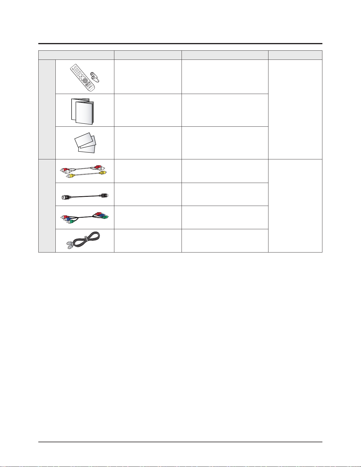
2-4 Accessories
Accessories Item Item code Remark
SuppliedAccessories
Remote Control
AAAAlkaline Battery (2)
AA59-00385B
4301-000121
Samsung Service
center
Owner's Instructions
Safety Guide Manual
AA68-03810B
AA68-03242F
Warranty Card 6801-001058
Accessories that canbepurchased
additionally
Video Cable /
Audio Cable
-
Internal shopping mall
Antenna Cable -
Component Cable -
Optical Cable -

Alignment & Adjustment
Samsung Electronics 3-1
3. Alignment & Adjustment
3-1 Service Instruction
1. General Adjustment :
In general, a color TV can provide ideal visual quality by adjusting the basic settings such as the vertical size, horizontal size,
focus, etc.
Display a black and white picture on the screen to check if the picture is clearly displayed.
If there are some 'spotted' points on the screen when displaying a black and white picture, degauss the screen using the
degauss coil. If the spotted points remain, re-adjust the purity and the convergence. This completes the basic performance
examination.
Notice.
■ These adjustments and the check list are only applied to KS9C chassis-applied models.
■ use 110v for the measurement set. It is recommended using an
insulation transformer when supplying power to the set so as to prevent shock to the set or to yourself.
■ These adjustment specifications have been created on the basis of the domestic KS9C chassis-applied remote
control model. Some of the contents may be changed subject to the sales location and the product specifications.
2. When replacing the Main Board :
Focus adjustment, screen voltage setting and W/B adjustment are all required.
3. When replacing the CRTAss'y : No adjustments required.
Alignment & Adjustment
3-2 Samsung Electronics
3-2 How to Access Service Mode
MENU Show all menus
▲ / ▼
Move the cursor to select an item.
◀ / ▶
Adjust the selected configuration value
1. To enter Service Mode, press the keys on the remote control according to the following sequence. (in Stand-by status)
Info → Menu →MUTE→ power On
※ When failing to enter Service Mode, repeat the procedure above.
2. The initial screen of Service Mode.
3. Functions of the Keys within Service Mode
ADJUST
OPTION
G2-ADJUST
CHCKSUM
RESET
T-FMTNUS

Alignment & Adjustment
Samsung Electronics 3-3
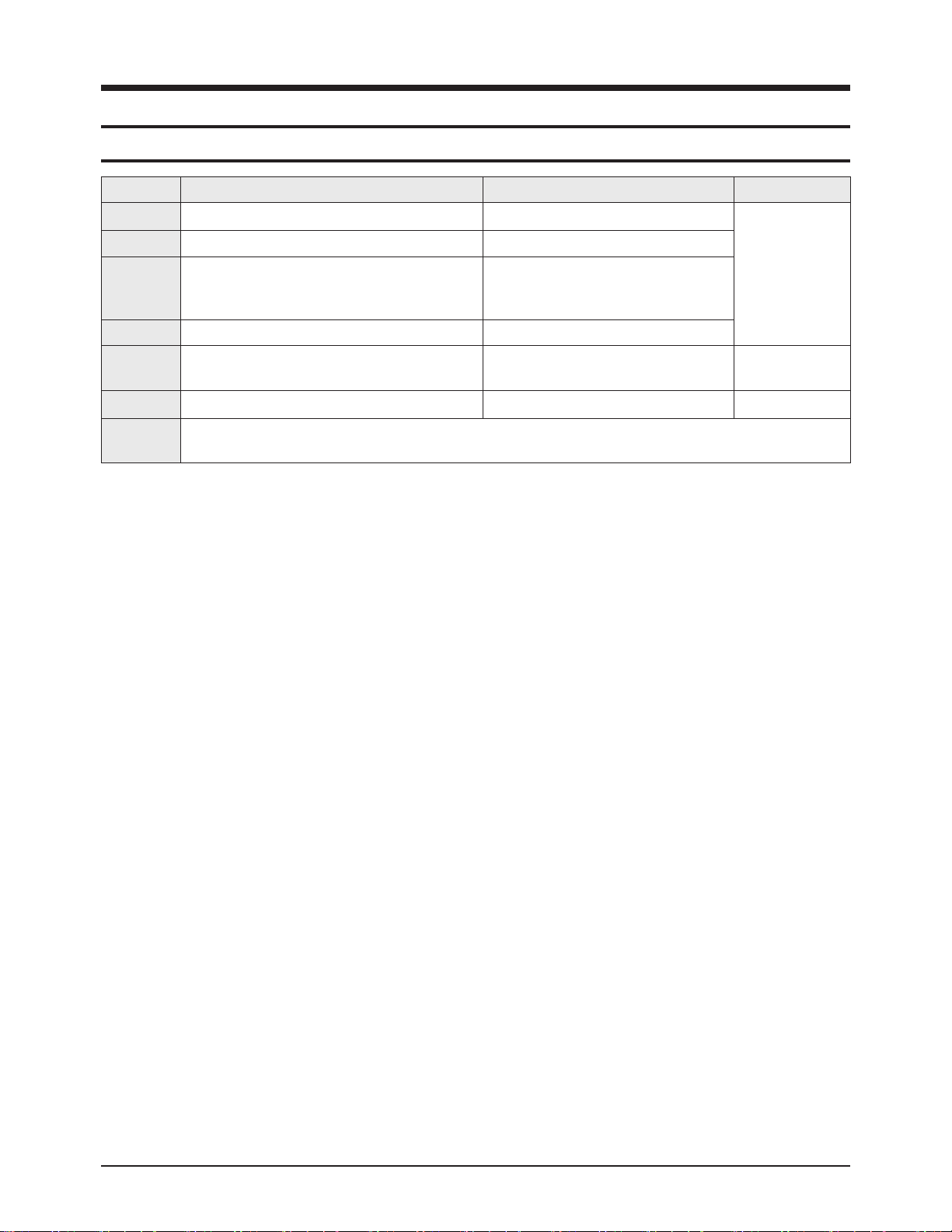
3-3 Factory Data
★ The underlined are items applied during the service adjustment. None of the others should be adjusted.
1.T-FMTNUS
No Item Adjust/Fix Initial Remark
1 HS Adjust 37
2 VA Adjust 34
3 VSL Adjust 30
4 VS FIX 31
5 AGC Adjust 33
6 CDL FIX 9
7 SCT Adjust 10
8 SBT Adjust 7
9 BLR Adjust 28
10 BLB Adjust 43
11 RG Adjust 30
12 GG FIX 32
13 BG Adjust 46
14 SC FIX 29
15 STT FIX 29
16 AKB FIX 0
17 NDL FIX 1
18 NSR FIX 5
19 VOL FIX 10
20 MVOL FIX 7
21 RPO0 FIX 1
22 RPO1 FIX 1
23 CAP FIX 12
24 FMWS FIX 0
25 AGCS FIX 1
26 OMD FIX 15
27 SCL FIX 3
28 PWL FIX 13
29 MUS FIX 1
30 SCBT FIX 40
31 SSP FIX 5
32 DNSR FIX 17
33 DSBT FIX 0
34 DCDL FIX 6
35 DBLR FIX 32
36 DBLB FIX 32
37 DSK FIX 0
Alignment & Adjustment
3-4 Samsung Electronics
2.Option
3.White Balance
No Item Initial 21"FLAT Remark
1 Video Mute Off Off
Video Mute time between the Channel
changes
2 Audio STEREO STEREO Audio MONO/STEREO Option
3 2ND SIF EXTERNAL EXYERNAL SIF Option
4 Auto Power Off Off
Turns on automatically when the Master
Power is turned ON
5 Audio Mute On On
Mutes the Audio when the there is no
source signal
6 Start Language English English
Preset OSD (On-Screen Display) laguage
at time of purchase
7 Hotel Mode Off Off
8 Blue Screen On On
Blue Screen when there is no source signal
9 V-Chip Off Off
10 AV Option AV1/2/DVD/SV AV1/2/DVD Back Jack Option
11 AFN Off Off
No Item 21"FLAT Remark
1 Hight Light 275/265/45FL
2 Low Light 275/265/1.5FL
Alignment & Adjustment
Samsung Electronics 3-5

Alignment & Adjustment
3-6 Samsung Electronics
3-4 Service Adjustment
3-4-1 Adjusting the Picture Size
■ Since the KS9C chassis has the deflection settings data within the Factory Data, the picture size has to be adjusted when
replacing Main Board, according to the following procedures.
① Display the Lion pattern.
② Press "Power Off →MUTE→1→8→2→Power On "
using the remote control and enter Factory Mode.
③ Enter Deflection Mode.
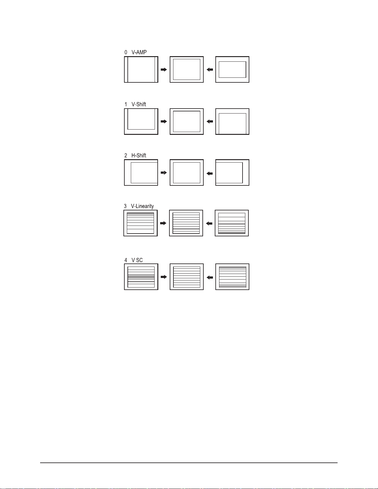
④ Adjust the VA, VS,VSL and HS items so
that the width becomes 5 and the height becomes 4.
Alignment & Adjustment
Samsung Electronics 3-7
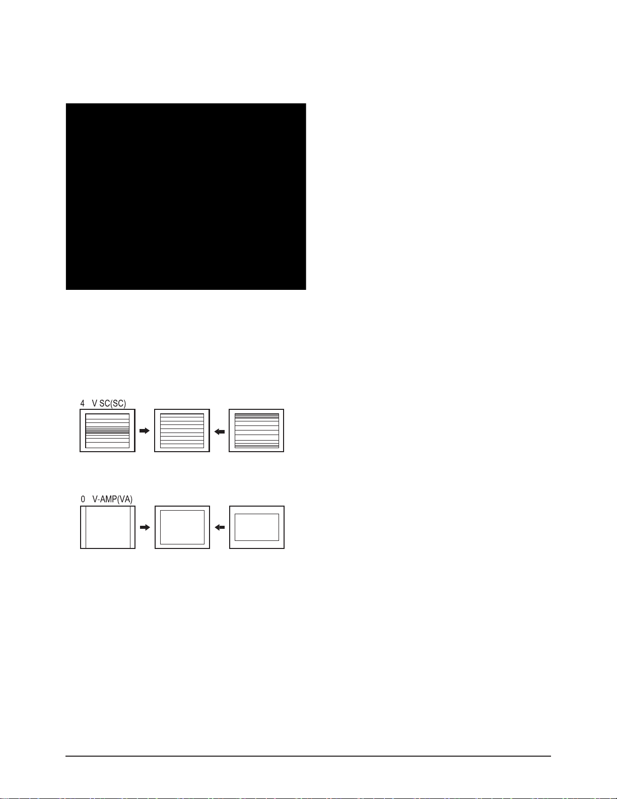
3-4-2 Adjusting the Picture Straight Lines
① Display the Cross Hatch pattern.
② Adjust settings other than VA,VH and HS so that straight lines are displayed without curves.
④ When the adjustments are complete, display the Lion pattern and check that the picture size has not been changed.
If there is no change, finish the adjustments.
③ Adjust the V-Linearity and V-SC settings so that the
intervals of the horizontal lines become uniform.
Alignment & Adjustment
3-8 Samsung Electronics
3-5 Replacements & Calibration
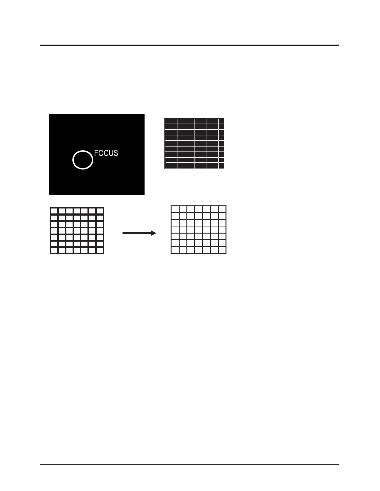
3-5-1 Adjusting the Focus
1. Display the CROSS Hatch pattern.
2. Turn the Focus clockwise to the optimal position.
3. Slowly turn the Focus clockwise so that the cross line is the most clearly displayed.

Alignment & Adjustment
Samsung Electronics 3-9
3-5-2 Adjusting the Screen Voltage
1. Select "Power Off →MUTE→1→8→2→Power On " to enter Service Mode.
2. Turn to toshiba pattern
3. Use remocon come into " G2 Adjust" mode by hand or automatically.
4. Turn Screen VR of FBTand confirm the characters below changed to GREEN.
 Loading...