How it Works
Log In / Sign Up
Buy Points
How it Works
FAQ
Contact Us
Questions and Suggestions
Users
Samsung
Loading...
C
CL15A8L7X-GSU
CL15A8L7X-RCL
2
CL15A8L7X-STR
2
CL15K5MN
5
CL15K5MNFXRCL
CL15K5MNFX-XAP
CL17M2
CL17M2MQ
2
CL17M2MQZX
2
CL17M2MQZX-STR
2
CL17M2MQZX-XAO
CL17M6
CL17M6MQ
2
CL17M6MQFX-RCL
2
CL17M6MQFX-XAP
CL21A
CL21A11MQKX
CL21A11MQKXXAX
3
CL21A1F0
CL21A550ML
CL21A551
CL21A551ML
3
CL21A551MLMXZX
CL21A730
2
CL21A730EQ
4
CL21A750
2
CL21A8W
3
CL21A8W7X-DRI
4
CL21A8W7X-GSU
2
CL21A8W7X-RCL
2
CL21A8W7X-STR
2
CL21A8W7X-XAP
5
CL21A9W7X-XAX
5
CL21AE0
4
CL21AF0
3
CL21AJ0
3
CL21AM0
4
CL21B501
CL21B501HLMXZS
2
CL21BA0
CL21BF0
CL21BH0
2
CL21C650MLMXZD
CL21K30
2
CL21K30M16
2
CL21K30MQ
3
CL21K30MQ6TXAP
CL21K30MQ6XXAO
CL21K30MQ6XXAP
CL21K3W
CL21K3WDX-STR
CL21K40
CL21K40MQGXXAZ
CL21K5MN6X-RCL
CL21K5MQ
7
CL21K5MQ6X-XAX
CL21M16MJ
6
CL21M16MJZTXAP
CL21M16MNZXBDB
2
CL21M16MNZXXAO
CL21M16MNZXXAX
3
CL21M2
4
CL21M21
7
CL21M21EQ2**A SERIES
CL21M21MQ2**AZ
CL21M21MQUXXAZ
2
CL21M21PQ
3
CL21M2MQ2X-XAX
CL21M40
CL21M40MQGXXAO
3
CL21M5W
3
CL21M6
5
CL21M6MQ2*AZ
CL21M6MQ2 SERIES
CL21M6MQ6X/XAP
2
CL21M6W
5
CL21M6WKX
CL21M6WKXAO
CL21M6WKX-RCL
3
CL21M6WKX-STR
2
CL21M6WKX-XAO
5
CL21M6WKX-XAP
2
CL21M6WKX-XAX
CL21M6XAO
CL21N11
CL21N11MJZXXAX
CL21N11MQ
CL21N11MQUXXAZ
2
CL21S8MQ
3
CL21S8MQU
2
CL21S8W
6
CL21S8W7X
CL-32Z40DS
4
CL-34A10PQ
6
CL-34M30HS
3
CL-34M9P
4
CL-34Z7HE
4
CL-633BW
CL-765DW
CL-766DW
Loading...
Loading...
Nothing found
CL21C650MLMXZD
Schematic
45 pgs
17.13 Mb
0
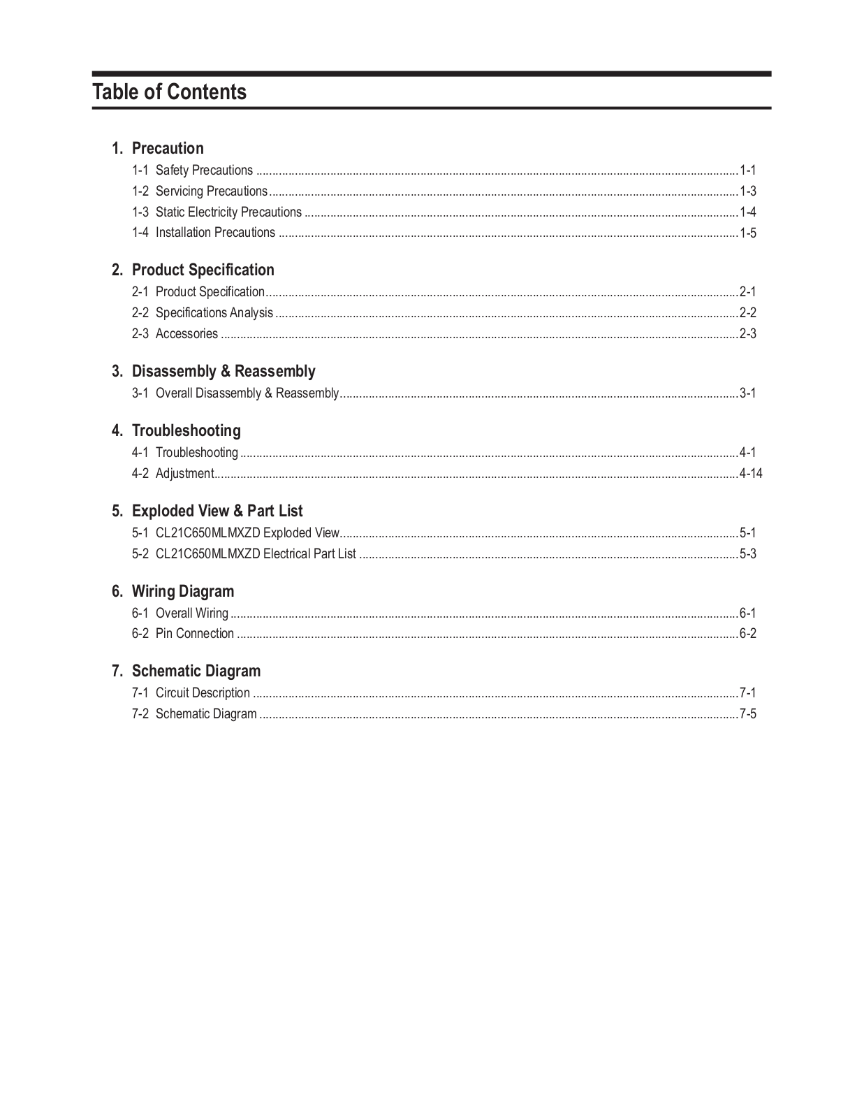
Table of contents
Loading...
Samsung CL21C650MLMXZD Schematic
...
Samsung Schematic
Download
Specifications and Main Features
Frequently Asked Questions
User Manual
Download
Loading...
+
31
hidden pages
Unhide
You need points to download manuals.
1 point = 1 manual.
You can buy points or you can get point for every manual you upload.
Buy points
Upload your manuals
 Loading...