

Samsung CKG7507 Troubleshooting

CKG7507L 7-1
7 Troubleshooting
Notes: 1. If a picture does not appear, fully rotate the brightness and contrast controls clockwise and reinspect.
2. Check the following circuits.
• No raster appears: Power circuit,Horizontal output circuit, H/V control circuit, and H/V output circuit.
• High voltage develops but no raster appears: Video output circuits.
• High voltage does not develop: Horizontal output circuits.
Check the Fuse, Bridge Diodes (D601~D604),
IC601, C617 and D614.
Check the Q503, Q504 and those are related High
Voltage control circuits. (IC501, Q510, Q501,
Q502, Q506, D508, D517 and D524)
7-1 No Power
Does proper DC 110-366 Volts
appear between the positive and
negative poles of C606?
Does the appear 45V at D617’s
Cathode pin? (the condition L501’s
are pin is desoldered)
Yes
No
Check D605, C616, C618, components in primary
part, the power feedback circuit (IC602, IC603,
and its related circuits), D617, D618, D610, D615,
D612, D620, D619, IC606 and IC607.
Does the appear 2’nd voltage
of T601 (45V, 72V, 14.7V and so on)?
(The condition BD602, BD603,
JW71, JW63 are desoldered)
Yes
No
Yes
Check the Q406, Q403, Q411 and those are
related Horizontal control circuit. (IC401, IC402,
Q404, Q401, Q402, Q405, Q408 and Q409)
Does the appear 45V at D617’s
Cathode pin? (the condition L403’s
are pin is desoldered)
Yes
No
No
Replace the IC301.
Does the appear 45V at D617’s
Cathode pin? (the condition
JW71, JW63 are desoldered)
Yes
No
Check the IC102, IC101 and another components
in Video Part (IC103, IC104, etc).
Does the appear 45V at D617’s
Cathode pin? (the condition
CN102 is disconnected)
No

7 Troubleshooting
7-2 CKG7507L
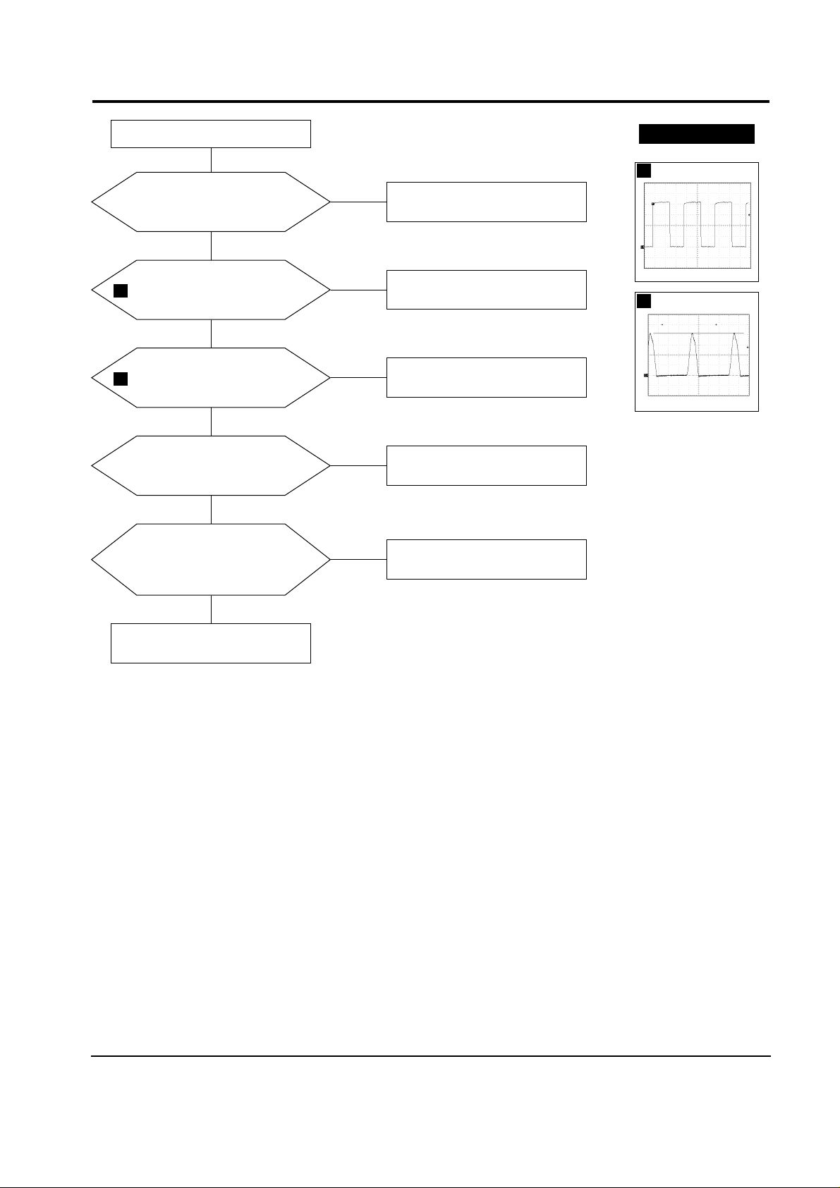
7-3 Vertical Line on CRT
Does the drive pulse
appear at the emitter of
Q401?
Yes
Replace Q403 or check its
related circuits.
(C416 and T401)
No
WAVEFORMS
43
Check Q411 and D408.
Does the drive output
pulse appear at the Collector
of Q403?
Yes
17
Check IC402 and its application.
No
Does the pulse appear at
Gate of Q411?
Yes
Replace IC301 and check its related
Vertical IC’s application.
Check the –12V Line at power
secondary part. (D615, C620)
Check R303 and R310.
Replace IC401.
7-2 Horizontal Line on CRT or Rainbow Color on the Screen
The first of all you must check
CN301. Does the –12V appear at
Pin 4 of IC301?
Does the pulse appear at Pin 5
of IC301?
Yes
No
No
Yes
Yes
Does the sawteeth wave appear
at the Pin 9 of IC401?
No
WAVEFORMS
10
7
14
15.8 V (Q411, Gate)
CH1 P-P = 15.8 V CH1 RMS = 8.37 V
14
54.8 V (IC301, #5)
CH1 P-P = 54.8 V CH1 RMS = 6.38 V
10
2.80 V (IC401, #9)
CH1 P-P = 2.80 V CH1 RMS = 3.469 V
7
140 V (Q403, Collector)
CH1 P-P = 140 V CH1 RMS = 52.7 V
17
7.12 V (Q401, #Emitter)
CH1 P-P = 7.12 V CH1 RMS = 4.836 V
43
7 Troubleshooting
CKG7507L 7-3
Change FBT.
Check the power supply circuits.
Power indicator is green
Check Q404 and its related circuits.
Does the +B output voltage
appear at the secondary side of
T601? (45 V, 72 V, 14.7 V, etc)
Does the output
pulse appear at
Pin 18 of IC401?
Check IC501 and its application
circuits.
Does the pulse appear at
the Collector of Q503?
7-4 No Raster (1)
Yes
No
Yes
No
Yes
No
Does the DC Voltage (about 10V)
appear at Pin 7 of IC502?
Yes
Yes
Replace IC502.
No
Check HV protection circuits and
IC502’s application circuits.
No
WAVEFORMS
3
26
Does the DC Voltage
(200V over) appear at HV_ADJ
point (The condition Pin 7 of IC502
is desoldered)?
8.56 V (IC401, #18)
CH1 P-P = 8.56 V CH1 RMS = 5.900 V
3
856 V (Q503, Collector)
CH1 P-P = 856 V CH1 RMS = 251.2 V
26
 Loading...