


Samsung A100 Service Manual Trouble Shooting

7. Trouble Shooting
• Power On Failure.
• SIM Recognition Failure.
• Battery Charging Failure.
• Audio Failure ( Microphone, Speaker )
• Keypad Failure
• Ring Indicator Failure
• Back Light Failure
• Call Failure ( DCS, GSM Rx and Tx part )
7.1 Flow Chart of Troubleshooting
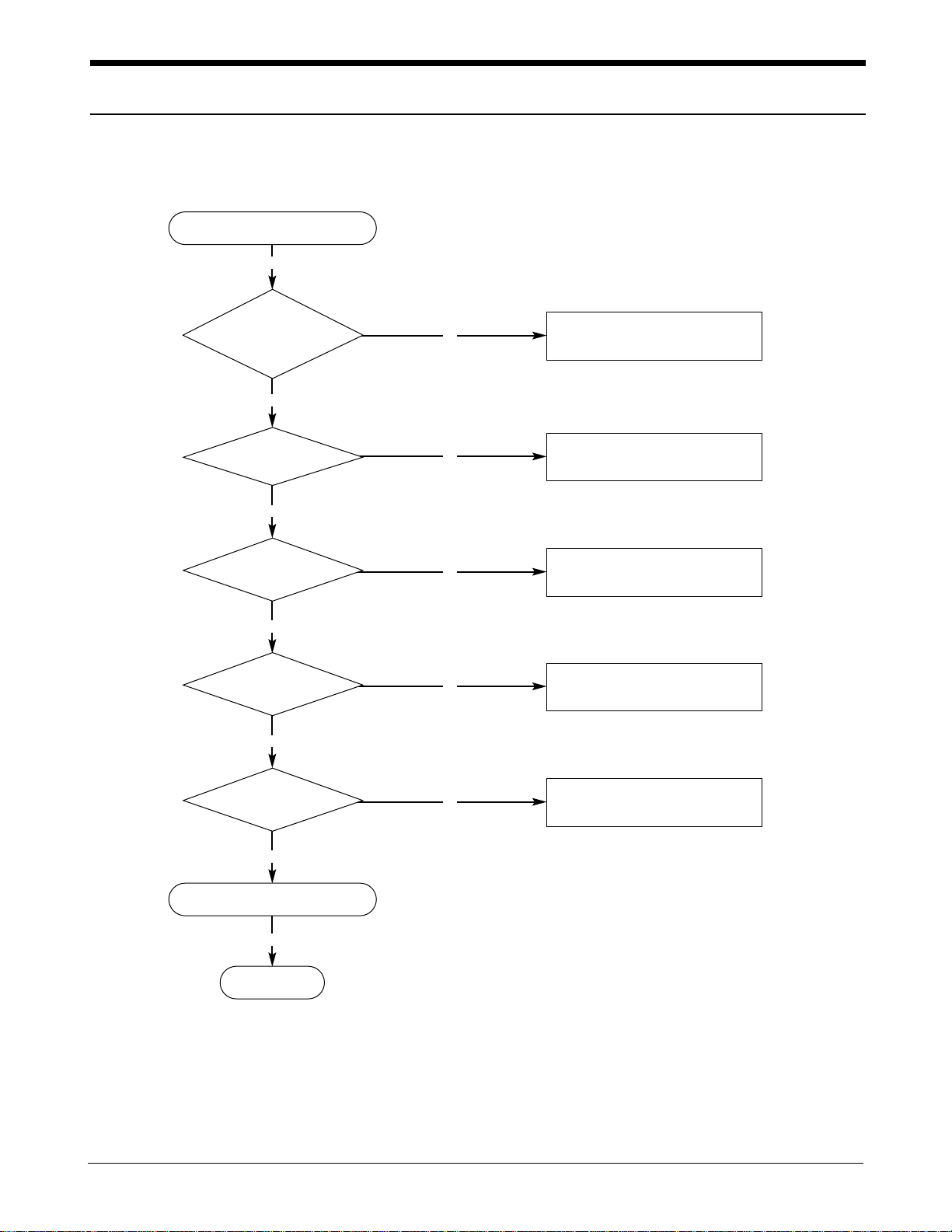
7.1.1 SGH-A100 Power ON
N
‘POWER ON’ does not work
Y
Y
Check the current
consumption more than
100 mA
Download again
N
Y
Check the
Battery Voltage more
than 3.3V
Charge the Battery
N
Y
Check the pin
38 of U401 is more than
3.2 V
Check to the path from CN601 to pin
38 of U400 and keypad
N
Y
U401 pin 28,30
= 2.8V
Change U401
N
Y
END
Y
Check the clock signal
at R116
Check the clock generation circuit
(related to U401 and OSC101)
Check the initial operation
Flow Chart of Troubleshooting
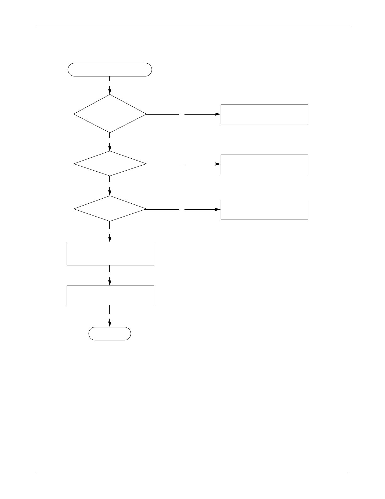
7.1.2 SGH-A100 Initial
N
Initial Failure
Y
Y
Check the “Reset_B”
signal at the pin 2 of
U401 is “High”
Check the U101 (IA)
N
Y
Check the pin 10
of U401 is “High”
Check the U201 (M46)
N
Y
Check the pin 11 of U401
is “High”
Check the U401 (PMIC)
Y
Check the connections and
initialization using Factory
Test Program
END
Y
Check LCD connector CN603,
and resolder bridge
Flow Chart of Troubleshooting
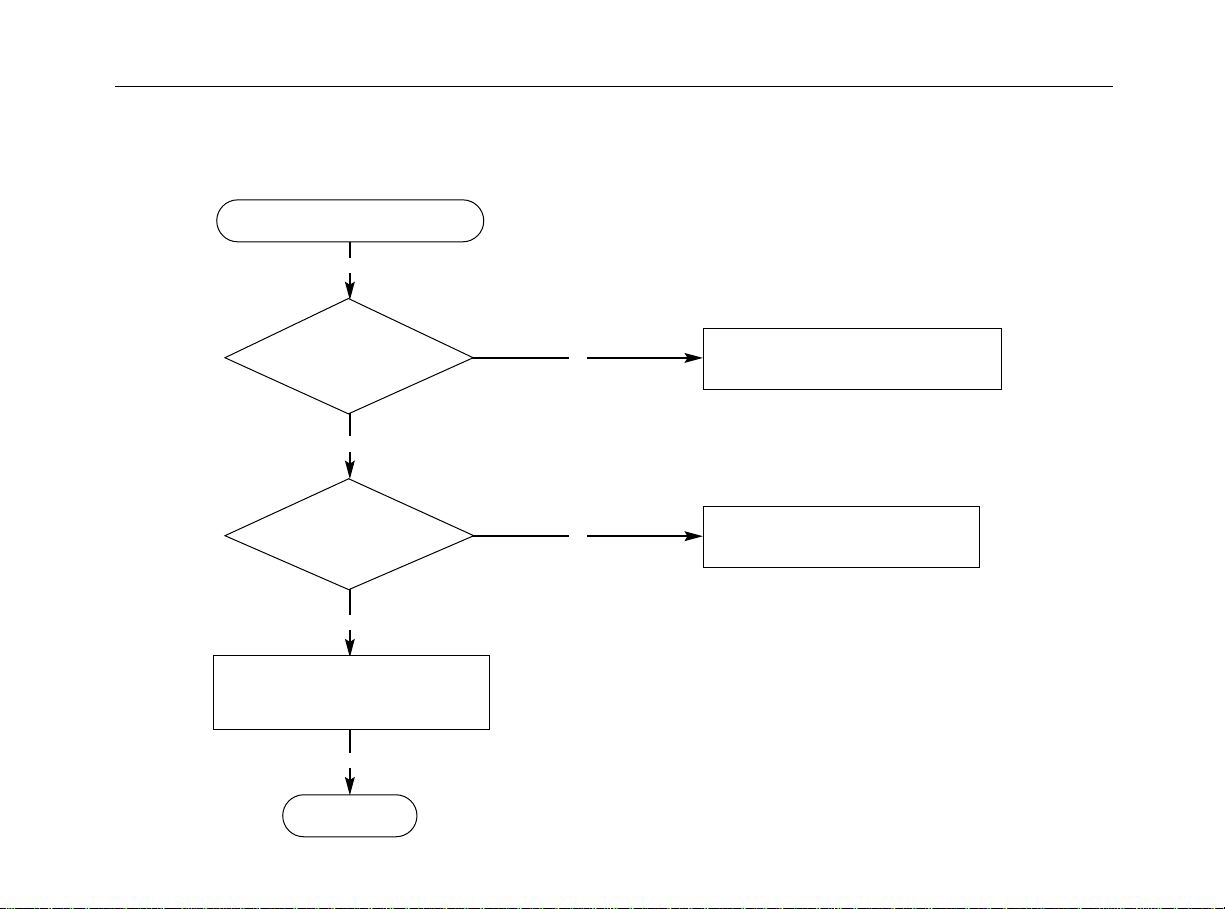
7.1.3 SGH-A100 SIM Part
Phone can’t access SIM card
Y
Check the pin 1, 5 of
CN401. voltage is 2.8V ?
Y
Check the SIM
connector’s CN401
Connection to
SIM card
Y
Check the circuit around U513
(Serial EEPROM) and data stored in it
Y
END
N
N
Check the SIM related circuit of the U401
Resolder CN401
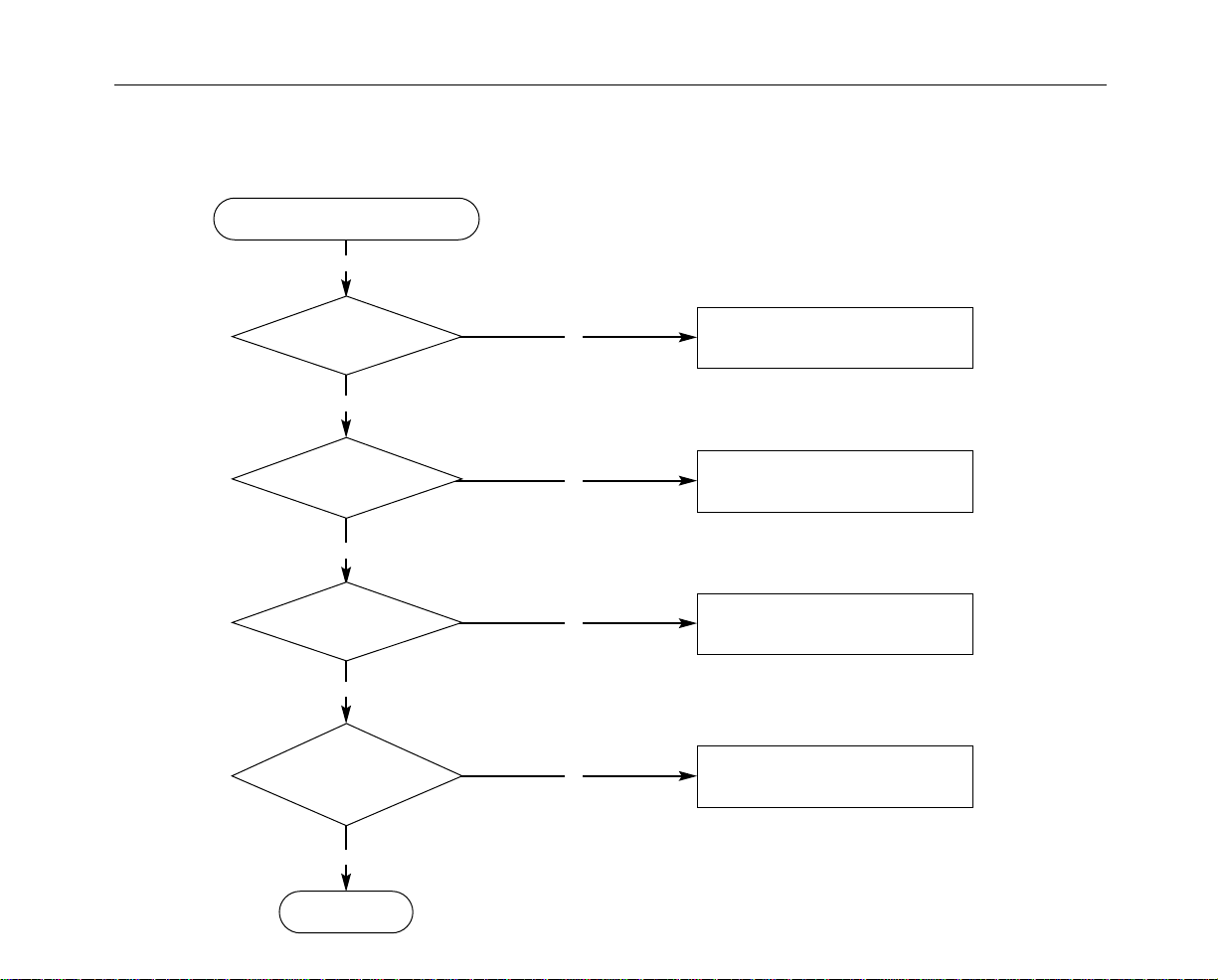
7.1.4 SGH-A100 Charging Part
Abnormal charging part
Y
Flow Chart of Troubleshooting
the pin 9 of CN601
Check
is around 12V
Y
Check the pin 2 of U609
is “Low”
Y
Check the
pin 3 of U607 is more
than 0.5V
Y
Check the
Voltage of pin 10 of
U605 is between 3.2 V
and 4.2 V
Y
N
N
N
N
Replace TA
Check the U201
Resolder R638, R643,L607
Resolder ZD609
END