

Samsung 732, 932 Service manual
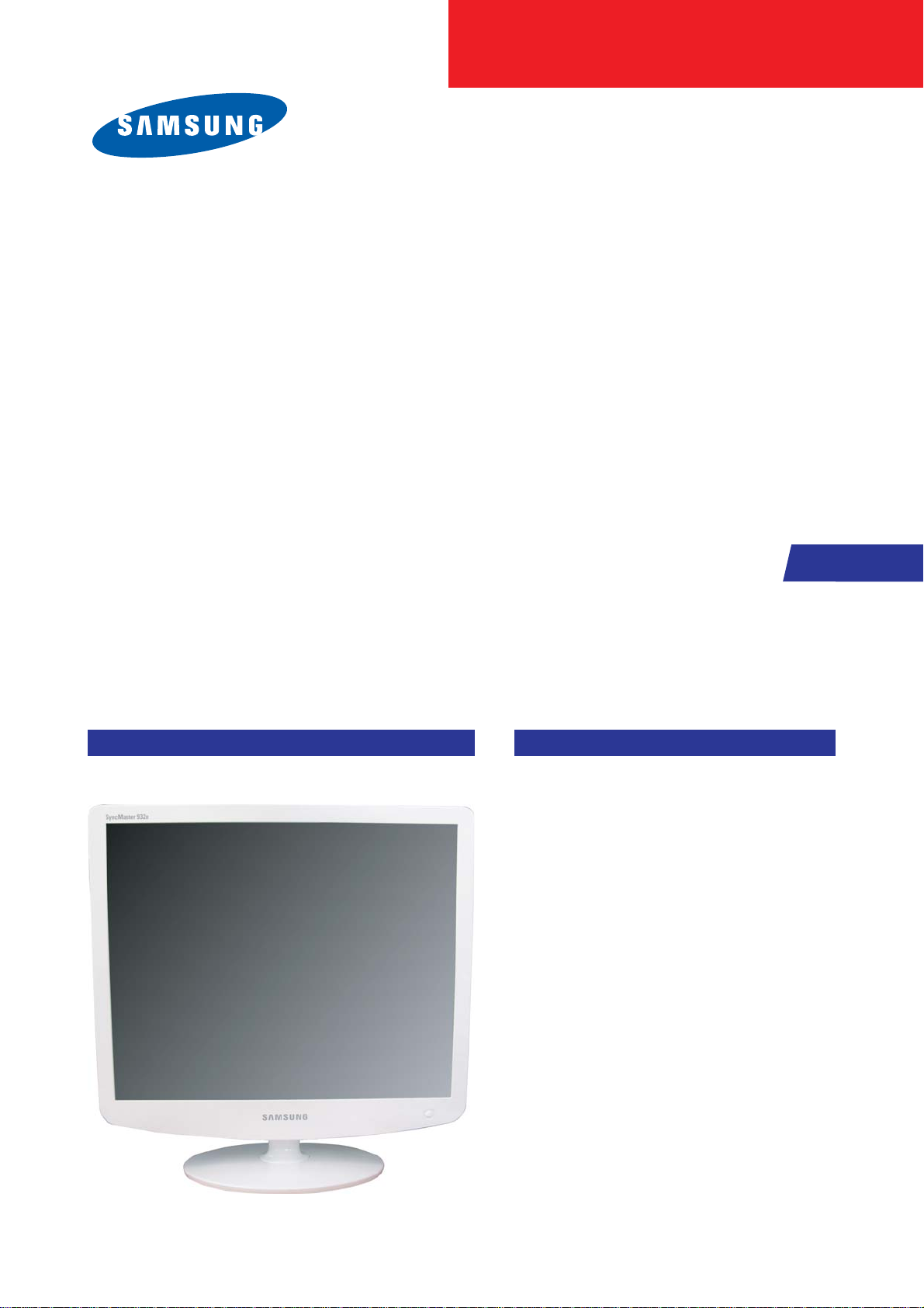
SERVICE
Manual
TFT-LCD Monitor
Fashion Feature
LCD-Monitor
Chassis Model
LS17PEA 732N
732NPLUS
LS19PEB 932B
932BPLUS
LS19PEA 932NPLUS
-Lustrous/Colorful Appearance (Design)
-Integrated UI applied
-Built-in Scaler Sync Separator
-Connectivity :
LS17PEA, LS19PEA - Analog (15p Dsub)
LS19PEB - Analog (15p Dsub),
Dual (24p DVI-D)
-Power Consumption : 17"(34W), 19"(38W)
-DPMS : under 1 W (230Vac)

ii
Copyright
©2006 by Samsung Electronics Co., Ltd.
All rights reserved.
This manual may not, in whole or in part, be copied,
photocopied, reproduced, translated, or converted to
any electronic or machine readable form without prior
written permission of Samsung Electronics Co., Ltd.
LS17PEA/LS19PEA/LS19PEB Service Manual
First edition February 2006.
Printed in Korea.
Trademarks
Samsung is the registered trademark of Samsung
Electronics Co., Ltd.
LS17PEA/LS19PEA/LS19PEB and MacMaster Cable
Adapter are trademarks of Samsung Electronics Co.,
Ltd.
Macintosh, Power Macintosh are trademarks of Apple
Computer, Inc.
All other trademarks are the property of their respective
owners.

11. Precautions
………………………………………………………………………………………………………………………………………
11-1
1-1 Safety Precautions ……………………………………………………………………………………………………………………… 1-1
1-2 Servicing Precautions …………………………………………………………………………………………………………………… 1-2
1-3 Electrostatically Sensitive Devices (ESD) Precautions ……………………………………………………………………………… 1-2
1-4 Installation Precautions ………………………………………………………………………………………………………………… 1-3
2
2. Product specifications
…………………………………………………………………………………………………………………………
22-1
2-1 Fashion Feature…………………………………………………………………………………………………………………………… 2-1
2-2 LS17PEA Specifications ………………………………………………………………………………………………………………… 2-1
2-3 LS19PEB Specifications ………………………………………………………………………………………………………………… 2-2
2-3 LS19PEA Specifications ………………………………………………………………………………………………………………… 2-4
2-4 Spec Comparison ………………………………………………………………………………………………………………………… 2-5
2-5 Option Specification ……………………………………………………………………………………………………………………… 2-6
3
3. Alignments and Adjustments
…………………………………………………………………………………………………………………
33-1
3-1 Required Equipment …………………………………………………………………………………………………………………… 3-1
3-2 Automatic Color Adjustment …………………………………………………………………………………………………………… 3-1
3-3 DDC EDID Data Input …………………………………………………………………………………………………………………… 3-1
3-4 OSD Adjustment When Replacing Panel ……………………………………………………………………………………………… 3-1
3-5 OSD Adjustment When Replacing Lamp Only ………………………………………………………………………………………… 3-1
3-6 Service Function Spec. ………………………………………………………………………………………………………………… 3-2
3-7 How to execute DDC …………………………………………………………………………………………………………………… 3-4
3-8 How to execute MCU Code ……………………………………………………………………………………………………………… 3-5
4
4. Troubleshooting
………………………………………………………………………………………………………………………………
44-1
4-1 No Power) …………………………………………………………………………………………………………………………………4-1
4-2 No Video (ANALOG) ……………………………………………………………………………………………………………………… 4-2
4-3 No Video (DIGITAL) ……………………………………………………………………………………………………………………… 4-4
5
5. Exploded View and Parts List
………………………………………………………………………………………………………………
55-1
6. EElectrical Parts List
……………………………………………………………………………………………………………………………
6
6-1
Contents

77. Block Diagram
…………………………………………………………………………………………………………………………………
77-1
7-1 Power Tree ………………………………………………………………………………………………………………………………… 7-1
7-2 Main Board Part ( LS17PEA, LS19PEA) ……………………………………………………………………………………………… 7-2
7-3 Main Board Part ( LS19PEB) …………………………………………………………………………………………………………… 7-3
7-4 IP Board Part (SMPS Part) ……………………………………………………………………………………………………………… 7-4
7-5 IP Board Part (Inverter Part) …………………………………………………………………………………………………………… 7-5
8
8. Wiring Diagram
…………………………………………………………………………………………………………………………………
88-1
8-1 Wiring Diagram LS17PEA, LS19PEA ………………………………………………………………………………………………… 8-1
8-2 Wiring Diagram LS19PEB ……………………………………………………………………………………………………………… 8-2
9
9. Schematic Diagrams
……………………………………………………………………………………………………………………………
99-1
9-1 Schematic Diagrams (LS17PEA, LS19PEA) ………………………………………………………………………………………… 9-1
9-2 Schematic Diagrams (LS19PEB) ……………………………………………………………………………………………………… 8-2
1
10. Operating Instructions and Installation ………………………………………………………………………………………………………10-1
10-1 Front …………………………………………………………………………………………………………………………………… 10-1
10-2 Rear……………………………………………………………………………………………………………………………………… 10-2
10-3 Connecting the monitor ……………………………………………………………………………………………………………… 10-3
1
11. Disassembly and Reassembly
………………………………………………………………………………………………………………
111-1
11-1 Disassembly …………………………………………………………………………………………………………………………… 11-1
11-2 Reassembly …………………………………………………………………………………………………………………………… 11-6
1
12. PCB Diagram
…………………………………………………………………………………………………………………………………
112-1
12-1 Main PCB (LS17PEA, LS19PEA) …………………………………………………………………………………………………… 12-1
12-2 Main PCB (LS19PEB) ………………………………………………………………………………………………………………… 12-2
1
13. Circuit Descriptions
……………………………………………………………………………………………………………………………
113-1
13-1 Overall Block Structure ……………………………………………………………………………………………………………… 13-1
13-2 Trouble Shooting ……………………………………………………………………………………………………………………… 13-5
13-3 IP BOARD(Power) Schematic Diagrams …………………………………………………………………………………………… 13-8
13-4 IP BOARD(Inverter) Schematic Diagrams ………………………………………………………………………………………… 13-9
1
14. Reference Infomation
14-1 Technical Terms ……………………………………………………………………………………………………………………… 14-1
14-2 Pin Assignments ……………………………………………………………………………………………………………………… 14-3
14-3 Timing Chart …………………………………………………………………………………………………………………………… 14-4
14-4 Preset Timing Modes ………………………………………………………………………………………………………………… 14-5
14-5 Panel Description ……………………………………………………………………………………………………………………… 14-6
Contents
Samsung Electronics Co.,Ltd.
416, Maetan-3Dong, Yeongtong-Gu, Suwon City,
Gyeonggi-Do, Korea, 443-742
Printed in Korea
P/N : BN82-00138H-02
URL : http://itself.sec.samsung.co.kr/
-This Service Manual is a property of Samsung
Electronics Co., Ltd.
Any unauthorized use of Manual can be punished
under applicable International and/or domestic
law.
1 Precautions
1-1
1-1-1 Warnings
1. For continued safety, do not attempt to modify the circuit
board.
2. Disconnect the AC power and DC power jack before
servicing.
1-1-2
Ser vicing the LCD Monitor
1. When servicing the LCD Monitor, Disconnect the AC
line cord from the AC outlet.
2. It is essential that service technicians have an accurate
voltage meter available at all times. Check the
calibration of this meter periodically.
1-1-3 Fire and Shock Hazard
Before returning the monitor to the user, perform the
following safety checks:
1. Inspect each lead dress to make certain that the leads are
not pinched or that hardware is not lodged between the
chassis and other metal parts in the monitor.
2. Inspect all protective devices such as nonmetallic control
knobs, insulating materials, cabinet backs, adjustment
and compartment covers or shields, isolation resistorcapacitor networks, mechanical insulators, etc.
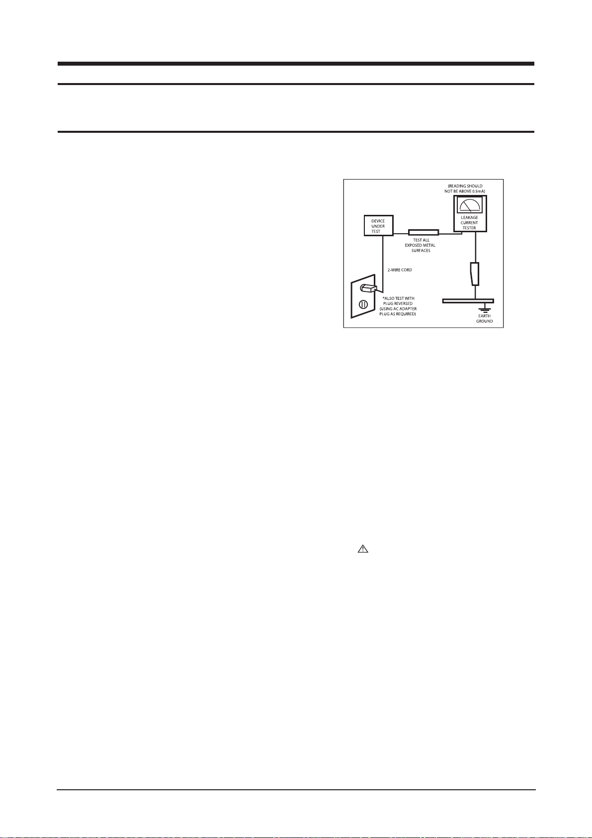
3. Leakage Current Hot Check (Figure 1-1):
WARNING : Do not use an isolation
transformer during this test.
Use a leakage current tester or a metering system that
complies with American National Standards Institute
(ANSI C101.1, Leakage Current for Appliances), and
Underwriters Laboratories (UL Publication UL1410,
59.7).
Figure 1-1. Leakage Current Test Circuit
4. With the unit completely reassembled, plug the AC line
cord directly into a 120V AC outlet. With the unit’s AC
switch first in the ON position and then OFF, measure
the current between a known earth ground (metal water
pipe, conduit, etc.) and all exposed metal parts,
including: metal cabinets, screwheads and control shafts.
The current measured should not exceed 0.5 milliamp.
Reverse the power-plug prongs in the AC outlet and
repeat the test.
1-1-4 Product Safety Notices
Some electrical and mechanical parts have special safetyrelated characteristics which are often not evident from visual
inspection. The protection they give may not be obtained by
replacing them with components rated for higher voltage,
wattage, etc. Parts that have special safety characteristics are
identified by on schematics and parts lists. A substitute
replacement that does not have the same safety characteristics
as the recommended replacement part might create shock, fire
and/or other hazards. Product safety is under review
continuously and new instructions are issued whenever
appropriate.
1 Precautions
Follow these safety, servicing and ESD precautions to prevent damage and to protect against potential hazards such as electrical shock.
1-1 Safety Precautions

1 Precautions
1-2
1-2-1 General Ser vicing
Precautions
1. Always unplug the unit’s AC power cord from the AC
power source and disconnect the DC Power Jack before
attempting to:
(a) remove or reinstall any component or assembly, (b)
disconnect PCB plugs or connectors, (c) connect a test
component in parallel with an electrolytic capacitor.
2. Some components are raised above the printed circuit
board for safety. An insulation tube or tape is sometimes
used. The internal wiring is sometimes clamped to
prevent contact with thermally hot components. Reinstall
all such elements to their original position.
3. After servicing, always check that the screws,
components and wiring have been correctly reinstalled.
Make sure that the area around the serviced part has not
been damaged.
1. Immediately before handling any semiconductor
components or assemblies, drain the electrostatic charge
from your body by touching a known earth ground.
Alternatively, wear a discharging wrist-strap device. To
avoid a shock hazard, be sure to remove the wrist strap
before applying power to the monitor.
2. After removing an ESD-equipped assembly, place it on a
conductive surface such as aluminum foil to prevent
accumulation of an electrostatic charge.
3. Do not use freon-propelled chemicals. These can
generate electrical charges sufficient to damage ESDs.
4. Use only a grounded-tip soldering iron to solder or
desolder ESDs.
5. Use only an anti-static solder removal device. Some
solder removal devices not classified as “anti-static” can
generate electrical charges sufficient to damage ESDs.
4. Check the insulation between the blades of the AC plug
and accessible conductive parts (examples: metal panels,
input terminals and earphone jacks).
5. Insulation Checking Procedure: Disconnect the power
cord from the AC source and turn the power switch ON.
Connect an insulation resistance meter (500 V) to the
blades of the AC plug.
The insulation resistance between each blade of the AC
plug and accessible conductive parts (see above) should
be greater than 1 megohm.
6. Always connect a test instrument’s ground lead to the
instrument chassis ground before connecting the positive
lead; always remove the instrument’s ground lead last.
6. Do not remove a replacement ESD from its protective
package until you are ready to install it. Most
replacement ESDs are packaged with leads that are
electrically shorted together by conductive foam,
aluminum foil or other conductive materials.
7. Immediately before removing the protective material
from the leads of a replacement ESD, touch the
protective material to the chassis or circuit assembly into
which the device will be installed.
Caution:Be sure no power is applied to the
chassis or circuit and observe all
other safety precautions.
8. Minimize body motions when handling unpackaged
replacement ESDs. Motions such as brushing clothes
together, or lifting your foot from a carpeted floor can
generate enough static electricity to damage an ESD.
1-3
Electrostatically Sensitive Devices (ESD) Precautions
Some semiconductor (solid state) devices can be easily damaged by static electricity. Such components are commonly called
Electrostatically Sensitive Devices (ESD). Examples of typical ESD are integrated circuits and some field-effect transistors. The
following techniques will reduce the incidence of component damage caused by static electricity.
1-2 Ser vicing Precautions
WARNING: An electrolytic capacitor installed with the wrong polarity might explode.
Caution: Before servicing units covered by this service manual, read and follow the Safety Precautions section
of this manual.
Note: If unforeseen circumstances create conflict between the following servicing precautions and any of the safety
precautions, always follow the safety precautions.

1 Precautions
1-3
1-4 Installation Precautions
1. For safety reasons, more than two people are
required for carrying the product.
2. Keep the power cord away from any heat emitting
devices, as a melted covering may cause fire or
electric shock.
3. Do not place the product in areas with poor
ventilation such as a bookshelf or closet. The
increased internal temperature may cause fire.
4. Bend the external antenna cable when connecting
it to the product. This is a measure to protect it
from being exposed to moisture. Otherwise, it
may cause a fire or electric shock.
5. Make sure to turn the power off and unplug the
power cord from the outlet before repositioning
the product. Also check the antenna cable or the
external connectors if they are fully unplugged.
Damage to the cord may cause fire or electric
shock.
6. Keep the antenna far away from any high-voltage
cables and install it firmly. Contact with the highvoltage
cable or the antenna falling over may
cause fire or electric shock.
7. When installing the product, leave enough space
(10cm) between the product and the wall for
ventilation purposes.
A rise in temperature within the product may cause fire.

1 Precautions
1-4
Memo

2 Product Specifications
2-1
2 Product Specifications
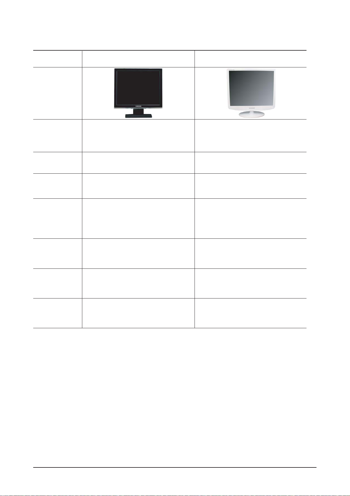
2-1 Fashion Feature
-. Minimalism Design Something New
-. Boltless Model (Clean Cut & Soft Surface)
-. New Ball Hinge
-. Color Variation. White, Black
2-2 LS17PEA Specifications
LCD Panel TFT-LCD panel, RGB vertical stripe, normally black transmissive,
17-Inch viewable, 0.264 (H) x 0.264 (V) mm pixel pitch
Scanning Frequency Horizontal : 31 kHz ~ 81 kHz (Automatic)
Vertical : 56 Hz ~ 75 Hz (UXGA : 60 Hz)
Display Colors 16.7 Million colors
Maximum Resolution Horizontal : 1280 Pixels
Vertical : 1024 Pixels
Input Signal Analog
Input Sync Signal Seperate H/V sync, Composite H/V, Sync-on-Green, Automatic synchroniza
tion whitout external swith of sync type
Level : TTL level
Maximum Pixel Clock rate 135 MHz
Active Display
Horizontal/Vertical 337(H) x 270(W) mm
AC power voltage & Frequency
AC 90 ~ 264 Volts, 60/50 Hz
Power Consumption 34W (Max)
Dimensions
Set (W x D x H) 376.0 x 177.0 x 380.0 mm
Weight (Set/Package) 3.2kg / 4.3kg
Environmental Considerations
Operating Temperature : 0˚F ~ 122˚F (0℃ ~ 50℃)
Operating Humidity : 20% ~ 90%
Storage temperature : -4˚F ~ 149˚F (-20℃ ~ 65℃)
Storage Humidity : 5% ~ 90%
- Designs and specifications are subject to change without prior notice.
Description
Item
2 Product Specifications
2-2
2-3 LS19PEB Specifications
LCD Panel TFT-LCD panel, RGB vertical stripe, normally black transmissive,
19-Inch viewable, 0.294 (H) x 0.294 (V) mm pixel pitch
Scanning Frequency Horizontal : 31 kHz ~ 81 kHz (Automatic)
Vertical : 56 Hz ~ 75 Hz (UXGA : 60 Hz)
Display Colors 16.7 Million colors
Maximum Resolution Horizontal : 1280 Pixels
Vertical : 1024 Pixels
Input Signal Analog / Digital
Input Sync Signal Seperate H/V sync, Composite H/V, Sync-on-Green, Automatic synchroniza
tion whitout external swith of sync type
Level : TTL level
Maximum Pixel Clock rate 135 MHz
Active Display
Horizontal/Vertical 376.3(H) x 301.05(W) mm
AC power voltage & Frequency
AC 90 ~ 264 Volts, 60/50 Hz
Power Consumption 38W (Max)
Dimensions
Set (W x D x H) 418.0 x 199.0 x 418.0 mm
Weight (Set/Package) 4.0kg / 5.3kg
Environmental Considerations
Operating Temperature : 0˚F ~ 122˚F (0℃ ~ 50℃)
Operating Humidity : 20% ~ 90%
Storage temperature : -4˚F ~ 149˚F (-20℃ ~ 65℃)
Storage Humidity : 5% ~ 90%
- Designs and specifications are subject to change without prior notice.
Description
Item

2 Product Specifications
2-3
2-4 LS19PEA Specifications
LCD Panel TFT-LCD panel, RGB vertical stripe, normally black transmissive,
19-Inch viewable, 0.294 (H) x 0.294 (V) mm pixel pitch
Scanning Frequency Horizontal : 31 kHz ~ 81 kHz (Automatic)
Vertical : 56 Hz ~ 75 Hz (UXGA : 60 Hz)
Display Colors 16.7 Million colors
Maximum Resolution Horizontal : 1280 Pixels
Vertical : 1024 Pixels
Input Signal Analog
Input Sync Signal Seperate H/V sync, Composite H/V, Sync-on-Green, Automatic synchroniza
tion whitout external swith of sync type
Level : TTL level
Maximum Pixel Clock rate 135 MHz
Active Display
Horizontal/Vertical 376.3(H) x 301.05(W) mm
AC power voltage & Frequency
AC 90 ~ 264 Volts, 60/50 Hz
Power Consumption 38W (Max)
Dimensions
Set (W x D x H) 418.0 x 199.0 x 418.0 mm
Weight (Set/Package) 4.0kg / 5.3kg
Environmental Considerations
Operating Temperature : 0˚F ~ 122˚F (0℃ ~ 50℃)
Operating Humidity : 20% ~ 90%
Storage temperature : -4˚F ~ 149˚F (-20℃ ~ 65℃)
Storage Humidity : 5% ~ 90%
- Designs and specifications are subject to change without prior notice.
Description
Item
2 Product Specifications
2-4
2-5 Spec Comparison
BI17BS / 19BS
Model
Design
Frequency
Horizontal
Vertical
Display Color
30 ~ 81 kHz
60 ~ 75 Hz
16,2M colors
30 ~ 81 kHz
60 ~ 75 Hz
16,7M colors
PC Resolution
Maximum mode
Input Signal
Sync Signal
Video Signal
Power
Consumption
Normal
Power Saving
8ms
None
Support
17" : 5ms
19" : 5ms
None
Support (Deleted Magic Zone)
Response Time
Anion Option
Magic Color
34W / 38W
< 1W
34W / 38W
< 1W
H/V Separate, TTL, P. or N.
0.7 Vp-p @ 75ohm
H/V Separate, TTL, P. or N.
0.7 Vp-p @ 75ohm
1280 x 1024 / 60 Hz 1280 x 1024 / 60 Hz
LS17PEA / LS19PEA / LS19PEB
2 Product Specifications
2-5
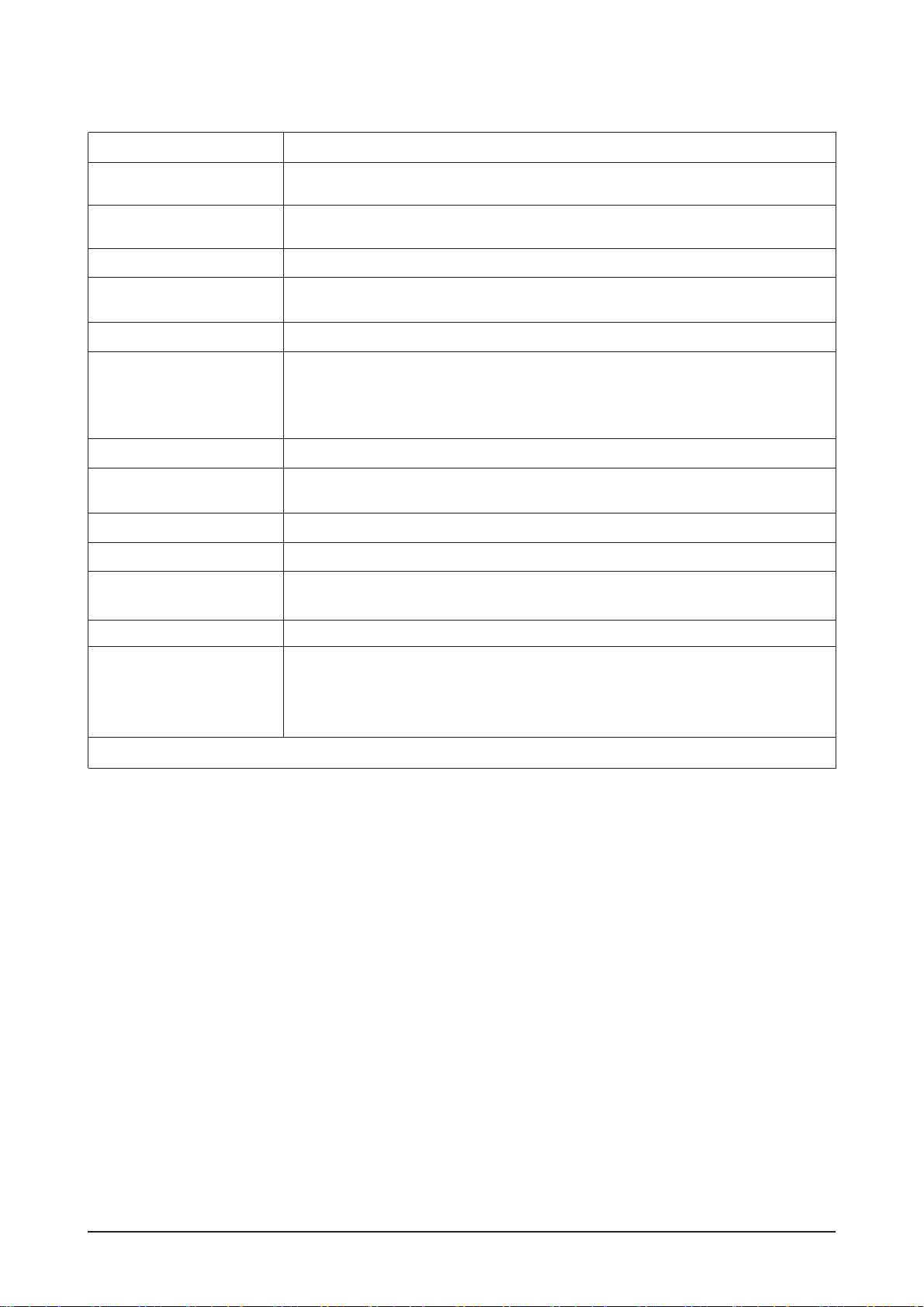
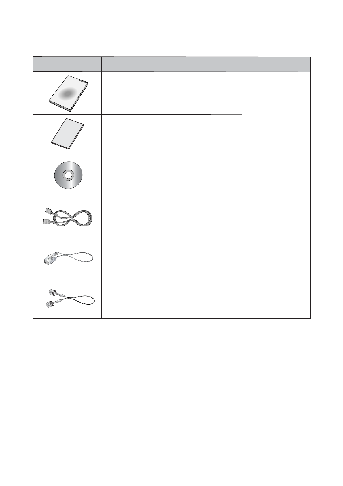
Item Item Name CODE.NO Remark
Quick Setup Guide
BN68-01002C
AA68-00371C
LS17PEA, LS19PEB:
BN59-00585A
LS19PEA:
BN59-00585L
BN39-00244B
3903-000042
BN39-00246F Sold separately
Warranty Card
(Not available in all
locations)
User's Guide,
Monitor Driver,
Natural Color software,
MagicTune™ software
D-Sub(15 Pin)
Cable
Power Cord
DVI Cable
2-6 Option Specification

Memo
2 Product Specifications
2-6
3 Alignments and Adjustments
3-1
3-1 Required Equipment
The following equipment is necessary for adjusting the monitor:
- Computer with Windows 95, Windows 98, or Windows NT.
- MTI-2031 DDC MANAGER JIG
3-2 Automatic Color Adjustment
To input video, use 16 gray or any pattern using black and white.
1. Select english for OSD language.
2. Press the " (Enter/Source)" key for 5 seconds.
3-3 DDC EDID Data Input
1. Input DDC EDID data when replacing AD PCB.
2. Receive/Download the proper DDC file for the model from HQ quality control department.
Install the below jig (Figure 1) and enter the data.
3-4 OSD Adjustment When Replacing Panel
1. Adjust brightness and contrast to 0. Then, press the (Enter/Source) key for 5 seconds.
Service function OSD will appear on screen.
2. Press the + key to place the cursor on the panel. Press the menu key for 5 seconds.
3-5 OSD Adjustment When Replacing Lamp Only
1. Adjust brightness and contrast to 0. Then, press the exit key for 5 seconds.
Service function OSD will appear on the screen.
2. Press the + key. Select upper lamp and press the menu key for 5 seconds.
Then, select lower lamp and press the menu key for 5 seconds.
-Note : Please be sure to read the following instructions for details on service function.
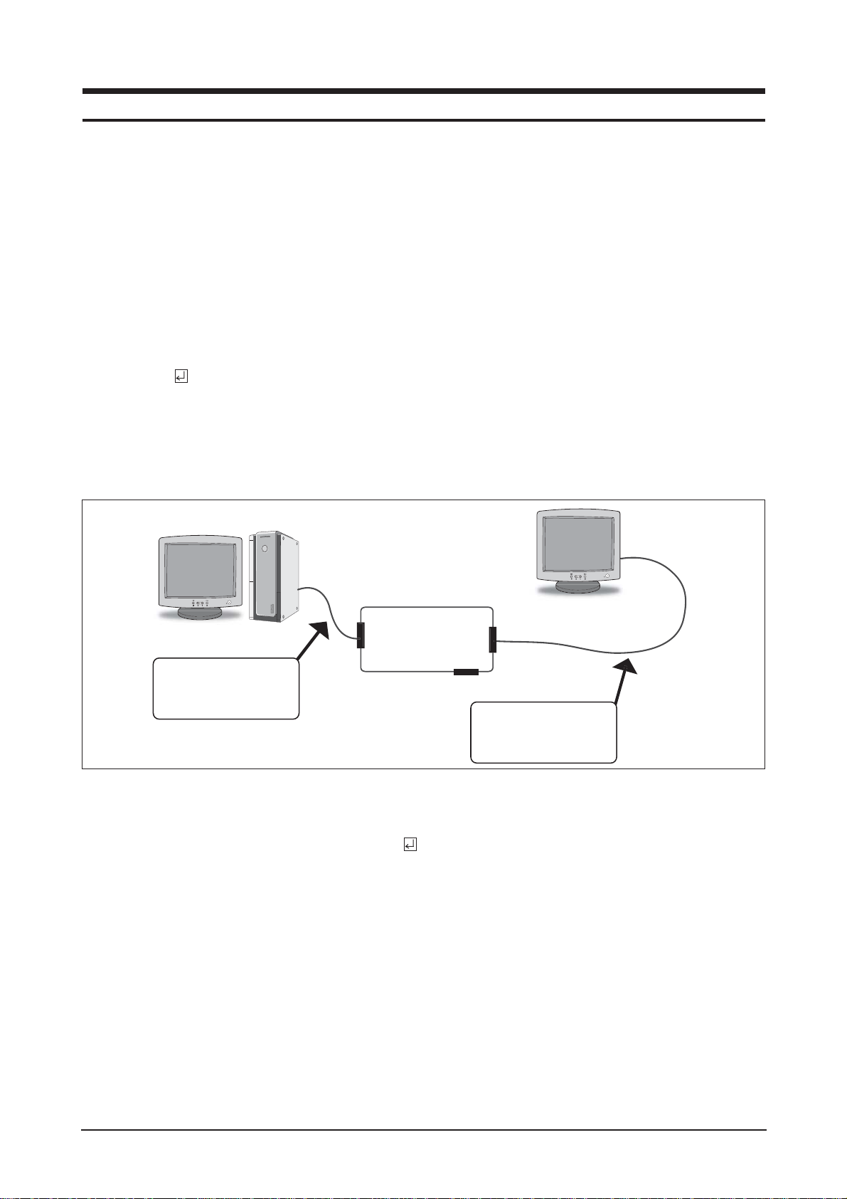
3 Alignments and Adjustments
This section of the service manual explains how to use the DDC MANAGER JIG.
This function is needed for AD board change and program memory (IC110) change.
031
Figure 1.
TI-2
DDC Manager
Parallel Connector
(25P Cable)
Connect Monitor
(Signal Cable)
3 Alignments and Adjustments
3-2
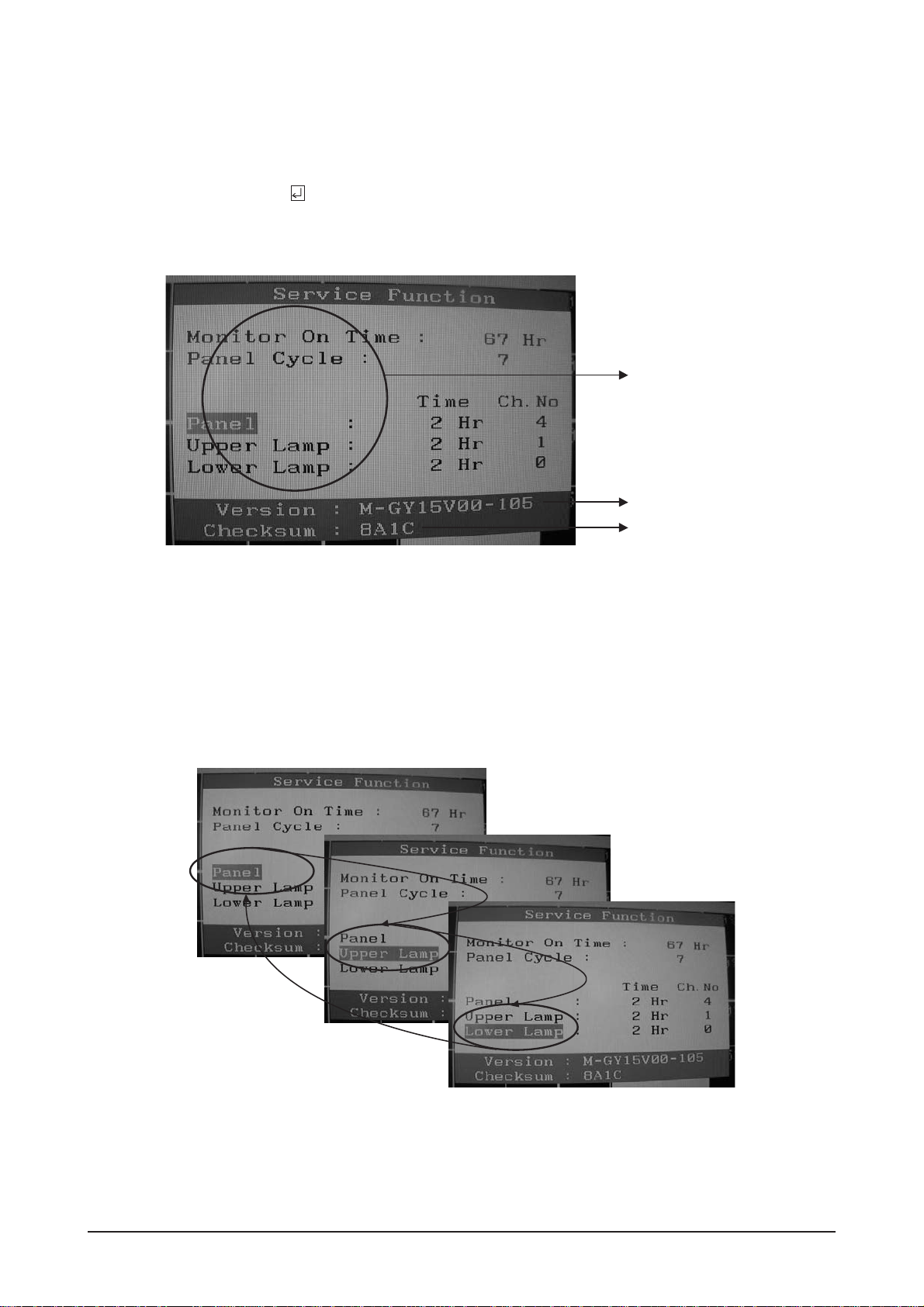
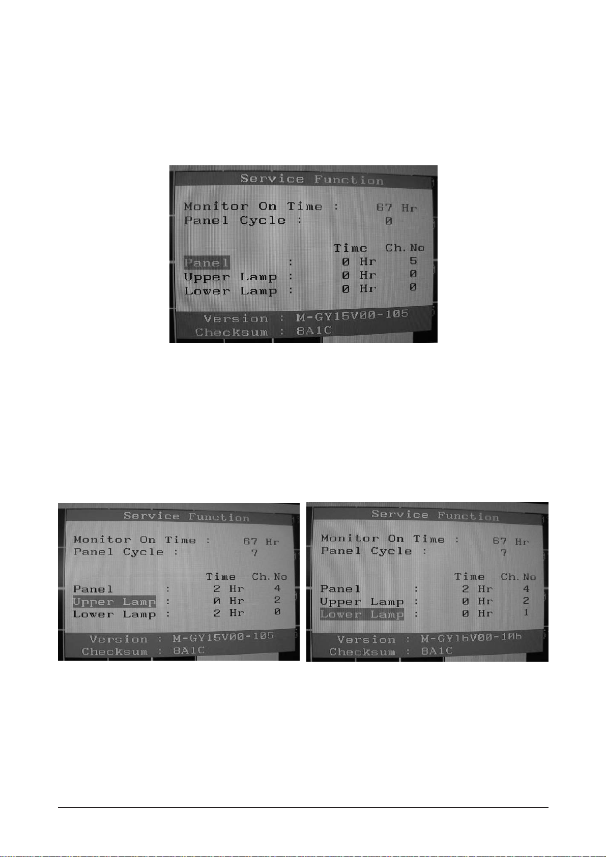
3-6 Ser vice Function Spec.
3-6-1 How to Display Service Function OSD
1. The value for brightness and contrast should be changed to zero.
2. Within 5 seconds, press the (Enter/Source) key.
3. Service function OSD will be displayed.
-If you want to disable the service function OSD, you will have to power off.
Figure 2. The example of service function OSD
Figure 3.
Panel Information
Software Version
Checksum
The service function OSD is based on a grid of 29 columns x 12 rows.
The service function OSD consists of panel information, software version and MICOM checksum.
3-6-2 How to Control Ser vice Function OSD
1. With the panel selected on OSD, whenever you press the right key, the base color will change to blue from
"Panel" to "Upper Lamp", "Lower Lamp".
3 Alignments and Adjustments
3-3
Figure 4.
3-6-3 How to Control Ser vice Function OSD
-After changing the panel or lamp, you must reset service function OSD.
-The case of panel change
After changing the panel, press the menu key within 5 seconds,.
Then, panel Ch. No increases one step and the panel time information is reset to zero.
Simultaneously, other information is reset to zero (Upper/Lower lamp, Panel cycle).
Figure 5, 6.
3-6-4 How to Control Ser vice Function OSD
-In the case of Upper Lamp or Lower Lamp change
After changing the Upper Lamp or Lower Lamp,
1. Select the Upper Lamp or Lower Lamp
2. Press the Menu key within an 5 seconds.
Then, Ch. No and time will be reset to zero (selected item only).
3 Alignments and Adjustments
3-4
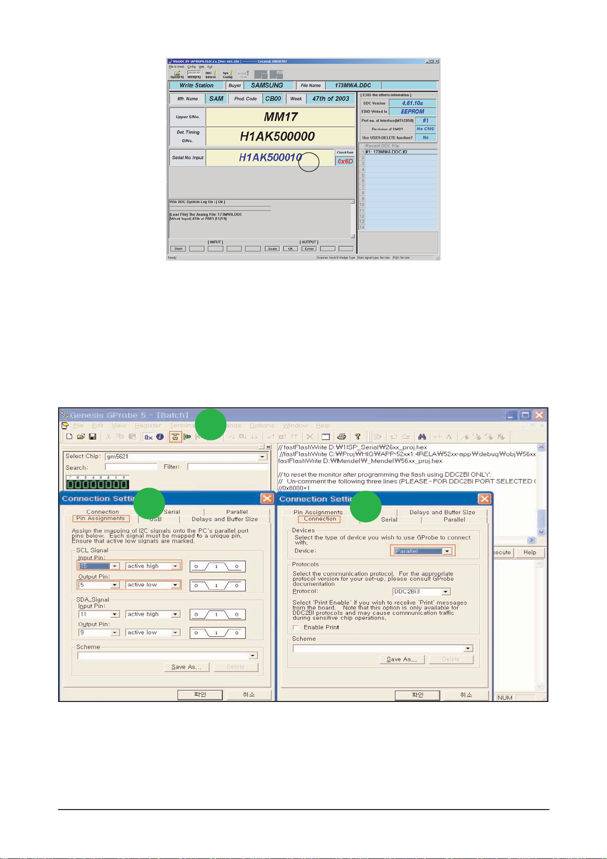
3-7 How to execute DDC
3-7-1 After exchange the Main PBA, confirm below items
1. Open file.
2. Select Port #1.
3. Select DDC file.
4. Click, "Next" Button
1. PC color status check (Auto Color)
2. EDID Input (Analog and Digital)
3. Check the MCU Code
(After change MCU Code, Do Auto color )
4. Factory Reset
1) Run DDC Manager MTI-2050.
2) Select a DDC file name.
Progtam : WinDDC BY SAMSUNG ELEC.Co. [Ver:4.65.12V] --- Modify : 20050425
DDC : 732N.ddc or 932B.ddc
3) Insert into DDC Manager Port 1 (analog) and make the DDC input as for the old dual model.
4) Insert into DDC Manager Port 2 (Digital) and make the DDC input.
1
2
3
4
3 Alignments and Adjustments
3-5
5
5. Type in the monitor serial number and press Enter.
*Repeat this step 2 to 5 times in digital inputs after the analog input.
3-8 How to execute MCU Code
1. Click Config Setting
2. Change SCL Signal at Pin Assignments
3. Set Device to Parallel
3-8-1 Program Setting - Config Setting
1
2
3

3 Alignments and Adjustments
3-6
4. Change the Code's Path to saved Path at your PC.
5. Save the Batch file.
6. Write Batch command
"batch batch file name.txt"
7. Click "Execute" Button
8. If command is "Successful" , Hard Power On/Off until LED is Off
- If command is "Error",
1. Hard Power Off
2. Write Command "forcesa"
3. Click "Execute" Button
4. Repeat again 7 to 9.
5
4
6
7
8
3-8-2 Change Batch File Path and DownLoad Code

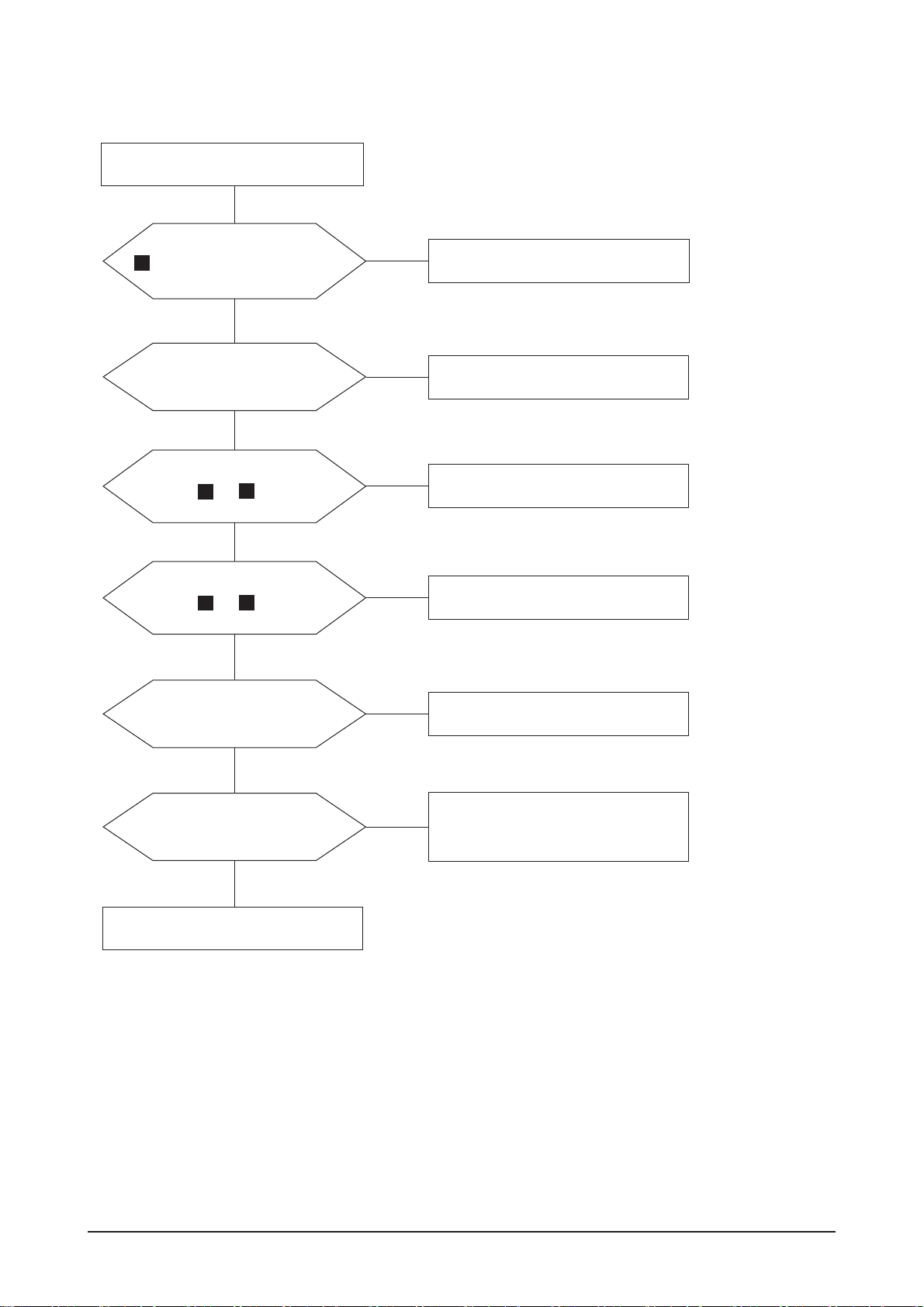
4 Troubleshooting
4-1
4 Troubleshooting
4-1 No Power (17", 19")
When Pin 4 of CN600 is 0V
does proper DC 13V, 5V
appear at Pin 5 and 6, 7 of
CN600 separately?
Change IP Board.
Check Function Ass'y.
Yes
Yes
No
When Pin 1 of IC600 is DC 5V
does proper DC 3.3V appear at
Pin 3 of IC600?
Check IC600 and related circuit.
Yes
No
When Pin3 of IC602 is DC 3.3V
does proper DC1.8V appear at
Pin2 of IC602?
Check IC602 and related circuit.
No
* All locations of this page includes Main PBA.
Notes: 1. Before troubleshooting, setup the PC 's display as below.
• Resolution: 1024 x 768
• H-frequency: 61 kHz
• V-frequency: 75 Hz
2. If no picture appears, make sure the power cord is correctly connected.
3. Check the following circuits.
• No raster appears: Function PBA, Main PBA, I/P PBA
• 5V develop but no screen: Main PBA
• 5V does not develop: I/P PBA
4. If you push and hold the " (Enter/Source)" button for more than 5 seconds, the monitor
automatically returns to the factory preset.
4 Troubleshooting
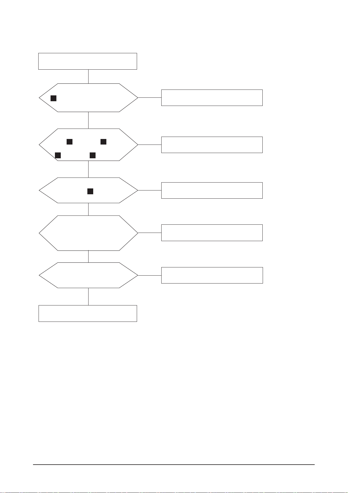
4-2
X400 oscillate properly?
4-2 No Video (ANALOG 17", 19")
1
Replace or check related circuit.
Check signal cable connection and
power.
Yes
No
Is there R, G, B input at
R101, R100 and R103?
Check input part.
Yes
No
Is there Hsync, Vsync waveform
at Pin 100, 1 of IC 400?
Check IC400 and related circuit.
No
2
3
Yes
Is there Hsync, Vsync waveform
at Pin 43, 44 of IC 200?
Check IC200 and related circuit.
No
Yes
Does the output signal appear
at Pin 17~20, 22~27 of CN400?
Check CN400 and related circuit.
No
Yes
There are DC 5V at Pin 1,
2 and 3 of CN400?
Check PANEL_EN SIGNAL at R222
is High(On:High) and BL_EN signal
at R603(ON:Low) is Low
No
Yes
Replace LCD Panel.
2
3
* All locations of this page includes Main PBA.
4 Troubleshooting
4-3
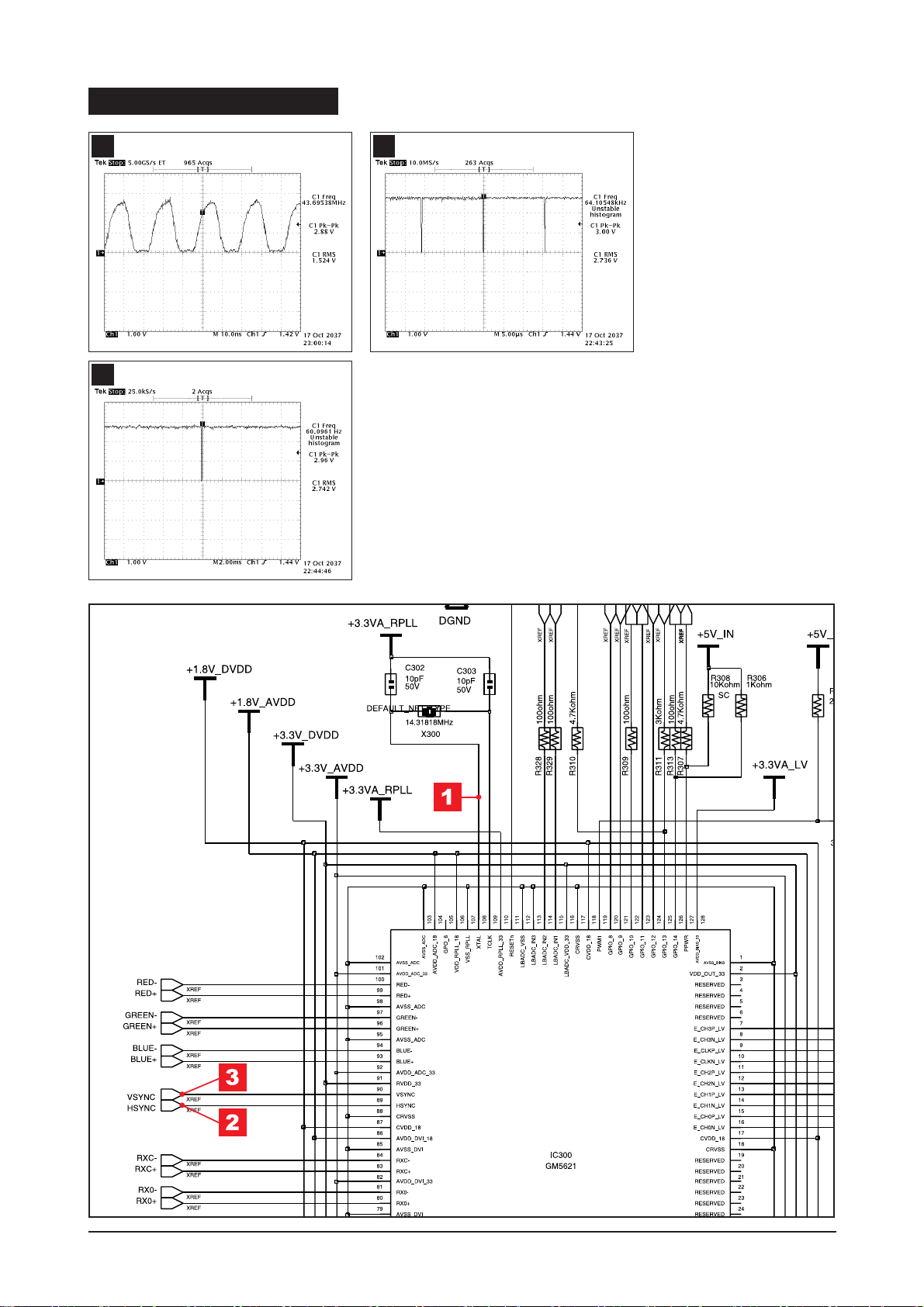
1
WAVEFORMS
2
3
4 Troubleshooting
4-4
X400 oscillate properly?
4-3 No Video (DIGITAL LS19PEB)
1
Replace or check related circuit.
Check signal cable connection and
power.
Yes
No
Is there R, G, B input at
R100, R101, R102, R103,
R104 and R105?
Check input part.
Yes
No
Is there waveform
at R106, R107?
Check input part.
No
Yes
Does the output signal
appear at Pin 17~20, 22~27
of CN400?
Check IC400 and related circuit.
No
Yes
There are DC 5V at Pin 28,
29 and 30 of CN400?
Check the PANEL_EN signal at R222
and BL_EN signal at R603.
No
Yes
Replace LCD Panel.
7
6 6
4 5
* All locations of this page includes Main PBA.
 Loading...