

Page 1
Series 6495
Industrial Controller TROVIS 6495-2
Electronics from SAMSON
Mounting and
Operating Instructions
EB 6495-2 EN
®
Firmware version 1.11
Edition December 2009
Page 2

Definitions of the signal words used in these instructions
!
DANGER!
DANGER indicates a hazardous situation
which, if not avoided, will result in death or
NOTICE
NOTICE indicates a property damage mes
sage.
serious injury.
-
2 EB 6495-2 EN
Note: Supplementary explanations, informa
tion and tips
-
Page 3

Contents
Contents Page
1 Important safety instructions . . . . . . . . . . . . . . . . . . . . . . 5
2 Device version . . . . . . . . . . . . . . . . . . . . . . . . . . . . . 6
2.1 Article code . . . . . . . . . . . . . . . . . . . . . . . . . . . . . . 6
2.2 Accessories. . . . . . . . . . . . . . . . . . . . . . . . . . . . . . . 6
3 Installation . . . . . . . . . . . . . . . . . . . . . . . . . . . . . . . 7
4 Electrical connection . . . . . . . . . . . . . . . . . . . . . . . . . . 8
5 Operation . . . . . . . . . . . . . . . . . . . . . . . . . . . . . . 12
5.1 Operation structure . . . . . . . . . . . . . . . . . . . . . . . . . . 12
5.2 Display and operator controls . . . . . . . . . . . . . . . . . . . . . 13
6 Operating level . . . . . . . . . . . . . . . . . . . . . . . . . . . . 15
6.1 Changing the set point. . . . . . . . . . . . . . . . . . . . . . . . . 16
6.2 Switching over to manual mode and changing the output . . . . . . . . . 16
6.3 Opening/closing cascade . . . . . . . . . . . . . . . . . . . . . . . 17
7 Info menu. . . . . . . . . . . . . . . . . . . . . . . . . . . . . . . 19
8 Operating menu . . . . . . . . . . . . . . . . . . . . . . . . . . . 23
8.1 Entering the operating menu . . . . . . . . . . . . . . . . . . . . . . 23
8.2 Changing the control parameters. . . . . . . . . . . . . . . . . . . . 23
8.3 Switching over internal/external set point. . . . . . . . . . . . . . . . 25
8.4 Switching over between internal set points and changing them . . . . . 25
9 Configuration menu. . . . . . . . . . . . . . . . . . . . . . . . . . 29
9.1 Entering the configuration level . . . . . . . . . . . . . . . . . . . . 29
9.2 Configuring the controller . . . . . . . . . . . . . . . . . . . . . . . 30
9.2.1 Setting configuration items. . . . . . . . . . . . . . . . . . . . . . . 30
9.2.2 Configuration example . . . . . . . . . . . . . . . . . . . . . . . . 31
9.3 Adapting the display . . . . . . . . . . . . . . . . . . . . . . . . . 33
9.3.1 Changing the controller display . . . . . . . . . . . . . . . . . . . . 33
9.3.2 Setting up additional display. . . . . . . . . . . . . . . . . . . . . . 35
9.3.3 Switching Controller [1] and Controller [2] displays . . . . . . . . . . . 38
10 Locking the controller . . . . . . . . . . . . . . . . . . . . . . . . . 41
10.1 Locking the operating level. . . . . . . . . . . . . . . . . . . . . . . 41
10.2 Locking all keys over a digital input . . . . . . . . . . . . . . . . . . 42
10.3 Activating key number operation . . . . . . . . . . . . . . . . . . . 43
11 User calibration. . . . . . . . . . . . . . . . . . . . . . . . . . . . 45
11.1 Calibrating analog inputs . . . . . . . . . . . . . . . . . . . . . . . 45
EB 6495-2 EN 3
Page 4

Contents
11.2 Calibrating analog outputs. . . . . . . . . . . . . . . . . . . . . . . 45
12 Fault alarms . . . . . . . . . . . . . . . . . . . . . . . . . . . . . 46
13 Interfaces . . . . . . . . . . . . . . . . . . . . . . . . . . . . . . . 48
13.1 Infrared interface . . . . . . . . . . . . . . . . . . . . . . . . . . . 49
13.2 Optional interface boards . . . . . . . . . . . . . . . . . . . . . . . 50
13.2.1 RS-232/USB interface board . . . . . . . . . . . . . . . . . . . . . 50
13.2.2 RS-485/USB interface board . . . . . . . . . . . . . . . . . . . . . 51
13.3 SAMSON memory pen . . . . . . . . . . . . . . . . . . . . . . . . 53
14 Setting and operation with TROVIS-VIEW software . . . . . . . . . . 55
14.1 General. . . . . . . . . . . . . . . . . . . . . . . . . . . . . . . . 55
14.1.1 System requirements. . . . . . . . . . . . . . . . . . . . . . . . . . 55
14.2 Installing TROVIS-VIEW software. . . . . . . . . . . . . . . . . . . . 56
14.3 Starting TROVIS-VIEW and performing settings . . . . . . . . . . . . . 57
14.3.1 Configuring the controller . . . . . . . . . . . . . . . . . . . . . . . 60
14.3.2 Reading information. . . . . . . . . . . . . . . . . . . . . . . . . . 62
14.4 Operational data graphs (Trend Viewer) . . . . . . . . . . . . . . . . 64
14.5 Data transmission . . . . . . . . . . . . . . . . . . . . . . . . . . . 66
14.5.1 Setting up communication port . . . . . . . . . . . . . . . . . . . . . 66
14.5.2 Online operation (direct data transmission) . . . . . . . . . . . . . . . 67
14.5.3 Offline operation (indirect data transmission) . . . . . . . . . . . . . . 67
14.5.4 Data transmission between TROVIS-VIEW and memory pen. . . . . . . 68
15 Appendix. . . . . . . . . . . . . . . . . . . . . . . . . . . . . . . 69
15.1 Technical data . . . . . . . . . . . . . . . . . . . . . . . . . . . . 69
15.2 Configuration list . . . . . . . . . . . . . . . . . . . . . . . . . . . 73
15.3 Abbreviations used. . . . . . . . . . . . . . . . . . . . . . . . . . 145
15.4 Block diagrams . . . . . . . . . . . . . . . . . . . . . . . . . . . 145
Index . . . . . . . . . . . . . . . . . . . . . . . . . . . . . . . . 152
4 EB 6495-2 EN
Page 5

1 Important safety instructions
Important safety instructions
For your own safety, follow these instructions concerning the mounting, start-up and opera
tion of the industrial controller:
The industrial controller may only be mounted, started up or operated by trained and
4
experienced personnel familiar with the product.
According to these Mounting and Operating Instructions, trained personnel refers to
individuals who are able to judge the work they are assigned to and recognize possi
ble dangers due to their specialized training, their knowledge and experience as well
as their knowledge of the relevant standards.
The controller is intended for use in low-voltage installations.
4
For wiring and maintenance, you are required to observe the relevant safety regula
tions.
To avoid damage to any equipment, the following also applies:
Proper shipping and appropriate storage are assumed.
4
-
-
-
EB 6495-2 EN 5
Page 6

Device version
2 Device version
2.1 Article code
Industrial Controller TROVIS 6495-2 x
Supply voltage
85 to 264 V AC
24 V AC/DC
1
2
2.2 Accessories
Accessories Order no.
TROVIS-VIEW Configuration
and Operator Interface.......... 6661-1033
Infrared adapter (RS-232)...... 8864-0900
Bracket for infrared adapter... 1400-9769
USB 1.1 serial adapter........... 8812-2001
RS-232/USB interface board.. 1400-9917
RS-485/USB interface board.. 1400-9918
USB cable (2 m) with type A
and 5-pin mini-B connectors... 8801-7301
Connecting cable
RJ 12/D-sub 9-pin (RS-232)... 1400-7699
Memory pen (RS-232)........... 1400-9753
Modular adapter
RJ 12/D-sub 9-pin................. 1400-7698
6 EB 6495-2 EN
Page 7
Installation
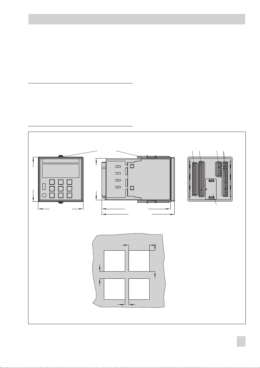
3 Installation
The TROVIS 6495-2 Industrial Controller is
designed for panel mounting. Its front case
has the dimensions 96 x 96 mm.
NOTICE
When installing several TROVIS 6495-2 In
dustrial Controllers, the minimum distance
between each controller as shown in Fig. 1
must be kept!
Mounting
clips
96 (3.78")
96 (3.78")
91.2 (3.59")
1. Prepare a panel cut-out with the dimen
sions 92
+0.8
x 92
+0.8
2. Push the industrial controller into the
panel cut-out from the front.
3. Insert the two mounting clips in the
notches on the top and bottom.
4. Turn the threaded rods in the direction
-
of the control panel using a screw
driver, clamping the case against the
control panel.
Terminal strips
12 34
150 (5.90")
156 (6.14")
Slot for interface board
-
mm.
-
Panel cut-out and
minimum distances
when installing several
controllers
Fig. 1 · Installation
>30
Panel
cut-out
>15
92
(3.62"
+0.8
+0.3
)
)
+0.3
+0.8
92
(3.62"
EB 6495-2 EN 7
Page 8

Electrical connection
4 Electrical connection
!
Risk of electric shock!
When installing electric cables, you are re
quired to observe the regulations governing
electrical power plant installation in the
country where the controller is to be in
stalled.
Installation notes
Install the power supply lines and the sig
•
nal lines separately! Do not install them
parallel to each other! To improve noise
immunity, observe a minimum distance of
10 cm between the power line and the
measuring input line. The lines for the digital signals (bus lines) as well as the analog signal lines (sensor lines, analog inputs and outputs) must also be routed
using separate cables.
•
To avoid measurement errors or other disturbances, use shielded cables for the analog and binary signal lines and bus
lines. Ground the shield at one end, either
at the controller inlet or at the control cab
inet outlet, using the largest possible
cross-section. Connect the central ground
ing point and the PE grounding conductor
with a cable≥10 mm² using the shortest
route.
•
Inductances in the control cabinet, e.g.
contactor coils, are to be equipped with
suitable interference suppressors (RC ele
ments).
•
Control cabinet elements with high field
strength, e.g. transformers or frequency
converters, are to be shielded with sepa
-
rators providing a good ground connec
tion.
The controller has screw terminals for
1.5 mm² wires (0.5 to 1.5 mm² wire
-
cross-section).
The lines are connected to the terminal strips
1 to 4 as shown in the following connection
diagrams 2a to 2c.
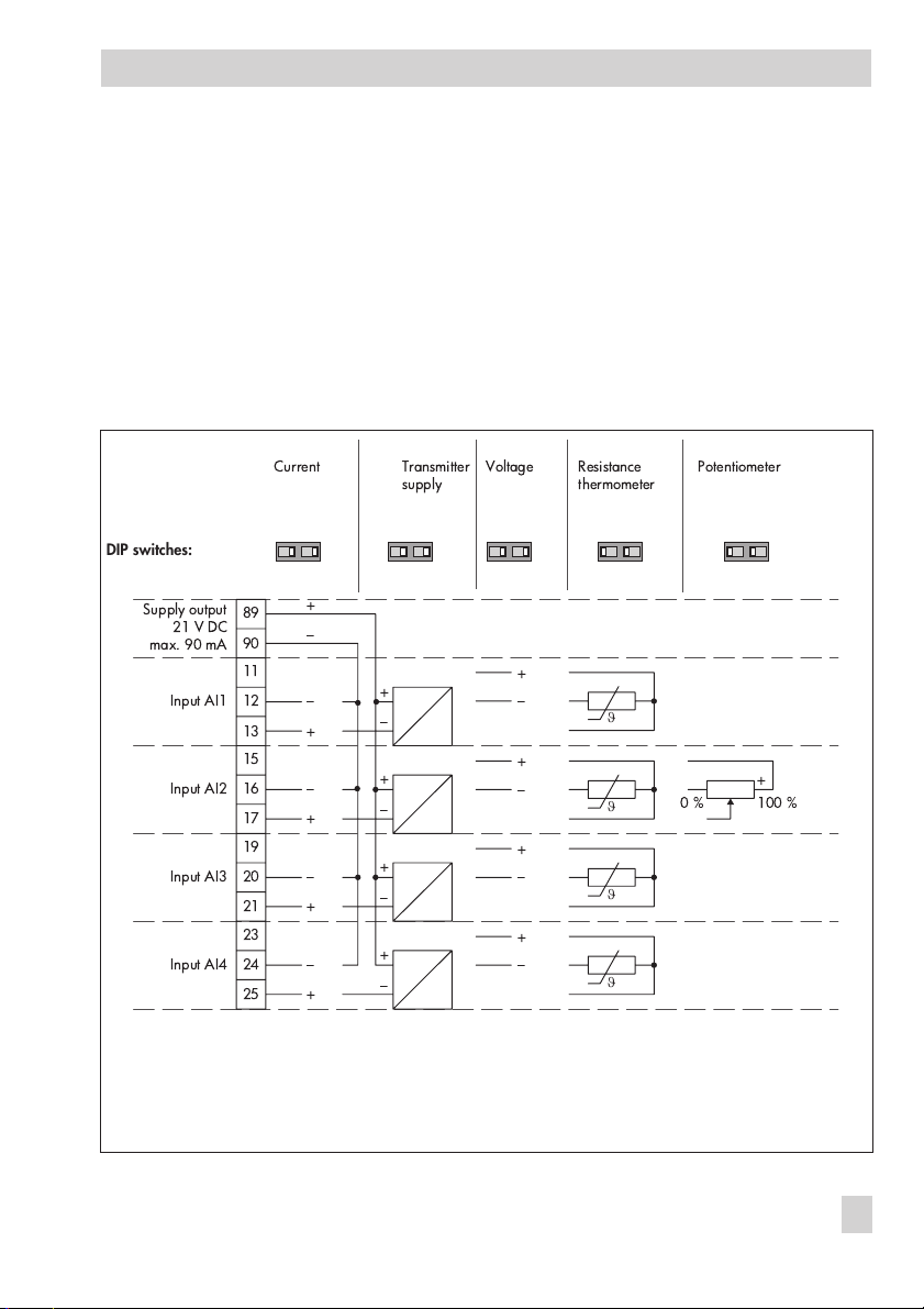
Transmitter supply
The controller has a supply output to power
a maximum of four two-wire transmitters
(21 V DC, 90 mA).
Resistance thermometer
The analog inputs AI1 to AI4 are designed
for the connection of resistance thermometers Pt 100 and Pt 1000 in a three-wire circuit. The resistance of each connection lead
must be the same and not exceed 15Ω.
Lead calibration is not necessary.
Resistance thermometers can also be connected in two-wire circuits. In this case,
connect a jumper between the controller ter
-
minals. Take into account that the lead resis
tance may reach several ohms over long
-
distances, causing the measured value to be
considerably distorted. This measured value
can be balanced out using a correction
value (configuration item
I.1.4/I.2.4/I.3.4/I.4.4 Input signal
increase/decrease, see section 15.2).
-
-
-
-
-
8 EB 6495-2 EN
Page 9
Electrical connection
Potentiometer
The analog input AI2 is designed for the
connection of a potentiometer. Potentiome
ters between 50 and 1200Ωcan be
connected.
A potentiometer is used, for example for po
sition feedback of an electrical actuator or
for input of an external set point.
Terminal strip 1
DIP switches:
(
)
* &
'&
&
"
%
$
&
"
Generally, we recommend performing a
user calibration. To perform a calibration,
use the configuration items A.20.2.13
-
(zero) and A.20.2.14 (end), see section
11.
-
ϑ
ϑ
ϑ
ϑ
!
##
Fig. 2a · Electrical connection
EB 6495-2 EN 9
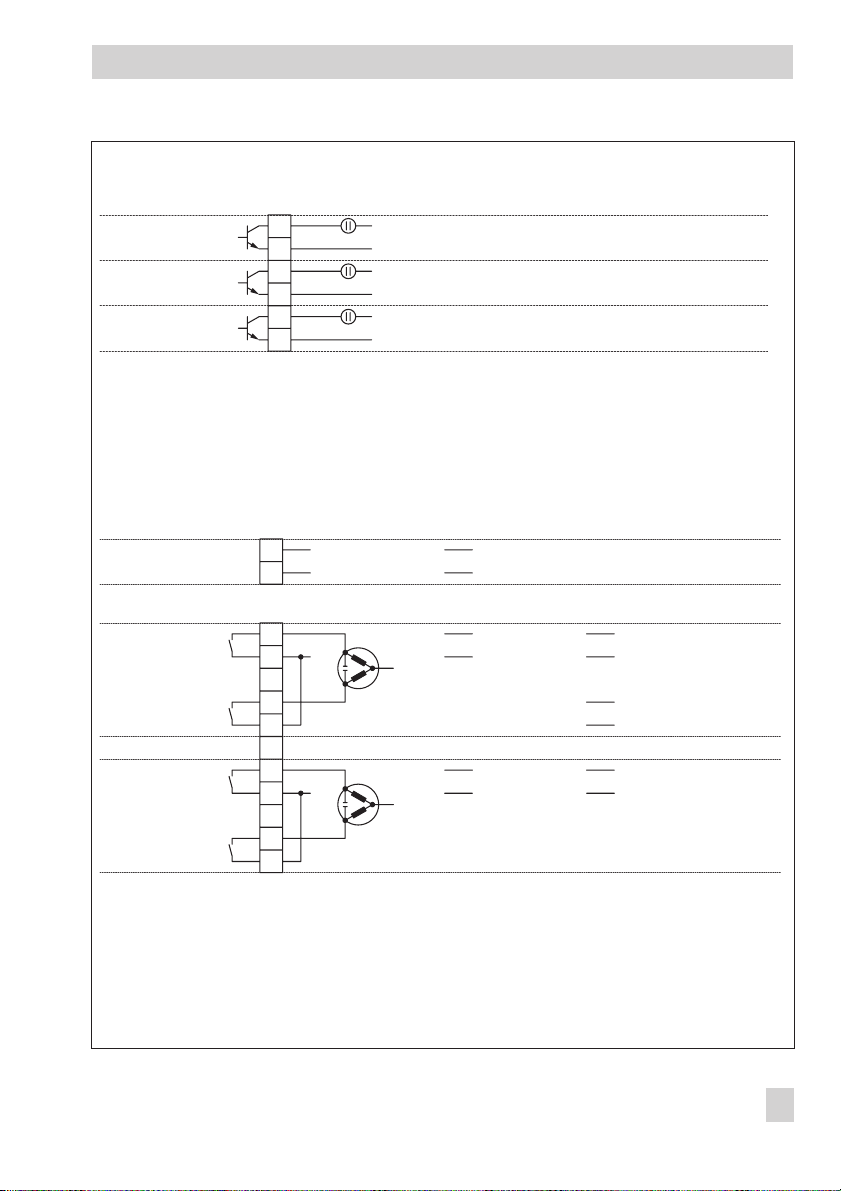
Page 10
Electrical connection
T
C
Terminal strip 2
Supply output
21 V DC
max. 90 mA
Digital input DI1
GND8382
Digital input DI2
Digital input DI3
GND
Digital input DI4
89
90
+
–
31
32Analog output AO1
33
81
35
36Analog output AO2
37
97
98Analog output AO3
99
85
86
87
Current
0/4 to 20 mA
+
–
+
–
+
+
–
+
–
+
–
+
Voltage
0/2 to 10 V
–
+
–
+
–
+
Digital input
with internal supply
Digital input
with external supply
24 V DC
+
–
24 V DC
+
–
RS-485/USB interface (option, see section 13.2.2)
4-wire
AR
RX
BR
BTR
TX RX/TX
ATR
Fig. 2b · Electrical connection
10 EB 6495-2 EN
2-wire
2-Leiter4-Leiter
RS-232 interface (option, see section 13.2.1)
ND
R
16
D
V
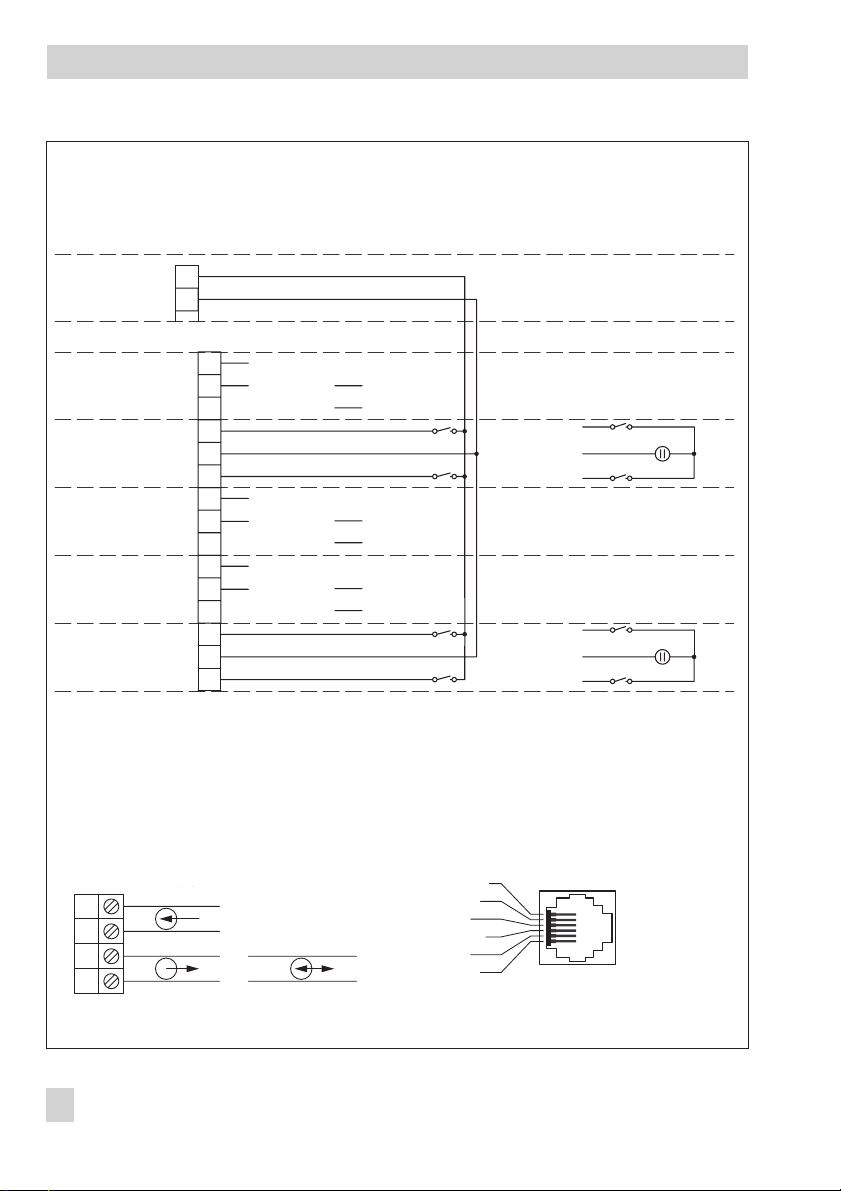
Page 11
Terminal strip 3
Digital output DO5
Digital output DO6
Digital output DO7
Terminal strip 4
Supply
3 to 42 V DC, max. 30 mA
+
61
62
63
64
65
–
+
–
+
–
66
Electrical connection
Supply voltage
Switch output SO1 (+)
Digital output DO1
Switch output SO1 (–)
Digital output DO2
Switch output SO2 (+)
Digital output DO3
Switch output SO2 (–)
Digital output DO4
Fig. 2c · Electrical connection
L
L
85 to 264 V AC 24 V AC/DC (20 to 30 V)
N
N
Three-step output
for motor-driven actuator
42
43
52
53
45
46
55
56
+
L1
–
+
L1 L1
–
On/off output with
pulse-pause modulation
N
N
L+
L–
Digital output:
limit values, alarms, on/off output
+
L1
+
EB 6495-2 EN 11
Page 12
Operation
5 Operation
5.1 Operation structure
The controller has the following operation
levels:
Operating level (Fig. 3):
The controller is in this level while the con
troller is in operation. Key information on
the control process are displayed in this
level.
Info menu:
The info menu consists of several menu items
containing information on the running
process and the firmware version.
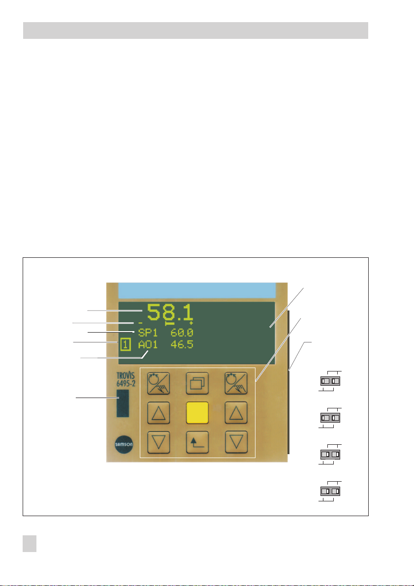
Controlled variable
Error
Reference variable
Controller
Manipulated
variable (output)
Infrared
interface
Fig. 3 · Display and operating controls
-
Operating menu:
The operating menu allows the control pa
rameter and set points to be changed. These
are located in two different menu items.
Configuration menu:
The controller is adapted to its control task
by changing configuration items and pa
rameters.
The configuration level is divided into menus
and submenus. The submenus contain the
individual configuration items and parame
ters.
Display
Key panel with
operator keys
DIP switch
(at the side of the
housing)
mA / V
AI1
Pt 100
Pt 1000
mA / V
AI2
Pt 100
Pt 1000
Potentiometer
Pt 100
Pt 1000
Pt 100
Pt 1000
mA / V
AI3
mA / V
AI4
-
12 EB 6495-2 EN
Page 13

Operation
5.2 Display and operator
controls
Display
The controller is in the operating level while
the controller is in operation.
The display is divided into two sections.
Each section is assigned to one controller.
The default assignment is as follows:
Left display: Controller [1]
4
Right display: Controller [2]
4
The controlled variable (actual value), error,
set point and manipulated variable (output)
are displayed for each controller in the default setting.
Status messages concerning the digital inputs and outputs can be displayed depending on the configuration. For control modes
with just one controller, further signals can
be displayed in five rows in the additional
display.
Infrared interface
Data are transmitted between the controller
and TROVIS-VIEW installed on the computer
over the infrared interface of the controller
and the infrared adapter (order no.
8864-0900) connected to the computer.
To make the initial setting effective, both DIP
switches of an analog input must have the
same position. If just one DIP switch is
switched, the last valid configuration of the
input remains effective. An error message is
generated and the digital output for error
messages DO7 is activated. The fault alarm
icon is displayed in the operating level
(see section 12).
Two DIP switches are assigned to each ana
log input AI1 to AI4.
Both DIP switches on the right:
4
Current signal (mA or V)
Both DIP switches on the left:
4
Resistance signal (Pt 100 or Pt 1000)
or potentiometer (only with analog
input AI2)
Key panel with operator keys
Left and right row:
4
Manual/automatic key
Cursor key
Cursor key
Middle row:
4
Info key
Enter key
Escape key
-
DIP switches
Before an analog input can be configured,
the DIP switches must be set correspond
ingly. These switches are used to initially se
lect whether an input is to accept a cur
rent/voltage signal (mA, V) or a resistance
signal (Pt 100, Pt 1000, potentiometer).
-
-
-
EB 6495-2 EN 13
Page 14
Operation
Note: A difference is only made between
the keys on the left and right in the operat
ing level. In this case, the keys on the left are
used to operate the controller on the left dis
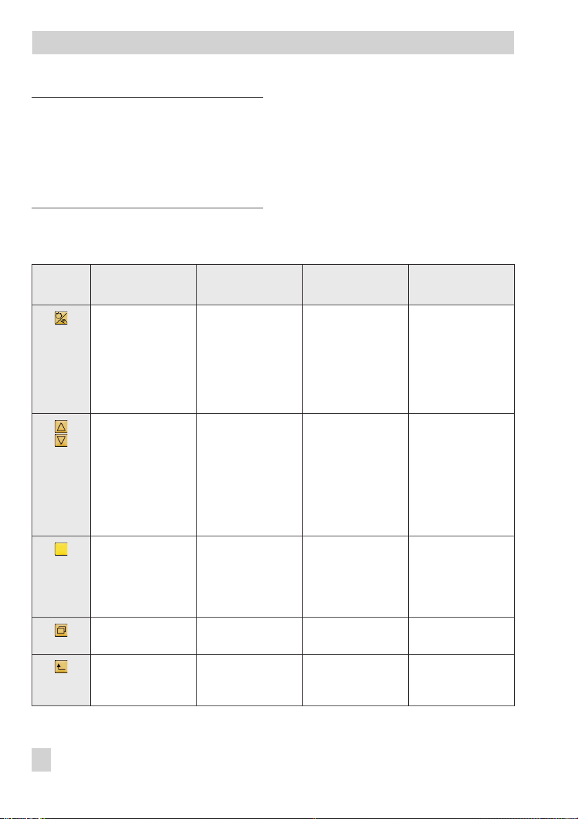
The function of the keys varies depending on
the level/menu which is active. See the table
-
below.
play and the keys on the right are used to
operate the controller on the right display.
Operator
keys Operating level Info menu Operating menu Configuration level
Manual/
automatic
key
Cursor
keys
Switch between
–
manual and
automatic control
mode
– Cascade control:
Open/close controller cascade
– Automatic mode:
Change set point
– Manual mode:
Change
output value
No function –
–
– Browse through
menu and
information
No function –
–
– Browse through a
menu
– Change set point
and control
parameters
Edit individual
–
items of parame
ters
– Browse through
menu, submenu,
configuration
items and parameters
–
Set configuration
items and param
eters
-
-
–
Enter
key
–
Info key
–
Escape
key
14 EB 6495-2 EN
Enter main menu
(operating menu
and configuration
level)
Enter info menu
Confirm restart
after supply
voltage failure
–
Enter menu items–Confirm settings
–
Switch over set
point
–
No function –
–
Return to the ope
rating level
stepwise
–
No function –
-
–
Return to the oper
ating level step
wise
–
–
–
-
–
-
Enter menu,
submenu, configu
ration items and
parameters
Confirm settings
No function –
Return to the oper
ating level step
wise
-
-
-
Page 15
Operating level
6 Operating level
The display in the operating level is ar
ranged depending on the control mode se
The operating level is active while the con
troller is in operation. Key information on
the control process is displayed in this level.
Default reading on display:
Row 1 Actual value PV0 at comparator
Row 2 Error signal +/–e
Row 3 Set point SP1 ... SP4, SPE, SPC
Row 4 Output according to priority
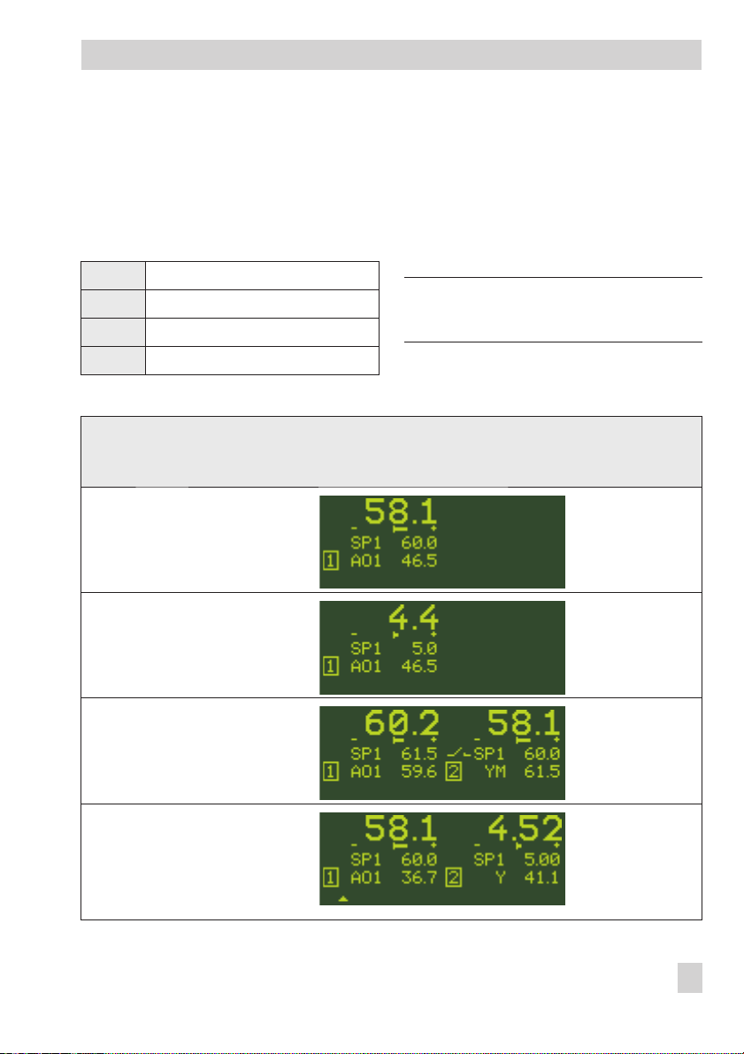
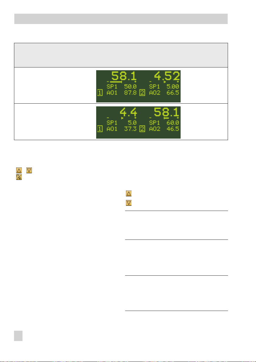
Overview: Default reading on display in the operating level for various control modes
Control mode Operating level (default reading)
M.1-1
1x Fixed set
point/follow-up
control
M.1-2
Ratio control
Controller [1]
Controller [1]
lected. For control modes with two control
lers, the default display has two sections:
Controller [1] on the left display section and
Controller [2] on the right display section.
See overview below.
Note: The default reading can be adapted
as required. See section 9.3.
-
-
-
M.1-3
Cascade
control
M.1-4
Override
control
Slave controller [1]
Main controller [1]
Master controller [2]
Override controller
[2]
EB 6495-2 EN 15
Page 16
Operating level
Overview: Default reading on display in the operating level for various control modes
Control mode Operating level (default reading)
M.1-5
Fixed set
point/follow-up
control
Controller [1]
Controller [2]
M.1-6
Ratio controller
and controller
To operate the controller, use the cursor keys
( , ) and the manual/automatic key
( ) in the operating level. These keys are
located on the left and right of the key
panel. Use the keys on the left to operate the
controller shown in the left display section
and use the keys on the right to operate the
controller shown in the right display section.
The following actions can be performed in
the operating level:
Change the set point→section 6.1
4
Switch over to manual mode and
4
change the output→section 6.2
Open/close cascade (only with cas
4
cade control (setting M.1-3))
section 6.3
Ratio controller [1]
-
→
Controller [2]
6.1 Changing the set point
Change the set point in automatic mode using the cursor keys:
Increase the set point.
Decrease the set point.
Note: The last digit is changed by one value
every time the key is pressed. Hold the key
down to change the value at a faster rate.
6.2 Switching over to manual
mode and changing the
output
Note: The left display for Controller [1] is
shown in the following examples. Conse
quently, the keys on the left are used for op
eration.
-
-
16 EB 6495-2 EN
Page 17
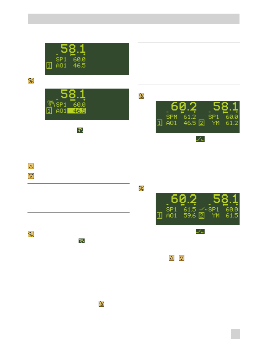
1x Switch to manual mode.
The hand icon appears above the
controller designation [1]/[2].
The currently active manipulated
variable (output) is highlighted:
AO1 = 46.5 %
… Increase the manipulated variable or
… Reduce the manipulated variable.
Note: The last digit is changed by one value
every time the key is pressed. Hold the key
down to change the value at a faster rate.
Operating level
Note: In the following example, the master
controller [2] is shown on the right display
(default). As a result, the manual/automatic
key on the right is used to open/close the
cascade.
1x Close the cascade.
The cascade icon is no longer
displayed when the cascade is
closed.
The output value YM of the master
controller [2] specifies the set point
SPM of the slave controller [1]:
SPM = YM
1x Open the cascade.
Return to automatic mode
1x Return to automatic mode.
The hand icon is no longer dis
played.
-
6.3 Opening/closing cascade
The opening/closing cascade function is
only possible for cascade control (setting
M.1-3).
The cascade is opened and closed by press
ing the manual/automatic key of the
master controller [2].
The cascade icon appears when the
cascade is opened.
The set point of the slave controller
[1] can be changed using the cursor
keys ( , ).
The cascade can also be opened/closed
over a digital input. See configuration item
C.2.2.3 in section 15.2 and section
-
C.2.2.3 in the Configuration Manual
KH 6495-2 EN.
EB 6495-2 EN 17
Page 18
Info menu
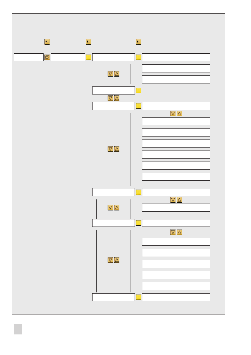
←← ←
---------------------- ----------------------------
→→ →
Operating level Info menu Controller [1] * Set point
Input variable PV, … **
Output **
* If an error message exists, a
submenu is added to the info
menu.
This submenu Error
message is displayed directly
after entering the info level (on
top of the submenu
Controller[1]).
** Only assigned input and
output variables are displayed.
Controller [2] See controller [1]
Inputs/outputs Analog inputs AI1 … 4
Analog inputs [%] AI1 … 4
Analog outputs AO1 … 3
Switch outputs SO1 … 2
Digital inputs DI1 … 4
Digital outputs DO1 … 4
Digital outputs DO5 … DO7
Last events Event 1/x
Event x/x
Diagnosis Diagnosis - 1 (operating time)
Diagnosis - 2 (device temperature)
Diagnosis - 3 (cycle times)
18 EB 6495-2 EN
Diagnosis - 4 (system-internal events)
Diagnosis - 5 (system-internal events)
Diagnosis - 6 (telegram counter)
Versions Firmware
Page 19
Info menu
7 Info menu
Information on the running process and the
controller can be viewed in the info menu.
Usually, there are the following menu items
Controller [1], possibly Controller [2],
Inputs/outputs, Last events, Diagno
sis and Versions. If an error message ex
ists, the menu item Error message is
added to the info menu.
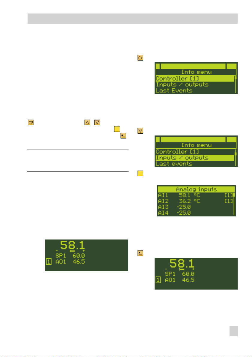
Enter the info menu by pressing the info key
. Use the cursor keys ( , ) to browse
through the menu. Press the enter key to
select a menu item. Press the escape key
to return.
Note: Both the keys on the left and right in
the key panel can be used for the info menu.
Example: A control mode with one controller is configured. An error message does not
exist in the controller.
•
The objective of the example is to find out
the current values of analog inputs AI1
and AI2.
The controller is currently in the operating
level:
-
-
Enter the info menu
1x Change to the info menu.
The menu item Controller [1] is
highlighted on the display.
Activate analog input readings
1x Select menu item Inputs/outputs.
1x Activate menu item Inputs/out-
puts.
The analog inputs are displayed with
their current values.
Return to the operating level
2x Return to the operating level.
EB 6495-2 EN 19
Page 20
Info menu
Notes concerning the readings in the info menu
Menu item Inputs/outputs
•
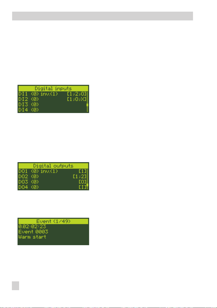
Directly after the digital inputs and outputs, the state of the input/output is indicated:
(0) or (1)
In the case of a reversed digital input or output, the state of the input/output in reversed
form is additionally indicated: inv.(1) or inv.(0)
•
Menu item Last events
The controller assigned to the input/output is indi
cated on the right of the display ([1] or [2]) in the
reading of analog inputs, digital inputs, analog
outputs, switch outputs and digital outputs. If the
input/output is assigned to both controllers, both
controller numbers ([1; 2]) are indicated.
Additional readings apply to the digital inputs
(separate or combined with the controller number):
[O] indicates that the digital input is assigned
4
to an output.
[X] indicates that the digital input activates the
4
key locking.
Additional readings apply to the digital outputs
(separate or combined with the controller number):
[I] indicates that the digital output is activated
4
by a digital input.
[O] indicates that another digital output has
4
been assigned as the source to the digital out
put.
Any events that occur are logged and
time-stamped. The last event is always listed first.
-
-
20 EB 6495-2 EN
Page 21
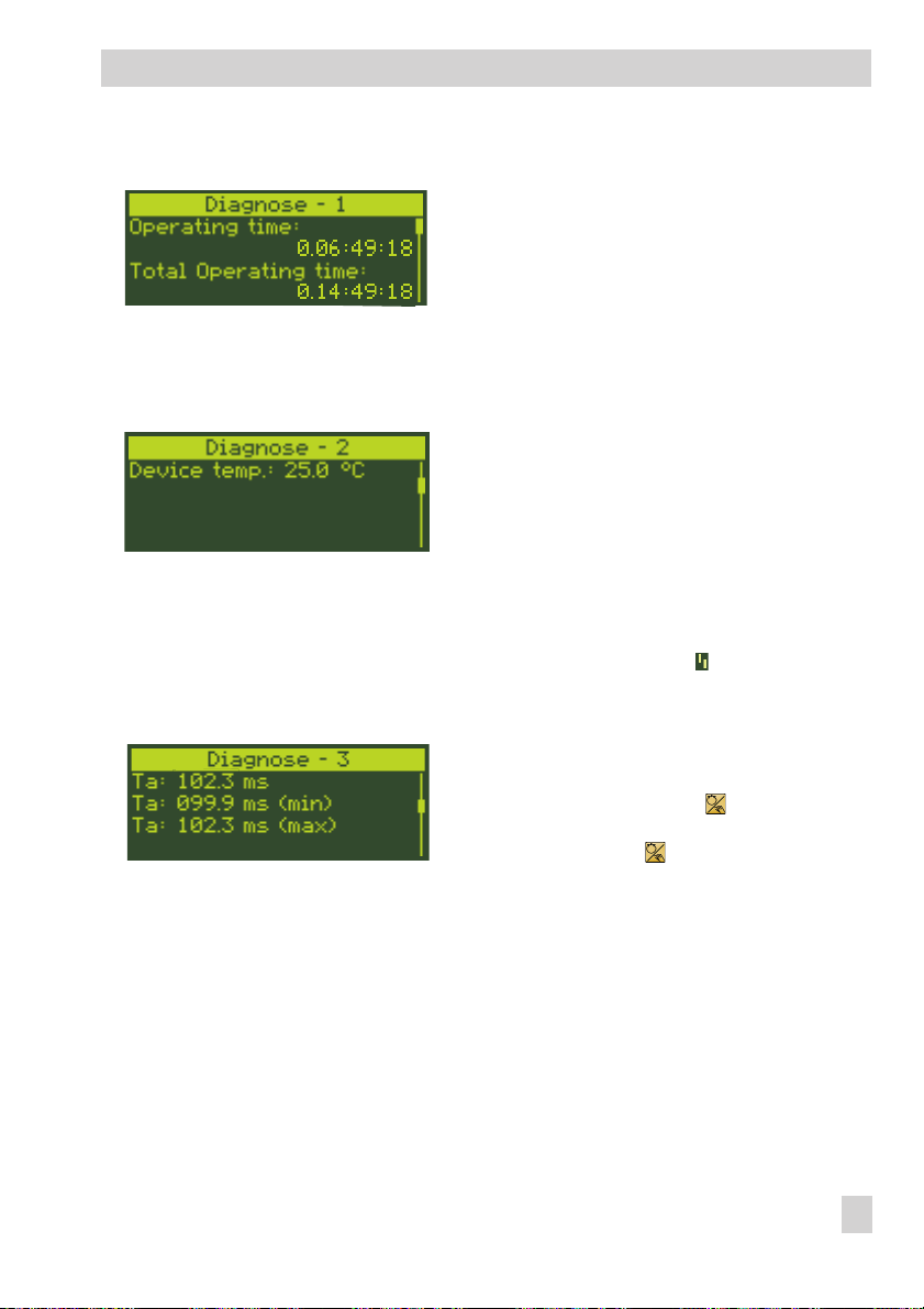
Menu item Diagnosis - 1
•
Menu item Diagnosis - 2
•
•
Menu item Diagnosis - 3
Info menu
Operating time indicates the time the controller
has been operating since the last start-up of the
controller in days.hours:Minutes:Seconds.
The total operating time refers to how long the
controller has been supplied with voltage
(Days.Hours:Minutes:Seconds).
When installing the controller, it is important to
make sure that the permissible ambient tempera
ture (0 to 50 °C) is kept.
The device inside temperature is monitored to pro
tect the controller. If this temperature falls below
0 °C or rises above 60 °C, a message is
generated in Last events and Error messages. If the
temperature inside the controller falls below –5 °C
or rises above 65 °C, a further message is generated and the fault alarm icon blinks in both controller displays.
Reading of current scanning time
The scanning time (min) can be reset by pressing
the left manual/automatic key and the scan
ning time (max) can be reset by pressing the right
manual/automatic key .
-
EB 6495-2 EN 21
Page 22
Operating menu
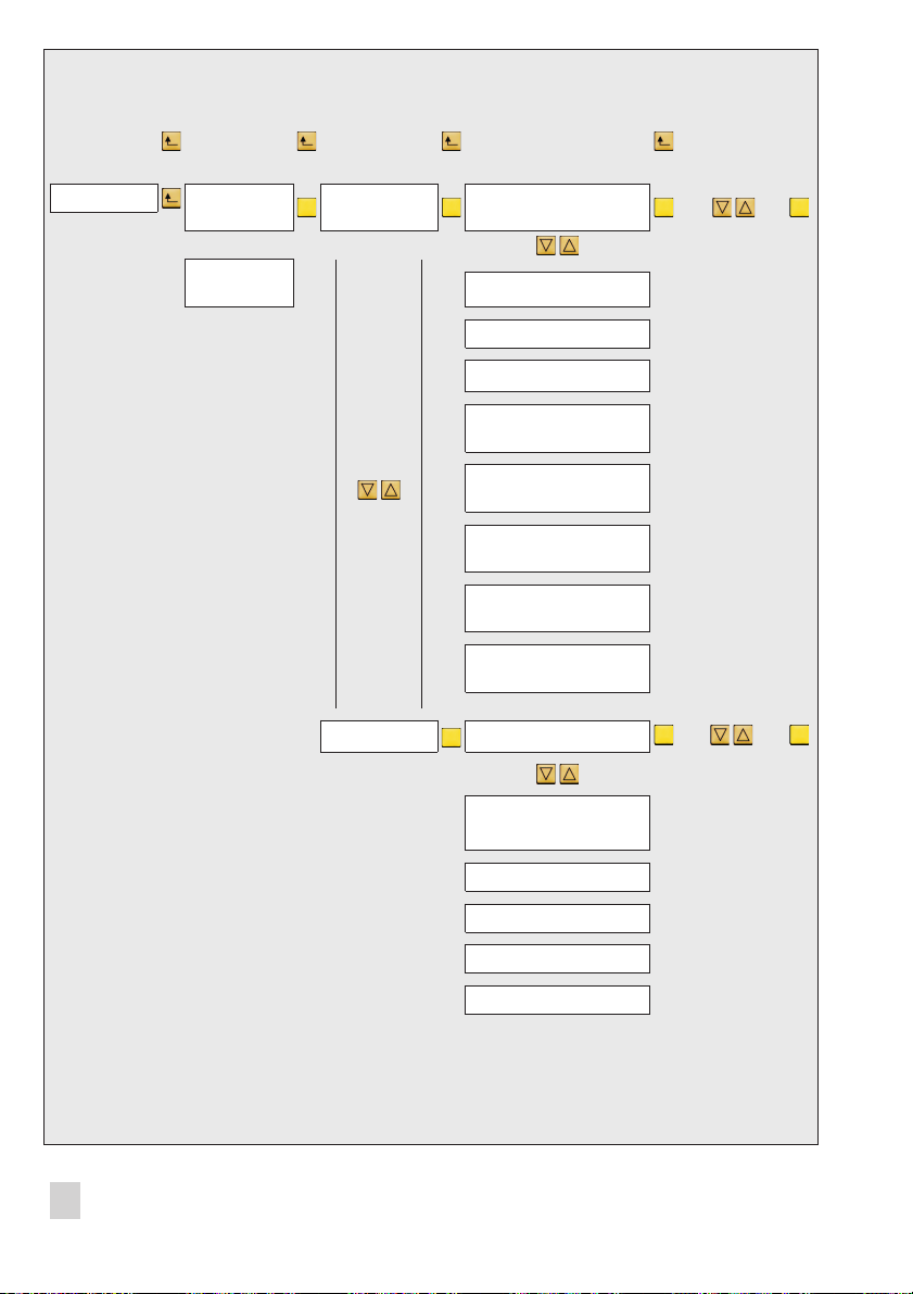
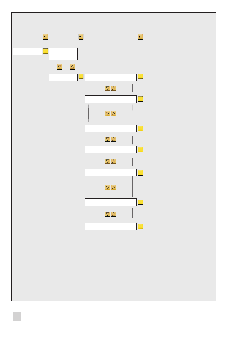
←← ← ←
------------------- --------------------- ----------------------------------
→→ → → ↵
Operating level Op. menu
Controller [1]
Op. menu
Controller [2]
Control
parameters
KP (proportional-action
coefficient)
TN (reset time)
TV (derivative-action time)
Y0 (operating point)
Change
control
parameters
See section 8.2
(derivative-action gain TV.K1)
TV.K
1.P+
(PWM duty cycle SO1.P+)
1.P–
(PWM duty cycle SO1-P–)
2.P+
(PWM duty cycle SO2.P+)
2.P–
(PWM duty cycle SO2.P–)
Set point SP (active set point)
SPI
(current internal set point)
SP1
SP2
SP3
SP4
Switch over
internal/
external set
point
Section 8.3
Switch over
and change
internal set
points
See section 8.4
22 EB 6495-2 EN
Page 23

Operating menu
8 Operating menu
The operating menu consists of the menu
items Control parameters and Set
point. The following actions can be per
formed:
Change control parameters
4
Section 8.2
Switch over internal/external set point
4
4
Section 8.3
→
Switch over and change internal set
points→Section 8.4
Press the enter key to enter the operating
menu. Use the cursor keys ( , ) to
browse through the menu. Press the enter
key to select a menu item.
Note: Both the keys on the left and right of
the key panel can be used for the operating
menu.
→
8.1 Entering the operating
menu
The controller is currently in the operating
level:
Enter the operating menu of Controller [1]
1x Switch to the main menu.
-
Operating menu contr. [1] is
highlighted.
1x Enter Operating menu
contr. [1].
The submenu Control parameters
is highlighted.
Note: Enter the operating menu for Controller [2] in the same way after selecting it
() .
8.2 Changing the control
parameters
After activating the operating menu (see
section 8.1), the control parameters are
changed in the menu item Control pa
rameters. Depending on the control
behavior, the proportional-action coefficient
KP, reset time TN, derivative-action time TV,
derivative-action gain TV.K and operating
point Y0 can be changed:
EB 6495-2 EN 23
-
Page 24
Operating menu
Assignment between control parameters and
control behavior
C.3.1.1
KP
TN •––••
TV
Y0
TV.K
PI
-1P-2PD-3
•••••
––••–
•••••
––••–
PID
-4I-5
Note: If on-off/three-step outputs are con
figured with pulse width modulation (PWM),
the corresponding duty cycles (
SO1.P–, SO2.P+, SO2.P–
SO1.P+,
) can be
changed.
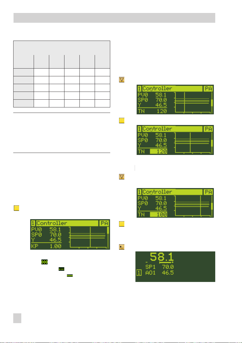
Example: The reset time TN for Controller
[1] is to be changed to 100 s.
Enter the operating menu (see section
4
8.1).
Change the reset time TN
1x Activate the menu item Control pa
rameters.
to 100 % range of the measuring
range is plotted on the right.
The current value of the propor
tional-action coefficient KP is indi
-
-
cated below.
1x Select reset time TN.
-
1x Activate reset time TN.
The current value of the reset time is
highlighted: 120 s
… Keep pressed and change the reset
time TN to 100 s.
-
1x Confirm the reset time.
The actual value at the comparator
PV0 ( ), the set point at the com
parator SP0 ( ) and the manipu
lated variable Y ( ) are indicated
on the left. For ratio control: Actual
ratio PVR, ratio set point SPR and
manipulated variable Y). Their
course within the last minute in the 0
24 EB 6495-2 EN
Return to the operating level
3x Return to the operating level.
-
-
Page 25
Operating menu
8.3 Switching over
internal/external set point
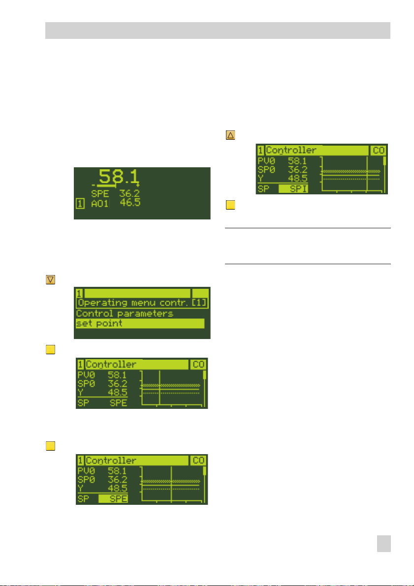
If the external set point SPE (C.2.1.2-1) is
configured, the set point SP is equal to SPE.
The switchover to an internal set point SPI is
performed in the operating menu.
The controller is in the operating level:
Enter the operating menu (see section
4
8.1).
Switchover to the internal set point SPI
1x Select the menu item Set point.
1x Activate the menu item Set point.
The current set point is high
lighted: SPE
1x Select internal set point SPI.
1x Confirm the setting
SPI is now the active set point.
Note: Determining and changing the internal set point is described in Section 8.4.
Cascade control
For cascade control (M.1-3) the cascade
can also be opened and closed by switching
over the set point.
The cascade is opened if the following applies in the slave controller [2]: SP = SPI
The cascade is closed if the following ap
plies in the slave controller [2]: SP = SPM
-
-
The current set point is displayed:
SP = SPE
1x Activate the set point SP.
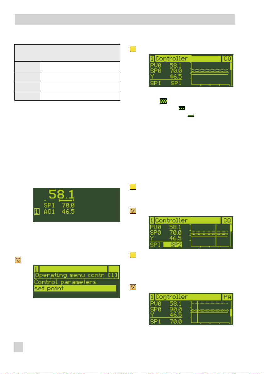
8.4 Switching over between
internal set points and
changing them
In the operating menu, one of the set points
SP1, SP2, SP3 or SP4 can be assigned to
the internal set points SPI, depending on the
configuration.
EB 6495-2 EN 25
Page 26
Operating menu
Required configuration for determining the set
point
SP1
SP2
SP3
SP4
C.2.1.1-1/-2/-3/-4
C.2.1.1-2/-3/-4
C.2.1.1-3/-4
C.2.1.1-4
Example: The controller [1] has two internal
set points SP1 and SP2 (configured with
1C.2.1.1-2).
The set point SP1 is to be switched over to
•
set point SP2.
The set point SP1 is to be kept at 70 while
•
the set point SP2 is to be changed to 100.
The controller is currently in the operating
level:
Enter the operating menu (see section
4
8.1).
1x Activate the menu item Set point
The actual value at the comparator
PV0 ( ), the set point at the com
parator SP0 ( ) and the manipu
lated variable Y ( ) are indicated
on the left. For ratio control: Actual
ratio PVR, ratio set point SPR and
manipulated variable Y). Their
course within the last minute in the 0
to 100 % range of the measuring
range is plotted on the right.
The assignment of the internal set
point (in this case: SPI = SP1) is indicated below.
1x Activate the internal set point.
The current internal set point is highlighted: SP1
1x Set the internal set point SPI = SP2.
-
-
Switchover between internal set points
1x Select the menu item Set point.
26 EB 6495-2 EN
1x Confirm the setting
SP2 is now the active set point.
Change set points SP1 and SP2
1x Select the set point SP1.
Page 27
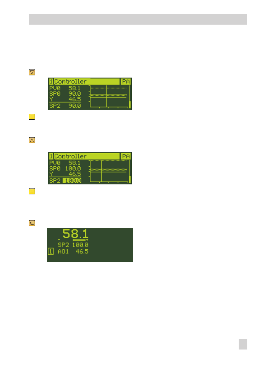
The set point SP1 has the required
value of 70.0 and therefore does not
need to be changed.
1x Select the set point SP2.
1x Activate the set point setting SP2.
The current set point is highlighted:
90.0
… Keep pressed and change the set
point to 100.0.
1x Confirm the set point.
The set point is adopted.
Operating menu
Return to the operating level
3x Return to the operating level.
EB 6495-2 EN 27
Page 28
Configuration level
←← ←
------------------- -------------------------------------
→
Operating level Op. menu
Controller [1]
Configuring the controller,
see section 9.2
2x 2x
Configuration M Control mode
→→
I Input This menu contains the configura
1C Controller [1] These menus contain the configura
2C Controller [2]
O Output This menu contains the configura-
D Communication This menu contains the configura
A General settings This menu contains the configura
Setting the control mode
→
tion of analog inputs AI1 to AI4
and digital inputs DI1 to DI4. See
sec. 15.2 for details.
→
tion of the controller settings for
Controller [1] and Controller [2] as
→
well as input variables, set points,
control functions, restart condition,
controller display and key locking.
See section 15.2 for details.
→
tion of analog outputs AO1 to AO3
and digital inputs DO1 to DO6. See
section 15.2 for details.
→
tion of interfaces. See section 15.2
for details.
→
tion of languages, operation dis
play, operator keys and network
frequency. In addition, the key
number can be entered, a user cali
bration of the analog inputs and
outputs can be performed and the
controller can be reset to the de
fault settings. See section 15.2 for
more details.
-
-
-
-
-
-
-
28 EB 6495-2 EN
Page 29
Configuration menu
9 Configuration menu
In the configuration menu, the controller is
adapted to its control task by changing indi
vidual configuration items and parameters.
The configuration menu is subdivided into
various menus and submenus. The
submenus contain the individual configura
tion items and parameters. Section 15.2 in
cludes an overview of all possible settings
that can be made.
The Configuration Manual KH 6495-2 EN
contains detailed descriptions on individual
configuration items as well as other helpful
information.
Operation within the configuration level is
performed using the cursor keys, ( , ),
enter key ( ) and escape key ( ).
Note: Both the keys on the left and right of
the key panel can be used in the configuration level.
If the controller is to be newly configured,
we recommend keeping the following con
figuration sequence:
1. Set the control mode, e.g. M.1-1
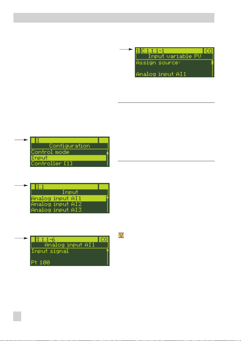
2. Set the input, e.g. I.1.1-6
3. Assign input to controlled variable, e.g.
C.1.1.1-1
4. Change the set point, e.g. C.2.1.1
5. Determine the control algorithm, e.g.
C.3.1.1
6. Assign the output, e.g. O.1.1-1
7. Set the output signal, e.g. O.1.2-1
-
8. Set the operating direction, e.g.
O.1.3-1
9. Set the restart condition, e.g. C.4.1-0
Configuration Manual KH 6495-2 EN con
tains further information.
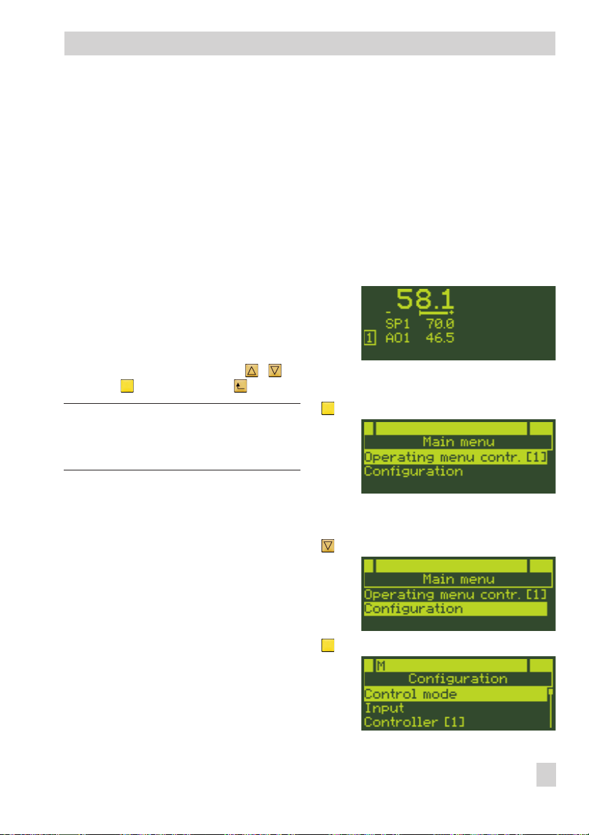
9.1 Entering the configuration
-
-
The controller is currently in the operating
level:
Enter the configuration level
level
1x Change to the main menu.
The Operating menu Contr. [1]
is highlighted.
1x Select Configuration menu.
1x Enter Configuration menu.
-
EB 6495-2 EN 29
Page 30
Configuration menu
The menu M Control mode is
highlighted.
9.2 Configuring the controller
The controller is configured by setting the
configuration items and associated parame
ters.
Each configuration item has its own code,
which gives information on its position in the
configuration level.
Example: The configuration item Input
signal has the code I.1.1.
I
Menu I Input
4
→
configuration item C.1.1.1 Input vari
able PV:
Note: Some configuration items as well as
the parameters can only be set if certain set
tings have already been made in the con
troller configuration. The required settings
for the controller configuration are de
scribed in the configuration list (section
15.2) and in the Configuration Manual
KH 6495-2 EN.
-
-
-
-
I.1→Submenu 1 Analog
4
input AI1
I.1.1
4
Input signal with the setting -6
Pt 100
For control modes with two controllers, the
controller number “1C…“ (Controller [1])
and “2C…“ (Controller [2]) is added to dis
tinguish between the controllers, e.g. for
30 EB 6495-2 EN
Configuration item 1
→
9.2.1 Setting configuration items
1. Read the code of the configuration item
that you want to change from the configuration list (section 15.2).
2. Find the position in the configuration
level. See the example in section 9.2.2.
Select and set the configuration item
… If the configuration item that you
want to set is not in the menu
M Control mode, select the menu
required:
I Input
C Controller [1]/[2]
O Output
D Communication
A General settings
-
Page 31

Configuration menu
1x Enter menu.
The first submenu is highlighted.
… If the configuration item that you
want to set is not in the highlighted
submenu, select the required
submenu.
1x Enter submenu.
The first configuration item of the
submenu is displayed together with
its current setting.
Note: The menu
sists of two submenu levels. To view the indi
vidual configuration items, the submenus
must be entered one after the other.
… If you want to set another configura-
tion item or parameter other than the
one displayed, select the required
configuration item/parameter.
1x Activate configuration item/parame-
ter.
Change configuration item/parame
ter.
1x Confirm setting.
Return to the operating level
… Return to the operating level
stepwise.
C Controller
partly con
-
9.2.2 Configuration example
Based on a default setting (1x Fixed set
point/follow-up control M.1-1), the analog
input AI1 is to be set to Pt 1000. The mea
suring range is to be 0 to 200 °C.
ü The code of the configuration item to
determine the input signal is I.1.1,
see configuration list (section 15.2).
Lower and upper range values are
set in the AI1.MIN and AI1.MAX
parameters. Both parameters are as
-
-
signed to the configuration item
I.1.1.
ü The following position in the configu-
ration level can be found using the
code of the configuration item:
I
4
I.1
4
I.1.1→Configuration item 1
4
Note: The analog input AI1 can only be
configured as a Pt 1000 input when the DIP
switches are positioned for “Pt 100/
Pt 1000“.
Both DIP switches AI1 (at the side of the con
troller case) must set to the position “Pt 100/
Pt 1000“ (see Fig. 3 on page 12).
Menu I Input
→
Submenu 1
→
Analog input AI1
Input signal
-
-
-
EB 6495-2 EN 31
Page 32

Configuration menu
The controller is currently in the operating
level:
Enter the configuration level, see sec
4
tion 9.1.
Configure the input signal
1x Select menu I Input.
1x Enter menu I Input.
The submenu I.1 Analog input
AI1 is highlighted.
1x Enter submenu I.1 Analog in
put AI1.
The input signal setting is high
lighted: Pt 100
1x Change setting to I.1.1-7
(Pt 1000).
-
1x Confirm new setting.
Set the measuring range
1x Select AI1.MIN Lower range
value parameter.
The lower range value is already set
to 0 °C and does not need to be
changed.
1x Select AI1.MAX Upper range
value parameter.
-
-
The configuration item I.1.1 Input
signal is displayed together with the
current setting: I.1.1-6 = Pt 100
1x Activate the configuration item I.1.1
Input signal.
32 EB 6495-2 EN
1x Activate AI1.MAX Upper range
value parameter.
The upper range value setting is
highlighted: 100.0 °C
… Keep pressed and change the upper
range value to 200 °C.
1x Confirm new setting.
Page 33

Configuration menu
Return to the operating level
4x Return to the operating level.
9.3 Adapting the display
The display can be adapted in the following
ways:
Change controller display
4
section 9.3.1
Set up additional display→sec-
4
tion 9.3.2
Switch Controller [1] and Controller [2]
4
displays→section 9.4
→
9.3.1 Changing the controller
display
The controller display is adapted in the
submenu C.5 Controller display of the
corresponding Controller [1] or [2] (1C.5 or
2C.5).
Signals can be selected for each row which
are to be displayed in the operating level.
The type of representation (numerical, bar
graph, etc.) can additionally be determined
for the rows 4 and 5.
The following table shows the settings neces
sary for adapting the display (see section
15.2 for details).
Select signal
Row 1
Row 2
Row 3
Row 4
Row 5
Example: Based on the default setting (1x
fixed set point/follow-up controller M.1-1)
the output AO1 for Controller [1] in row 5 is
to be displayed as a bar graph.
According to the table above, the setting is
made in menu 1C Controller [1] in the
configuration items 1C.5.6 Row 5 and
1C.5.7 Row 5 representation.
The controller is currently in the operating
level:
Enter the configuration level, see sec
4
tion 9.1.
Configure row 5
2x Select menu 1C Controller [1].
-
C.5.1-1...4
C.5.2-1...2
C.5.3-1...3
C.5.4-1...41 C.5.5-1...6
C.5.6-1...41 C.5.7-1...6
Select type of
representation
–
–
–
-
EB 6495-2 EN 33
Page 34

Configuration menu
1x Enter menu 1C Controller [1].
The submenu 1C.1 Input
variables is highlighted.
4x Select submenu 1C.5 Controller
display.
1x Enter submenu 1C.5 Controller
display.
The configuration item 1C.5.1 Row
1 is displayed together with the cur
rent setting: 1C.5.1-1 = Actual
value PV0 at comparator
5x Select configuration item 1C.5.6
Row 5.
2x Change setting to 1C.5.6-2
(Output AO1).
1x Confirm setting.
Configure row representation
1x Select configuration item 1C.5.7
Row 5 representation.
The currently active setting is displayed: 1C.5.7-1 = Numerical
1x Activate configuration item 1C.5.7.
The currently active setting is highlighted: Numerical
-
2x Change setting to 1C.5.7-3 (Bar
graph).
The currently active setting is dis
played: 1C.5.6-0 = Off
1x Activate configuration item 1C.5.6.
The currently active setting is
highlighted: Off
34 EB 6495-2 EN
1x Confirm setting.
-
Page 35

Configuration menu
Return to the operating level
4x Return to the operating level.
The Output AO1 is displayed in
row 5 as a bar graph.
9.3.2 Setting up additional
display
If rows 1 to 5 in the display are all assigned
and further variables are to be displayed,
an additional display can be added. The
additional display is activated in the
submenu A.2 Operation display. Five
additional rows are available. The additional display is set in the submenu C.6 Ad-
ditional display of the corresponding
Controller [1] or [2] (1C.6 or 2C.6).
Note: For control modes with two controllers
M.1-3/-4/-5/-6
(
with additional display or both controllers
without additional display can be config
ured. If the additional display of Controller
[1] , for example, covers the display of Con
troller [2], the display of Controller [2] can
be briefly viewed by pressing one of the cur
sor keys , or the manual/automatic
key in the operating level.
It is also possible to display the additional
displays of both controllers.
) either one controller
-
To implement the additional display in the
display, it must be activated in the submenu
A.2 Operation display.
The following table indicates the settings
necessary to set up the additional display
(see section 15.2 for details).
Select row
representa
tion
-
Row 1
Row 2
Row 3
Row 4
Row 5
Select
variable
C.6.1-1...41 C.6.2-1...6 C.6.1-0
C.6.3-1...41 C.6.4.1...6 C.6.3-0
C.6.5-1...41 C.6.6.1...6 C.6.5-0
C.6.7-1...41 C.6.8-1...6 C.6.7-0
C.6.9-1...41 C.6.10-1...6 C.6.9-0
Example: Based on the example in section
9.3.1, an additional display is to be set up
for Controller [1] in the right display section.
Its fourth row is to display the output AO2
numerically inverted.
According to the table above, the setting is
made in menu 1C Controller [1] in the
configuration items 1C.6.7 Row 4 and
1C.6.8 Row 4 representation. To acti
vate the additional display, the configura
tion item A.2 Operation display must be
-
configured.
The output Y of the controller is to be as
-
signed to the Output AO2 as a source.
The controller is currently in the operating
level.
Hide row
-
-
-
EB 6495-2 EN 35
Page 36

Configuration menu
Enter the configuration level, see sec
4
tion 9.1.
Assign source for Output AO2
3x Select menu O Output.
1x Enter menu O Output.
The submenu O.1 Analog
output AO1 is highlighted.
1x Select submenu O.2 Analog
output AO2.
-
1x Activate configuration item O.2.1.
The currently active setting is high
lighted: Off
1x Change setting to O.2.1-1
(Controller [1] output Y).
1x Confirm setting.
Set up additional display
2x Exit menu O Output.
1x Select menu 1C Controller [1].
1x Enter menu 1C Controller [1].
-
1x Enter submenu O.2 Analog out
put AO2.
The configuration item O.2.1 As
sign source is displayed together
with the currently active setting:
O.2.1-0 = Off
36 EB 6495-2 EN
-
The menu item 1C.1 Input
variables is highlighted.
5x Select menu item 1C.6 Additional
display.
-
Page 37

Configuration menu
1x Activate menu item 1C.6.
The configuration item 1C.6.1 Row
1 is displayed with its currently ac
tive setting: 1C.6.1-0 = Off
3x Select configuration item 1C.6.7
Row 4.
The currently active setting is displayed: 1C.6.7-0 = Off
1x Activate configuration item 1C.6.7
Row 4.
The currently active setting is
highlighted: Off
3x Change setting to C.6.7-3
(Output AO2).
The currently active setting is dis
played: 1C.6.8-1 = Numerical
1x Activate configuration item 1C.6.8
Row 4 representation.
The currently active setting is high
lighted: Numerical
-
1x Change setting to 1C.6.8-2
(Numerical, inverted).
1x Confirm setting.
Activate additional display
2x Return to menu list.
3x Select menu item A General
settings.
-
-
1x Confirm setting.
1x Select configuration item 1C.6.8
Row 4 representation.
1x Enter menu item A General set
tings.
EB 6495-2 EN 37
-
Page 38

Configuration menu
The submenu A.1 Language/
Sprache is highlighted.
1x Select submenu A.2 Operation
display.
1x Enter submenu A.2 Operation
display.
The configuration item A.2.1 Left
display is displayed together with
the currently active setting: A.2.1-1
= Controller [1]
1x Select submenu A.2.2 Right
display.
The currently active setting is dis
played: Right display = Off
1x Enter submenu A.2.2 Right dis
play.
The currently active setting is high
lighted: Off
1x Change setting to A.2.2-2
(Controller [1] additional reading).
1x Confirm setting.
Return to the operating level
4x Return to the operating level.
In the additional reading in the display, the Output AO2 is displayed
numerically inverted.
9.3.3 Switching Controller [1]
and Controller [2] displays
The left display is assigned to Controller [1]
and the right display to Controller [2] in the
default setting. If required, both controller
displays can be switched around so that the
-
-
left display is for Controller [2] and the right
display is for Controller [1].
Example: For cascade control (setting
M.1-3) the left display is assigned to the
slave controller and the right display is
assigned to the master controller. The dis
plays are to be switched so that the master
controller (Controller [2]) is shown in the left
display ad the slave controller (Controller
[1]) is shown in the right display. To do this,
the submenu settings A.2.1 Left display
-
38 EB 6495-2 EN
Page 39

Configuration menu
and A.2.2 Right display must be
changed.
Note: Before Controller [1] can be assigned
to the right display, it must first be removed
from the left display as one controller cannot
be assigned to both displays at the same
time.
The controller is currently in the operating
level.
Enter the configuration level, see sec-
4
tion 9.1.
Deactivate left display
6x Select menu A General settings.
1x Select submenu A.2 Operation
display.
1x Enter submenu A.2 Operation
display.
The configuration item A.2.1 Left
display is displayed together with
the currently active setting: A.2.1-1
= Controller [1]
1x Activate configuration item A.2.1
Left display.
The currently active setting is highlighted: Controller [1]
1x Change setting to A.2.1-0 (Off).
1x Enter A General settings.
The submenu A.1
Language/Sprache is
highlighted.
1x Confirm setting.
EB 6495-2 EN 39
Page 40

Configuration menu
Configure right display
1x Select configuration item A.2.2
Right display.
1x Activate configuration item A.2.2
Right display.
The currently active setting is high
lighted: Controller [2]
2x Change setting to A.2.2-1
(Controller [1]).
1x Confirm setting.
Configure left display
1x Select configuration item A.2.1 Left
display.
2x Change setting to A.2.1-3
(Controller [2]).
1x Confirm setting.
Return to the operating level
-
4x Return to the operating level.
The left display is now assigned to
Controller [2] and Controller [1] is
assigned to the right display.
1x Activate configuration item A.2.1
Left display.
The currently active setting is high
lighted: Off
40 EB 6495-2 EN
-
Page 41

Locking the controller
10 Locking the controller
It is possible to prevent unauthorized access
to the controller. There are three ways to im
plement the locking of the controller:
Lock the operating level→section 10.1
4
Lock all keys over the digital input
4
section 10.2
Activate key number operation
4
section 10.3.
→
→
10.1 Locking the operating level
Switchover between manual and automatic
mode as well as changes to the set point for
both Controller [1] and Controller [2] can
be locked independently from one another.
Locking is performed in submenu C.7 Op-
erator keys of either Controller [1] or [2]
by setting the configuration items C.7.2-1
Lock manual/auto key = On and/or
C.7.3-1 Lock set point keys = On.
Example: The set point adjustment of Controller [1] is to be locked.
The controller is currently in the operating
level.
Enter the configuration level, see sec
4
tion 9.1.
1x Enter menu 1C Controller [1].
The submenu 1C.1 Input vari
ables is highlighted.
-
-
6x Select submenu 1C.7 Operator
keys.
1x Enter submenu 1C.7 Operator
keys.
The configuration item 1C.7.1 In
vert manual output value is dis
played with its currently active setting.
2x Select configuration item 1C.7.3
Lock set point keys.
1x Activate configuration item 1C.7.3
Lock set point keys.
The currently active setting is high
lighted: Off
1x Change setting to 1C.7.3-1 (On).
-
-
-
-
Activate locking
2x Select menu 1C Controller [1].
1x Confirm setting.
4x Return to the operating level.
Set point adjustment is locked in au
tomatic mode in the operating level.
EB 6495-2 EN 41
-
Page 42

Locking the controller
Note: The operating menu Controller [1] is
not affected by the locking function. The set
point can still be changed (see section 8.4).
10.2 Locking all keys over a
digital input
The operator keys are locked when the se
lected digital input is active.
The key locking is set in the menu A Gen
eral settings in configuration item A.3.1.
Example: The operator keys are to be
locked by the active digital input DI2.
The controller is currently in the operating
level.
Enter the configuration level, see sec-
4
tion 9.1.
Activate locking
6x Select menu A General settings.
1x Activate menu A General set
tings.
2x Select submenu A.3 Operator
-
-
keys.
1x Enter submenu A.3 Operator
keys.
The configuration item A.3.1 Lock
all keys is displayed with its cur-
rently active setting: Off
1x Activate configuration item A.3.1
Lock all keys.
The currently active setting is high
lighted: Off
2x Change setting to A.3.1-2 (With
digital input DI2).
-
-
42 EB 6495-2 EN
1x Confirm setting.
4x Return to the operating level.
Page 43

Locking the controller
The operator keys are locked when
the digital input DI2 is active. Set
tings cannot be changed.
10.3 Activating key number
operation
When key number operation is activated,
control parameter settings in the operating
menu as well as settings in the configuration
level can only be changed after entering a
key number. The activation of the key
number operation remains effective until the
configuration level is left.
Note: The key number can be entered in the
range between 0 and 9999.
It is advisable to note down the key number
as it is needed to deactivate the key number
operation as well.
Key number operation is activated in the
configuration level in the configuration item
A.4.1:
The controller is currently in the operating
level.
Enter the configuration level, see sec
4
tion 9.1.
Activate key number operation
-
-
5x (control modes with one controller)
6x (control modes with two controllers)
Select menu A General Settings.
1x Enter menu A General Settings.
The submenu A.1 Lan-
guage/Sprache is highlighted.
3x Select submenu A.4 Key number.
1x Enter submenu A.4 Key number.
The configuration item A.4.1 Key
number operation is displayed
together with the currently active set
ting: A.4.1-0 = Off
1x Activate configuration item A.4.1
Key number operation.
The currently active setting is
highlighted: Off
EB 6495-2 EN 43
-
Page 44

Locking the controller
1x Change setting to A.4.1-1 (On).
1x Confirm setting.
1x Select Key number parameter.
1x Activate Key number parameter.
The current user key number (0 =
default) is highlighted.
… Change the key number as required
(ranging from 0 to 9999).
tion level can only be performed af
ter the key number has been entered
using the cursor key ( ) and con
firmed by pressing the enter key
().
Deactivate key number operation
Key number operation is deactivated by set
ting A.4.1-0.
-
-
Note: An overriding service key number is
specified on the last page of the printed
instructions which allows configuration settings and parameters to be changed regardless of user key number operation.
To avoid the unauthorized use of the service
key number, it should be removed from the
printed instructions and kept in a safe place.
-
1x Confirm key number.
4x Return to the operating level.
From now on, changes to control pa
rameter settings in the operating
menu and changes in the configura
44 EB 6495-2 EN
-
-
Page 45

User calibration
11 User calibration
The analog inputs and outputs are fac
tory-calibrated.
A system-related user calibration can com
pensate for long cables, small wire
cross-sections or tolerances of measuring
transducers and actuators. The calibration is
similar in principle to a scaling. The gradi
ent and zero shift are automatically calcu
lated by the controller.
Note: The function
controller to be reset to factory-calibration
settings.
A.21.1-2
-
allows the
11.1 Calibrating analog inputs
Connect signal source at the input.
4
Zero
Enter menu item Zero depending on the
4
analog input and signal type, e.g.
A.20.1.9 for Analog input AI1 and
Pt 100 (see section 15.2).
Set the signal source to the initial value.
4
If the input value is within the range that
can be calibrated, the selection bar is
displayed.
Press the enter key ( ) to confirm the
4
value. The zero point is calibrated.
End value
Enter menu item End depending on the
4
analog input and signal type, e.g.
A.20.1.10 for Analog input AI1 and
Pt 100 (see section 15.2).
Set the signal source to the end value.
4
If the input value is within the range that
can be calibrated, the selection bar is
displayed.
Press the enter key ( ) to confirm the
4
value. The end value is calibrated.
-
11.2 Calibrating analog outputs
Connect a precision measuring instru
4
-
-
ment at the output.
Zero
Enter menu item Zero depending on the
4
analog output and signal type, e.g.
A.20.5.1 for Analog output AO1 and
mA signal (see section 15.2).
Set the output signal using the cursor
4
keys ( and ) to the initial value. If
the output value is within the range that
can be calibrated, the selection bar is
displayed.
Press the enter key ( ) to confirm the
4
value. The zero point is calibrated
(display: 0.0 %).
End value
Enter menu item End depending on the
4
analog output and signal type, e.g.
A.20.5.2 for Analog output AO1 and
mA signal (see section 15.2).
Set the output signal using the cursor
4
keys ( and ) to the final value.
If the output value is within the range
that can be calibrated, the selection bar
is displayed.
Press the enter key ( ) to confirm the
4
value. The zero point is calibrated (dis
play: 100.0 %).
-
-
EB 6495-2 EN 45
Page 46

Fault alarms
12 Fault alarms
Incoming and outgoing error messages are
time-stamped and saved in the last events
The fault alarm icon is displayed when a
fault alarm has been registered.
list (info menu).
The following error table contains possible
causes and the recommended action.
Note: We recommend for any errors not de
scribed in detail to switch off the power sup
Possible sources of error are displayed in
the info menu on selecting the menu item
ply and to wait approx. five seconds before
switching it on again.
Error messages. If several errors exist,
use the cursor keys ( , ) to browse
through the errors.
As soon as an error has been corrected, it is
removed from the list of errors and is no
longer displayed.
The digital outputs DO5 and DO6 can be
configured so that they are activated when a
sensor/signal error or communication error
occurs. See configuration item O.10.1 and
O.11.1 in section 15.2.
Error message Possible cause Recommended action
AI1(2, 3, 4) Wrong switch position
AI1(2, 3, 4) below range
AI1(2, 3, 4) above range
C1(2)–SPC below range
The position of the two DIP
switches for the analog input
configuration is not identical.
The input signal is 5 % below
the lower value of the rated
signal range.
The input signal is 5 % above
the upper value of the rated
signal range.
The given set point is lower than
the lower measuring range
value AI1(2, 3, 4).MIN of the
analog input assigned to the
controlled variable PV.
Re-position DIP switches (see
section 5.2).
• Check input signal setting.
• Check the sensor lead for
sensor/wire breakage or for
a short circuit.
• Check electrical connection
to terminal strip 1 (analog
inputs). See section 4.
Check value
-
-
46 EB 6495-2 EN
Page 47

Fault alarms
Error message Possible cause Recommended action
C1(2)–SPC above range
Internal temperature
sensor defective
Internal temperature
Temperature too low (0 °C)
Internal temperature
Temperature too high (60 °C)
Internal temperature
Temperature too low (–5 °C)
Internal temperature
Temperature too high (65 °C)
Communication error AI1(2, 3, 4)
Timeout
Communication error C1(2)–
SPC Timeout
The given set point is higher
than the upper measuring range
value AI1(2, 3, 4).MAX of the
analog input assigned to the
controlled variable PV.
The permissible ambient temper
ature between 0 and 50 °C has
not been kept.
No write access given within the
timeout for the signal monitoring
of the interface assigned to an
analog input.
No write access given within the
timeout for the signal monitoring
of the interface assigned to Con
troller [1] or [2].
Check value
Send controller back to
SAMSON AG for repair.
Check the ambient tempera
•
ture.
Check location of installation.
•
• Check timeout setting
(AI1(2, 3, 4).TOUT parameter in configuration
item I.1(2, 3, 4).1).
• Check interface (see section 13).
• Check timeout setting
(SPC.TOUT parameter in
-
configuration item
C.2.1.6).
• Check interface (see sec
tion 13).
-
-
EB 6495-2 EN 47
Page 48

Interfaces
13 Interfaces
The TROVIS 6495-2 Controller is equipped with an infrared interace. In addition, it can be
fitted with one of two optional interface boards. Data can be transferred between
TROVIS-VIEW and the Controller over the interfaces. Refer to section 14.5.
Infrared interface: Infrared adapter (RS-232)
4
RS-232/USB interface board : Connecting cable RJ12/D-sub 9-pin (RS-232)
4
RS-485/USB interface board: USB cable (5-pin mini-B – USB type A)
4
or
USB cable (5-pin mini-B – USB type A)
1
TROVIS 6495
2
3
1 RJ12 jack (RS-232/USB interface board)
2 Infrared interface
3 USB interface (RS-232/USB and RS-485/USB
interface boards)
4 USB cable (mini-B, 5-pin – USB type A)
5 Infrared adapter (RS-232)
6 Connecting cable RJ12/D-sub 9-pin (RS-232)
7 Memory pen (RS-232), only in combination with
RS-232/USB interface board
8 Modular adapter RJ12/D-sub 9-pin (RS-232)
9 COM port (RS-232) on the computer
10 USB port on the computer
Note: By using the USB 1.1 serial adapter, the USB port of the computer can be used in place of the COM port
(RS-232) when Windows
®
2000, Windows®XP, Windows®Vista or Windows®7 is installed on the computer.
7
6
8
5
4
USB 1.1 serial adapter
Note: The order numbers for the accessories
are listed in section 2.2.
9
10
Fig. 4 · Data transmission
48 EB 6495-2 EN
Page 49

Interfaces
13.1 Infrared interface
The infrared interface can be accessed from the front of the controller. It is located above the
SAMSON logo (Fig. 5).
An infrared adapter is required for data transmission between the serial RS-232 port of the
computer and the infrared interface integrated in the controller. A bracket ensures that the
adapter is properly aligned.
˚
25
0.7 m
1 Infrared adapter
2
1
2 COM port on the computer
(COM or with
USB 1.1 serial adapter connected
to the USB port)
Fig. 5 · Connecting an infrared adapter
Note: To ensure data transmission functions properly, place the infrared adapter so that the
distance to the infrared interface does not exceed 0.7 m and that the max. angle 25° is kept.
EB 6495-2 EN 49
Page 50

Interfaces
13.2 Optional interface boards
The controller can optionally be fitted with either a RS-232/USB interface board or a
RS-485/USB interface board. These boards can be retrofitted.
Installing the interface board
The optional interface board is fitted at the back of the controller.
1. Press the two catches on the blank cover inwards
at the same time. Pull out the blank cover.
2. Push the interface board with cover into the open
ing, making sure that the interface board rests on
the guide intended for it and that the cover locks
in place.
Fig. 6 · Blank cover at the back of the controller
13.2.1 RS-232/USB interface board
USB
RS-232
RS-232:
Fig. 7 · RS-232/USB interface board
GND
DTR
TX
DCD
RX
+5V
16
Upgrading the controller with the optional RS-232/USB interface board (slave) (order
no. 1400-9917) allows data transmission over the RJ12 jack or over the USB port. In addi
tion, a memory pen (see section 14.7) can be plugged into the RJ12 jack.
50 EB 6495-2 EN
-
Page 51

Interfaces
The RS-232/USB interface board (slave) includes:
RS-232 interface (RJ12 jack)
4
USB interface (5-pin mini-B port) (slave)
4
RS-232 data transmission is implemented using SSP or Modbus RTU protocol.
The protocol of the RS-232 interface is set at the controller in the configuration item D.2.1.
The first time the USB interface is used to connect the controller to the computer, the device
driver is demanded. The driver is included on the TROVIS-VIEW CD-ROM (USB Driver >
USB-RS232 Adapter 8812-2001) or can be downloaded from the Internet at
www.samson.de > Services > Support & Downloads > USB driver.
13.2.2 RS-485/USB interface board
To integrate the controller into a communications network, the controller can be fitted with an
optional interface board RS-485 Modbus RTU (order no. 1400-9918). The USB connection
can be used to transfer data using TROVIS-VIEW.
The RS-485/USB interface board includes:
RS-485 interface (4 terminals)
4
USB interface (5-pin mini-B port) (slave)
4
USB
RS-485
RS-485:
AR
BR
BTR
ATR
Fig. 8 · RS-485/USB interface board
4-wire 2-wire
RX
TX RX/TX
2-Leiter4-Leiter
Bus termination
slide switch
OFF ON
RX
OFF ON
TX
2-/4-wire operation
slide switch
42
EB 6495-2 EN 51
Page 52

Interfaces
RS-485 data transmission is implemented using SSP or Modbus RTU protocol. Slide switches
are used to set the 2-/4-wire operation and to activate bus termination.
The protocol of the RS-485 interface is set at the controller in the configuration item D.3.1.
The first time the USB interface is used to connect the controller to the computer, the device
driver is demanded. The driver is included on the TROVIS-VIEW CD-ROM (USB Driver >
USB-RS232 Adapter 8812-2001) or can be downloaded from the Internet at
www.samson.de > Services > Support & Downloads > USB driver.
Network structure
Fig. 9 shows an example for the setup of an automation system with data exchange using
Modbus protocol. A maximum of 246 devices can be addressed. First of all, a converter
must connected to the computer to convert the RS-232 signal issued by the computer into a
RS-485 signal. A repeater must be used if the line exceeds a length of 1200 m or if more
than 32 participants are connected to the bus. No more that three repeaters should be connected in series. As a result, lines of 4800 m can be achieved. Ten of these lines can be connected in parallel on extending the network.
Bus terminators must be fitted at the beginning and end of every section, e.g. between the
converter and repeater.
1 Converter
2 Repeater
3 Modbus device, e.g. TROVIS 6495-2
RS-485
1
RS-485
RS-232
RS-232
3
2
RS-485
RS-485
max.
30
max.
30
3
Fig. 9 · Network structure with converters and repeaters
3
3
52 EB 6495-2 EN
2
RS-485
RS-485
max.
30
3
max.
31
3
2
RS-485
RS-485
3
3
Page 53

13.3 SAMSON memory pen
Interfaces
Note: The memory pen can only be used when the controller is fitted with a RS-232/USB in
terface board.
The SAMSON memory pen serves as a data carrier and is able to load and store data in its
non-volatile memory.
The memory pen can be loaded with data configured in TROVIS-VIEW and the settings
transferred to one or several controllers of the same type and version. In the same way, the
memory pen can be used to upload data from the controller allowing you to simply copy the
configuration data from one controller to another controller of the same type and version.
Data transmission between TROVIS-VIEW and memory pen
1. Plug memory pen into the RJ12 jack at the RS-232/USB board of the controller.
The following appears on the display when the controller recognizes the memory pen:
In the top row of the display, the device type whose data is contained on the memory
pen is indicated. You can select wheter the data from the controller are to be uploaded
onto the memory pen or whether the data from the memory pen are to be downloaded
to the controller. If the memory pen contains, for example, data from another device
type, the option to download from the pen does not appear. If the memory pen is
write-protected, the option to upload data does not appear.
2. Select option ( , ):
6495 >> Memory pen: Data are uploaded from the controller to the memory pen.
Memory pen >> 6495: Data are downloaded from the memory pen to the controller.
3. Confirm setting ( ).
Data transmission starts.
-
EB 6495-2 EN 53
Page 54

Interfaces
The following display appears when data transmission is completed:
The memory pen can be removed.
54 EB 6495-2 EN
Page 55

Setting and operation with TROVIS-VIEW software
14 Setting and operation with TROVIS-VIEW software
14.1 General
The TROVIS-VIEW software allows various smart SAMSON devices to be configured over a
common operator interface. It consists of the operator interface, communication server and
the device-specific module. The software has a Windows
The entire configuration of the TROVIS 6495-2 Industrial Controller can be performed over
the TROVIS-VIEW Configuration and Operator Interface.
The TROVIS-VIEW software including CD key is delivered on a CD-ROM (order number
6661-1033).
Software updates are available on the Internet (http://www.samson.de) in Services > Sup
port and downloads.
Note: The following instructions include a description on the key functions of the
TROVIS-VIEW software in conjunction with the TROVIS 6495-2 Industrial Controller. Refer to
the online help in the ? menu for a detailed description.
®
Explorer look and feel.
-
14.1.1 System requirements
Hardware
PC with Pentium II processor or equivalent (300 MHz or higher), 500 MHz recommended
4
Serial interface or USB/RS-232 adapter
4
Min. 96 MB RAM, 192 MB RAM recommended
4
Min. 150 MB free hard disk space plus approx. 15 to 20 MB additional hard disk space
4
per SAMSON module
SVGA graphic card (min. 800 x 600)
4
CD-ROM drive
4
Software
Operating system: Windows®2000 (min. SP2), Windows®XP, Windows®Vista,
4
Windows
Microsoft®.NET Framework Version 2.0 or higher (included on the installation CD-ROM)
4
Internet browser: Microsoft®Internet Explorer or Firefox
4
Adobe®Reader
4
®
7
®
EB 6495-2 EN 55
Page 56

Setting and operation with TROVIS-VIEW software
14.2 Installing TROVIS-VIEW software
1. Insert the installation CD-ROM to start the installation program.
Once inserted, the CD-ROM usually starts the installation program automatically, de
pending on the configuration of the operating system.
If the program does not start automatically, double-click setup.exe in the root directory
of the CD-ROM in order to install TROVIS-VIEW.
2. Follow the on-screen prompts and instructions of the installation program.
The TROVIS-VIEW Operator Interface can be used for different SAMSON devices. Note that
the installation program also offers you the option of installing a demo module. To use the
software without restrictions, the software needs to be activated by entering a CD key as fol
lows:
3. After installation, a dialog box will appear, prompting you to enter the CD key, which
you will find on the cover of the original CD-ROM. Once you have entered the correct
CD key, an activation is necessary. The software can be activated automatically or manually. Internet access on the computer on which TROVIS-VIEW is installed is required for
automatic activation.
Automatic activation:
A request code containing the computer identification details is transferred to the
SAMSON product activation server when an Internet connection is active and an activation code is automatically entered into TROVIS-VIEW.
The TROVIS-VIEW software is now ready for use.
Manual activation:
Once you have entered the correct CD key, a request code will be automatically gener
ated and displayed which contains computer identification details.
Enter request code in SAMSON’s product activation server over the Internet.
4
(http://support.samson-ag.com)
An activation code is generated which allows TROVIS-VIEW to be used without any
restrictions in the purchased scope.
Enter this activation code in TROVIS-VIEW.
4
The TROVIS-VIEW software is now ready for use.
-
-
-
Note: Refer to the readme.txt file in the root directory of the CD-ROM for further information
on installation, software updates and current system requirements.
56 EB 6495-2 EN
Page 57

Setting and operation with TROVIS-VIEW software
14.3 Starting TROVIS-VIEW and performing settings
You can perform the settings in TROVIS-VIEW either when the device is connected (online) to
the computer or not connected (offline). Refer to section 13.
Note: When the device is not connected, the default settings appear on the operator inter
face or, alternatively, a stored TROVIS-VIEW file (*.tro) can be loaded and overwritten by
Open
in the
File
selecting
1. Start TROVIS-VIEW.
The operator interface appears on screen.
View
2. In
for the operator interface.
All options are checked in the default
setting of this menu.
Uncheck individual options as required.
menu, select required settings
menu.
-
EB 6495-2 EN 57
Page 58

Setting and operation with TROVIS-VIEW software
3. In
Options
change the interface language.
Note: Unhighlighted languages are not
available and cannot be selected.
You can select a different language at
any time. TROVIS-VIEW switches di
rectly to the selected language.
4. If required, create the TROVIS-VIEW file
name in
date and selectable parameters. The file
name created in this way can be pre
viewed before saving it (e.g. VIEW3_
6495_2009-June-23.tro).
5. If required, add a new or additional
TROVIS-VIEW module by selecting
module
key (written on the installation
CD-ROM) in the opened window.
menu, select
Options
in
Options
Language
menu from the type,
menu. Enter the CD
to
-
-
Add
6. If required, select
menu to enter data relevant to the plant,
e.g. project name, plant location, oper
ator..
7. If required, select
in
Edit
menu if you want to load default
settings (see configuration list, section
15.2) onto the operator interface.
58 EB 6495-2 EN
Customer datainEdit
Load Factory Defaults
-
Page 59

Setting and operation with TROVIS-VIEW software
Properties of data points are indicated by icons on clicking on a folder:
Icon Meaning
Data cannot be changed
Data can be changed
Software auxiliary data point
(this data point exists only in TROVIS-VIEW and not in the controller)
Data point can be executed
Data point is user-defined
Mark to indicate error
Value has fallen below minimum limit
Value has exceeded maximum limit
Source of data:
Value has been modified manually
Value has been uploaded from the device.
In online mode,
Value originates from a stored file
Value adopted from memory pen
x
in the icon indicates a value has been updated.
EB 6495-2 EN 59
Page 60

Setting and operation with TROVIS-VIEW software
14.3.1 Configuring the controller
Each menu in the configuration level of the controller has its own folder in TROVIS-VIEW,
which contain further folders with the corresponding submenus. The configuration items and
parameters are contained in these sunmenu folders. Refer to the configuration list (see sec
tion 15.2) to find the configuration items and parameters in TROVIS-VIEW.
1. Click on the ‘menu’ folder in which the configuration item/parameter that you want to
change is located.
2. Click on the ‘submenu’ folder in which the configuration item/parameter that you want
to change is located.
-
Note: Some of the submenus of the ‘menu’ folder
levels. As a result, two ‘submenu’ folders must be opened one after the other to read the con
figuration items.
60 EB 6495-2 EN
Controller [1]/[2]
are structured in two
-
Page 61

Setting and operation with TROVIS-VIEW software
3. Double-click on the value field to open the
Modify Parameter
window.
4. Select required setting and confirm by clicking the OK button.
The new setting is adopted.
Note: Right-click on a configuration item/parameter to open a context-sensitive menu with
further options:
–
[Modify] A Modify Parameter window opens.
–
[Read] Download a setting of configuration item/parameter from the
controller.
–
[Write] Upload a setting of configuration item/parameter to the controller.
–
[Default: ...] Reset configuration item/parameter to displayed factory default.
(value in gray to indicate that the configuration item/parameter is the
same as the factory default)
–
[Min: …] Set parameter to minimum value.
(value in gray to indicate that the parameter value is the same as the
minimum value)
–
[Max: …] Set parameter to maximum value.
(value in gray to indicate that the parameter value is the same as the
maximum value)
EB 6495-2 EN 61
Page 62

Setting and operation with TROVIS-VIEW software
14.3.2 Reading information
Information
The
Information
Operation display
The
Operation display
the analog inputs and set points can be entered.
folder
folder contains information on the TROVIS 6495-2 Industrial Controller:
folder
folder shows the inputs and outputs of the controller. The values for
62 EB 6495-2 EN
Page 63

Setting and operation with TROVIS-VIEW software
In addition,
and
Signals
Set point at comparator SP0,Actual value at comparator PV0,Error signal e
Output Y
of the controller can be read in this folder.
folder
The values of individual signals can be monitored in the
Signals
folder.
EB 6495-2 EN 63
Page 64

Setting and operation with TROVIS-VIEW software
14.4 Operational data graphs (Trend Viewer)
The Trend Viewer displays graphs of the variables
Set point at comparator SP0,
4
Actual value at comparator PV0 and
4
Output Y.
4
In addition to the just displaying the data, logged data can also be saved to a file.
1. The Trend Viewer is only displayed
when the Trend Viewer is checked [ü]
View
in the
64 EB 6495-2 EN
menu.
Page 65

Setting and operation with TROVIS-VIEW software
2. If required, add new data points by dragging and dropping them from the
display
folder into the Trend Viewer.
3. If required, you can edit the graph:
Right-click the Trend Viewer. Select
Edit
from the context-sensitive menu. You
can edit the name, range of values and
time axis in the
Edit - graph
window.
Double-click on the color of the variables to change their color in the
graph.
Check or uncheck data points to activate or deactivate them in the graph.
4. Start communication. See section 13.
The activated data points are displayed in the graph of the Trend Viewer.
Save data logging
1. Right-click on the Trend Viewer.
A context-sensitive menu is opened.
2. Select
Save logging automatic …
.
3. Select target directory.
The text file is saved
(e.g. 2009.1.1-6495.log) as soon as
the online mode is started. This file can be edited.
Operation
EB 6495-2 EN 65
Page 66

Setting and operation with TROVIS-VIEW software
14.5 Data transmission
The online mode in TROVIS-VIEW allows direct data transmission with the TROVIS 6495-2
Controller, whereas communication must first be established in the offline mode.
Communication can be established either using the infrared interface or a connecting cable
when one of the interface boards is fitted (see section 13).
The communication port must be set up first. See below.
14.5.1 Setting up communication port
1. Connect the infrared adapter to the
computer and bring it into alignment
with the controller.
Or:
Connect the serial port of the computer
using the SAMSON connecting cable to
the interface board of the controller.
2. Select
3. Check
4. Click
5. The settings window opens and
CommunicationsinOptions
menu to open the server settings window. Click
Server settings
Local connection
matically local connect
on OK button to confirm server settings.
Communication
The
Port settings
button.
button.
and
Auto-
boxes and click
window reappears.
State:
not searched yet
matic detection
button.
TROVIS-VIEW has found the device
State: Device found on COM ....
when
appears, click onOKbutton twice to
confirm settings.
appears in the
field. Click on
Auto
Start
-
66 EB 6495-2 EN
Page 67

Setting and operation with TROVIS-VIEW software
14.5.2 Online operation (direct data transmission)
The controller and TROVIS-VIEW are constantly connected in online operation. Current con
figuration and operating data are uploaded from the controller cyclically and displayed in
TROVIS-VIEW. Likewise, any settings performed in TROVIS-VIEW are directly transferred to
the controller.
Activate online operation:
OnlineinDevice
Select
In online mode, on the device toolbar is animated.
Deactivate online operation:
OnlineinDevice
Select
The online mode is deactivated.
Note: Alternatively, click on the device toolbar to activate and click to deactivate on
menu to activate online mode.
menu while the online mode is activated.
-
line operation.
14.5.3 Offline operation (indirect data transmission)
In offline mode, there is no constant data communication between the computer and controller. Communication must first be established to upload data from the controller and download data to the controller.
Downloading data to the controller:
Download to the deviceinDevice
Select
The control task is implemented after data are downloaded from TROVIS-VIEW.
Uploading data from the controller:
Select
Upload from deviceinDevice
menu to transfer data to the controller.
menu to transfer all the data from the controller.
-
Uploaded data are indicated in TROVIS-VIEW by the icon.
Note:
–
Data transmission can also be performed by clicking the icons in the device toolbar:
click to download data from TROVIS-VIEW to the controller
click to upload data from the controller and to display them in TROVIS-VIEW.
–
Individual configuration items and parameters can also be loaded. See section 14.3.1.
EB 6495-2 EN 67
Page 68

Setting and operation with TROVIS-VIEW software
14.5.4 Data transmission between TROVIS-VIEW and memory pen
1. Plug memory pen (3) together with modular adapter (2)
into the serial interface (COM port) of the computer (1).
2. Select Interface in Memory Pen menu.
3. Click Start button in Automatic detection field of the dialog
box.
The computer automatically searches for the interface as
signed to the memory pen.
Message: “Memory pen found at COM …“
Confirm interface setting by clicking OK button.
Downloading data from TROVIS-VIEW to the memory pen
-
4. Select
5. Click
Uploading data from memory pen to TROVIS-VIEW
4. Select
Download to Memory peninMemory pen
OK
button to start data transmission.
Upload from Memory peninMemory pen
menu.
menu to start data transmission.
Note: The memory pen functions can be restricted in TROVIS-VIEW (read only memory pen
or write only memory pen) by selecting
Modify Memory Pen Status
in the
Memory pen
menu.
68 EB 6495-2 EN
Page 69

Appendix
15 Appendix
15.1 Technical data
Inputs
4 analog inputs mA, V, Pt 100, Pt 1000, input 2 also for potentiometer
Current or
voltage
inputs
Resistance
thermometer
Potentiometer Nominal values 100, 200, 500, 1000
General
specifications
Version Differential input
Nominal signal range 0 to 20 mA, 4 to 20 mA, 0 to 10 V, 2 to 10 V
Resolution < 0.04 %, based on nominal signal range
Permissible signal range –1 to 22 mA or –0.5 to 11 V
Input resistance 50Ωwith current; 10 kΩwith voltage
Static destruction limit
For sensor Pt 100, Pt 1000, according to DIN EN 60751
Nominal measuring
range
Connection Three-wire circuit (resistance per lead < 15Ω),
Resolution < 0.03 %, based on nominal signal range (< 0.1 °C)
Connection Three-wire circuit, resistance per lead < 15
Resolution < 0.03 %
Measuring error of inputs
for zero, span, linearity
Ambient temperature in
fluence
Input filter Selectable
Function generation Selectable using 7 points
Signal increase/drop Selectable
User calibration Selectable
Transmitter fault alarm Selectable, input signal < –5 % or > 105 %
Transmitter supply 21 V DC, max. 90 mA,
30 V, 50 mA
±
–50 to 300 °C (–58 to 572 °F), can be limited
two-wire circuit
Ω
< ± 0.2 % of nominal signal range
< ± 0.1 %/10 K for zero and span, based on 20 °C
resistant to short-circuiting
Ω
EB 6495-2 EN 69
Page 70

Appendix
4 digital inputs
Outputs
3 analog outputs
7 digital outputs
Relay
outputs
Transistor
outputs
Interfaces
Control Floating switching contact or external switching voltage
Nominal signal range 0 to 20 mA, 4 to 20 mA, 0 to 10 V, 2 to 10 V
Max. permissible signal
range
Load < 750Ωfor current; > 3 kΩfor voltage
Error of outputs < ± 0.2 % of the nominal signal range for zero, span,
Ambient temperature
influence
Resolution < 0.03 %, based on nominal signal range
Static destruction limit ±30 V
4 relays with floating NO contact, can be inverted
Permissible contact load 264 V AC, 1 A AC, cosφ= 1 or 250 V DC, 0.1 A DC
Spark suppression Connected in series C = 2.2 nF and varistor 300 V AC,
3 electrically isolated transistor outputs
External supply 3 to 42 V DC, max. 30 mA
24 V DC, 3 mA; two digital inputs both are galvanically
connected on one side;
Signal state "OFF“: 0 to 10 V; signal state "ON“: 17 to
31 V; adjustable signal inversion
0 (2.4) to 22 mA or 0 (1.2) to 11 V
linearity
< ± 0.1 %/10 K for zero and span, based on 20 °C
in parallel to each relay contact
Infrared
interface
70 EB 6495-2 EN
Transmission protocol SAMSON-specific protocol (SSP)
Data that can be
transmitted
Transmission rate 9600 bit/s
Angle of deflection 50°
Distance IR adapter –
controller
Controller settings, processs variables, operating status
70 cm
≤
Page 71

Appendix
RS-232/USB
(accessories)
RS-485/USB
(accessories)
RS-232 with electrical isolation, USB (slave)
Connection USB: 5-pin mini-B
Transmission protocol USB: SAMSON-specific protocol (SSP)
Data that can be trans
mitted
RS-485 with electrical isolation, USB (slave)
Connection USB: 5-pin mini-B
Transmission protocol USB: SAMSON-specific protocol (SSP)
Data that can be
transmitted
Transmission rate/
format
Type of transmission RS-485: Asynchronous, half duplex, 4-wire or 2-wire
Number of connected
devices
Number of addressable
stations
Line length RS-485: < 1200 m, max. 4800 m with repeater
RS-485 bus termination Active, selectable
Transmission medium RS-485: 2 or 4 cores (twisted-pair cabling, stranded in
General specifications
RS-232: RJ 12
RS-232: SSP and Modbus RTU
Controller settings, process variables, operating status,
fault alarms
RS-485: 4-pin screw terminals
RS-485: SSP and Modbus RTU
Controller settings, process variables, operating status,
fault alarms
SSP: 9600 bit/s, 8 bit, no partity bit, 1 start bit
Modbus: 300 to 115200 bit/s, 8 bit, parity bit adjustable, 1 (2) stop bits
RS-485: 32 (can be extended when a repeater is used)
246 (with Modbus)
pairs, with static shield)
Supply voltage 85 to 264 V AC, 47 to 63 Hz or
Power consumption
Temperature Ambient: 0 to 50 °C · Storage: – 20 to 70 °C
Degree of protection (EN 60529) IP 65 (front), IP 30 (housing), IP 00 (terminals) according
24 V AC/DC (20 to 30 V), 47 to 63 Hz
85 to 264 V AC: max. 19 VA, fuse 630 mA (slow)
20 to 30 V DC: max. 15 VA, fuse 1.25 A (slow)
to EN 60529
EB 6495-2 EN 71
Page 72

Appendix
Device safety According to EN 61010-1: Class of protection II
Electromagnetic compatibility Requirements according to EN 61000-6-2,
EN 61000-6-3 and EN 61326-1
Relative humidity Max. 95 %, non-condensing
Electrical connection Plug-on screw terminals 1.5 mm² (0.5 to 1.5 mm² wire
cross-section)
Display Dot matrix display with 132 x 49 pixels
Display range –999 to 9999; start value, end value and decimal
separator can be selected
Total delay time 100 ms
Configuration Functions saved in read-only memory, configuration
saved in non-volatile memory
Control modes One or two fixed set point/follow-up control
One ratio control
One cascade control
One ratio and fixed set point/follow-up control
One override control
Weight 0.5 kg
Overvoltage category II
Degree of contamination 2
72 EB 6495-2 EN
Page 73

Appendix
15.2 Configuration list
Note: Some functions and parameters can only be selected after certain initial settings have
been made beforehand. The inital setting required is specified in angle brackets in the fol
lowing list. A comma represents “and” and a slash represents “or” in the following list.
Example
<M.1-5/-6, I.3.5≠0>
configuration
M.1-6
and
I.3.5≠0
: Either the configuration
must initially be set.
M.1-5
and
I.3.5≠0
M Control mode
-
or the
NOTICE
Changing the control mode causes the controller to be reset to its default settings.
M.1
Control mode
1x fixed set point/follow-up control
-1
Ratio control
-2
Cascade control
-3
Override control
-4
2x fixed set point/follow-up control
-5
Ratio control + Controller
-6
I Input
I.1 Analog input AI1
I.1.1
Analog input AI1
AI1.MIN Lower range value
AI1.MAX Upper range value
Input signal
4–20 mA <both DIP switches on right: mA/V>
-1
0–20 mA <both DIP switches on right: mA/V>
-2
0–10 V <both DIP switches on right: mA/V>
-3
2–10 V <both DIP switches on right: mA/V>
-4
Via interface
-5
Pt 100 <both DIP switches on left: Pt 100/Pt 1000>
-6
Pt 1000 <both DIP switches on left: Pt 100/Pt 1000>
-7
<I.1.1-6/-7, I.1.3-1>:
<I.1.1-6/-7, I.1.3-2>:
<I.1.1-6/-7, I.1.3-1>:
<I.1.1-6/-7, I.1.3-2>:
[–999.0 ... 9999.0]
[–50.0 ... 300.0 °C]
[–58.0 ... 572.0 °F]
[–999.0 ... 9999.0]
[–50.0 ... 300.0 °C]
[–58.0 ... 572.0 °F]
Default
setting
M.1.1-1
Default
setting
I.1.1-6
0.0
100.0
Setting
Setting
EB 6495-2 EN 73
Page 74

Appendix
AI1.K1 Initial value <I.1.1-5> · Default value <I.1.5-2> [–999.0 ... 9999.0] 0.0
I.1.2
Analog input AI1
I.1.3
I.1.4
Decimal point
XXXX No decimal place
-0
XXX.X 1 decimal place
-1
XX.XX 2 decimal places
-2
X.XXX 3 decimal places
-3
Physical unit
Off <both DIP switches on right: mA/V>
-0
°C Temperature
-1
°F Temperature
-2
K Temperature <both DIP switches on right: mA/V>
-3
bar Pressure <both DIP switches on right: mA/V>
-4
mbar Pressure <both DIP switches on right: mA/V>
-5
psi Pressure <both DIP switches on right: mA/V>
-6
kPa Pressure <both DIP switches on right: mA/V>
-7
-8
-9
-10
-11
-12
-13
-14
-15
-16
-17
-18
-19
-20
3
m
/h Flow rate <both DIP switches on right: mA/V>
l/h Flow rate <both DIP switches on right: mA/V>
3
ft
/h Flow rate <both DIP switches on right: mA/V>
kg/h Mass flow <both DIP switches on right: mA/V>
t/h Mass flow <both DIP switches on right: mA/V>
lb/h Mass flow <both DIP switches on right: mA/V>
% <both DIP switches on right: mA/V>
mFS Filling level <both DIP switches on right: mA/V>
mmFS Filling level <both DIP switches on right: mA/V>
inH
O Filling level (inch water column) <both DIP switches on right: mA/V>
2
%rF Relative humidity <both DIP switches on right: mA/V>
3
kg/m
Density <both DIP switches on right: mA/V>
pH pH value <both DIP switches on right: mA/V>
Input signal increase/decrease
Off
-0
On
-1
AI1.COR Correction value <I.1.4-1> [–999.0 ... 9999.0] 0.0
I.1.5
Signal monitoring
Off
-0
On
-1
On (with default value)
-2
AI1.K1 Default value <I.1.5-2> · Initial value <I.1.1-5> [–999.0 ... 9999.0] 0.0
AI1.TOUT Timeout interface <I.1.1-5, I.1.5≠0> [1 ... 99999 s] 60 s
Default
setting
I.1.2-1
I.1.3-1
I.1.4-0
I.1.5-0
Setting
74 EB 6495-2 EN
Page 75

Appendix
I.1.6
Analog input AI1
AO1.K1 Constant output value at AO1 <I.1.6-1> [–10.0 ... 110.0 %] 0.0 %
AO2.K1 Constant output value at AO2 <I.1.6-2> [–10.0 ... 110.0 %] 0.0 %
AO3.K1 Constant output value at AO3 <I.1.6-3> [–10.0 ... 110.0 %] 0.0 %
SO1.K1 Constant output value at SO1 <I.1.6-4> [–10.0 ... 110.0 %] 0.0 %
SO2.K1 Constant output value at SO2 <I.1.6-5> [–10.0 ... 110.0 %] 0.0 %
I.1.7
AO1.K1 Constant output value at AO1 <I.1.7-1> [–10.0 ... 110.0 %] 0.0 %
AO2.K1 Constant output value at AO2 <I.1.7-2> [–10.0 ... 110.0 %] 0.0 %
AO3.K1 Constant output value at AO3 <I.1.7-3> [–10.0 ... 110.0 %] 0.0 %
SO1.K1 Constant output value at SO1 <I.1.7-4> [–10.0 ... 110.0 %] 0.0 %
SO2.K1 Constant output value at SO2 <I.1.7-5> [–10.0 ... 110.0 %] 0.0 %
Manual mode Controller [1] at signal error <I.1.5≠0>
Off
-0
Constant output value at AO1 <O.1.1-1>
-1
Constant output value at AO2 <O.2.1-1>
-2
Constant output value at AO3 <O.3.1-1>
-3
Constant output value at SO1 <O.4.1-1>
-4
Constant output value at SO2 <O.5.1-1>
-5
With last output value <O.1.1-1/O.2.1-1/O.3.1-1/O.4.1-1/O.5.1-1>
-6
Manual mode Controller [2] at signal error
Off
-0
Constant output value at AO1 <O.1.1-2>
-1
Constant output value at AO2 <O.2.1-2>
-2
Constant output value at AO3 <O.3.1-2>
-3
Constant output value at SO1 <O.4.1-2>
-4
Constant output value at SO2 <O.5.1-2>
-5
With last output value <O.1.1-2/O.2.1-2/O.3.1-2/O.4.1-2/O.5.1-2>
-6
<M.1-5/-6, I.1.5≠0>
Default
setting
I.1.6-0
I.1.7-0
Setting
I.2 Analog input AI2
I.2.1
Input signal
4–20 mA <both DIP switches on right: mA/V>
-1
0–20 mA <both DIP switches on right: mA/V>
-2
0–10 V <both DIP switches on right: mA/V>
-3
2–10 V <both DIP switches on right: mA/V>
-4
Via interface
-5
Pt 100 <both DIP switches on left: Pt 100/Pt 1000/potentiometer>
-6
Pt 1000 <both DIP switches on left: Pt 100/Pt 1000/potentiometer>
-7
I.2.1-6
EB 6495-2 EN 75
Page 76

Appendix
I.2.1
Analog input AI2
AI2.MIN Lower range value
AI2.MAX Upper range value
Input signal
Potentiometer 100 Ohm <both DIP switches on left: Pt 100/Pt 1000/potentiometer>
-8
Potentiometer 200 Ohm <both DIP switches on left: Pt 100/Pt 1000/potentiometer>
-9
Potentiometer 500 Ohm <both DIP switches on left: Pt 100/Pt 1000/potentiometer>
-10
Potentiometer 1000 Ohm <both DIP switches on left: Pt 100/Pt 1000/potentiometer>
-11
[–999.0 ... 9999.0]
<I.2.1-6/-7, I.2.3-1>:
<I.2.1-6/-7, I.2.3-2>:
[–50.0 ... 300.0 °C]
[–58.0 ... 572.0 °F]
[–999.0 ... 9999.0]
<I.2.1-6/-7, I.2.3-1>:
<I.2.1-6/-7, I.2.3-2>:
[–50.0 ... 300.0 °C]
[–58.0 ... 572.0 °F]
AI2.K1 Initial value <I.2.1-5> · Default value <I.2.5-2> [–999.0 ... 9999.0] 0.0
I.2.2
I.2.3
Decimal point
XXXX No decimal place
-0
XXX.X 1 decimal place
-1
XX.XX 2 decimal places
-2
X.XXX 3 decimal place
-3
Physical unit
Off <both DIP switches on right: mA/V>
-0
°C Temperature
-1
°F Temperature
-2
K Temperature <both DIP switches on right: mA/V>
-3
bar Pressure <both DIP switches on right: mA/V>
-4
mbar Pressure <both DIP switches on right: mA/V>
-5
psi Pressure <both DIP switches on right: mA/V>
-6
kPa Pressure <both DIP switches on right: mA/V>
-7
-8
-9
-10
-11
-12
-13
-14
-15
-16
-17
-18
-19
-20
3
m
/h Flow rate <both DIP switches on right: mA/V>
l/h Flow rate <both DIP switches on right: mA/V>
3
ft
/h Flow rate <both DIP switches on right: mA/V>
kg/h Mass flow <both DIP switches on right: mA/V>
t/h Mass flow <both DIP switches on right: mA/V>
lb/h Mass flow <both DIP switches on right: mA/V>
% <both DIP switches on right: mA/V>
mFS Filling level <both DIP switches on right: mA/V>
mmFS Filling level <both DIP switches on right: mA/V>
inH
O Filling level (inch water column) <both DIP switches on right: mA/V>
2
%rF Relative humidity <both DIP switches on right: mA/V>
3
kg/m
Density <both DIP switches on right: mA/V>
pH pH value <both DIP switches on right: mA/V>
Default
setting
0.0
100.0
I.2.2-1
I.2.3-1
Setting
76 EB 6495-2 EN
Page 77

Appendix
I.2.4
AI2.COR Correction value <I.2.4-1> [–999.0 ... 9999.0] 0.0
I.2.5
Analog input AI2
AI2.K1 Default value <I.2.5-2> · Initial value <I.2.1-5> [–999.0 ... 9999.0] 0.0
AI2.TOUT Timeout interface <I.2.1-5, I.2.5≠0> [1 ... 99999 s] 60 s
I.2.6
AO1.K1 Constant output value at AO1 <I.2.6-1> [–10.0 ... 110.0 %] 0.0 %
AO2.K1 Constant output value at AO2 <I.2.6-2> [–10.0 ... 110.0 %] 0.0 %
AO3.K1 Constant output value at AO3 <I.2.6-3> [–10.0 ... 110.0 %] 0.0 %
SO1.K1 Constant output value at SO1 <I.2.6-4> [–10.0 ... 110.0 %] 0.0 %
SO2.K1 Constant output value at SO2 <I.2.6-5> [–10.0 ... 110.0 %] 0.0 %
I.2.7
AO1.K1 Constant output value at AO1 <I.2.7-1> [–10.0 ... 110.0 %] 0.0 %
AO2.K1 Constant output value at AO2 <I.2.7-2> [–10.0 ... 110.0 %] 0.0 %
AO3.K1 Constant output value at AO3 <I.2.7-3> [–10.0 ... 110.0 %] 0.0 %
SO1.K1 Constant output value at SO1 <I.2.7-4> [–10.0 ... 110.0 %] 0.0 %
SO2.K1 Constant output value at SO2 <I.2.7-5> [–10.0 ... 110.0 %] 0.0 %
Input signal increase/decrease
Off
-0
On
-1
Signal monitoring
Off
-0
On
-1
On (with default value)
-2
Manual mode Controller [1] at signal error <I.2.5≠0>
Off
-0
Constant output value at AO1 <O.1.1-1>
-1
Constant output value at AO2 <O.2.1-1>
-2
Constant output value at AO3 <O.3.1-1>
-3
Constant output value at SO1 <O.4.1-1>
-4
Constant output value at SO2 <O.5.1-1>
-5
With last output value <O.1.1-1/O.2.1-1/O.3.1-1/O.4.1-1/O.5.1-1>
-6
Manual mode Controller [2] at signal error
Off
-0
Constant output value at AO1 <O.1.1-2>
-1
Constant output value at AO2 <O.2.1-2>
-2
Constant output value at AO3 <O.3.1-2>
-3
Constant output value at SO1 <O.4.1-2>
-4
Constant output value at SO2 <O.5.1-2>
-5
With last output value <O.1.1-2/O.2.1-2/O.3.1-2/O.4.1-2/O.5.1-2>
-6
<M.1-5/-6, I.2.5≠0>
Default
setting
I.2.4-0
I.2.5-0
I.2.6-0
I.2.7-0
Setting
EB 6495-2 EN 77
Page 78

Appendix
I.3 Analog input AI3
I.3.1
Analog input AI3
AI3.MIN Lower range value
AI3.MAX Upper range value
Input signal
4–20 mA <both DIP switches on right: mA/V>
-1
0–20 mA <both DIP switches on right: mA/V>
-2
0–10 V <both DIP switches on right: mA/V>
-3
2–10 V <both DIP switches on right: mA/V>
-4
Via interface
-5
Pt 100 <both DIP switches on left: Pt 100/Pt 1000>
-6
Pt 1000 <both DIP switches on left: Pt 100/Pt 1000>
-7
<I.3.1-6/-7, I.3.3-1>:
<I.3.1-6/-7, I.3.3-2>:
<I.3.1-6/-7, I.3.3-1>:
<I.3.1-6/-7, I.3.3-2>:
[–999.0 ... 9999.0]
[–50.0 ... 300.0 °C]
[–58.0 ... 572.0 °F]
[–999.0 ... 9999.0]
[–50.0 ... 300.0 °C]
[–58.0 ... 572.0 °F]
AI3.K1 Initial value <I.3.1-5> · Default value <I.3.5-2> [–999.0 ... 9999.0] 0.0
I.3.2
I.3.3
Decimal point
XXXX No decimal place
-0
XXX.X 1 decimal place
-1
XX.XX 2 decimal places
-2
X.XXX 3 decimal places
-3
Physical unit
Off <both DIP switches on right: mA/V>
-0
°C Temperature
-1
°F Temperature
-2
K Temperature <both DIP switches on right: mA/V>
-3
bar Pressure <both DIP switches on right: mA/V>
-4
mbar Pressure <both DIP switches on right: mA/V>
-5
psi Pressure <both DIP switches on right: mA/V>
-6
kPa Pressure <both DIP switches on right: mA/V>
-7
-8
-9
-10
-11
-12
-13
-14
-15
-16
-17
3
m
/h Flow rate <both DIP switches on right: mA/V>
l/h Flow rate <both DIP switches on right: mA/V>
3
ft
/h Flow rate <both DIP switches on right: mA/V>
kg/h Mass flow <both DIP switches on right: mA/V>
t/h Mass flow <both DIP switches on right: mA/V>
lb/h Mass flow <both DIP switches on right: mA/V>
% <both DIP switches on right: mA/V>
mFS Filling level <both DIP switches on right: mA/V>
mmFS Filling level <both DIP switches on right: mA/V>
inH
O Filling level (inch water column) <both DIP switches on right: mA/V>
2
Default
setting
I.3.1-1
0.0
100.0
I.3.2-1
I.3.3-0
Setting
78 EB 6495-2 EN
Page 79

Appendix
I.3.3
I.3.4
Analog input AI3
AI3.COR Correction value <I.3.4-1> [–999.0 ... 9999.0] 0.0
I.3.5
AI3.K1 Default value <I.3.5-2> · Initial value <I.3.1-5> [–999.0 ... 9999.0] 0.0
AI3.TOUT Timeout interface <I.3.1-5, I.3.5≠0> [1 ... 99999 s] 60 s
I.3.6
AO1.K1 Constant output value at AO1 <I.3.6-1> [–10.0 ... 110.0 %] 0.0 %
AO2.K1 Constant output value at AO2 <I.3.6-2> [–10.0 ... 110.0 %] 0.0 %
AO3.K1 Constant output value at AO3 <I.3.6-3> [–10.0 ... 110.0 %] 0.0 %
SO1.K1 Constant output value at SO1 <I.3.6-4> [–10.0 ... 110.0 %] 0.0 %
SO2.K1 Constant output value at SO2 <I.3.6-5> [–10.0 ... 110.0 %] 0.0 %
I.3.7
Physical unit
%rF Relative humidity <both DIP switches on right: mA/V>
-18
-19
-20
-0
-1
-0
-1
-2
-0
-1
-2
-3
-4
-5
-6
-0
-1
-2
-3
-4
-5
-6
3
kg/m
Density <both DIP switches on right: mA/V>
pH pH value <both DIP switches on right: mA/V>
Input signal increase/decrease
Off
On
Signal monitoring
Off
On
On (with default value)
Manual mode Controller [1] at signal error <I.3.5≠0>
Off
Constant output value at AO1 <O.1.1-1>
Constant output value at AO2 <O.2.1-1>
Constant output value at AO3 <O.3.1-1>
Constant output value at SO1 <O.4.1-1>
Constant output value at SO2 <O.5.1-1>
With last output value <O.1.1-1/O.2.1-1/O.3.1-1/O.4.1-1/O.5.1-1>
Manual mode Controller [2] at signal error
Off
Constant output value at AO1 <O.1.1-2>
Constant output value at AO2 <O.2.1-2>
Constant output value at AO3 <O.3.1-2>
Constant output value at SO1 <O.4.1-2>
Constant output value at SO2 <O.5.1-2>
With last output value <O.1.1-2/O.2.1-2/O.3.1-2/O.4.1-2/O.5.1-2>
<M.1-5/-6, I.3.5≠0>
Default
setting
I.3.4-0
I.3.5-0
I.3.6-0
I.3.7-0
Setting
EB 6495-2 EN 79
Page 80

Appendix
AO1.K1 Constant output value at AO1 <I.3.7-1> [–10.0 ... 110.0 %] 0.0 %
AO2.K1 Constant output value at AO2 <I.3.7-2> [–10.0 ... 110.0 %] 0.0 %
AO3.K1 Constant output value at AO3 <I.3.7-3> [–10.0 ... 110.0 %] 0.0 %
SO1.K1 Constant output value at SO1 <I.3.7-4> [–10.0 ... 110.0 %] 0.0 %
SO2.K1 Constant output value at SO2 <I.3.7-5> [–10.0 ... 110.0 %] 0.0 %
I.4 Analog input AI4
I.4.1
Analog input AI4
AI4.MIN Lower measuring range
AI4.MAX Upper measuring range
AI4.K1 Initial value <I.4.1-5> · Default value <I.4.5-2> [–999.0 ... 9999.0] 0.0
I.4.2
I.4.3
Input signal
4–20 mA <both DIP switches on right: mA/V>
-1
0–20 mA <both DIP switches on right: mA/V>
-2
0–10 V <both DIP switches on right: mA/V>
-3
2–10 V <both DIP switches on right: mA/V>
-4
Via interface
-5
Pt 100 <both DIP switches on left: Pt 100/Pt 1000>
-6
Pt 1000 <both DIP switches on left: Pt 100/Pt 1000>
-7
[–999.0 ... 9999.0]
<I.4.1-6/-7, I.4.3-1>:
<I.4.1-6/-7, I.4.3-2>:
<I.4.1-6/-7, I.4.3-1>:
<I.4.1-6/-7, I.4.3-2>:
Decimal point
XXXX No decimal place
-0
XXX.X 1 decimal place
-1
XX.XX 2 decimal places
-2
X.XXX 3 decimal places
-3
Physical unit
Off <both DIP switches on right: mA/V>
-0
°C Temperature
-1
°F Temperature
-2
K Temperature <both DIP switches on right: mA/V>
-3
bar Pressure <both DIP switches on right: mA/V>
-4
mbar Pressure <both DIP switches on right: mA/V>
-5
psi Pressure <both DIP switches on right: mA/V>
-6
kPa Pressure <both DIP switches on right: mA/V>
-7
-8
-9
-10
3
m
/h Flow rate <both DIP switches on right: mA/V>
l/h Flow rate <both DIP switches on right: mA/V>
3
ft
/h Flow rate <both DIP switches on right: mA/V>
[–50.0 ... 300.0 °C]
[–58.0 ... 572.0 °F]
[–999.0 ... 9999.0]
[–50.0 ... 300.0 °C]
[–58.0 ... 572.0 °F]
Default
setting
I.4.1-1
0.0
100.0
I.4.2-1
I.4.3-0
Setting
80 EB 6495-2 EN
Page 81

Appendix
I.4.3
Analog input AI4
I.4.4
Physical unit
kg/h Mass flow <both DIP switches on right: mA/V>
-11
t/h Mass flow <both DIP switches on right: mA/V>
-12
lb/h Mass flow <both DIP switches on right: mA/V>
-13
% <both DIP switches on right: mA/V>
-14
mFS Filling level <both DIP switches on right: mA/V>
-15
mmFS Filling level <both DIP switches on right: mA/V>
-16
inH
-17
-18
-19
-20
O Filling level (inch water column) <both DIP switches on right: mA/V>
2
%rF Relative humidity <both DIP switches on right: mA/V>
3
kg/m
Density <both DIP switches on right: mA/V>
pH pH value <both DIP switches on right: mA/V>
Input signal increase/decrease
Off
-0
On
-1
AI4.COR Correction value <I.4.4-1> [–999.0 ... 9999.0] 0.0
I.4.5
Signal monitoring
Off
-0
On
-1
On (with default value)
-2
AI4.K1 Default value <I.4.5-2> · Initial value <I.4.1-5> [–999.0 ... 9999.0] 0.0
AI4.TOUT Timeout interface <I.4.1-5, I.4.5≠0> [1 ... 99999 s] 60 s
I.4.6
Manual mode Controller [1] at signal error <I.4.5≠0>
Off
-0
Constant output value at AO1 <O.1.1-1>
-1
Constant output value at AO2 <O.2.1-1>
-2
Constant output value at AO3 <O.3.1-1>
-3
Constant output value at SO1 <O.4.1-1>
-4
Constant output value at SO2 <O.5.1-1>
-5
With last output value <O.1.1-1/O.2.1-1/O.3.1-1/O.4.1-1/O.5.1-1>
-6
AO1.K1 Constant output value at AO1 <I.4.6-1> [–10.0 ... 110.0 %] 0.0 %
AO2.K1 Constant output value at AO2 <I.4.6-2> [–10.0 ... 110.0 %] 0.0 %
AO3.K1 Constant output value at AO3 <I.4.6-3> [–10.0 ... 110.0 %] 0.0 %
SO1.K1 Constant output value at SO1 <I.4.6-4> [–10.0 ... 110.0 %] 0.0 %
SO2.K1 Constant output value at SO2 <I.4.6-5> [–10.0 ... 110.0 %] 0.0 %
I.4.7
Manual mode Controller [2] at signal error
<M.1-5/-6, I.4.5≠0>
-0
Off
-1
Constant output value at AO1 <O.1.1-2>
Default
setting
I.4.4-0
I.4.5-0
I.4.6-0
I.4.7-0
Setting
EB 6495-2 EN 81
Page 82

Appendix
I.4.7
Analog input AI4
AO1.K1 Constant output value at AO1 <I.4.7-1> [–10.0 ... 110.0 %] 0.0 %
AO2.K1 Constant output value at AO2 <I.4.7-2> [–10.0 ... 110.0 %] 0.0 %
AO3.K1 Constant output value at AO3 <I.4.7-3> [–10.0 ... 110.0 %] 0.0 %
SO1.K1 Constant output value at SO1 <I.4.7-4> [–10.0 ... 110.0 %] 0.0 %
SO2.K1 Constant output value at SO2 <I.4.7-5> [–10.0 ... 110.0 %] 0.0 %
I.5 Digital input DI1
I.5.1
I.6 Digital input DI2
I.6.1
I.7 Digital input DI3
I.7.1
Manual mode Controller [2] at signal error
Constant output value at AO2 <O.2.1-2>
-2
Constant output value at AO3 <O.3.1-2>
-3
Constant output value at SO1 <O.4.1-2>
-4
Constant output value at SO2 <O.5.1-2>
-5
With last output value <O.1.1-2/O.2.1-2/O.3.1-2/O.4.1-2/O.5.1-2>
-6
Invert
Off
-0
On
-1
Invert
Off
-0
On
-1
Invert
Off
-0
On
-1
Default
setting
I.5.1-0
I.6.1-0
I.7.1-0
Setting
I.8 Digital input DI4
I.8.1
Invert
Off
-0
On
-1
82 EB 6495-2 EN
I.8.1-0
Page 83

C Controller
Appendix
Note: Controller [2] can only be selected with
Contr.
C.1 Input variables
C.1.1 Input variable PV
C.1.1.1
[1]
[2]
[1]
[2]
[1]
[2]
[1]
[2]
[1]
[2]
Input variable PV
C.1.1.2
[1]
[2]
[1]
[2]
PV.T Time constant <C.1.1.2-1> [0.1 ... 100.0 s] 1.0 s
C.1.1.3
[2]
[1]
[2]
[1]
C.1.1.4
[1]
[2]
[1]
[2]
[1] [2] PV.MIN Lower range value output function
[1] [2] PV.MAX Upper range value output function
[1] [2] PV.I1 Input value 1 <C.1.1.4-1> [–999.0 ... 9999.0] 0.0
[1] [2] PV.O1 Output value 1 <C.1.1.4-1> [–999.0 ... 9999.0] 0.0
[1] [2] PV.I2 Input value 2 <C.1.1.4-1> [–999.0 ... 9999.0] 0.0
[1] [2] PV.O2 Output value 2 <C.1.1.4-1> [–999.0 ... 9999.0] 0.0
[1] [2] PV.I3 Input value 3 <C.1.1.4-1> [–999.0 ... 9999.0] 0.0
[1] [2] PV.O3 Output value 3 <C.1.1.4-1> [–999.0 ... 9999.0] 0.0
[1] [2] PV.I4 Input value 4 <C.1.1.4-1> [–999.0 ... 9999.0] 0.0
[1] [2] PV.O4 Output value 4 <C.1.1.4-1> [–999.0 ... 9999.0] 0.0
Assign source
Off
-0
Analog input AI1
-1
Analog input AI2
-2
Analog input AI3
-3
Analog input AI4
-4
Filter <C.1.1.1≠0>
Off
-0
On
-1
Root extraction <C.1.1.1≠0>
Off
-0
On
-1
Function generation <C.1.1.1≠0>
Off
-0
On
-1
generation <C.1.1.4-1>
generation <C.1.1.4-1>
M.1-3/-4/-5 /-6
[–999.0 ... 9999.0] 0.0
[–999.0 ... 9999.0] 100.0
.
Default
setting
C.1.1.1-1
C.1.1.2-0
C.1.1.3-0
C.1.1.4-0
Setting
[1] [2]
EB 6495-2 EN 83
Page 84

Appendix
Contr.
[1] [2] PV.I5 Input value 5 <C.1.1.4-1> [–999.0 ... 9999.0] 0.0
[1] [2] PV.O5 Output value 5 <C.1.1.4-1> [–999.0 ... 9999.0] 0.0
[1] [2] PV.I6 Input value 6 <C.1.1.4-1> [–999.0 ... 9999.0] 0.0
[1] [2] PV.O6 Output value 6 <C.1.1.4-1> [–999.0 ... 9999.0] 0.0
[1] [2] PV.I7 Input value 7 <C.1.1.4-1> [–999.0 ... 9999.0] 100.0
Input variable PV
[1] [2] PV.O7 Output value 7 <C.1.1.4-1> [–999.0 ... 9999.0] 100.0
C.1.1.5
Physical unit after function generation
C.1.1.5-0
<C.1.1.4-1>
Off
[2]
[2]
[2]
[2]
[2]
[2]
[2]
[2]
[2]
[2]
[2]
[2]
[2]
[2]
[2]
[2]
[2]
[2]
[2]
[2]
[2]
-0
°C Temperature
-1
°F Temperature
-2
K Temperature
-3
bar Pressure
-4
mbar Pressure
-5
psi Pressure
-6
kPa Pressure
-7
-8
-9
-10
-11
-12
-13
-14
-15
-16
-17
-18
-19
-20
3
/h Flow rate
m
l/h Flow rate
3
ft
/h Flow rate
kg/h Mass flow
t/h Mass flow
lb/h Mass flow
%
mFS Filling level
mmFS Filling level
inH
O Filling level (inch water column)
2
%rF Relative humidity
kg/m
pH pH value
3
Density
[1]
[1]
[1]
[1]
[1]
[1]
[1]
[1]
[1]
[1]
[1]
[1]
[1]
[1]
[1]
[1]
[1]
[1]
[1]
[1]
[1]
Default
setting
Setting
[1] [2]
C.1.2 Input variable SPE
C.1.2.1
[1]
[2]
[1]
[2]
[1]
[2]
[1]
[2]
[1]
[2]
84 EB 6495-2 EN
-0
-1
-2
-3
-4
Assign source
Off
Analog input AI1
Analog input AI2
Analog input AI3
Analog input AI4
C.1.2.1-0
Page 85

Appendix
Contr.
C.1.2.2
[1]
[2]
[1]
[2]
[1] [2] SPE.T Time constant <C.1.2.2-1> [0.1 ... 100.0 s] 1.0 s
Input variable SPE
C.1.2.3
[1]
[2]
[1]
[2]
C.1.2.4
[1]
[2]
[1]
[2]
[1] [2] SPE.MIN Lower range value output function
[1] [2] SPE.MAX Upper range value output function
[1] [2] SPE.I1 Input value 1<C.1.2.4-1> [–999.0 ... 9999.0] 0.0
[1] [2] SPE.O1 Output value 1 <C.1.2.4-1> [–999.0 ... 9999.0] 0.0
[1] [2] SPE.I2 Input value 2<C.1.2.4-1> [–999.0 ... 9999.0] 0.0
[1] [2] SPE.O2 Output value 2 <C.1.2.4-1> [–999.0 ... 9999.0] 0.0
[1] [2] SPE.I3 Input value 3<C.1.2.4-1> [–999.0 ... 9999.0] 0.0
[1] [2] SPE.O3 Output value 3 <C.1.2.4-1> [–999.0 ... 9999.0] 0.0
[1] [2] SPE.I4 Input value 4<C.1.2.4-1> [–999.0 ... 9999.0] 0.0
[1] [2] SPE.O4 Output value 4 <C.1.2.4-1> [–999.0 ... 9999.0] 0.0
[1] [2] SPE.I5 Input value 5<C.1.2.4-1> [–999.0 ... 9999.0] 0.0
[1] [2] SPE.O5 Output value 5 <C.1.2.4-1> [–999.0 ... 9999.0] 0.0
[1] [2] SPE.I6 Input value 6<C.1.2.4-1> [–999.0 ... 9999.0] 0.0
[1] [2] SPE.O6 Output value 6 <C.1.2.4-1> [–999.0 ... 9999.0] 0.0
[1] [2] SPE.I7 Input value 7<C.1.2.4-1> [–999.0 ... 9999.0] 100.0
[1] [2] SPE.O7 Output value 7 <C.1.2.4-1> [–999.0 ... 9999.0] 100.0
C.1.2.5
[1]
[2]
[1]
[2]
[1]
[2]
[1]
[2]
[1]
[2]
Filter <C.1.2.1≠0>
Off
-0
On
-1
Root extraction <C.1.2.1≠0>
Off
-0
On
-1
Function generation <C.1.2.1≠0>
Off
-0
On
-1
generation <C.1.2.4-1>
generation <C.1.2.4-1>
Physical unit after function generation
<C.1.2.4-1>
Off
-0
°C Temperature
-1
°F Temperature
-2
K Temperature
-3
bar Pressure
-4
[–999.0 ... 9999.0] 0.0
[–999.0 ... 9999.0] 100.0
C.1.2.2-0
C.1.2.3-0
C.1.2.4-0
C.1.2.5-0
Default
setting
Setting
[1] [2]
EB 6495-2 EN 85
Page 86

Appendix
Contr.
Physical unit after function generation
-5
mbar Pressure
-6
psi Pressure
-7
kPa Pressure
-8
-9
-10
-11
-12
-13
-14
-15
-16
-17
-18
-19
-20
3
/h Flow rate
m
l/h Flow rate
3
ft
/h Flow rate
kg/h Mass flow
t/h Mass flow
lb/h Mass flow
%
mFS Filling level
mmFS Filling level
inH
O Filling level (inch water column)
2
%rF Relative humidity
3
kg/m
Density
pH pH value
Input variable SPE
[1]
[1]
[1]
[1]
[1]
[1]
[1]
[1]
[1]
[1]
[1]
[1]
[1]
[1]
[1]
[1]
C.1.2.5
[2]
[2]
[2]
[2]
[2]
[2]
[2]
[2]
[2]
[2]
[2]
[2]
[2]
[2]
[2]
[2]
C.1.3 Input variable DV
Assign source
Off
-0
Analog input AI1
-1
Analog input AI2
-2
Analog input AI3
-3
Analog input AI4
-4
Filter <C.1.3.1≠0>
Off
-0
On
-1
Input variable DV
[1]
[1]
[1]
[1]
[1]
[1]
[1]
C.1.3.1
[2]
[2]
[2]
[2]
[2]
C.1.3.2
[2]
[2]
[1] [2] DV.T Time constant <C.1.3.2-1> [0.1 ... 100.0 s] 1.0 s
Root extraction <C.1.3.1≠0>
Off
-0
On
-1
Function generation <C.1.3.1≠0>
Off
-0
On
-1
[1]
[1]
[1]
[1]
C.1.3.3
[2]
[2]
C.1.3.4
[2]
[2]
[1] [2] DV.MIN Lower range value output function
generation <C.1.3.4-1>
[–999.0 ... 9999.0] 0.0
Default
setting
C.1.3.1-0
C.1.3.2-0
C.1.3.3-0
C.1.3.4-0
Setting
[1] [2]
86 EB 6495-2 EN
Page 87

Appendix
Contr.
[1] [2] DV.MAX Upper range value output function
generation <C.1.3.4-1>
[–999.0 ... 9999.0] 100.0
[1] [2] DV.I1 Input value 1 <C.1.3.4-1> [–999.0 ... 9999.0] 0.0
[1] [2] DV.O1 Output value 1 <C.1.3.4-1> [–999.0 ... 9999.0] 0.0
[1] [2] DV.I2 Input value 2 <C.1.3.4-1> [–999.0 ... 9999.0] 0.0
Input variable DV
[1] [2] DV.O2 Output value 2 <C.1.3.4-1> [–999.0 ... 9999.0] 0.0
[1] [2] DV.I3 Input value 3 <C.1.3.4-1> [–999.0 ... 9999.0] 0.0
[1] [2] DV.O3 Output value 3 <C.1.3.4-1> [–999.0 ... 9999.0] 0.0
[1] [2] DV.I4 Input value 4 <C.1.3.4-1> [–999.0 ... 9999.0] 0.0
[1] [2] DV.O4 Output value 4 <C.1.3.4-1> [–999.0 ... 9999.0] 0.0
[1] [2] DV.I5 Input value 5 <C.1.3.4-1> [–999.0 ... 9999.0] 0.0
[1] [2] DV.O5 Output value 5 <C.1.3.4-1> [–999.0 ... 9999.0] 0.0
[1] [2] DV.I6 Input value 6 <C.1.3.4-1> [–999.0 ... 9999.0] 0.0
[1] [2] DV.O6 Output value 6 <C.1.3.4-1> [–999.0 ... 9999.0] 0.0
[1] [2] DV.I7 Input value 7 <C.1.3.4-1> [–999.0 ... 9999.0] 100.0
[1] [2] DV.O7 Output value 7 <C.1.3.4-1> [–999.0 ... 9999.0] 100.0
C.1.3.5
Physical unit after function generation
C.1.3.5-0
<C.1.3.4-1>
Off
[2]
[2]
[2]
[2]
[2]
[2]
[2]
[2]
[2]
[2]
[2]
[2]
[2]
[2]
[2]
[2]
[2]
[2]
[2]
-0
°C Temperature
-1
°F Temperature
-2
K Temperature
-3
bar Pressure
-4
mbar Pressure
-5
psi Pressure
-6
kPa Pressure
-7
-8
-9
-10
-11
-12
-13
-14
-15
-16
-17
-18
3
m
/h Flow rate
l/h Flow rate
3
ft
/h Flow rate
kg/h Mass flow
t/h Mass flow
lb/h Mass flow
%
mFS Filling level
mmFS Filling level
inH
%rF Relative humidity
O Filling level (inch water column)
2
[1]
[1]
[1]
[1]
[1]
[1]
[1]
[1]
[1]
[1]
[1]
[1]
[1]
[1]
[1]
[1]
[1]
[1]
[1]
Default
setting
Setting
[1] [2]
EB 6495-2 EN 87
Page 88

Appendix
Contr.
C.1.3.5
[1]
[2]
[1]
[2]
C.1.4 Input variable TR
C.1.4.1
[1]
[2]
[1]
[2]
[1]
[2]
[1]
[2]
[1]
[2]
Input variable TR
C.1.4.2
[1]
[2]
[1]
[2]
[1] [2] TR.T Time constant <C.1.4.2-1> [0.1 ... 100.0 s] 1.0 s
C.1.4.3
[1]
[2]
[1]
[2]
C.1.4.4
[1]
[2]
[1]
[2]
[1] [2] TR.MIN Lower range value output function
[1] [2] TR.MAX Upper range value output function
[1] [2] TR.I1 Input value 1 <C.1.4.4-1> [–999.0 ... 9999.0] 0.0
[1] [2] TR.O1 Output value 1 <C.1.4.4-1> [–999.0 ... 9999.0] 0.0
[1] [2] TR.I2 Input value 2 <C.1.4.4-1> [–999.0 ... 9999.0] 0.0
[1] [2] TR.O2 Output value 2 <C.1.4.4-1> [–999.0 ... 9999.0] 0.0
[1] [2] TR.I3 Input value 3 <C.1.4.4-1> [–999.0 ... 9999.0] 0.0
[1] [2] TR.O3 Output value 3 <C.1.4.4-1> [–999.0 ... 9999.0] 0.0
[1] [2] TR.I4 Input value 4 <C.1.4.4-1> [–999.0 ... 9999.0] 0.0
[1] [2] TR.O4 Output value 4 <C.1.4.4-1> [–999.0 ... 9999.0] 0.0
[1] [2] TR.I5 Input value 5 <C.1.4.4-1> [–999.0 ... 9999.0] 0.0
[1] [2] TR.O5 Output value 5 <C.1.4.4-1> [–999.0 ... 9999.0] 0.0
Physical unit after function generation
3
-19
-20
-0
-1
-2
-3
-4
-0
-1
-0
-1
-0
-1
Density
kg/m
pH pH value
Assign source
Off
Analog input AI1
Analog input AI2
Analog input AI3
Analog input AI4
Filter <C.1.4.1≠0>
Off
On
Root extraction <C.1.4.1≠0>
Off
On
Function generation <C.1.4.1≠0>
Off
On
generation <C.1.4.4-1>
generation <C.1.4.4-1>
[–999.0 ... 9999.0] 0.0
[–999.0 ... 9999.0] 100.0
Default
setting
C.1.4.1-0
C.1.4.2-0
C.1.4.3-0
C.1.4.4-0
Setting
[1] [2]
88 EB 6495-2 EN
Page 89

Appendix
Contr.
[1] [2] TR.I6 Input value 6 <C.1.4.4-1> [–999.0 ... 9999.0] 0.0
[1] [2] TR.O6 Output value 6 <C.1.4.4-1> [–999.0 ... 9999.0] 0.0
[1] [2] TR.I7 Input value 7 <C.1.4.4-1> [–999.0 ... 9999.0] 100.0
[1] [2] TR.O7 Output value 7 <C.1.4.4-1> [–999.0 ... 9999.0] 100.0
Input variable TR
C.1.4.5
Physical unit after function generation
C.1.4.5-0
<C.1.4.4-1>
Off
[2]
[2]
[2]
[2]
[2]
[2]
[2]
[2]
[2]
[2]
[2]
[2]
[2]
[2]
[2]
[2]
[2]
[2]
[2]
[2]
[2]
-0
°C Temperature
-1
°F Temperature
-2
K Temperature
-3
bar Pressure
-4
mbar Pressure
-5
psi Pressure
-6
kPa Pressure
-7
-8
-9
-10
-11
-12
-13
-14
-15
-16
-17
-18
-19
-20
3
/h Flow rate
m
l/h Flow rate
3
ft
/h Flow rate
kg/h Mass flow
t/h Mass flow
lb/h Mass flow
%
mFS Filling level
mmFS Filling level
inH
O Filling level (inch water column)
2
%rF Relative humidity
kg/m
pH pH value
3
Density
[1]
[1]
[1]
[1]
[1]
[1]
[1]
[1]
[1]
[1]
[1]
[1]
[1]
[1]
[1]
[1]
[1]
[1]
[1]
[1]
[1]
Default
setting
Setting
[1] [2]
C.1.5 Input variable FB
C.1.5.1
[1]
[2]
[1]
[2]
[1]
[2]
[1]
[2]
Input variable FB
[1]
[2]
C.1.5.2
[1]
[2]
[1]
[2]
Assign source
Off
-0
Analog input AI1
-1
Analog input AI2
-2
Analog input AI3
-3
Analog input AI4
-4
Filter <C.1.5.1≠0>
Off
-0
On
-1
[1] [2] FB.T Time constant <C.1.5.2-1> [0.1 ... 100 s] 1.0 s
C.1.5.1-0
C.1.5.2-0
EB 6495-2 EN 89
Page 90

Appendix
Contr.
C.2 Set point
C.2.1 Set point adjustment
C.2.1.1
[1]
[2]
[1]
[2]
[1]
[2]
[1]
[2]
[1] [2] SP1 Internal set point
Set point adjustment
[1] [2] SP1.MIN Set point lower limit
[1] [2] SP1.MAX Set point upper limit
[1] [2] SP2 Set point <C.2.1.1-2/-3/-4>
[1] [2] SP2.MIN Set point lower limit
[1] [2] SP2.MAX Set point upper limit
[1] [2] SP3 Set point <C.2.1.1-3/-4>
[1] [2] SP3.MIN Set point lower limit
[1] [2] SP3.MAX Set point upper limit
[1] [2] SP4 Set point <C.2.1.1-4>
[1] [2] SP4.MIN Set point lower limit
[1] [2] SP4.MAX Set point upper limit
Number of internal set points
1
-1
2
-2
3
-3
4
-4
[1] <M.1-2/-6>:
[1] <M.1-2/-6>:
[1] <M.1-2/-6>:
[1] <M.1-2/-6>:
<C.2.1.1≠1> [1]<M.1-2/6>:
<C.2.1.1≠1> [1]<M.1-2/6>:
[1] <M.1-2/-6>:
<C.2.1.1-3/-4>
[1] <M.1-2/-6>:
<C.2.1.1-3/-4>
<C.2.1.1-4>
<C.2.1.1-4>
[1] <M.1-2/-6>:
[1] <M.1-2/-6>:
[1] <M.1-2/-6>:
[1] <M.1-2/-6>:
[–999.0 ... 9999.0]
[0.0 ... 9999.0]
[–999.0 ... 9999.0]
[0.0 ... 9999.0]
[–999.0 ... 9999.0]
[0.0 ... 9999.0]
[–999.0 ... 9999.0]
[0.0 ... 9999.0]
[–999.0 ... 9999.0]
[0.0 ... 9999.0]
[–999.0 ... 9999.0]
[0.0 ... 9999.0]
[–999.0 ... 9999.0]
[0.0 ... 9999.0]
[–999.0 ... 9999.0]
[0.0 ... 9999.0]
[–999.0 ... 9999.0]
[0.0 ... 9999.0]
[–999.0 ... 9999.0]
[0.0 ... 9999.0]
[–999.0 ... 9999.0]
[0.0 ... 9999.0]
[–999.0 ... 9999.0]
[0.0 ... 9999.0]
Default
setting
C.2.1.1-1
0.0
0.0
100.0
0.0
0.0
100.0
0.0
0.0
100.0
0.0
0.0
100.0
Setting
[1] [2]
90 EB 6495-2 EN
Page 91

Appendix
Contr.
C.2.1.2
[1]
[2]
[1]
[2]
[1]
[2]
[1] SPC.K1 Initial value <C.2.1.2-2>
External set point
Off
-0
Via input variable SPE <C.1.2.1≠0>
-1
Via interface SPC; only with M.1-3 Controller [2]
-2
[–999.0 ... 9999.0] 0.0
Default value <C.2.1.6-2>
Set point adjustment
[1]
[1]
[1]
[1]
C.2.1.3
Ratio formula <M.1-2/-6>
-1
(PV / DV) K11∗
-2
(PV / (PV DV K13)) K11+∗ ∗
-3
((PV DV K13) /PV) K11+∗ ∗
-4
Universal formula
(PV K12+DV K13+TR K14)
∗∗∗
(PV K22 DV K23 TR K2
∗+∗+∗
K11∗
4)
[1] K11 Factor [0.0 ... 9999.0] 1.0
[1] K12 Factor for PV <C.2.1.3-4> [–999.0 ... 9999.0] 1.00
[1] K13 Factor for DV <C.2.1.3≠1> [–999.0 ... 9999.0] 1.00
[1] K14 Factor for TR <C.2.1.3-4> [–999.0 ... 9999.0] 1.00
[1] K22 Factor for PV <C.2.1.3-4> [–999.0 ... 9999.0] 1.00
[1] K23 Factor for DV <C.2.1.3-4> [–999.0 ... 9999.0] 0.00
[1] K24 Factor for TR <C.2.1.3-4> [–999.0 ... 9999.0] 0.00
Decimal point for set points
XXXX No decimal place
-0
XXX.X 1 decimal place
-1
XX.XX 2 decimal places
-2
X.XXX 3 decimal places
-3
Physical unit SP
Off
-0
°C Temperature
-1
°F Temperature
-2
K Temperature
-3
bar Pressure
-4
mbar Pressure
-5
psi Pressure
-6
kPa Pressure
-7
-8
-9
-10
-11
3
m
/h Flow rate
l/h Flow rate
3
ft
/h Flow rate
kg/h Mass flow
already set
depending
C.2.1.5-0
[1]
[1]
[1]
[1]
[1]
[1]
[1]
[1]
[1]
[1]
[1]
[1]
[1]
[1]
[1]
[1]
C.2.1.4
[2]
[2]
[2]
[2]
C.2.1.5
[2]
[2]
[2]
[2]
[2]
[2]
[2]
[2]
[2]
[2]
[2]
[2]
Default
setting
C.2.1.2-0
C.2.1.3-1
C.2.1.4-1
C.2.1.5-1
The unit is
on PV.
Ratio con
troller:
Setting
[1] [2]
-
EB 6495-2 EN 91
Page 92

Appendix
Contr.
C.2.1.5
[1]
[2]
[1]
[2]
[1]
[2]
[1]
[2]
[1]
[2]
[1]
[2]
Set point adjustment
[1]
[2]
[1]
[2]
[1]
[2]
C.2.1.6
[1]
[2]
[1]
[2]
[1]
[2]
[1] [2] SPC.K1 Default value <C.2.1.6-1/-2>
[1] [2] SPC.TOUT Timeout interface
C.2.1.7 Manual mode controller at signal error SPC
[1]
[2] -0
[1]
[1]
[1]
[1]
[1]
[1]
Physical unit for set points
t/h Mass flow
-12
lb/h Mass flow
-13
%
-14
mFS Filling level
-15
mmFS Filling level
-16
inH
-17
-18
-19
-20
-0
-1
-2
-1
-2
-3
-4
-5
-6
O Filling level (inch water column)
2
%rF Relative humidity
3
kg/m
Density
pH pH value
Signal monitoring SPC <C.2.1.2-2>
Off
On
On (with default value)
Initial value <C.2.1.2-2>
<C.2.1.6-1/-2> [1 ... 99999 s] 60 s
<C.2.1.6≠0>
Off
Constant output value at AO1 <O.1.1-1/-38/-39>
Constant output value at AO2 <O.2.1-1/-38/-39>
Constant output value at AO3 <O.3.1-1/-38/-39>
Constant output value at SO1 <O.4.1-1/-38/-39>
Constant output value at SO2 <O.5.1-1/-38/-39>
With last output value <O.1.1-1/-38/-39/O.2.1-1/-38/-39/
O.3.1-1/-38/-39/O.4.1-1/-38/-39/O.5.1-1/-38/-39>
Default
setting
C.2.1.6-0
[–999.0 ... 9999.0] 0.0
C.2.1.7-0
Setting
[1] [2]
[2]
[2]
[2]
[2]
[2]
[2]
[1] [2] AO1.K1 Constant output value at AO1
[1] [2] AO2.K1 Constant output value at AO2
Constant output value at AO1 <O.1.1-2/-38/-39>
-1
Constant output value at AO2 <O.2.1-2/-38/-39>
-2
Constant output value at AO3 <O.3.1-2/-38/-39>
-3
Constant output value at SO1 <O.4.1-2/-38/-39>
-4
Constant output value at SO2 <O.5.1-2/-38/-39>
-5
With last output value <O.1.1-2/-38/-39/O.2.1-2/-38/-39/
-6
O.3.1-2/-38/-39/O.4.1-2-38/-39/O.5.1-2/-38/-39>
<C.2.1.7-1> [–10.0 ... 110.0 %] 0.0 %
<C.2.1.7-2> [–10.0 ... 110.0 %] 0.0 %
92 EB 6495-2 EN
Page 93

Appendix
Contr.
[1] [2] AO3.K1 Constant output value at AO3
<C.2.1.7-3>
[1] [2] SO1.K1 Constant output value at SO1
[1] [2] SO2.K1 Constant output value at SO2
C.2.2 Changeover set points
C.2.2.1
[1]
[2]
[1]
[2]
[1]
[2]
C.2.2.1
[1]
[2]
[1]
[2]
Changeover set points
[1]
[2]
[1]
[2]
[1]
[2]
[1]
[2]
C.2.2.2
[1]
[2]
[1]
[2]
[1]
[2]
[1]
[2]
[1]
[2]
C.2.2.3
[1]
[1]
[1]
[1]
[1]
C.2.2.4
[1]
[2]
[1]
[2]
<C.2.1.7-4> [–10.0 ... 110.0 %] 0.0 %
<C.2.1.7-5> [–10.0 ... 110.0 %] 0.0 %
Changeover internal set points with DI
Off
-0
SP1/SP2 with DI1 <C.2.1.1-2>
-1
SP1/SP2 with DI2 <C.2.1.1-2>
-2
Changeover internal set points with DI
SP1/SP2 with DI3 <C.2.1.1-2>
-3
SP1/SP2 with DI4 <C.2.1.1-2>
-4
SP1...SP4 with DI1, DI2 <C.2.1.1-4>
-5
SP1...SP4 with DI3, DI4 <C.2.1.1-4>
-6
SP1...SP3 with DI2, DI3 <C.2.1.1-3>
-7
SP1...SP4 with DI2, 3, 4 <C.2.1.1-4>
-8
Changeover to external set point with DI
<C.2.1.2≠0>; M.1-3: Controller [2] only
Off
-0
With digital input DI1
-1
With digital input DI2
-2
With digital input DI3
-3
With digital input DI4
-4
Open cascade with DI <M.1-3>
Off
-0
With digital input DI1
-1
With digital input DI2
-2
With digital input DI3
-3
With digital input DI4
-4
Tracking SPI to SPE/SPC <C.2.1.2≠0>
Off
-0
On
-1
Default
setting
[–10.0 ... 110.0 %] 0.0 %
C.2.2.1-0
C.2.2.2-0
C.2.2.3-0
C.2.2.4-0
Setting
[1] [2]
EB 6495-2 EN 93
Page 94

Appendix
Contr.
C.2.2.5
[1]
[2]
[1]
[2]
[1]
[2]
[1] [2] K10.A Incremental value
[1] [2] K10.B Decremental value
C.2.2.6
[1]
[2]
[1]
[2]
Changeover set points
[1]
[2]
[1]
[2]
[1]
[2]
[1] [2] K10 Incremental/decremental
C.2.3 Set point ramp function
C.2.3.1
[1]
[2]
[1]
[2]
[1]
[2]
[1]
[2]
[1]
[2]
[1]
[2]
Set point ramp function
[1]
[2]
[1]
[2]
[1]
[2]
[1]
[2]
[1] [2] SP.GD Gradient <C.2.3.1≠0> [0.0 ... 9999.0] 1.0
[1] [2] SP.TB Time base <C.2.3.1≠0> [s, min, h] s
[1] [2] SP.ST Initial set point value
[1] [2] SP.RH Hold set point ramp at
Incremental/decremental set point change
Off
-0
With digital input DI1, 2
-1
With digital input DI3, 4
-2
<C.2.2.4≠0>
<C.2.2.4≠0>
Set point increase/decrease by constant
Off
-0
With digital input DI1
-1
With digital input DI2
-2
With digital input DI3
-3
With digital input DI4
-4
value <C.2.2.6≠0> [–999.0 ... 9999.0] 0.0
Set point ramp
Off
-0
Start with DI1, SP=PV
-1
Start with DI2, SP=PV
-2
Start with DI3, SP=PV
-3
Start with DI4, SP=PV
-4
Start with DI1, SP=SP.ST
-5
Start with DI2, SP=SP.ST
-6
Start with DI3, SP=SP.ST
-7
Start with DI4, SP=SP.ST
-8
Continuously active
-9
<C.2.3.1-5/-6/-7/-8> [–999.0 ... 9999.0] 0.0
deviation band <C.2.3.1≠0> [0.1 ... 100.0 %] 100.0 %
[–999.0 ... 9999.0] 0.0
[–999.0 ... 9999.0] 0.0
Default
setting
C.2.2.5-0
C.2.2.6-0
C.2.3.1-0
Setting
[1] [2]
94 EB 6495-2 EN
Page 95

Appendix
Contr.
C.2.3.2
[1]
[2]
[1]
[2]
[1]
[2]
[1]
[2]
[1]
[2]
C.2.4 Additional set point functions
C.2.4.1
[1]
[2]
[1]
[2]
[1] [2] K1 Valuation
[1] [2] K2 Valuation
Additional set point functions
C.2.4.2
[1]
[2]
[1]
[2]
[1]
[2]
[1]
[2]
[1]
[2]
[1]
[2]
C.2.4.3
[1]
[1]
[1] SPM.I1 Input value 1 <C.2.4.3-1> [0.0 ... 100.0 %] 0.0 %
[1] SPM.O1 Output value 1 <C.2.4.3-1> [–999.0 ... 9999.0] 0.0
[1] SPM.I2 Input value 2 <C.2.4.3-1> [0.0 ... 100.0 %] 0.0 %
[1] SPM.O2 Output value 2 <C.2.4.3-1> [–999.0 ... 9999.0] 0.0
[1] SPM.I3 Input value 3 <C.2.4.3-1> [0.0 ... 100.0 %] 0.0 %
[1] SPM.O3 Output value 3 <C.2.4.3-1> [–999.0 ... 9999.0] 0.0
[1] SPM.I4 Input value 4 <C.2.4.3-1> [0.0 ... 100.0 %] 0.0 %
[1] SPM.O4 Output value 4 <C.2.4.3-1> [–999.0 ... 9999.0] 0.0
[1] SPM.I5 Input value 5 <C.2.4.3-1> [0.0 ... 100.0 %] 0.0 %
Hold set point ramp with DI <C.2.3.1≠0>
Off
-0
With digital input DI1
-1
With digital input DI2
-2
With digital input DI3
-3
With digital input DI4
-4
Valuate external set point SPE
<C.2.1.2≠0>
-0
Off
-1
On
′
=
SPE K1 K2∗+
<C.2.4.1-1> [–100.0 ... 100.00] 1.00
<C.2.4.1-1> [–9999.0 ... 9999.0] 0.0
Linking up external/internal set point
Off
-0
Min. selection (SPI, SPE)
-1
Max. selection (SPI, SPE)
-2
SPI + SPE
-3
SPI – SPE
-4
SPE – SPI
-5
Function generation set point SPM
-0
Off
-1
On
SPE
′
=
SPE
SPE K1 K2∗+
<C.2.1.2≠0>
at slave controller <M.1-3>
C.2.3.2-0
C.2.3.2-0
C.2.4.2-0
C.2.4.3-0
Default
setting
Setting
[1] [2]
EB 6495-2 EN 95
Page 96

Appendix
Contr.
[1] SPM.O5 Output value 5 <C.2.4.3-1> [–999.0 ... 9999.0] 0.0
[1] SPM.I6 Input value 6 <C.2.4.3-1> [0.0 ... 100.0 %] 0.0 %
[1] SPM.O6 Output value 6 <C.2.4.3-1> [–999.0 ... 9999.0] 0.0
[1] SPM.I7 Input value 7 <C.2.4.3-1> [0.0 ... 100.0 %] 0.0 %
[1] SPM.O7 Output value 7 <C.2.4.3-1> [–999.0 ... 9999.0] 100.0
[1] [2] C.3 Control function
C.3.1 Control behavior
C.3.1.1
[1]
[2]
[1]
[2]
[1]
[2]
[1]
[2]
[1]
[2]
Control behavior
[1] [2] KP Proportional-action coefficient [0.01 ... 100.0] 1.00
[1] [2] TN Reset time <C.3.1.1-1/-4/-5> [1 ... 9999 s] 120 s
[1] [2] TV Derivative-action
[1] [2] Y0 Operating point
[1] [2] TV.K Derivative-action gain
C.3.1.2
[1]
[2]
[1]
[2]
[1] [2] I.MIN Minimum I-component
[1] [2] I.MAX Maximum I-component
C.3.1.3
[1]
[2]
[1]
[2]
[1]
[2]
[1]
[2]
[1]
[2]
[1]
[2]
Control algorithm
PI
-1
P
-2
PD
-3
PID
-4
I
-5
time <C.3.1.1-3/-4>
<C.3.1.1-2/-3>
<C.3.1.1-3/-4> [0.00 ... 10.00] 1.00
Limit I-component <C.3.1.1-1/-4/-5>
Off
-0
On
-1
<C.3.1.2-1>
<C.3.1.2-1> [0.0 … 120.0 %] 100.0 %
Error signal
Not inverted
-1
Inverted
-2
Inverted via DI1
-3
Inverted via DI2
-4
Inverted via DI3
-5
Inverted via DI4
-6
[1 ... 9999 s] 10 s
[–10.0 ... 110.0 %] 0.0 %
[–120.0 … 0.0 %] –100.0 %
C.3.1.1-1
C.3.1.2-0
C.3.1.3-1
Default
setting
Setting
[1] [2]
96 EB 6495-2 EN
Page 97

Appendix
Contr.
[1] [2] E.TZ Operating threshold [0.0 ... 110.0 %] 0.0 %
[1] [2] E.MIN Min. effective error signal [–110.0 ... 110.0 %] –110.0 %
[1] [2] E.MAX Max. effective error signal [–110.0 ... 110.0 %] 110.0 %
C.3.1.4
[1]
[2]
[1]
[2]
C.3.1.5
[1]
[2]
[1]
[2]
[1]
[2]
[1]
[2]
Control behavior
[1]
[2]
[1]
[2]
[1] [2] E.SMIN Min. limit for PI(D) be-
[1] [2] E.SMAX Max. limit for PI(D)
[1] [2] KP.S Prop.-action coefficient for
C.3.1.6
[1]
[2]
[1]
[2]
[1]
[2]
[1]
[2]
[1]
[2]
[1]
[2]
[1]
[2]
[1]
[2]
[1]
[2]
[1] [2] FKP.I1 Input value 1<C.3.1.6≠0> [–999.0 ... 9999.0] 0.00
[1] [2] FKP.O1 Output value 1 <C.3.1.6≠0> [0.01 ... 100.0] 1.00
[1] [2] FKP.I2 Input value 2<C.3.1.6≠0> [–999.0 ... 9999.0] 0.00
[1] [2] FKP.O2 Output value 2 <C.3.1.6≠0> [0.01 ... 100.0] 1.00
[1] [2] FKP.I3 Input value 3<C.3.1.6≠0> [–999.0 ... 9999.0] 0.00
[1] [2] FKP.O3 Output value 3 <C.3.1.6≠0> [0.01 ... 100.0] 1.00
[1] [2] FKP.I4 Input value 4<C.3.1.6≠0> [–999.0 ... 9999.0] 0.00
Assign D-component <C.3.1.1-3/-4>
To error signal
-1
To controlled variable
-2
Control mode changeover P(D)/PI(D)
<C.3.1.1-1/-4>
Off
-0
With digital input DI1
-1
With digital input DI2
-2
With digital input DI3
-3
With digital input DI4
-4
By error signal
-5
havior <C.3.1.5-5> [–999.0 … 999.0 %] –10.0 %
behavior <C.3.1.5-5> [–999.0 … 999.0 %] 10.0 %
P(D) behavior <C.3.1.5≠0> [0.01 ... 100.0] 1.00
Function generation KP
Off
-0
With set point SP0
-1
With actual value PV0
-2
With error signal +/–e
-3
With output AO1
-4
With output AO2
-5
With output AO3
-6
With output SO1
-7
With output SO2
-8
Default
setting
C.3.1.4-1
C.3.1.5-0
C.3.1.6-0
Setting
[1] [2]
EB 6495-2 EN 97
Page 98

Appendix
Contr.
[1] [2] FKP.O4 Output value 4 <C.3.1.6≠0> [0.01 ... 100.0] 1.00
[1] [2] FKP.I5 Input value 5<C.3.1.6≠0> [–999.0 ... 9999.0] 0.00
[1] [2] FKP.O5 Output value 5 <C.3.1.6≠0> [0.01 ... 100.0] 1.00
[1] [2] FKP.I6 Input value 6<C.3.1.6≠0> [–999.0 ... 9999.0] 0.00
[1] [2] FKP.O6 Output value 6 <C.3.1.6≠0> [0.01 ... 100.0] 1.00
[1] [2] FKP.I7 Input value 7<C.3.1.6≠0> [–999.0 ... 9999.0] 0.00
[1] [2] FKP.O7 Output value 7 <C.3.1.6≠0> [0.01 ... 100.0] 1.00
C.3.1.7
[1]
[2]
[1]
[2]
Control behavior
[1]
[2]
[1]
[2]
[1]
[2]
[1]
[2]
[1]
[2]
[1]
[2]
[1]
[2]
[1] [2] FTN.I1 Input value 1 <C.3.1.7≠0> [–999.0 … 9999.0] 0.00
[1] [2] FTN.O1 Output value 1 <C.3.1.7≠0> [0.01 … 100.0] 1.00
[1] [2] FTN.I2 Input value 2 <C.3.1.7≠0> [–999.0 … 9999.0] 0.00
[1] [2] FTN.O2 Output value 2 <C.3.1.7≠0> [0.01 … 100.0] 1.00
[1] [2] FTN.I3 Input value 3 <C.3.1.7≠0> [–999.0 … 9999.0] 0.00
[1] [2] FTN.O3 Output value 3 <C.3.1.7≠0> [0.01 … 100.0] 1.00
[1] [2] FTN.I4 Input value 4 <C.3.1.7≠0> [–999.0 … 9999.0] 0.00
[1] [2] FTN.O4 Output value 4 <C.3.1.7≠0> [0.01 … 100.0] 1.00
[1] [2] FTN.I5 Input value 5 <C.3.1.7≠0> [–999.0 … 9999.0] 0.00
[1] [2] FTN.O5 Output value 5 <C.3.1.7≠0> [0.01 … 100.0] 1.00
[1] [2] FTN.I6 Input value 6 <C.3.1.7≠0> [–999.0 … 9999.0] 0.00
[1] [2] FTN.O6 Output value 6 <C.3.1.7≠0> [0.01 … 100.0] 1.00
[1] [2] FTN.I7 Input value 7 <C.3.1.7≠0> [–999.0 … 9999.0] 0.00
[1] [2] FTN.O7 Output value 7 <C.3.1.7≠0> [0.01 … 100.0] 1.00
C.3.1.8
[1]
[2]
[1]
[2]
Function generation TN <C.3.1.1-1/-4/-5>
Off
-0
With set point SP0
-1
With actual value PV0
-2
With error signal +/–e
-3
With output AO1
-4
With output AO2
-5
With output AO3
-6
With output SO1
-7
With output SO2
-8
Set operating point by set point
<C.3.1.1-2/-3>
-0
Off
-1
On
Default
setting
C.3.1.7-0
C.3.1.8-0
Setting
[1] [2]
98 EB 6495-2 EN
Page 99

Appendix
Contr.
[1] [2] OP.I1 Input value 1<C.3.1.6-1> [–999.0 ... 9999.0] 0.0
[1] [2] OP.O1 Output value 1 <C.3.1.6-1> [–10.0 ... 110.0 %] 0.0 %
[1] [2] OP.I2 Input value 2<C.3.1.6-1> [–999.0 ... 9999.0] 0.0
[1] [2] OP.O2 Output value 2 <C.3.1.6-1> [–10.0 ... 110.0 %] 0.0 %
[1] [2] OP.I3 Input value 3<C.3.1.6-1> [–999.0 ... 9999.0] 0.0
[1] [2] OP.O3 Output value 3 <C.3.1.6-1> [–10.0 ... 110.0 %] 0.0 %
[1] [2] OP.I4 Input value 4<C.3.1.6-1> [–999.0 ... 9999.0] 0.0
[1] [2] OP.O4 Output value 4 <C.3.1.6-1> [–10.0 ... 110.0 %] 0.0 %
[1] [2] OP.I5 Input value 5<C.3.1.6-1> [–999.0 ... 9999.0] 0.0
Control behavior
[1] [2] OP.O5 Output value 5 <C.3.1.6-1> [–10.0 ... 110.0 %] 0.0 %
[1] [2] OP.I6 Input value 6<C.3.1.6-1> [–999.0 ... 9999.0] 0.0
[1] [2] OP.O6 Output value 6 <C.3.1.6-1> [–10.0 ... 110.0 %] 0.0 %
[1] [2] OP.I7 Input value 7<C.3.1.6-1> [–999.0 ... 9999.0] 0.0
[1] [2] OP.O7 Output value 7 <C.3.1.6-1> [–10.0 ... 110.0 %] 0.0 %
C.3.1.9
[1]
[2]
[1]
[2]
[1]
[2]
[1]
[2]
[1]
[2]
[1] [2] Y0.1 Operating point 1
C.3.1.10
[1]
[2]
[1]
[2]
[1]
[2]
[1]
[2]
[1]
[2]
[1] [2] Y0.2 Operating point 2
C.3.1.11
[1]
[1]
[1] OC.K1 Limiting band
Operating point 1 with DI
Off
-0
With digital input DI1
-1
With digital input DI2
-2
With digital input DI3
-3
With digital input DI4
-4
<C.3.1.9≠0>
Operating point 2 with DI
Off
-0
With digital input DI1
-1
With digital input DI2
-2
With digital input DI3
-3
With digital input DI4
-4
<C.3.1.10≠0>
Internally controlled output limitation
<M.1-4>
-1
Minimum selection
-2
Maximum selection
master controller
[–110.0 ... 110.0 %] 0.0 %
[–110.0 ... 110.0 %] 0.0 %
[0.1 ... 110.0 %] 5.0 %
C.3.1.9-0
C.3.1.10-0
C.3.1.11-1
Default
setting
Setting
[1] [2]
EB 6495-2 EN 99
Page 100

Appendix
Contr.
[1] OC.K2 Limiting band
C.3.2 Feedforward control
C.3.2.1
[1]
[2]
[1]
[2]
[1]
[2]
Feedforward control
C.3.2.2
[1]
[2]
[1]
[2]
[1]
[2]
[1] [2] K3 Constant, formula:
[1] [2] K4 Constant, formula:
C.3.2.3
[1]
[2]
[1]
[2]
[1]
[2]
[1]
[2]
[1]
C.3.2.4
[1]
[2]
[1]
[2]
[1]
[2]
[1] [2] K5 Constant, formula:
[1] [2] K6 Constant, formula:
override controller [0.1 ... 110.0 %] 5.0 %
Link input variable SPE
Off
-0
To input variable PV
-1
To inputs DV, TR
-2
-1
-2
-3
-0
-1
-2
-3
-4
-1
-2
-3
M.1-2/-6 Controller [1]: To input TR
Valuate input variable SPE <C.3.2.1≠0>
Result pos./neg.
Result >= 0
Result <= 0
SPE K3 K4∗+
SPE K3 K4∗+
Link input variables DV, TR
M.1-2/-6 Controller [1]: Link input variable TR
Off
To input variable PV
To set point SP
To output YPID
To input variable DV <M.1-2/-6>
Valuate input variable DV, TR <C.3.2.3≠0>
M.1-2: Link input variable TR
Result pos./neg.
Result >= 0
Result <= 0
(DV + TR K5 K6) K7 K8∗−∗ +
M.1-2/-6 Controller [1]: without
DV
(DV + TR K5 K6) K7 K8∗−∗ +
M.1-2/-6 Controller [1]: without
DV
Default
setting
C.3.2.1-0
C.3.2.2-1
[–100.00 ... 100.00] 1.00
[–9999.0 ... 9999.0] 0.0
C.3.2.3-0
C.3.2.4-1
[–100.0 ... 100.0] 0.00
[–9999.0 ... 9999.0] 0.0
Setting
[1] [2]
100 EB 6495-2 EN
 Loading...