

Page 1
Automation System TROVIS 6400
Process Control Stations TROVIS 6412 and 6442
Edition July 2007
Firmware C 1.3
Firmware Si 1.4
Mounting and Operating Instructions
EB 6412 EN
Page 2

Page 3

Contents
1. Notes on these mounting and operating instructions...................................... 5
1.1. Documentation ............................................................................................. 5
1.2. Abbreviations used in this manual.................................................................. 5
2. Description................................................................................................... 6
2.1. Features ....................................................................................................... 6
2.2. Versions ....................................................................................................... 6
2.3. The process control station (overview)............................................................. 7
2.4. Technical data .............................................................................................. 8
3. Installing the process control stations .......................................................... 11
3.1. TROVIS 6412 (panel-mounting unit)............................................................. 11
3.2. TROVIS 6442 (rack-mounting unit for 19inch racks)...................................... 12
3.3. Opening the controller case......................................................................... 12
4. Soldering jumpers...................................................................................... 14
4.1. Determining the input signals....................................................................... 14
4.1.1. Input board 1 (IB1)...................................................................................... 14
4.1.2. Input board 2 (IB2)...................................................................................... 15
4.1.3. Input board 3 (IB3)...................................................................................... 16
4.1.4. Input board 4 (IB4)...................................................................................... 17
4.2. Soldering jumpers on the logic board........................................................... 19
4.3. Soldering jumper for implementing the code number..................................... 19
4.4. Soldering jumpers on the interface board ..................................................... 20
5. Electrical connections.................................................................................. 22
5.1. TROVIS 6412 (panel-mounting unit)............................................................. 22
5.2. TROVIS 6442 (rack-mounting unit for 19inch racks)...................................... 24
5.3. Balancing the line resistance for the connection of Pt 100 sensors................... 26
5.4. Wiring technique with regard to electromagnetic compatibility....................... 26
6. Operation.................................................................................................. 28
6.1. Process display and control panel elements................................................... 28
6.2. OPERATING level........................................................................................ 28
6.2.1. Modifying the internal set point (reference variable) ...................................... 29
6.2.2. Power supply failure.................................................................................... 30
6.2.3. Manual adjustment of the output variable ..................................................... 30
6.3. PARAMETER level........................................................................................ 32
6.3.1. Operating the PARAMETER level .................................................................. 32
6.3.2. Example how to modify a parameter............................................................ 34
6.4. CONFIGURATION level .............................................................................. 36
6.4.1. Operating the CONFIGURATION level......................................................... 36
6.4.2. Example how to modify a configuration block............................................... 38
6.5. I-O level (displaying all input and output variables) ....................................... 40
6.6. Si level (setting the RS-485 interface)............................................................ 40
6.7. Ai level (adjustment and calibration) ............................................................ 41
6.8. Fir level (displaying the firmware number) .................................................... 43
6.9. CHE level (checking the display panel).......................................................... 43
3
Page 4

6.10. PA level (code number for the PARAMETER level) ..............................44
6.11. CO level (code number for the CONFIGURATION level)....................44
6.12. Ini level (resetting the process control station to its default values) ....................45
6.13. AdP level (adaptation of the control parameters) ............................................46
6.13.1. Single adaptation (adaptation during the start-up phase)................................48
6.13.2. Scheduling dependent on the actual value signal or output variable signal.......51
6.13.3. Scheduling dependent on an external signal..................................................53
6.13.4. Notes on adaptation....................................................................................53
6.13.5. Summary of the adaptation parameters.........................................................54
7. TROVIS 6482 Configuration and Parameterization Program.........................56
8. COPA pen...................................................................................................58
9. Interface RS-485 .........................................................................................60
9.1. Interface mode ............................................................................................60
9.2. Network construction ...................................................................................60
9.3. Network interconnections .............................................................................62
9.4. Operation...................................................................................................62
9.5. Functions supported by the Modbus protocol .................................................62
9.5.1. Function code 01 (Read Coil Status)..............................................................62
9.5.2. Function code 02 (Read Input Status).............................................................63
9.5.3. Function code 05 (Force Single Coil).............................................................63
9.5.4. Function code 03 (Read Holding Register) .....................................................63
9.5.5. Function code 04 (Read Input Register)..........................................................64
9.5.6. Function code 06 (Preset Single Register).......................................................64
9.5.7. Function code 15 (Force Multiple Coils).........................................................64
9.5.8. Function code 16 (Preset Multiple Register) ....................................................65
9.5.9. Error messages ...........................................................................................65
9.5.10. Other functions............................................................................................66
9.6. Retrofitting the RS-485 interface....................................................................66
10. Start-up procedure......................................................................................67
10.1. Optimization (tuning the process control station to the controlled system) .........67
Appendix A Data point list for the RS-485 interface.......................................................71
Appendix B Error messages ..........................................................................................90
Appendix C Checklist....................................................................................................94
4
Page 5

Notes on these mounting and operating instructions Documentation
1.Notes on these mounting and operating instructions
1.1.Documentation
Two manuals constitute the documentation for the TROVIS 6412 and 6442 Process Control
Stations: Mounting and Operating Instructions EB 6412 EN and Configuration Manual KH
6412 EN.
EB 6412 EN contains information about the installation, electrical connection and operation of
the control stations. Also introduced is how to work with the COPA pen, the COPA adapter and
the associated TROVIS 6482 Configuration and Parameterization Program. In addition, the
function of the RS-485 interface is described.
Configuration Manual KH 6412 EN presents a detailed description of the optional control
modes of the process control station, which can be defined by selecting the corresponding
configuration blocks and parameters.
1.2.Abbreviations used in this manual
The parameter names and input and output abbreviations used in this manual are those
appearing on the front-panel display of the TROVIS 6412 Process Control Station. These are
not always the same as the ones defined in the relevant DIN standards or often used in other
documents.
Caution!
!
Assembly, commissioning and operation of this process control station may only
be performed by experienced personnel.
5
Page 6

2.Description
2.1.Features
The TROVIS 6412 and 6442 Process Control Stations are microprocessor-controlled devices
used to automate industrial and process engineering plants. They are suitable not only for
constructing simple control loops, but for solving complex control problems as well. The TROVIS
6412 and TROVIS 6442 Process Control Stations only differ from each other in their design
(see section 2.2.).
Function blocks which are permanently stored in memory allow the user to easily define
pre-configured control systems and select various functions. The control mode selected determines which configuration blocks can be set, and these configuration blocks in turn determine
the adjustable parameters.
The process control stations are available with various input boards with either three or four
analog inputs. Furthermore, each control station has three binary inputs.
The analog inputs of the input boards are suitable for either standardized current and voltage
signals, potentiometers, Pt 100 temperature sensors, thermocouples or transmitter supply. The
input board 4 in the Technical data (page 8 and following) is no longer available. As a result,
the use of thermocouples is restricted.
Standard outputs include: One continuous control output, one on-off/three-step output and one
binary output for error messages.
The functional range of the process control stations can be optionally enhanced with the
following: One additional continuous control output, one analog output, two limit switches and
two binary outputs.
The process control stations can be operated, configured, and parameterized directly on the
control panel via several keys. The functions associated with the respective keys can be
disabled.
An optional program - TROVIS 6482 - allows configuration and parameterization of the
process control station via a PC (see page 56). Apart from this, all configuration blocks and
parameters can also be transferred to the process control stations, using a configuration and
parameterization pen (COPA pen) (see page 58).
The process control stations can be equipped with a RS-485 serial interface for use in a higher
level process control system.
2.2.Versions
TROVIS 64 2
Panel-mounting unit
1
Rack-mounting unit
4
Features Description
6
Page 7
Description The process control station (overview)
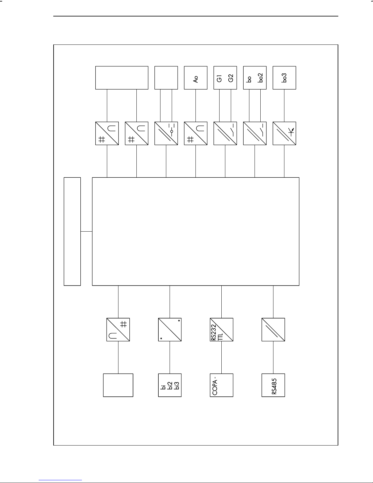
2.3.The process control station (overview)
Y1
4)
Y2
Y +
Y -
4)
4)
1
4)
4)
1
4)
Control elements
Control mode−Filtering, root extraction, func-
Software functions:
−
Ai 1
Ai 2
tion generation of input variables−Combination of input variables
Ai 3
Ai 4
(addition, subtraction, multiplica-
tion, calculation of mean value,
comparison, ratio)
Operation with two set points−Set point ramp and output
variable ramp
−
1
Optionally linear and non-linear
control algorithms and compen-
sation algorithms−Output signal limitation (fixed,
−
variable or by means of an input
variable)
Split-range operation−Definition of starting and
−
1)
pen/
adapter
restart conditions, limit alarms
Adaptation of control parameters
or parameter control by an
external signal−Selection control (limiting control)
−
2)
3)
Optional equipment
4)
,
3)
,
2)
,
1)
Fig. 1 ⋅ Block diagram of the process control station
7
Page 8
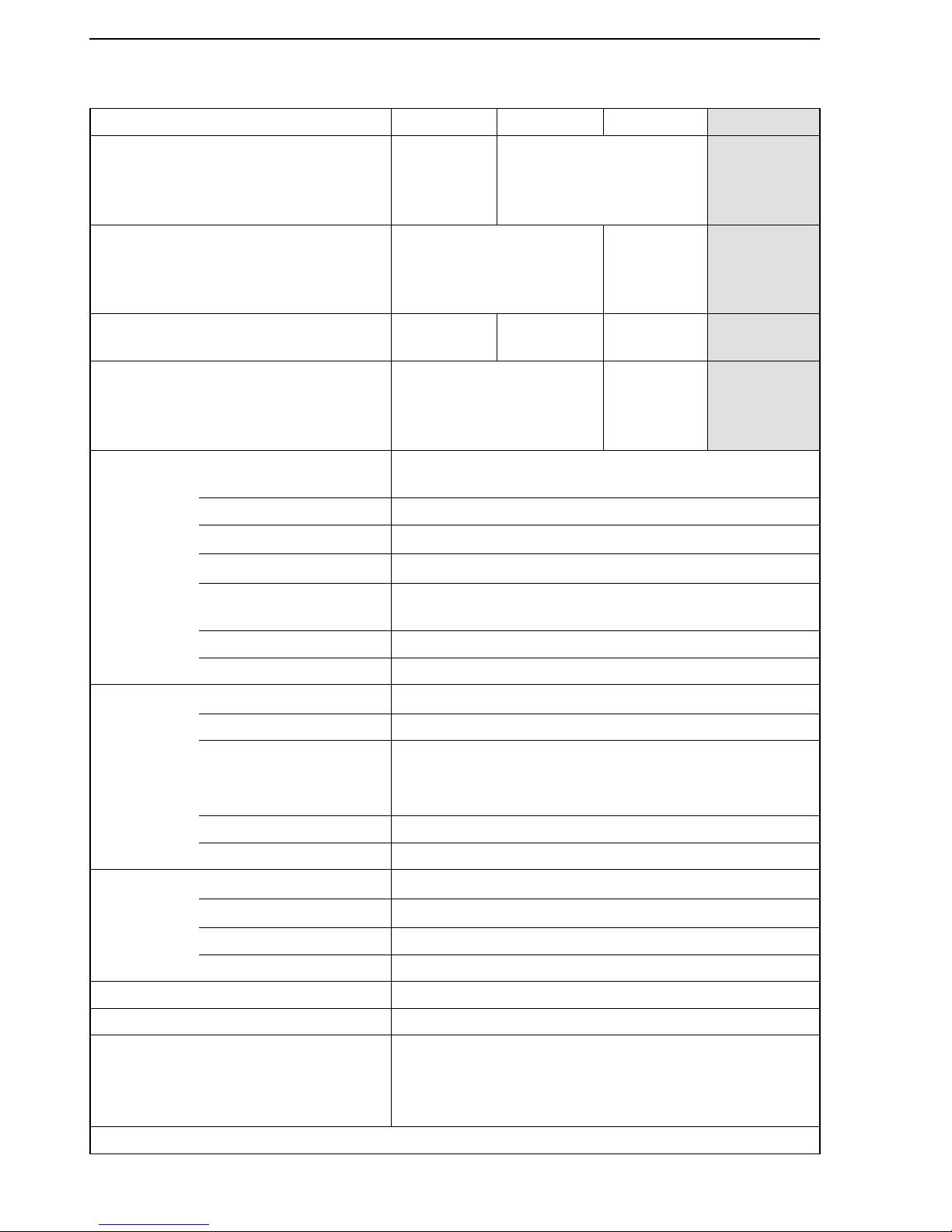
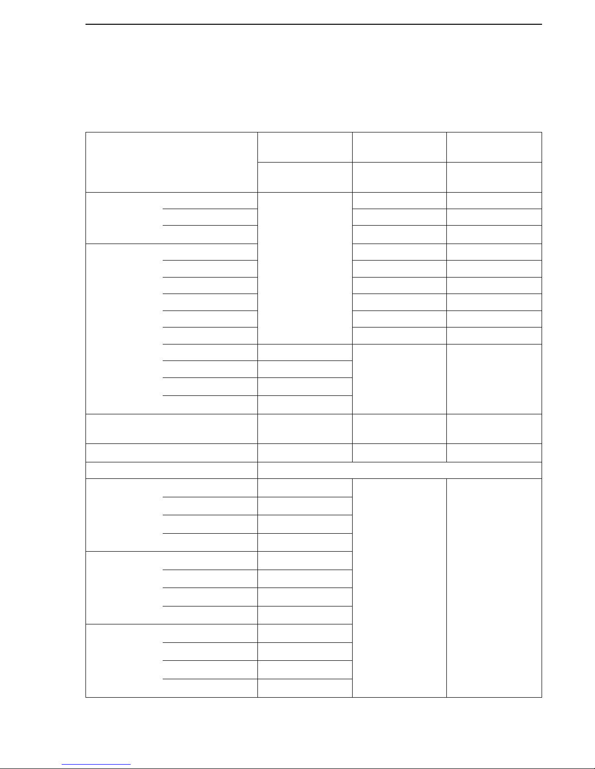
2.4.Technical data
Inputs
Input board 1 2 3 4
1)
Input 1 mA, V,
potentiometer,
transmitter
supply
Pt 100 in 2/3 or 4-wire
circuit
Thermocouple
(int./ext.
reference
junction)
Input 2
mA, V input,
transmitter supply
Pt 100
in 2/3
or 4-wire
circuit
mA, V,
transmitter
supply
Input 3 mA or V
input
mA, V,
transm. supply
Omitted Omitted
Input 4
mA, V or potentiometer
mA, V,
potentiometer,
transmitter
supply
mA, V or
potentiometer
mA or V
input
Measuring ranges 4(0) to 20 mA or
2(0) to 10 V; 0.2(0) to 1 V; 1(0) to 5 V
Meas. range switch-over Soldering jumpers
Max. permissible values
Current ± 50 mA, voltage ± 25 V
Internal resistance
Current R
i
= 50 Ω; voltage Ri = 200 k
Ω
Permissible
DC voltage
0 to 10 V
Error Zero point < 0.2 %, span < 0.2 %, linearity < 0.2 %
Temperature influence Zero point < 0.1 %/10 K; span < 0.1 %/10 K
Pt 100
temperature
sensors
Measuring ranges
2)
−
50 to 100 °C; 0 to 200 °C; 100 to 600 °C
Meas. range switch-over Soldering jumpers and configuration
Line resistances
Two-wire R
L1
+ R
L2
< 10 Ω,
Three-wire R
L1
= RL2 = RL3 < 50 Ω,
Four-wire, each R
L
< 100
Ω
Error Zero point, gain, linearity < 0.2 %
Temperature influence Zero point < 0.2 %/10 K; span < 0.2 %/10 K
Potentiometer Measuring range
0 to 1kΩ, ± 100 Ω, three-wire
Line resistance
R
L
< 10 Ω each
Error Zero point < 0.2 %, gain < 0.2 %
Temperature influence Zero point < 0.1 %/10 K; gain < 0.2 %/10 K
Thermocouple
1)
Specifications on request
Transmitter supply 16 to 23 V, max. 50 mA, short-term short-circuit protected
Binary inputs 3 binary inputs,
switching contacts (load 36 V DC, approx. 3 mA) or
external switching voltage (24 V DC, ± 30 %,
maximum 6 mA), selection via soldering jumpers
Technical data Description
8
Page 9

Description Technical data
Outputs
Continuous
control output
Signal range
Output control range
4(0) to 20(22) mA, permissible load < 750 Ω or
2(0) to 10 V, permissible load > 3 kΩ
−10 to 110 %
Error Zero point < 0.3 %, nominal end value < 0.3 %,
linearity < 0.3 %
Temperature influence Zero point < 0.1 %/10 K; nominal end value < 0.1 %/10 K
Switching output 1 on-off or three-step output,
250 V AC (1A AC, cos ϕ = 1)
Binary output (BO 3) Electrically isolated transistor output,
U
= 3 V DC,U
min
= 42 V DC, I
max
= 30 mA DC
max
Options Control output 1 continuous control output for split-range operation;
signal range, output control range, error and temperature
influence same as first continuous control output (see above)
Analog output
4(0) to 20 mA, permissible load < 750 Ω or
2(0) to 10 V or −10 to 10 V, permissible load > 3kΩ
Error and temperature influence same as first continuous
control output (see above)
Limit relay 2 relays, floating contacts, maximum 250 V AC
(1 A AC, cos ϕ = 1) or maximum 250 V DC (0.1 A DC)
Binary outputs 2; floating contacts; maximum 42 V AC (0.1 A AC);
42 V DC (0.05 A DC)
Interfaces
Serial
interface
on the
front-panel
Communications protocol TROVIS 6482 SAMSON Protocol
Number of stations 1
RS-232 in conjunction w. SAMSON cable no. 1170-1141
Length of cable < 2 m
Transmittable data Configuration, parameters, input and output signals for
graphic display
COPA pen Read/write pen for transmitting the CONFIGURATION and
PARAMETER data to/from the process controls station via
the front-panel serial interface
Serial
interface
RS-485
(optional)
Communications protocol Modbus RTU 584
Data transmission Asynchronous, half duplex, 4-wire or 2-wire
Character format RTU (8 bit), 1 start bit, 8 data bits, 1(2) stop bit(s),
optional parity bit
Baud rate 300 to 19200 bit/s
Number of addressable
246
stations
Number of stations 32 (can be extended with repeater)
Length of cable and
transmitting medium
Transmittable data Configuration, parameters, operating state,
< 1200 m, with repeater maximum 4800 m, 4-wire (2
wires twisted, stranded in pairs, with static screen)
process variables, error messages
9
Page 10

General specifications
Displays Read-off angle Readable from all sides, high-contrast and lighted
Liquid Crystal Display (LCD)
Displays
3
1
⁄
2
-digit set point (reference variable) display and
3
1
⁄
2
-digit controlled variable display; bar graph displays
for deviation (i.e. error) and output variable; LED displays
for range exceeding, alarm messages when limits are
exceeded, manual operation, faults etc.;
parameter display (only in the PARAMETER level)
Configuration Permanently stored function blocks for fixed set point
control, follow-up control with or without internal/external
set point change-over, cascade control, synchro control,
ratio control, SPC control, limiting control, DDC backup
fixed set point control via binary contact
Power supply 230 V AC (200 to 250 V AC),
120 V AC (102 to 132 V AC),
24 V AC (21.5 to 26.5 V AC),
Option 24 V DC (19 to 34 V DC);
48 to 62 Hz
Power consumption Approx. 18 VA
Temperature range
0 to 50 °C (operation),
−
20 to 70 °C (shipping and storage)
Degree of
protection
Panel-mounting unit: Front IP 54, case IP 30,
terminals IP 00;
Rack-mounting unit: IP 00
Overvoltage category II
Degree of contamination 2
Conformance to European standards EN 61010, edition March 1994
Electrical
connection
Functional earthing Panel-mounting unit: On case w. Cu-flex. lead > 2.5 mm
2
Rack-mounting unit: Connector, Type F
(DIN 41 612), Cu-flex. lead > 2.5 mm
2
Power voltage and
process signals
Panel-mounting unit: Screw terminals 1.5 mm2;
Rack-mounting unit: Two connectors, Type F
(DIN 41 612), soldering or crimp types
Total delay time
3)
Approx. 100 ms
Resolution Input and output, approximately 11 bits
Dimensions See Fig. 3 and Fig. 4
Weight Panel-mounting unit, approx. 1.9 kg; rack-mounting unit, 1 kg
1)
The input board 4 (thermocouple at input 1) is no longer available
2)
Specific measuring ranges on request
3)
Depending on how many functions are configured
Technical data Description
10
Page 11
Installing the process control stations TROVIS 6412 (panel-mounting unit)
3.Installing the process control stations
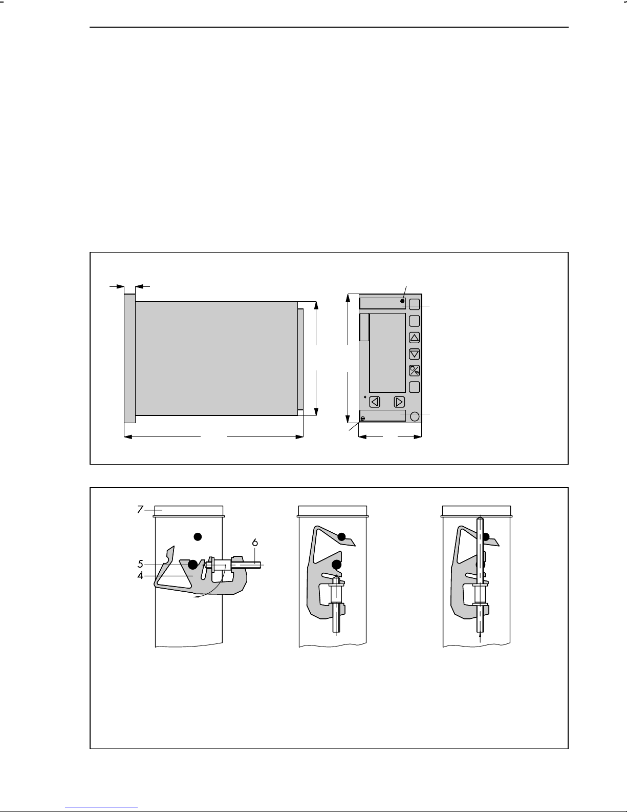
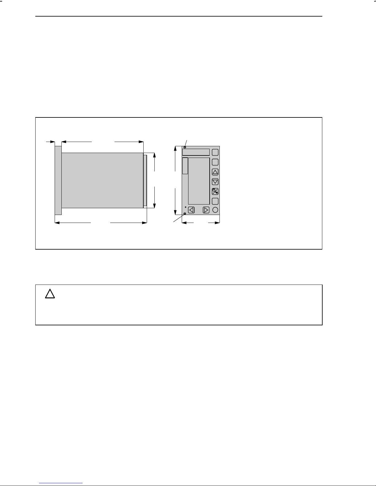
3.1.TROVIS 6412 (panel-mounting unit)
The TROVIS 6412 Process Control Station is designed for panel-mounting and has the front-frame
dimensions 72 x 144 mm. Perform the following steps in order to mount the controller:
1. Make a panel cut-out with the dimensions 68
+0.7
x 138
2. Push the process control station in the panel cut-out from the front side.
3. Install one supplied mounting bracket, both on the top and bottom of the control station
following steps 1) and 2) shown in Fig. 2 .
4. Turn the threaded rods in the direction of the control panel, using a screwdriver so that the
case is clamped against the panel ((step 3), Fig. 2 ).
16.5
(0.65)
+1.0
2
mm.
1
226
(8.90)
Fig. 3 ⋅ Dimensions (panel-mounting unit)
137.5
(5.41)
144
(5.67)
2
72
(2.83)
1
1 Label
2Screws
1) Insert on pin
(pivot) and turn
Fig. 2 ⋅ Installation (panel-mounting unit)
2) Click into
place
3) Screw tight
4 Mounting bracket
5Pin
6 Threaded rods
7 Front-panel bezel
11
Page 12
TROVIS 6442 (rack-mounting unit for 19inch racks) Installing the process control stations
3.2.TROVIS 6442 (rack-mounting unit for 19inch racks)
The TROVIS 6442 Process Control Station is a rack-mounting unit designed for mounting in
19inch racks. It has to be installed as follows:
1. Push the control station along the guiding rails into the corresponding rack unit, making
sure it does not become tilted. Push until the connectors connect.
2. Secure the process control station to the rack unit by fastening it from the front, using two
screws (see 1, Fig. 4 ).
3 Press one protective nipple (enclosed in the delivery) into each bore made for the screws.
14.5
(0.57)
Fig. 4 ⋅ Dimensions of the 19inch rack-mounting unit
162.5
(6.40)
190
(7.48)
100
(3.94)
128.5
(5.06)
1
1
70.5
(14 HP)
(2.77)
1Screw with
protective nipple
3.3.Opening the controller case
ATTENTION!
!
The case may only be opened by experienced personnel when the power to the process
control station has been cut off!
Re-jumpering (see section 4.) or retrofitting the process control station with an interface board
requires that the case be opened as follows:
1. With panel-mounting cases, remove small paper labels (see 1, Fig. 3 ) if necessary. With
19inch rack-mounting units, remove the two protective nipples. Unscrew the two screws
located on the front-panel of the case (see Fig. 3 or Fig. 4 , depending on the type of
case).
2. Withdraw controller section towards the front. Then, proceed as described for the
respective PCB to be modified.
12
Page 13

Installing the process control stations Opening the controller case
Modify input (5, Fig. 5 ) or/ and interface board (6, Fig. 5 ):
3. Unscrew the four screws (1, 2) and remove the two distance bolts (4).
4. Carefully withdraw the input and/or interface board from the case.
5. Modify the board as desired (see sections 4.1., 4.4.).
6. Carefully reinstall the interface or/and input board by plugging it/them into the associated
connectors. Make sure the connections are made correctly! Terminals 1 and 21 of each
connector are marked.
7. Reinstall the two distance bolts (3) and the four screws (1, 2).
Proceed as described under 8. to 10.
Modify the logic board (7, Fig. 5 ) as follows:
3. Unscrew the two screws (1).
4. Remove cover plate (3).
5. Modify the board as desired (s. sections 4.2. and 4.3.).
6. Reinstall cover plate, making sure that its curved part bends towards the outside.
7. Reinstall the two screws (1).
Proceed as described under 8. to 10.
8. Record any modifications made on the label located on the cover plate. With panel-mounting units, additionally mark modifications on the label on the outside case wall!
9. Insert controller section and fasten it with the two associated screws.
10. If necessary, reinsert small labels and protective nipple on the front-panel of the control
station.
4
4
2
1
1Screws
2Screws
3 Cover plates
4 Distance bolts
5Input board
6Interface board
7Logic board
8 Power supply board
9 Case section (only
panel-mount. unit)
Fig. 5 ⋅ Location of the boards in the controller case
13
Page 14
Determining the input signals Soldering jumpers
4.Soldering jumpers
ATTENTION!
!
The soldering jumpers may only be modified by experienced personnel when the power
to the process control station has been cut off!
Several functions of the process control station are determined by means of soldering jumpers.
Open the case as described in section 3.3. to modify the jumpers. The soldering jumpers are
marked on the soldering sides of the PCBs.
4.1.Determining the input signals
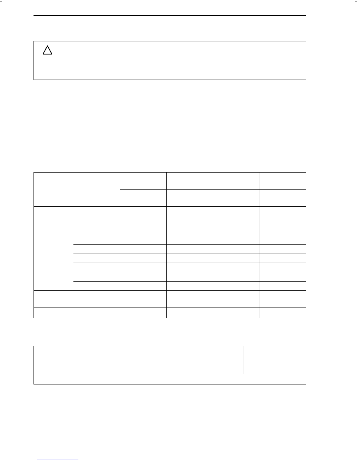
4.1.1.Input board 1 (IB1)
Note: Select the desired input signal and close the related soldering jumpers listed in line 3 or the following
ones of the table below (depending on type of signal selected)! Open all remaining jumpers associated with
the corresponding input (line 2)! See Fig. 5 for the location of the input board.
Input signal Input 1
(Ai 1)
Jumpers:
10 to 19
Current 0 to 20 mA 11 21 31 41, 45
4 to 20 mA 11, 14 21, 24 31, 34 41, 44, 45
−20 to 20 mA
Voltage 0 to 1 V11213141
0 to 5 V 12 22 32 42
0 to 10 V 13 23 33 43
0.2 to 1 V 11, 14 21, 24 31, 34 41, 44
1 to 5 V 12, 14 22, 24 32, 34 42, 44
2 to 10 V 13, 14 23, 24 33, 34 43, 44
Potentiometer
0 to 1kΩ
11, 15, 16 21, 25, 26
12, 17, 18
Input 2
(Ai 2)
Jumpers:
20 to 26
−−
Input 3
(Ai 3)
Jumpers:
31 to 34
−−
Input 4
(Ai 4)
Jumpers:
41 to 47
42, 46, 47
Transmitter supply 10, 11, 14, 19
Soldering jumpers associated with the binary inputs for all input boards:
Switching contact 50, 51 60, 61 70, 71
External switching voltage Jumpers mentioned above are open
14
Binary input 1 (bi 1)
Jumpers
20, 21, 24
Binary input 2 (bi 2)
Jumpers
−−
Binary input 3 (bi 3)
Jumpers
Page 15
Soldering jumpers Determining the input signals
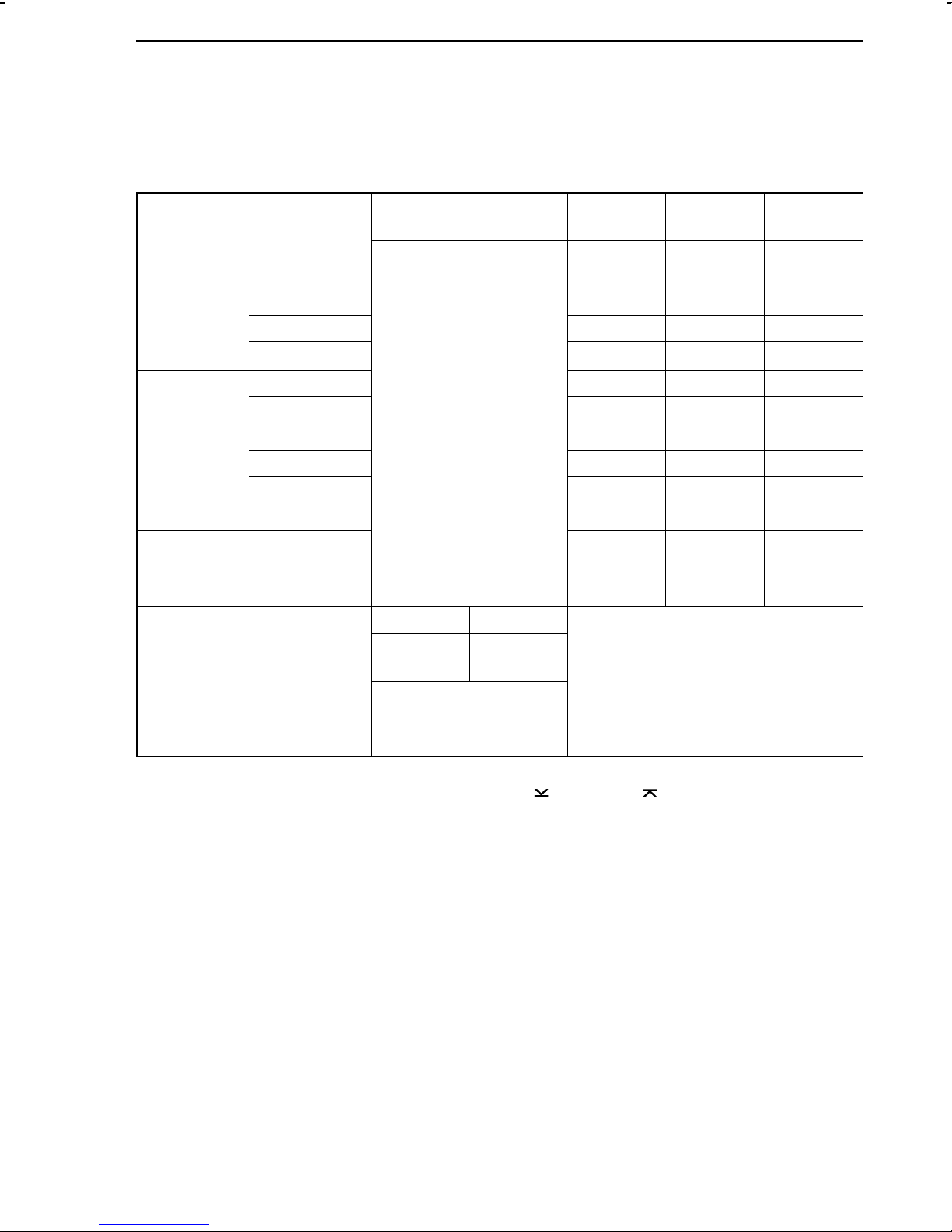
4.1.2.Input board 2 (IB 2)
Note: Select the desired input signal and close the related soldering jumpers listed in line 3 or the following
ones of the table below (depending on type of signal selected)! Open all remaining jumpers associated with
the corresponding input (line 2)! See Fig. 5 for the location of the input board. The soldering jumpers
associated with the binary inputs are described in section 4.1.1., page 14
Input signal Input 1
(Ai 1)
Input 2
(Ai 2)
Input 3
(Ai 3)
Input 4
(Ai 4)
Jumpers:
10 to 19
Current 0 to 20 mA
Jumpers:
20 to 26
Jumpers:
30 to 34
Jumpers:
41 to 47
21 31 41, 45
4 to 20 mA 21, 24 31, 34 41, 44, 45
−20 to 20 mA
21, 25, 26
−−
Voltage 0 to 1 V 213141
0 to 5 V 22 32 42
0 to 10 V 23 33 43
−
0.2 to 1 V 21, 24 31, 34 41, 44
1 to 5 V 22, 24 32, 34 42, 44
2 to 10 V 23, 24 33, 34 43, 44
Potentiometer
Transmitter supply
0 to 1kΩ−−
20, 21, 24
30, 31, 34
42, 46, 47
−
Pt 100 2 /3-wire 4-wire
10, 12, 13,
2)
15, X
Measuring
ranges
1)
−50 to 100 °C
0 to 200 °C
100 to 600 °C
1)
Select one measuring range and the corresponding soldering jumper. In the PA level, adjust the
measuring range by means of the parameters GWK
2)
For specific measuring ranges (on request), soldering jumper X must be open and soldering jum-
11, 14, 16,
2)
X
1)
19
1)
18
1)
17
and GWK1 .
1
−
per 17 must be closed.
15
Page 16
Determining the input signals Soldering jumpers
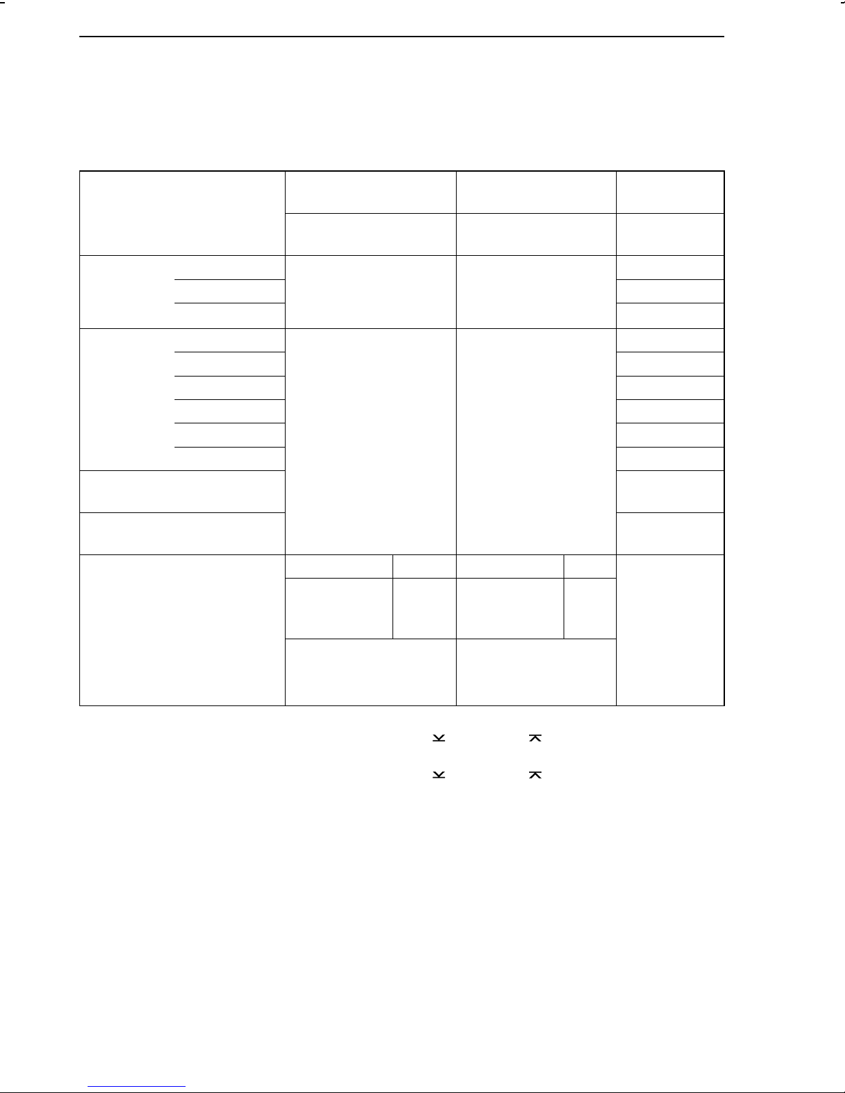
4.1.3.Input board 3 (IB 3)
Note: Select the desired input signal and close the related soldering jumpers listed in line 3 or the following
ones of the table below (depending on type of signal selected)! Open all remaining jumpers associated with
the corresponding input (line 2)! See Fig. 5 for the location of the input board. The soldering jumpers
associated with the binary inputs are described in section 4.1.1., page 14.
Input signal Input 1
(Ai 1)
Input 2
(Ai 2)
Input 4
(Ai 4)
Current 0 to 20 mA
4 to 20 mA 41, 44, 45
Jumpers:
10 to 19
−−
Jumpers:
20 to 29
Jumpers:
41 to 47
41, 45
−20 to 20 mA −
Voltage 0 to 1 V 41
0 to 5 V 42
0 to 10 V 43
0.2 to 1 V 41, 44
1 to 5 V 42, 44
2 to 10 V 43, 44
Potentiometer
0 to 1kΩ
42, 46, 47
Transmitter supply 40, 41, 44,
45, 48
Pt 100 2 /3-wire 4-wire 2 /3-wire 4-wire
10, 12, 13,
3)
15, X
Measuring
ranges
−50 to 100 °C
0 to 200 °C
100 to 600 °C
1)
Select one measuring range and the corresponding soldering jumper. In the Pa level, adjust the
measuring range by means of the parameters GWK
2)
Select one measuring range and the corresponding soldering jumper. In the PA level, adjust the
measuring range by means of the parameters GWK
3)
For specific measuring ranges (on request), soldering jumper X must be open and soldering jum-
19
18
17
1)
1)
1)
11, 14,
16, X
1
2
20, 22, 23,
3)
25, XX
and GWK1 .
and GWK2 .
21,24,
4)
29
28
27
26,
4)
XX
2)
2)
2)
−
per 17 must be closed.
4)
For specific measuring ranges (on request), soldering jumper XX must be open and soldering jumper 27 must be closed.
16
Page 17
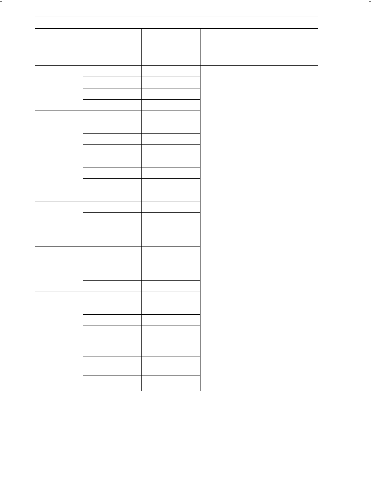
4.1.4.Input board 4 (IB 4)
Input board 4 is no longer available.
Note: Select the desired input signal and close the related soldering jumpers listed in line 3 or the following
ones of the table below (depending on type of signal selected)! Open all remaining jumpers associated with
the corresponding input (line 2). See Fig. 5 for the location of the input board. The soldering jumpers
associated with the binary inputs are described in section 4.1.1., page 14.
Input signal
Input 1
(Ai 1)
Input 2
(Ai 2)
Input 3/4
(Ai 3/4)
Jumpers:
10 to 19
Jumpers:
20 to 26
Jumpers:
41 to 47
Current 0 to 20 mA
−
21 41, 45
4 to 20 mA 21, 24 41, 44, 45
−
20 to 20 mA
21, 25, 26
−
Voltage 0 to 1 V 21 41
0 to 5 V 22 42
0 to 10 V 23 43
0.2 to 1 V 21, 24 41, 44
1 to 5 V 22, 24 42, 44
2 to 10 V 23, 24 43, 44
0 to 50 mV 17
−−
0 to 100 mV 16
−
50 to 50 mV
15
−
100 to 100 mV
14
Potentiometer
0 to 1k
Ω− −
42, 46, 47
Transmitter supply
−
20, 21, 24, 29
40, 41, 44, 45, 49
Thermocouples
Type U
0 to 200 °C
17
−−
150 to 400 °C
16
300 to 600 °C
15
0 to 600 °C
14
Type R
0 to 700 °C
17
500 to 1200 °C
16
1000 to 1700 °C
15
0 to 1700 °C
14
Type T
0 to 150 °C
17
100 to 250 °C
16
200 to 400 °C
15
0 to 400 °C
14
Soldering jumpers Determining the input signals
17
Page 18
Determining the input signals Soldering jumpers
Input signal Input 1
(Ai 1)
Jumpers:
10 to 19
Type S
Type L
Type B
Type J
0 to 700 °C
500 to 1200 °C
1000 to 1700 °C
0 to 1700 °C
0 to 350 °C
250 to 600 °C
500 to 900 °C
0 to 900 °C
200 to 1200 °C
1000 to 1500 °C
1300 to 1800 °C
200 to 1800 °C
0 to 400 °C
350 to 800 °C
17
16
15
14
17
16
15
14
17
16
15
14
17
16
Input 2
(Ai 2)
Jumpers:
20 to 26
Input 3/4
(Ai 3/4)
Jumpers:
41 to 47
−−
Type E
Type K
Reference
junction
temperature
for external
reference
junction
700 to 1200 °C
0 to 1200 °C
0 to 400 °C
300 to 700 °C
600 to 1000 °C
0 to 1000 °C
0 to 500
°C
400 to 900 °C
800 to 1300 °C
0 to 1300 °C
0 °C
20 °C
50 °C
15
14
17
16
15
14
17
16
15
14
11
12
13
18
Page 19
Soldering jumpers Soldering jumpers on the logic board
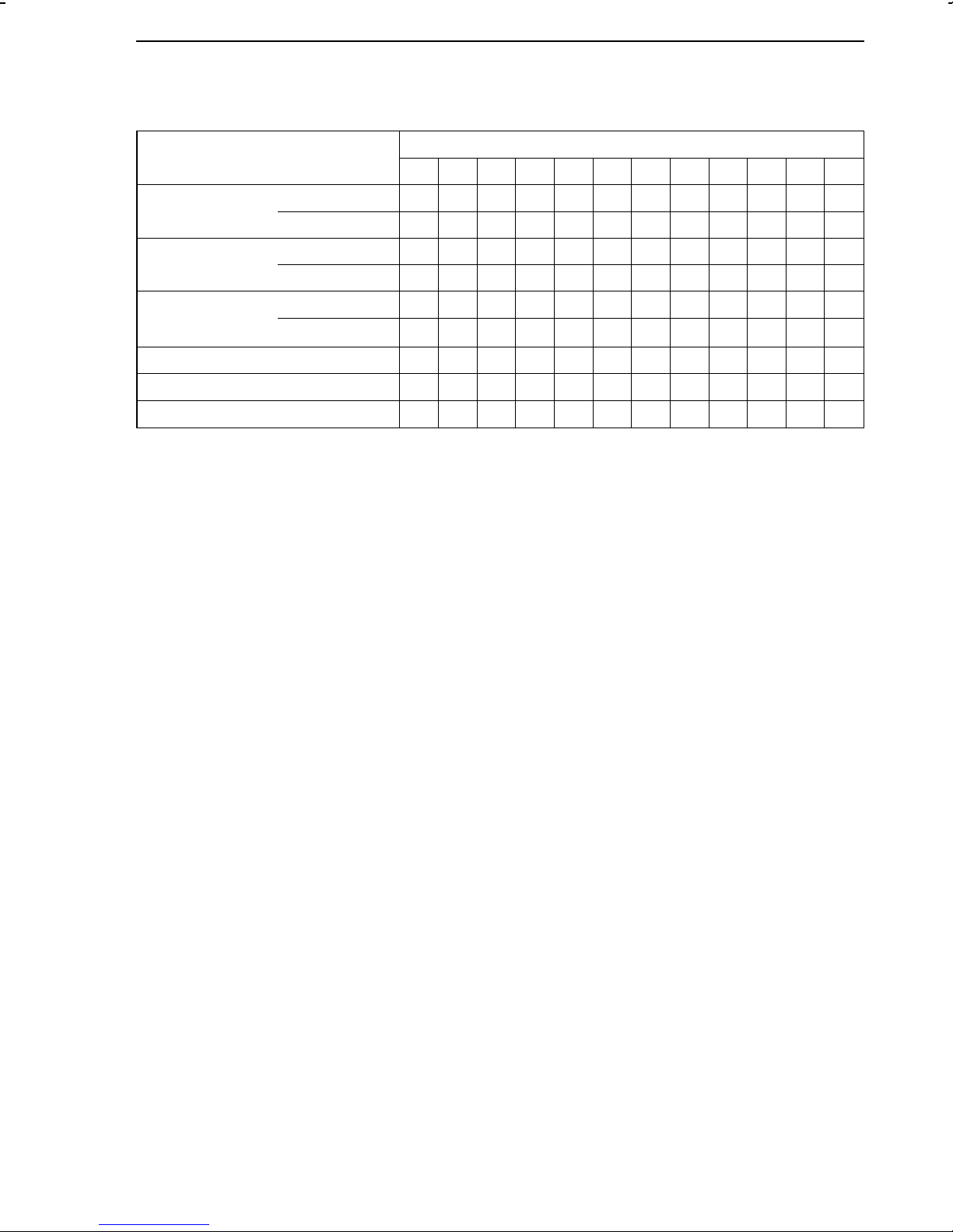
4.2.Soldering jumpers on the logic board
See Fig. 5 for the location of the logic board
Soldering jumper: X closed, 0 open
11 13 21 23 31 33 37 38 SZ LB 1 LB 2 LB 3
Continuous
control output Y1
Continuous
control output Y2
Analog output
Ao1
Operation with code number X
Operation with interface X X X
0(4) to 20 mA X 0
0(2) to 10 V 0 X
0(4) to 20 mA X 0
0(2) to 10 V 0 X
0(4) to 20 mA X 0 X 0
−10 to 10 V
0(2) to 10 V 0 X X 0
0X0X
4.3.Soldering jumper for implementing the code number
The CONFIGURATION level and the PARAMETER level can be protected against unauthorized
use by means of code numbers. To activate this function, the soldering jumper SZ located on
the logic board must be closed (see table in section 4.2.). This jumper SZ is open when the
controller is delivered, meaning that the configuration and parameter data of the process
control station can be modified without having to enter a corresponding code number.
Refer to section 6.10 and 6.11 on how to define the code numbers for CONFIGURATION level
and the PARAMETER level.
19
Page 20

Soldering jumpers on the interface board Soldering jumpers
4.4.Soldering jumpers on the interface board
See. Fig. 5 for the location of the interface board and Fig. 6 for the location of the soldering
jumpers.
Important! In the interface mode, the soldering jumpers LB1, LB2 and LB3 on the logic board
must also be closed (see section 4.2., page 19). This must be observed when retrofitting the
process control station with the interface board.
Soldering jumper (LB) Default setting:
X closed, 0 open
Enable parity bit PARITAET 0
Parity odd UNGERADE 0
2 stop bits RES 0
Baud rate Modbus Select a soldering jumper
300 bit/s 300 0
600 bit/s 600 0
1200 bit/s 1200 0
2400 bit/s 2400 0
4800 bit/s 4800 0
9600 bit/s 9600 X
19200 bit/s 19200 0
Termination BUSABSCHLUSS (4 LBs) 0
Two-wire mode 2LEITER (2 LBs) 0
Four-wire mode 4LEITER (2 LBs) X
20
Page 21
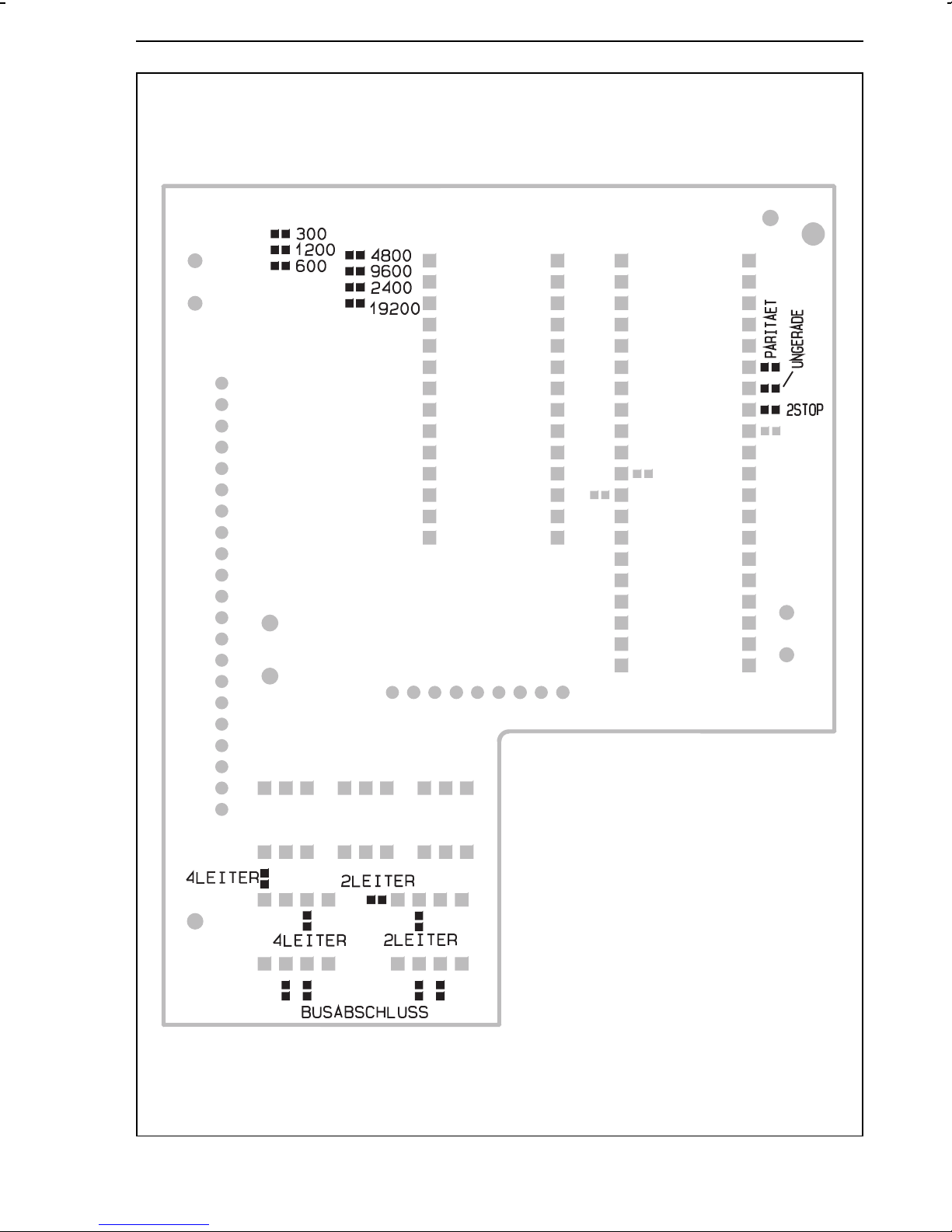
Soldering jumpers Soldering jumpers on the interface board
Fig. 6 ⋅ Location of the soldering jumpers on the interface board
21
Page 22
TROVIS 6412 (panel-mounting unit) Electrical connections
5.Electrical connections
When making the electrical connections, note the VDE 0100 regulations and the regulations
valid in the country where the control station is intended to be installed.
Use shielded cables for the signal lines of the analog and binary inputs, which are installed
outside the control cabinets, in order to avoid measuring errors or other interferences. Inside
the control cabinets, these lines have to be installed separately from the control and power
supply lines.
The shieldings of the lines are to be grounded on one side at the neutral point of the measuring
and control system.
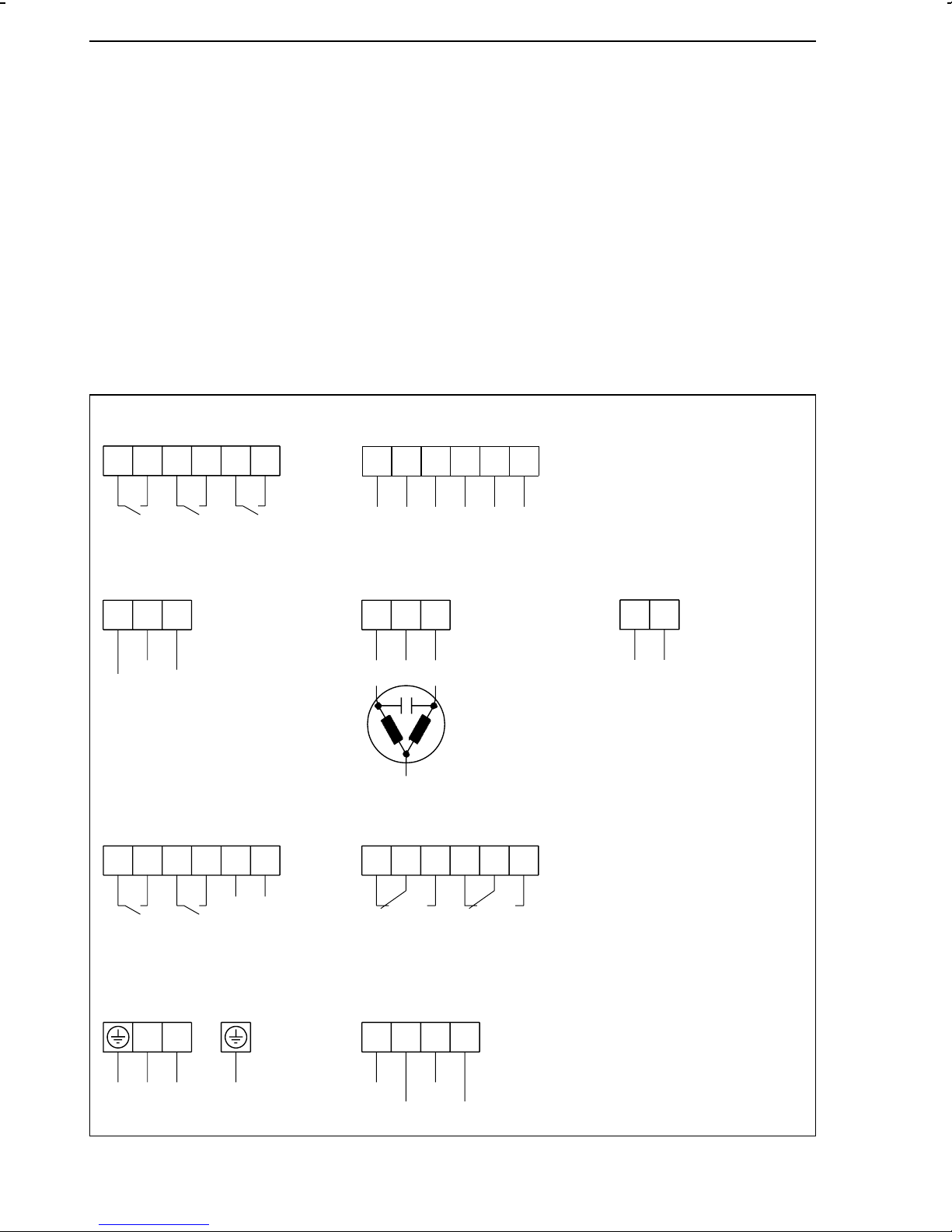
5.1.TROVIS 6412 (panel-mounting unit)
The device has plug-in terminals for wires with cross-sections of 0.5 to 1.5 mm2 (DIN 45 140).
Binary inputs
Switching contact External switching voltage
81 82
bi 1
83
bi 2
84
85
bi 3
86
81 82
+
bi 1
83
84
+
–
–
bi 2
85
+
86
–
bi 3
Continuous control outputs Switching output Analog output
33
32
31
0
Y2
1)
Y1
Binary outputs Limit relay
88 89
87
1)
bo 1
bo 2
90
91
92
+
1)
–
bo 3
47 48
–
41
49
+
L1
N
1)
43
42
G1 G2
51
52
53
34 35
–
Ao 1
1),2)
1)
+
Optional equipment
Power supply Serial interface RS-485
N
L
Fig. 7 ⋅ Terminal assignment of TROVIS 6412
22
96
T(A)
97
T(B)
98
R(B)
99
R(A)
2)
For 2-wire bus
Terminals 96 and 97
Page 23
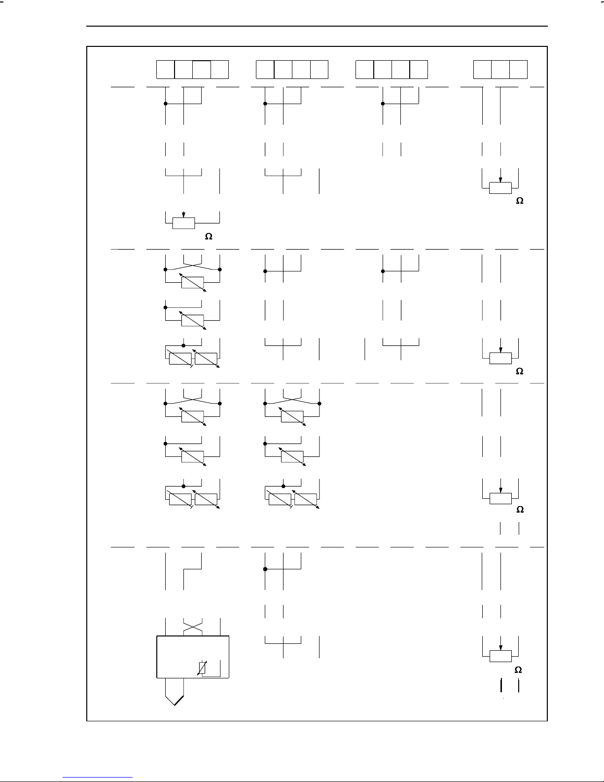
Electrical connections TROVIS 6412 (panel-mounting unit)
Inputs
Input
board 1
(IB 1)
Input
board 2
(IB 2)
Ai 1
–
mA
–
V
+
0...1000
13 14
15
16
+
mA
+
V
–
+
mA
+
V
11 12
+
+
2-wire transmitter 2-wire transmitter
4W
3W
Ai 2
–
+
–
–
Ai 3
18
18
17
–
–
19
+
+
+
+
mA
V
mA
V
20
21
–
–
0%
–
–
Ai 4
23
24
+
mA
+
V
0...1000
+
mA
+
V
25
–
–
–
–
Input
board 3
(IB 3)
Input
board 4
(IB 4)
With reference
junction sensor
(item no.
1070-8472)
2W
4W
3W
2W
+
Ri
Ri
–
mV source
1
2
8
7
Pt 100
Pt 100
34
+
2-wire transmitter 2-wire transmitter
Ri
+
–
mA
+
–
V
+
2-wire transmitter
–
Pt 100
–
–
+
2-wire transmitter
0%
0%
0%
0...1000
+
mA
+
V
0...1000
+
mA
+
V
0...1000
–
–
+
–
–
–
–
+
Fig. 8 ⋅ Terminal assignment of TROVIS 6412 (continued)
2-wire transmitter + −
+
–
23
Page 24
TROVIS 6442 (rack-mounting unit for 19inch racks) Electrical connections
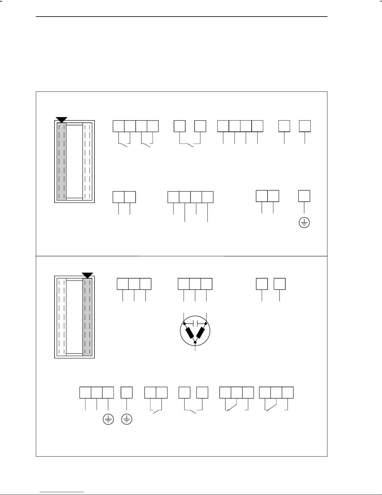
5.2.TROVIS 6442 (rack-mounting unit for 19inch racks)
The device has two plug connectors, style F (DIN 41612). The signal lines are assigned to one
of these two connectors, whereas the power supply lines are assigned to the other one, meaning
these lines are installed separately (see Fig. 9 and Fig. 10 ).
Binary inputs
Switching contact External switching voltage
d
4
2
6
8
d
10
z
16
d
4
2
6
8
d
10
z
16
bi1
bi2
bi3
+
Binary output 3 Serial interface RS-485
d
30
+
32
–
bo3
d
26
28
R(B)
R(A)
For 2-wire bus terminals
d 22 and d 24
24
T(A)
22
T(B)
bi1
2)
–
–
+
bi2
dd
18
00
+
16
Continuous control outputs Switching output Analog output
d
14 16
1)
Y1
Y2
18
–
z
810
+
L1
12
d
z
16
18
–
+
–
Ao 1
–
bi3
12
1)
Power supply Binary outputs
z
24
N
d
6
6
FE
Fig. 9 ⋅ Terminal assignment of TROVIS 6442
24
N
1)
Limit relay
zd
28
30
bo1
32
z
32
bo2
d
24 26 28
G1 G2L
1)
z
20 22 24
Page 25
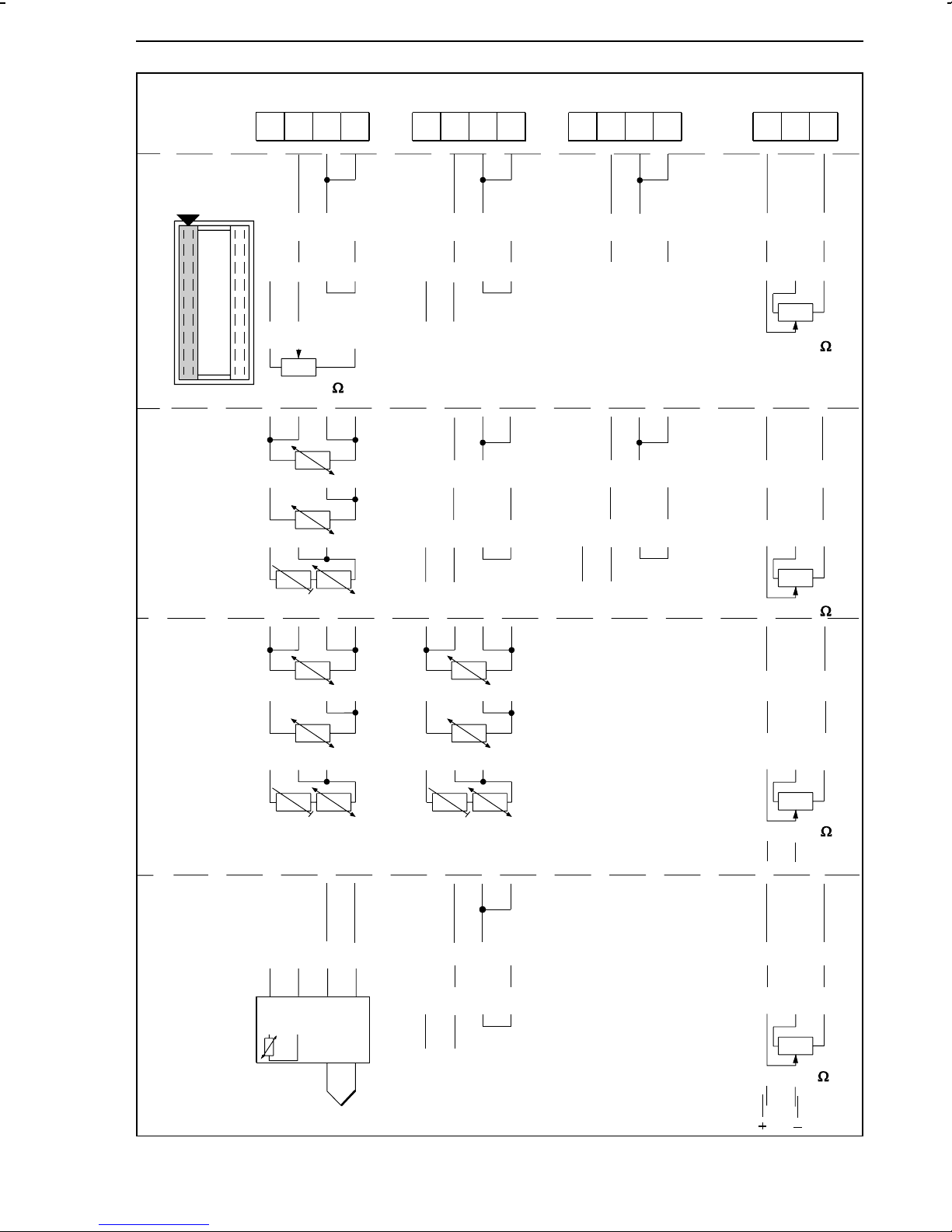
Electrical connections TROVIS 6442 (rack-mounting unit for 19inch racks)
Inputs
Input
board 1 (IB 1)
Input
4W
board 2
(IB 2)
3W
Ai 1
z
–
mA
–
+
0...1000
28 26
+
V
+
32 30
–
2-wire transmitter 2-wire transmitter
z
24
Ai 2
20
22
+
–
mA
–
V
+
–
+
–
mA
–
V
18
Ai 3
z
24
14
–
+
+
–
–
–
mA
mA
12
V
V
10
+
+
+
+
Ai 4
z
6
–
–
0...1000
–
mA
–
4
2
+
+
0%
+
+
V
Input
board 3
(IB 3)
Input
board 4
(IB 4)
With reference
junction sensor
(item no.
1070-8472)
2W
4W
3W
2W
1
Ri
Ri
Pt 100
Pt 100
–
mV source
34
2
7
–
+
–
2-wire transmitter 2-wire transmitter
Pt 100
Ri
+
8
+
–
2-wire transmitter
+
–
mA
–
+
+
V
+
–
2-wire transmitter
2-wi re transmit te r
0...1000
–
–
0...1000
+
–
–
0...1000
+
0%
+
mA
+
V
0%
–
+
mA
+
V
0%
–
Fig. 10 ⋅ Terminal assignment of TROVIS 6442 (continued)
25
Page 26

Balancing the line resistance for the connection of Pt 100 sensors Electrical connections
5.3.Balancing the line resistance for the connection of Pt 100 sensors
When Pt 100 sensors are connected to the control station in a two-wire circuit, the line
resistance is to be balanced to 10 Ω at the external resistor Rj in order to avoid measuring
errors:
1. Short-circuit the line at the Pt 100 sensor or potentiometer.
2. Switch the resistor R
in the line.
j
3. Measure the resistance in the total circuit, using a suitable ohmmeter.
4. Adjust the resistor R
until the line resistance is 10 Ω.
j
In three-wire circuits, the line resistance must not be balanced. Zero and span, however, should
be checked and re-adjusted if necessary.
In four-wire circuits, balancing the line resistance is also not necessary.
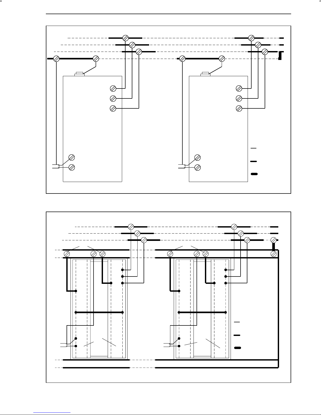
5.4.Wiring technique with regard to electromagnetic compatibility
All input, output and data lines have to be run in shielded cables for reasons of electromagnetic
compatibility (EMC).
The power supply lines, as well as the protective conductors and the functional earthing line
(FE) are to be connected separately from each controller to the corresponding multi-terminal
bus bar.
With 19inch racks, a conductive connection between the functional earthing line and the rack
has to be made.
The shielded cables are to be grounded at one end (see Fig. 11 and Fig. 12 ).
26
Page 27
Electrical connections Wiring technique with regard to electromagnetic compatibility
L
N
PE
FE
L
N
PE
Controller 1 Controller n
Fig. 11 ⋅ Electrical connections for panel-mounting units
FE
N
L
PE
Cu-flex. lead
≥ 1.5 mm
Cu-flex. lead
≥ 2.5 mm
Cu-flex. lead
≥ 10 mm
2
2
2
FE
d12
d18
z2
z4
d6
z6
d18
2
1
FE
d12
d18
z2
z4
z6
d6
d18
2
1
Controller 1 Controller n
1Plug connector
Signal lines
2Plug connector
Control lines
Cu-flex. lead
≥ 1.5 mm
Cu-flex. lead
≥ 2.5 mm
Cu-flex lead
≥ 10 mm
2
2
2
L
N
PE
Fig. 12 ⋅ Electrical connections for 19inch rack-mounting units
27
Page 28

Process display and control panel elements Operation
6.Operation
This section describes how to operate the process control stations directly on the control panel.
Unfold the last page of this manual to obtain a better understanding of this description!
The process control stations are designed according to a three-level, logic operating structure:
1) OPERATING level, 2) PARAMETER level and 3) CONFIGURATION level. These levels are
described in sections 6.2. to 6.13. Depending on the selected level (mode), the visual displays
on the LCD panel and the keys assume different functions.
6.1.Process display and control panel elements
The process control station is operated via eight front-panel keys. The front panel also contains
a clear display field, which shows different variables and symbols, depending on the selected
operating level. Note that some parameters available in the PARAMETER and ADAPTATION
PARAMETER level can be a combination of several variables and symbols.
All process display and control panel elements are listed and explained on the last two pages
of this manual. Optional error messages are described in Appendix B .
6.2.OPERATING level
This is the standard operating level of the process control station (control mode). In this level,
the control station operates according to the pre-set control mode and the defined parameters.
The values of the set point (reference variable) (3) and the controlled variable (8) are
numerically indicated on the display panel. The control deviation (error) (7) and the output
variable (14) are represented as a percentage by means of bar graphs. In addition, a LED (19)
indicates whether the control station is in the AUTOMATIC or MANUAL mode. If the F key is
pressed, the numerical value of the output variable appears in the upper line of the display field
(3).
The OPERATING level allows the operator to modify the value of the internal set point (reference
variable), abort the restart condition option after a start-up procedure or a power supply failure
has occurred, or open the cascade when the controller is in the follow-up control mode. The
output variable can be modified manually when having changed over the process control
station to the MANUAL mode. These functions are described in the following sections.
All other levels can be accessed from the OPERATING level.
28
Page 29
Operation OPERATING level
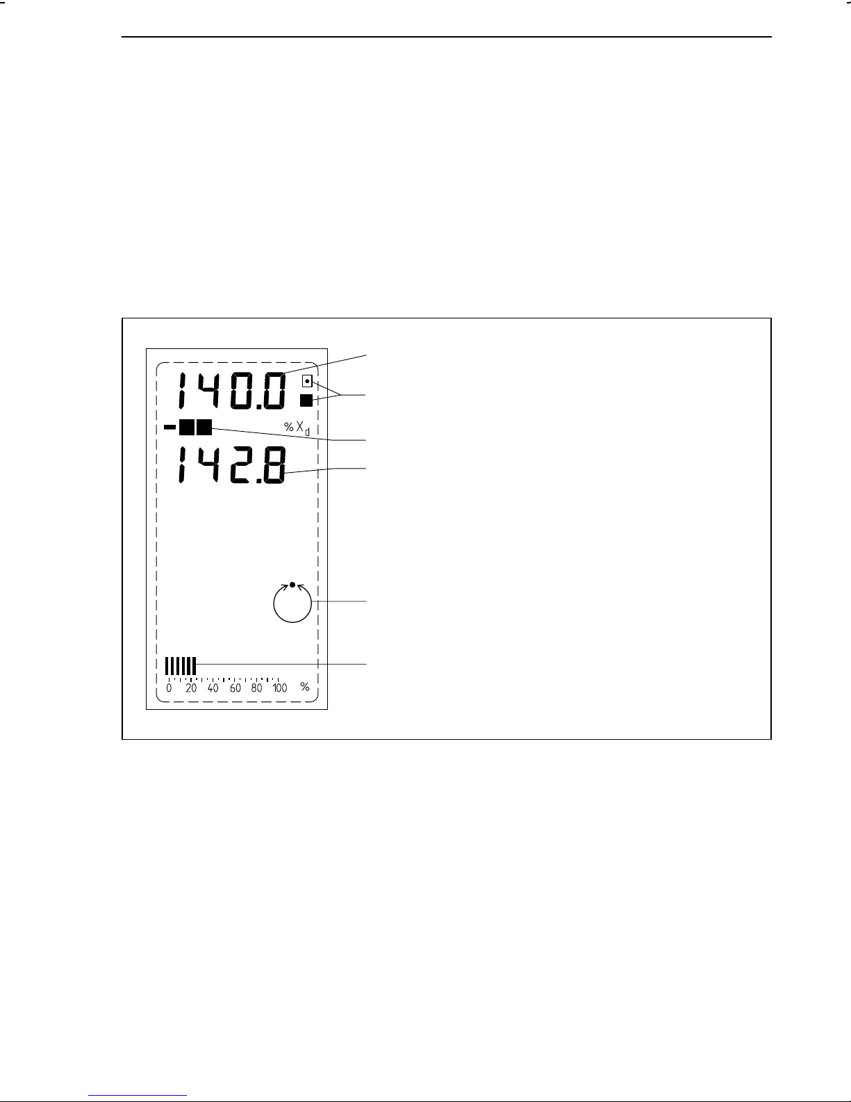
6.2.1.Modifying the internal set point (reference variable)
In the OPERATING level, the internal set point WIN can be modified by pressing the C or D key,
provided that these keys have not been disabled in the CONFIGURATION level (C59-2 or
C59-4). Pressing the respective key briefly modifies the last digit of the indicated number by
one. The key must be held down to further advance the number. In this case, the displayed value
changes more quickly. While this modification is made, W
display. W
be configured to display other values than W
disappears after approximately 3 s. Note that the digital display field (3) can also
IN
(see configuration block C4).
IN
Pressing the C key increases the set point (reference variable).
Pressing the D key decreases the set point (reference variable).
3
16
is additionally indicated on the
IN
7
8
19
14
Fig. 13 ⋅ Display of the set point (reference variable) in the OPERATING level
3 Set point (reference variable)
7 Control deviation (error)
8 Controlled variable
14 Manipulated variable display
16 Indicator "internal set point valid"
19 AUTOMATIC mode
29
Page 30
OPERATING level Operation
6.2.2.Power supply failure
Configuration block C 43 (restart condition) defines the behaviour of the process control station
after switching on the power supply in the start-up phase or after detecting a power supply
failure (> approx. 1 s). This restart condition determines the operating mode, the set point
(reference variable) and the output variable for output Y1 or Y2.
If one of the restart conditions C43-1 to C43-6 is set, it is necessary to confirm the setting by
pressing the F key in order to return to the normal control mode. In both cases, the digital
displays for the set point and the controlled variable flash until the F key is pressed. The settings
C43-5 and C43-6 cause the process control station to remain in the MANUAL mode, even when
the F key is pressed. This is indicated by the symbol in (19).
The settings C43-7 to C43-12 must not be confirmed in order to return to the normal control
mode. The process control station automatically operates in the control mode according to the
restart conditions implemented with configuration block C 43.
The following table is a short summary of the optional restart conditions.
C43 Set point Output variable Oper. mode Press F-key Comment
-1, -2 Last active Y
-3, -4 W
-5, -6 Last active Y1K1, Y2K
-7, -8 Last active Y
-9, -10 Internal Y
-11, -12 External Y
S
, Y2K
1K1
Y1K1, Y2K
, Y2K
1K1
, Y2K
1K1
, Y2K
1K1
1
1
1
1
1
1
Automatic Yes
Automatic Yes WS overwrites W
Manual Yes
Automatic No
Automatic No
Automatic No
After pressing F,
still MANUAL mode
IN
6.2.3.Manual adjustment of the output variable
In MANUAL mode, the connected control valve can be manually moved to the desired position,
using the G and H keys, provided that these keys have not been disabled in the configuration
mode (C59-2 or C59-4). The corresponding key must be pressed until the desired output
variable is adjusted. The bar graph (13) indicates the change in the output variable. If the F key
is pressed, the numerical value of the output variable is also displayed in the digital display
field (2).
Bumpless change-over from MANUAL to AUTOMATIC mode and vice versa is carried out via
the MANUAL/AUTOMATIC key (E).
Pressing the G key increases the output variable.
Pressing the H key decreases the output variable.
30
Page 31

Page 32

PARAMETER level Operation
6.3.PARAMETER level
The control parameters can be displayed and modified in the PARAMETER level. When the
control station operates with a code number (code number mode) (see 4.3.), the parameters
can only be modified after having entered the valid code number.
Only parameters that are supported by the controller’s configuration can be displayed and
modified. All dynamic parameters (e.g.. X, W
, Z, XD, Y1, Y2), however, cannot be modified.
EX
6.3.1.Operating the PARAMETER level
See last page of this manual for the designations of the keys and displays! The process control
station is in the OPERATING level. Fig. 14 is a simplified representation of how to set a
parameter.
Accessing the PARAMETER level and displaying the parameter values
1. Press A key. I-O appears on the display.
2. Press C key. PA appears on the display.
3. Press A key. Now, the control station is in the parameter mode. The LCD panel additionally
shows the value of the currently selected parameter in the digital display field (3), the
control deviation (error) bar graph (7), the parameter table (21), and the bar graph
representing the output variable (14). The selected parameter flashes. When accessing the
PARAMETER level for the first time, the flashing parameter is always the one which was
selected last during a former modification process.
4. All parameters can be displayed by pressing the C or D key. Attention: the parameters can
be combinations of several symbols, e.g. Y
1K1
.
Modifying parameter values
1. Follow steps 1 to 3 listed under "Accessing the PARAMETER level and displaying the
parameter values".
2. Select the parameter to be modified by pressing the C or D key.
3. Press A key when the selected parameter flashes in the parameter table.
What comes up on the display now depends on whether the process control station
operates either with or without a code number.
If no code number was entered, PA flashes on the display. Hold down the A key for approx.
3 s. Continue as described under 4.
If a code number was entered, PA and flash on the display. Use the C and D keys to
set the code number in the upper line of the display (3). Then, press A key. Now the
parameter table should reappear on the display. If not, the wrong code number was
entered. Re-enter the code number, using the C and D keys or cancel by pressing the F key.
4. The selected parameter and PA flash on the display. Now a new parameter value can be
set by pressing the C and D keys. Then, press A key to accept.
5. Select next parameter with the C and D keys. Press A key, and modify them as described
under 4.
Exiting the PARAMETER level
1. Press F key.
The process control station returns to the OPERATING level.
32
Page 33

Operation PARAMETER level
Fig. 14 ⋅ Simplified parameter setting diagram
…
keys
33
Page 34

PARAMETER level Operation
6.3.2.Example how to modify a parameter
This section describes how to modify a parameter, using KP as an example. All other parameters
have to be modified accordingly.
Fig. 15
The process control station is in the standard
operating mode and the display is, for example as shown in Fig. 15 .
Fig. 16
Press A key. I-O comes up on the display.
Fig. 15 Fig. 16
Fig. 17 Fig. 18
Fig. 19 Fig. 20
Fig. 17
Press C key. PA appears on the display.
Fig. 18
Press A key. The LCD panel shows, for example this display. The parameter which was
changed last (here T
) flashes.
N
Fig. 19
Press C or D key several times until K
(only K
!). The valid KP value, here 1.8, is
P
flashes
P
displayed in the upper line of the display.
Fig. 20
Press A key.
If no code number was entered (factory default) PA flashes on the display. Hold down
the A key for approximately 3 s.
If a code number was entered (not shown in
this figure), PA and flash. Use C and D
keys to set the code number in the upper line
of the display (3). Then, press A key.
34
Page 35

Operation PARAMETER level
Fig. 21
K
and PA flash.
P
Enter new K
value by pressing the C and D
P
keys (in this example, 3.2).
Fig. 22
Press A key to accept.
The new K
Fig. 21 Fig. 22
value is stored. Only K
P
flashes.
P
Fig. 23
Press F key.
The process control station has returned to the
OPERATING level.
Fig. 23
35
Page 36

CONFIGURATION level Operation
6.4.CONFIGURATION level
The configuration blocks can be displayed and modified in the CONFIGURATION level. When
the control station operates with a code number (code number mode), the configuration blocks
can only be modified after having entered the valid code number. Configuration blocks
determine the control functions. These blocks and the associated functions are described in more
detail in Configuration manual KH 6412 E.
The configuration blocks are designated C1 to C59. The control mode selected determines
which configuration blocks are relevant. Only these blocks can be displayed and modified.
6.4.1.Operating the CONFIGURATION level
See last page of this manual for the designations of the keys and displays! Operation of this
CONFIGURATION level is described, starting from the OPERATING level. Fig. 24 is a simplified
representation of how to set a configuration block.
Accessing the CONFIGURATION level and displaying the configuration blocks
1. Press A key. I-O appears on the display.
2. Press C key several times until CO appears on the display.
3. Press A key. Now, the upper line of the display shows the setting of the configuration block
(e.g. - 1), and the associated designation of this block (e.g. C 1) is indicated in the lower
line of the display. When accessing the CONFIGURATION level for the first time, the
display always shows the configuration block which was viewed or modified last.
4. The individual configuration blocks can be viewed by pressing the C or D key.
Modifying configuration blocks
1. Follow steps 1 to 3 listed under "Accessing the CONFIGURATION level and displaying the
configuration blocks".
2. Select the configuration block to be modified by pressing the C or D key.
3. Press A key.
What comes up on the display now depends on whether the process control station
operates either with or without a code number.
If no code number was entered, CO flashes on the display. Hold down the A key for
approx. 3 s. Continue as described under 4.
If a code number was entered, CO and flash on the display. Use the C and D keys to
set the code number in the upper digital display field (3). Then, press A key. Should CO
and still flash on the display, the wrong code number was entered. Re-enter the code
number or exit the CONFIGURATION level as described below.
4. C and − flash on the display.
5. Select new value for the configuration block, using the C and D keys. Then, press A key to accept.
6. Select other configuration block with the C and D keys. Press A key. Continue as described
under 5. or exit the CONFIGURATION level.
Exiting the CONFIGURATION level
1. Press F key.
After having modified the configuration blocks, the control station returns to the OPERATING level and is in the MANUAL mode.
36
Page 37

Operation CONFIGURATION level
Fig. 24 ⋅ Simplified configuration diagram
…
keys
37
Page 38

CONFIGURATION level Operation
6.4.2.Example how to modify a configuration block
This section describes how to modify a configuration block, using C5 (configuration of controller
outputs) as an example. All other configuration blocks have to be modified accordingly.
Fig. 25
The process control station is in the standard
operating mode and the display is, for example as shown in Fig. 25 .
Fig. 26
Press A key. I-O comes up on the display.
Fig. 25 Fig. 26
Fig. 27 Fig. 28
Fig. 29 Fig. 30
Fig. 27
Press C key twice. CO appears on the display.
Fig. 28
Press A key. The configuration block modified
last and its setting are displayed (here C 8
and -1).
Fig. 29
Press C or D several times until C 5 is displayed. The valid setting for C 5 (here - 2) is
shown in the upper line of the display.
Fig. 30
Press A key.
If no code number was entered (factory default) CO flashes on the display. Hold down
the A key for approximately 3 s.
If a code number was entered (not shown in
this figure), CO and flash. Use C and D
keys to set the code number in the upper line
of the display (3). Then, press A key.
38
Page 39

Operation CONFIGURATION level
Fig. 31
C and - flash.
Select new setting for C 5 by pressing the C
and D keys (in this example 7).
Fig. 32
Press A key to accept.
The new setting C 5-7 is stored. The display
stops flashing.
Fig. 31 Fig. 32
Fig. 33
Press F key.
The process control station has returned to the
OPERATING level and is in the MANUAL
mode.
Fig. 33
39
Page 40

I-O level (displaying all input and output variables) Operation
6.5.I-O level (displaying all input and output variables)
In the I-O level (Input-Output), all input and output signals of the process control station, except
of bo3, can be displayed as absolute values.
This level is also used to check the software assignment of the respective analog inputs to an
internal signal.
Accessing the I-O level
The process control station is in the OPERATING level.
1. Press A key. I-O appears on the display.
2. Press A key to open the I-O level. "in 1" for analog input 1 comes up on the display.
3. Press C key to display other inputs and outputs.
By pressing the D key, it is possible to go through the displays in a reverse order.
Exiting the I-O level
1. Press F key.
The process control station returns to the OPERATING level.
6.6.Si level (setting the RS-485 interface)
The station number (Stn), the timeout period information (tiF), the status timeout period
information (tiF on/oFF) and the status of the RS-485 interface (Si on/oFF) are defined in this
level. For further details, see section 9.1., p. 60.
Accessing the Si level
The process control station is in the OPERATING level.
1. Press A key. I-O appears on the display.
2. Press C several times until Si appears on the display.
3. Press A key. Si is indicated in the lower line of the display and the status of the RS-485
interface is shown in the upper line of the display (on or oFF).
4. Press A key.
What comes up on the display now depends on whether the process control station
operates either with or without code number.
If no code number was entered, Si flashes on the display. Hold down the A key for approx.
3 s. Continue as described under 5.
If a code number was entered, CO and flash on the display. Use C and D keys to set
the code number in the upper line of the display (3). Then, press A key. Should CO and
still flash, the wrong code number was entered. Re-enter the code number or leave the
Si level as described below.
5. The Si level is open. Stn (for station number) comes up in the lower line of the display and
the entered number is indicated in the upper line of the display.
6. The parameters of the Si level can be viewed by pressing the C or D key.
40
Page 41

Operation Ai level (adjustment and calibration)
Modifying parameters in the Si level
1. Access the Si level as described above.
2. Select a parameter (Stn, TiF, TiF on/oFF, Si on/oFF) by pressing either the C or D key .
3. Press A key. The parameter flashes.
4. Modify setting or value, using the C or D key. Then, press A key to accept.
5. If an other parameter is to be modified, continue as described under 2.
Proceed as described below to exit the Si level.
Exiting the Si level
1. Press F key.
The process control station returns to the OPERATING level.
6.7.Ai level (adjustment and calibration)
This level is used to display the inputs Ai 1 to Ai 4 as standardized values.
When setting configuration block C14-2, the user can adjust zero and span for inputs Ai 1 to
Ai 4 or calibrate the input characteristic via 5 coordinates. This calibration procedure can
compensate for small non-linearities in the measurement of the connected transmitters. The span
can be calibrated for the controller outputs Y1 and Y2 and the analog output Ao 1.
The zero adjustment range is ±3 %, the span adjustment range is ±6 %.
Accessing the Ai level
The process control station is in the OPERATING level.
1. Press A key. I-O appears on the display.
2. Press C key several times until Ai appears on the display.
3. Press A key. Ai 1 appears in the lower line of the display, and the associated value is
indicated in the upper line of the display.
Exiting the Ai level
1. Press F key.
The process control station returns to the OPERATING level.
Displaying the analog inputs Ai 1 to 4 as standardized values
1. Access the Ai level as described above.
2. Select an input Ai 1 to Ai 4, using the C key. The associated value is indicated in the upper
line of the display.
3. Exit the Ai level as described above.
Requirements for calibration
In principle, the soldering jumpers used to define the inputs and outputs are assumed to be set
as required for the respective application (see section 4., p.14).
In addition, the following steps have to be carried out:
1. Set C14-2 in the CONFIGURATION level (see section 6.4., p. 36).
2. Press F key to exit the CONFIGURATION level.
41
Page 42

Ai level (adjustment and calibration) Operation
Zero and span adjustment for the inputs Ai 1 to Ai 4
1. Make the settings required for calibration (see previous section).
2. Access the Ai level as described above.
3. Select the input to be adjusted ( Ai 1 to Ai 4) by pressing the C key. CAL oFF appears on
the display (see "Calibrating the input characteristic" below).
4. Use a highly-accurate adjustment device to adjust the initial value of the input signal range.
When the input signal is within the adjustment range, three black bars appear in the left
bottom corner of the display. In addition, the selected input, e.g. Ai 1 and AdJ (for adjust)
alternate in the lower line of the display.
5. Press A key to accept the zero point adjustment. 0.0 appears in the upper line of the
display.
6. Use a highly-accurate adjustment device to adjust the maximum value of the input signal
range (span adjustment). When the input signal is within the adjustment range, three black
bars appear in the right bottom corner of the display field. In addition, the selected input,
e.g. Ai 1 and AdJ (for adjust) alternate in the lower line of the display.
7. Press A to accept the span adjustment. 100.0 appears in the upper line of the display.
8. Repeat steps 3. to 6. to adjust zero and span for the next input or exit the Ai level (see
above).
Calibrating the input characteristic via 5 coordinates
The five coordinates for the calibration curve are set at 0; 25; 50; 75 and 100 % of the input
signal. For an input signal in the range from 4 to 20 mA, these coordinates are, for example,
4; 8; 12; 16 and 20 mA.
Proceed as follows:
1. Make the settings required for calibration.
2. Access the Ai level as described above.
3. Press C key until CAL oFF appears on the display.
4. Press A key. "on" flashes in the upper line of the display.
5. Press A key until "on" stops flashing (approx. 5 s).
6. Press C key. Ai 1 for input 1 and CAL alternate on the display.
7. Select the desired input (Ai 1 to Ai 4), using the C key.
8. Use a highly-accurate adjustment device to set the input signal to 0 %. In the above
mentioned example, this would be 4 mA. When the input signal is within the calibration
range, a scale (0 to 100 %) comes up at the bottom of the display and two black bars
appear over the valid value (0 %). CAL and the selected input alternate in the lower line
of the display.
9. Press A key to accept the first coordinate value.
10. Repeat steps 8 and 9 in order to set the other four coordinate values (25; 50; 75; 100 %)
one after the other.
11. Repeat steps 7. to 10. for the next input or exit the Ai level by pressing the F key.
Note:
The inputs must be re-calibrated in the Ai level after exchanging the EPROM or the input board.
42
Page 43

Operation Fir level (displaying the firmware number)
Calibrating the span for the outputs Y1, Y2 and Ao1
When calibrating the span for the outputs Y1, Y2 and Ao1, proceed as follows:
Connect a highly-accurate meter to the output to be calibrated.
First, follow steps 1. to 6. listed under "Calibrating the input characteristic via 5 coordinates"
(see above).
7. Select desired output Y1, Y2 or Ao1 by pressing the C key. A scale from 0 to 100 % comes
up at the bottom of the display.
8. Use the G and H keys to adjust the desired end value of the output signal range. Check
this value with the highly-accurate meter. When the output signal is within the calibration
range, CAL and the selected output alternate in the lower line of the display.
9. Press A key to accept the calibrated end value.
10. Repeat steps 7 to 9 to calibrate the other outputs or exit the Ai level by pressing the F key.
6.8.Fir level (displaying the firmware number)
This level is used to view the version number of the EPROM used in the process control station,
as well as the current RS-485 interface version. Should you have any inquiry about the device,
always specify the version number of your process control station because the software might
have been modified for the following versions.
Proceed as follows:
The process control station is in the OPERATING level.
1. Press A key. I-O appears on the display.
2. Press D key until "Fir" comes up on the display.
3. Press A key. C (for controller = process control station) appears in the lower line of the
display, and the valid version number is indicated in the upper line of the display.
Press C key. Si (for serial interface) appears in the lower line of the display, and the valid
version number is indicated in the upper line of the display. If 0.0 appears here, this means
that no interface board is installed.
5. Press F key to exit the Fir level.
6.9.CHE level (checking the display panel)
This level is used to check proper functioning of all the display elements shown on the last page
of this manual.
Proceed as follows:
The process control station is in the OPERATING level.
1. Press A key. I-O appears on the display.
2. Press D key until CHE comes up on the display.
3. Press A key. All display elements are indicated on the display, as shown on the last page
of this manual.
4. Press F key to exit the CHE level.
43
Page 44

PA level (code number for the PARAMETER level) Operation
6.10.PA level (code number for the PARAMETER level)
This level can be used to define the code number for the PARAMETER level. The level is only
accessible, however, when the process control station operates in the code number mode (see
section 4.3., p. 19) and the operator knows the code number for servicing. In order to prevent
this code number for servicing from being accessed by unauthorized persons, either cut out or
scribble over the number on page 97.
To modify the code number for the PARAMETER level, take the following steps:
The process control station is in the OPERATING level.
1. Press A key. I-O appears on the display.
2. Press C or D key until PA and are displayed.
3. Press A key. flashes on the display. "1" comes up in the upper line of the display.
4. Enter the code number for servicing in the upper line of the display, using the C or D key.
5. Press A key. The currently valid code number is displayed and PA flashes.
6. Enter the new code number with the C or D key.
7. Press A key. PA no longer flashes.
8. Press F key to exit this level.
6.11.CO level (code number for the CONFIGURATION level)
This level can be used to define the code number for the CONFIGURATION level. The level is
only accessible, however, when the process control station is in the code number mode (see
section 4.3., S. 19) and the operator knows the code number for servicing. In order to prevent
this code number for servicing from being accessed by unauthorized persons, either cut out or
scribble over the number on page 97.
To modify the code number for the CONFIGURATION level, take the following steps:
The process control station is in the OPERATING level.
1. Press A key. I-O appears on the display.
2. Press C or D key until CO and are displayed.
3. Press A key. flashes on the display. "1" comes up in the upper line of the display.
4. Enter the code number for servicing in the upper line of the display, using the C or D key.
5. Press A key. The currently valid code number is displayed and CO flashes.
6. Enter the new code number with the C or D key.
7. Press A key. CO no longer flashes.
8. Press F key to exit this level.
44
Page 45

Operation Ini level (resetting the process control station to its default values)
6.12.Ini level (resetting the process control station to its default values)
Resetting the process control station to its default values can be useful in the start-up phase or
when the control tasks to be solved with the process control station have changed. This function
is based on the setting of configuration block C56. The Ini level can only be accessed when
C56 > 1.
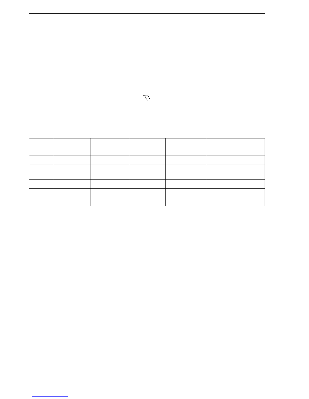
C56 Resetting to default values
-1 No
-2 Configuration and parameterization
-3 Configuration
-4 Parameterization
-5 Zero and span adjustment of the analog inputs
-6 Span adjustment of the analog outputs
-7 Code number
-8 Controller ID number
-9 Adaptation parameters
The following steps have to be carried out:
The process control station is in the OPERATING level.
1. Set configuration block C56>1 (see above and section 6.4., p.36), then exit the CONFIGURATION level again.
2. Press A key. I-O appears on the display.
3. Press D key. Ini appears on the display.
4. Press A key twice. End and Ini appear on the display.
5. Press F key to exit this level.
Note:
After having executed this function, configuration block C56 is only reset to C56-1 when it was
previously set to C56-2 or C56-3! With all other settings, the Ini level remains active! We
therefore recommend to reset the configuration block to C56-1 after carrying out the function,
in order to prevent the control station from starting up by mistake.
45
Page 46

AdP level (adaptation of the control parameters) Operation
6.13.AdP level (adaptation of the control parameters)
The objective of this adaptation function is to calculate the optimum control parameters without
the need to make many adjustments on the process control station or without having much
previous knowledge of the process to be controlled.
The TROVIS 6412/42 Process Control Station supports the following adaptation procedures:
– Single adaptation (adaptation during the start-up phase) (see section 6.13.1.)
– Scheduling dependent on the actual value signal or output variable signal (see section
6.13.2.)
– Scheduling dependent on an external signal (see section 6.13.3.)
These adaptation procedures are suitable to be used for self-regulating processes, simple
integrating controlled systems, and systems with dead times, as well as for oscillating systems.
After having terminated the adaptation procedure, the process control station uses the calcula-
ted adaptation parameters as long as − AdP on − is set in the ADAPTATION level. Otherwise,
it operates with the control parameters set in the PARAMETER level. The calculated adaptation
parameters can be viewed in the ADAPTATION PARAMETER level −PA AdP− at any time and
can also be modified by the user, except for the parameters K
K
characterizes the type of the controlled system. K3=1 characterizes a self-regulating system,
3
whereas K
=2 stands for a system which is not self-regulating.
3
The adaptation parameters calculated by the adaptation algorithm ensure an optimum behaviour of the controlled system when disturbances occur in the process. The parameter K5 can
be used to activate an adjustable filter for the set point (reference variable) in order to obtain
satisfactory reference action of the process control station when there is a step change in the
set point (reference variable).
, TN, TV and K3. The parameter
P
The current values of the controlled variable and the output variable are indicated on the display
during the entire adaptation run.
Note:
Configuration block C56-9 resets all parameters calculated in the adaptation procedure to their
default values (see also p. 45).
Requirements for adaptation
The following adjustments have to be made before conducting the adaptation:
1. Use configuration block C51 to configure the desired type of adaptation and, for cascade
control, additionally C52 (for cascade control, note section 6.13.4., p. 53; how to set a
configuration block is described in section 6.4., p. 36).
2. Regulate the controlled system, preferably in the MANUAL mode, and check whether the
system has assumed a calm state.
3. Access the ADAPTATION level and set the adaptation parameters required for the desired
adaptation procedure, see sections 6.13.1. to 6.13.3. (how to set a parameter is described
in the following sections).
46
Page 47

Operation AdP level (adaptation of the control parameters)
Opening the ADAPTATION level and accessing the adaptation steps
The process control station is in the OPERATING level. All settings required for adaptation have
been made (1. and 2.).
1. Press A key.
2. Press C key twice. AdP appears on the display.
3. Press A key. AdP and oFF appear on the display.
4. Press A key. oFF changes to on which flashes on the display.
5. Press A key. The display no longer flashes.
6. Use C and D keys to change over between the following adaptation steps:
AdP and flashing PA (adaptation parameters can be set)
AdP and flashing Aut (controller conducts adaptation automatically)
AdP and flashing nb (noise measurement can be initiated manually)
AdP and flashing idF (identification can be initiated manually; not possible until after noise
measurement)
AdP and flashing Scd and AdP (calculation of section factors can be manually initiated for
scheduling; not possible until after noise measurement and identification)
AdP and on (adaptation can be switched on/off)
7. Selected the desired adaptation step, then press the A key.
The selected adaptation step is executed.
Modifying adaptation parameters
1. Follow steps 1. to 6. as described above under "Opening the ADAPTATION level and
accessing the adaptation steps". For step 6, select PA AdP .
2. Press A key. The parameter table and AP or AP 1 appear on the display. AP stands for
the adaptation parameters of the fixed set point, follow up, ratio or synchro controller;
AP1 stands for the parameters of the master controller.
3. The individual adaptation parameters can be selected and modified in the same way as
the parameters in the PARAMETER level (see p. 32).
Completing or aborting an adaptation step
1. When defining the adaptation parameters, the parameter table and AP or AP1 appear on
the display. Press F key. Press A key for all other adaptation steps. The process control
station remains in the ADAPTATION level. An other adaptation step can be selected.
Completing or aborting the adaptation
1. Press F key. The process control station switches to the OPERATING level.
47
Page 48

AdP level (adaptation of the control parameters) Operation
6.13.1.Single adaptation (adaptation during the start-up phase)
Use C 51-2 to select single adaptation. Also use C52-2 with cascade control.
The following adaptation parameters must be set before starting the adaptation algorithm:
GW X Min. limit for the controlled variable test range in %
GW X Max. limit for the controlled variable test range in %
GW Y
GW Y
T
S K3
K
5
The adaptation algorithm runs through the steps noise band measurement (nb) and identification (idF).
In the noise measurement procedure, the noise band of the controlled variable is determined in
several tests. The sequence of operations can be followed on the display of the process control
station where changing status displays appear (see Fig. 34 ).
For the identification procedure, the operator has to excite the controlled system with a control
pulse (T
change in behaviour of the controlled system and permanently monitors the response of the
controlled variable. If the controlled variable is stationary while the pulse is still active, the
adaptation algorithm determines the type of control process, the process gain, and the dynamic
behaviour of the controlled process, and calculates the control parameters for, e.g. an
increasing output signal.
Min. limit for the output variable test range in %
1
Max. limit for the output variable test range in %
1
Pulse duration of the output test signal in s (for positive values) and min (for
negative values)
Factor for set point (reference variable) filter
) whose time and amplitude is limited. Then, the process control station waits for any
SK3
The controlled variable is considered to be stationary when it does not exceed or fall below a
factory-adjusted deviation for a certain period of time.
The control pulse is switched off when the control parameters for the increasing output signal
have been calculated. The control station monitors the behaviour of the controlled system again.
When the controlled variable is stationary, the control station calculates the parameters for a
decreasing output signal.
Should the controlled variable not become stationary, the process control station will provide
an error message (see p. 90).
If the controlled variable threatens to leave the test range (adjusted by the operator) after
exciting the controlled system, the control pulse is inactivated. A new amplitude-corrected pulse
value is calculated from the characteristic of the controlled variable until the time when the pulse
is switched off, and the procedure described above is repeated.
The pulse is also switched off when it exceeds the pulse time. Then, the same takes place as
described above.
In the identification procedure, the adaptation steps are indicated on the display of the process
control station in the sequence illustrated in Fig. 35. Individual steps are omitted, depending on
which type of controlled system was determined.
The adaptation procedure can run automatically. Then, the adaptation step −Aut AdP− has to
be accessed in the ADAPTATION level (see p. 46). At the end of the adaptation cycle, End Aut
comes up on the display. The operator can carry out each adaptation step individually. In this
case, first access adaptation step −nb AdP− , then −IbF AdP− (see p 46).
48
Page 49

Operation AdP level (adaptation of the control parameters)
Display field Status display Sequence of operations
0 Checks starting condition
1Start
Measurement 1st interval
2 Measurement 2nd interval
Calculates noise band
3 Measurement 3rd interval
Calculates noise band
4 Measurement 4th interval
Calculates noise band
5 Measurement 5th interval
Calculates noise band
End
nb
End of noise measurement
Fig. 34 ⋅ Operational flow chart for noise measurement
49
Page 50

AdP level (adaptation of the control parameters) Operation
Display field Status
display
t >TsK
3
X >GWX
t >TsK
3
1)
1)
System with self-regulation
2)
System without self-regulation
2)
End
Sequence of operations
0 Checks starting condition
Checks if system has assumed
a calm state
1 Checks if pulse was imposed
on system
2 Activates control pulse
Waits for system response
3 System response determined
4 Controlled system stationary
First calculation of control
parameter set 1 (basic values)
Inactivates control pulse
for system response
5 Inactivates control pulse for
system response
6 Inactivates control pulse
First calculation of control
parameter sets 1 and 2 (basic
values).
Changes over to selected
operating mode or
calculates correction of
control pulse
Waits for system
to become stationary
7 Activates corrected control
pulse
Waits for system response
8 System response determined
Waits for system to
become stationary
First calculation of control
parameter set 1 (basic values)
9 Inactivates control pulse
Waits for system response
10 System response determined
Waits for system to
become stationary
First calculation of control
parameter set 2 (basic values)
Changes over to selected
operating mode
End of identification
IdF
Fig. 35 ⋅ Operational flow chart for identification
50
Page 51

Operation AdP level (adaptation of the control parameters)
6.13.2.Scheduling dependent on the actual value signal or output variable signal
Scheduling dependent on the actual value signal has to be selected with configuration block
C51-3, whereas scheduling dependent on the output variable signal has to be configured with
C51-4. In the cascade control mode, C52-3 or C52-4 can be set to implement adaptation for
the master controller loop. Note that scheduling is only supported in systems with self-regulation.
The following parameters must be set before starting the adaptation algorithm:
All parameters as for single adaptation (see section 6.13.1.) and additionally:
GW K
GW K
K
4
Min. limit for the adaptation range in %
2
Max. limit for the adaptation range in %
2
Number of sections (maximum 7)
For scheduling dependent on the actual value signal, the control station must be put to the
AUTOMATIC mode.
Scheduling has the objective to compensate for measurable, static non-linearities occurring in
a process. This scheduling procedure is used to determine the optimum controller settings for
definable sections of a selected adaptation range. The operator can choose among two
scheduling procedures: 1) scheduling dependent on the controlled variable (CO 51-3) or 2)
scheduling dependent on the output variable (CO 51-4). As already described above, limits
for the adaptation range have to be entered, meaning, for example a range for the controlled
variable. In addition, the number of sections into which this adaptation range shall be divided
have to be defined. In the scheduling procedure, the controller calculates a factor for each of
these sections, which modifies the proportional-action coefficient K
stored as parameters K
to K7. The reference points for the scheduling procedure are
1
These section factors are
p.
located in the middle of each section. The control parameters are linearly interpolated between
these reference points. The values calculated before the first and after the last reference point
are maintained constant.
First, the scheduling algorithm runs through the steps described in section 6.13.1.. Then, the
process control station goes to the lower limit of the defined adaptation range and waits for the
controlled system to become stationary. As soon as the system is stationary, the control station
accesses the first operating point. This is done abruptly (step change) with scheduling dependent
on the output variable and regularly (controlled) with scheduling dependent on the controlled
variable. The operating points are located exactly on the limits of the individual sections. After
having gone to the operating point, the process control station waits again for the controlled
system to become stationary. Subsequently, the adaptation algorithm calculates the factor for
the respective section. The procedure described above is repeated for each section.
The last part of the scheduling procedure can be followed on the display of the process control
station as described in Fig. 36 .
As for single adaptation, the scheduling steps either run automatically (AdP Aut) one after the
other or each step can be accessed individually (nb-idF-Scd), see. p. 46.
Also, it is possible to set all parameters to be calculated in the ADAPTATION PARAMETER level.
51
Page 52

AdP level (adaptation of the control parameters) Operation
Display field Status display Sequence of operations
0 Checks starting condition
Control pulse
Beginning of adaptation range
Waits for system to become stationary
1 Control pulse for 1st section
Waits for system to become stationary
Calculates section factor K
1
2 Control pulse for 2nd section
Waits for system to become stationary
Calculates section factor K
2
3 Control pulse for 3rd section
Waits for system to become stationary
Calculates section factor K
3
4 Control pulse for 4th section
Waits for system to become stationary
Calculates section factor K
5 Control pulse for 5th section
Waits for system to become stationary
Calculates section factor K
6 Control pulse for 6th section
Waits for system to become stationary
Calculates section factor K
7 Control pulse for 7th section
Waits for system to become stationary
Calculates section factor K
Changes over to selected
operating mode
End
End of scheduling
Scd
4
5
6
7
Fig. 36 ⋅ Operational flow chart for scheduling
52
Page 53

Operation AdP level (adaptation of the control parameters)
6.13.3.Scheduling dependent on an external signal
Scheduling dependent on the Y
-signal has to be selected with configuration block C51-5,
Actuat
whereas scheduling dependent on the Z-signal has to be configured with C51-6. In the cascade
control mode, C52-5 or C52-6 can also be set to implement adaptation for the master controller
loop.
The following parameters must be set before starting the adaptation algorithm:
All parameters as for single adaptation (see section 6.13.1.) and additionally:
GW K
GW K
Min. limit for the adaptation range in %
2
Max. limit for the adaptation range in %
2
K4 Number of sections (maximum 7)
to K7 Factor for sections 1 to 7
K
1
The scheduling procedure dependent on an external signal is the same as the one dependent
on the controlled variable or output variable signal (see section 6.13.2.). The section factors,
however, are not calculated by the adaptation algorithm, but have to be entered manually in
the ADAPTATION PARAMETER level PA AdP.
The adaptation range set in the factory is 10% to 90 %. The section factors are assigned the
value 1.
6.13.4.Notes on adaptation
In a cascade control arrangement, adaptation must be first carried out in the follow-up or
secondary control loop. The operator has to open the cascade in the OPERATING level (press
B key). Then, a
appears in the top right corner of the display. The control station can be put
either in the MANUAL or AUTOMATIC mode. After having carried out adaptation for the
follow-up control loop, the cascade must be closed (press B key) and the controller must be set
to the AUTOMATIC mode. Subsequently, adaptation can be implemented for the master
controller loop.
The factory settings for the controlled variable test range and the output variable test range for
adaptation are from 10 % to 90 %. If the operator modifies these two values, the two values
should always be the same in the beginning. Should the control station indicate insufficient
oscillation of the controlled variable during adaptation (cin 202, accept with A key), the output
variable test range (GWY
length of the control pulse (T
, GWY1) has to be expanded or, if this is not permitted, the
1
) has to be increased.
SK3
In case of an error, the adaptation algorithm provides different error messages. These are
described in more detail in the table Error messages starting on page 90.
53
Page 54

AdP level (adaptation of the control parameters) Operation
6.13.5.Summary of the adaptation parameters
The parameters characterized by AP apply for fixed set point, follow-up, ratio, and synchro
control, as well as for the follow-up control loop in cascade control arrangements.
The parameters characterized by AP1 apply for the master control loop in a cascade control
arrangement.
Parameter
K
P
T
N
T
V
K
3
K
5
GWK
GWX
GWX
GWY1
GWY1
GWK
GWK
T
SK3
K
1
TZK
1
K
2
TZK
2
K
PK1
T
NK1
T
VK1
K
PK2
T
NK2
T
VK2
K
4
K
1
K
2
K
3
K
4
K
5
K
6
K
7
K
P
Parameter-
Designation Range of values Factory
default
set
AP Proportional-action coefficient 0.1 … 100.0
AP Reset time -1999 … 1999
AP Rate time -1999 … 1999
AP Type of controlled system
1)
0 … 20
AP Factor for set point (reference variable) filter 0.00 … 19.99 0.00
AP Noise bandwidth 0.1 … 10.0 0.0
1
AP Min. limit for the controlled variable test range 0.0 … 110.0 10.0
AP Max. limit for the controlled variable test range 0.0 … 110.0 90.0
AP Min. limit for the output variable test range 0.0 … 110.0 10.0
AP Max. limit for the output variable test range 0.0 … 110.0 90.0
AP Min. limit for the adaptation range 0.0 … 110.0 10.0
2
AP Max. limit for the adaptation range 0.0 … 110.0 90.0
2
AP Pulse duration, control pulse (output test signal) -1999 … 1999 50.0
AP System gain (increasing output signal) 0.1 … 100.0 0.0
AP Dead time (increasing output signal) -1999 … 1999 0.0
AP System gain (decreasing output signal) 0.1 … 100.0 0.0
AP Dead time (decreasing output signal) -1999 … 1999 0.0
AP Basic value (increasing output signal) P-coeff. 0.1 … 100.0 1.0
AP Basic value (increasing output signal) reset time -1999 … 1999 60.0
AP Basic value (increasing output signal) rate time -1999 … 1999 5.0
AP Basic value (decreasing output signal) P-coeff. 0.1 … 100.0 1.0
AP Basic value (decreasing output signal) reset time -1999 … 1999 60.0
AP Basic value (decreasing output signal) rate time -1999 … 1999 5.0
AP Number of sections 1 … 75
AP Section factor 1 0.00 … 19.99 1.00
AP Section factor 2 0.00 … 19.99 1.00
AP Section factor 3 0.00 … 19.99 1.00
AP Section factor 4 0.00 … 19.99 1.00
AP Section factor 5 0.00 … 19.99 1,00
AP Section factor 6 0.00 … 19.99 1.00
AP Section factor 7 0.00 … 19.99 1.00
AP1 Proportional-action coefficient 0.1 … 100.0
54
Page 55

Operation AdP level (adaptation of the control parameters)
Parameter
Parameter-
Designation Range of values Factory
set
T
N
T
V
K
3
K
5
GWK
GWX
GWX
GWY1
GWY1
GWK
GWK
T
SK3
K
1
TZK
1
K
2
TZK
2
K
PK1
T
NK1
T
VK1
K
PK2
T
NK2
T
VK2
K
4
K
1
K
2
K
3
K
4
K
5
K
6
K
7
1)
1: System with self-regulation
AP1 Reset time -1999 … 1999
AP1 Rate time -1999 … 1999
AP1 Type of controlled variable
AP1 Factor for set point (reference variable) filter 0.00 … 19.99 0.00
AP1 Noise bandwidth 0.1 … 10.0 0.0
1
AP1 Min. limit for the controlled variable test range 0.0 … 110.0 10.0
AP1 Max. limit for the controlled variable test range 0.0 … 110.0 90.0
AP1 Min. limit for the output variable test range 0.0 … 110.0 10.0
AP1 Max. limit for the output variable test range 0.0 … 110.0 90.0
AP1 Min. limit for the adaptation range 0.0 … 110.0 10.0
2
AP1 Max. limit for the adaptation range 0.0 … 110.0 90.0
2
AP Pulse duration, control pulse (output test signal) -1999 … 1999 50.0
AP1 System gain (increasing output signal) 0.1 … 100.0 0.0
AP1 Dead time (increasing output signal) -1999 … 1999 0.0
AP1 System gain (decreasing output signal) 0.1 … 100.0 0.0
AP1 Dead time (decreasing output signal) -1999 … 1999 0.0
AP1 Basic value (increasing output signal) P-coeff. 0.1 … 100.0 0.1
AP1 Basic value (increasing output signal) reset time -1999 … 1999 240
AP1 Basic value (increasing output signal) rate time -1999 … 1999 20.0
AP1 Basic value (decreasing output signal) P-coeff. 0.1 … 100.0 0.1
AP1 Basic value (decreasing output signal) reset time -1999 … 1999 240
AP1 Basic value (decreasing output signal) rate time -1999 … 1999 20.0
AP1 Number of sections 1 … 75
AP1 Section factor 1 0.00 … 19.99 1.00
AP1 Section factor 2 0.00 … 19.99 1.00
AP1 Section factor 3 0.00 … 19.99 1.00
AP1 Section factor 4 0.00 … 19.99 1.00
AP1 Section factor 5 0.00 … 19.99 1.00
AP1 Section factor 6 0.00 … 19.99 1.00
AP1 Section factor 7 0.00 … 19.99 1.00
2: System without self-regulation
default
1)
0 … 20
55
Page 56

7.TROVIS 6482 Configuration and Parameterization Program
The TROVIS 6482 Configuration and Parameterization software program is a user-friendly MS
Windows application. In addition to entering configuration and parameter data, this program
also contains functions for documenting the process control station. These functions are, for
example editing of plant texts, printing of configuration and parameter data, storage of
different parameter and configuration data, and graphical display of analog inputs and
outputs, as well as binary status displays.
The TROVIS 6482 Configuration and Parameterization program runs under Windows 3.1 or
higher. The user is required to have previous knowledge of other Windows programs, which
should enable him to easily operate TROVIS 6482.
TROVIS 6482 comes together with a special COPA adapter (configuration and parameterization adapter, order no. 1170-1141). This adapter enables the user to couple the process control
station with a PC via the front-panel serial interface. One side of the COPA adapter is a
connector, designed for connecting it to the front-panel of the process control station, whereas
the other side is a 9 pin D sub socket which connects to the Com1 or Com2 interface of the PC.
56
Page 57

COM1/
COM2/
COM3/
COM4
Fig. 37 ⋅ Connecting the COPA adapter to the PC
57
Page 58

8.COPA pen
The COPA pen (COnfiguration and PArameterization pen) can be used to write to or read from
the process control station all data applicable to the CONFIGURATION or PARAMETER levels.
In this way, it is possible to quickly transfer data to other TROVIS 6412 or 6442 Process Control
Stations.
The COPA pen is assigned an identification number which is transferred to it when data is
written to the pen. This number can only be defined in the TROVIS 6482 Configuration and
Parameterization Program as any value between 0 and 1999, and can be used, for example
for a special configuration. When plugging the COPA pen into the process control station, the
control station first compares the identification number of the COPA pen with its own
identification number. If these ID numbers do not correspond, COP and the identification
number of the COPA pen, as well as C and the identification number of the process control
station alternate on the display. In this case, data transfer is only possible when:
– The ID number of the COPA pen is 0 or
– The ID number of the process control station is 0 or was reset respectively. The ID number
of the process control station can be reset with C56-8, see section 6.12., p. 45.
Proceed as follows to transfer data to or retrieve data from the COPA pen:
1. Plug COPA pen with the white marking facing upwards into the associated connector (1)
located on the front-panel of the process control station. COP and the ID number appear
on the display. If the ID numbers of pen and process control station do not correspond, the
display alternates as described above.
2. Press A key. C and out (flashes) appear on the display. With this setting, data can be read
from the process control station.
If the data contents of the COPA pen shall be written to the process control station, press
C or D key so that COP appears in the upper line of the display.
3. Press A key. After approx. 1 s End comes up in the lower line of the display.
4. Remove COPA pen. After having transferred data from the COPA pen to the process
control station, the MANUAL mode is active.
1
Fig. 38 ⋅ Connecting the COPA pen
58
1 Interface for COPA
pen (adapter)
Page 59

Fig. 39 ⋅ Simplified diagram showing how to use the COPA pen
59
Page 60

Interface mode Interface RS-485
9.Interface RS-485
The process control station can be optionally equipped with a serial RS-485 interface. This
interface enables the user to integrate TROVIS 6412 into a process control system and, by
means of a suitable software, establish a complete automation system for process control
applications. The hardware configuration needed for such an automation system is described
in section 9.2. The serial interface hardware meets the RS-485 (RS = Recommended Standard
acc. to EIA) requirements. Communication is based on the Modbus protocol. The functions
supported by the Modbus protocol are described in section 9.5. Other data are listed in the
table "Technical data", starting on page 8.
The RS-485 interface of the process control station is a PCB (printed circuit board) which is
installed in the associated slot of the controller case (see p. 13 , Fig. 5 ). If the TROVIS 6412
process control station is retrofitted with this interface board, proceed as described in section 9.6..
Fig. 7 , p. 22 and Fig. 9 , p. 24 show how to connect the data lines, based on the controller
case version used.
9.1.Interface mode
Several settings of the RS-485 interface are made by means of soldering jumpers. Please note
section 4.4., p. 20. The soldering jumpers on the interface board determine the baud rate, the
bus termination, two-wire or four-wire connection, and the character parity.
When the RS-485 interface is to be used for communication, the following parameters have to
be set in the Si level (See also section 6.6., p. 40).
– Station number (Address of process control station, range of values from 1 to 246)
– Timeout period (During this time, the central control station must have interrogated the
process control station at least once. Otherwise an error is indicated on the display of the
process control station. The Timeout period is only valid, when the status Timeout period
is switched on (see below); range of values: −1999 to −1 for minutes; 0.1 to 1999 for
seconds.)
– Status Timeout period (Timeout period can be switched −on− or −oFF−)
– Status RS-485 interface (switch interface mode −on− or −oFF−)
The interface mode is active as soon as the status RS-485 interface is switched on.
If internal communication between the process control station and the RS-485 interface is
interrupted, an error is indicated after 10 s. At the same time, the symbol
for "external
system not ready" flashes on the display.
9.2.Network construction
Fig. 40 shows an example how to construct a network for an automation system in which data
exchange is based on the Modbus protocol. A total amount of maximum 246 devices can be
interrogated. First a converter, which converts the RS-232 signal from the PC into a RS-485
signal, has to be connected to the PC. A repeater is to be provided if the connecting lines are
longer than 1200 m or more than 32 stations are connected to the bus. We recommend to
connect a maximum of three repeaters in series. In this way, the connecting lines can cover a
distance of up to 4800 m. A max. of 10 such lines can be connected in parallel when further
expanding the network. A bus termination is to be provided at the end of each line segment,
for example between converter and repeater, in order to discharge highly-resistive voltages.
60
Page 61

Interface RS-485 Network construction
1Converter
2 Repeater
3 TROVIS 6412
1
RS 485
RS 232
3
3
Maximum
28 devices
3
2
RS 485
2
RS 485
RS 485
2
RS 485
RS 485
Maximum
28 devices
Maximum
30 devices
3
Fig. 40 ⋅ Constructing a network with converters and repeaters
RS 485
Maximum
31 devices
61
Page 62

Network interconnections Interface RS-485
9.3.Network interconnections
The individual network components can communicate with each other via the Modbus protocol,
both in a four-wire system and in a two-plus-two-wire system.
In a four-wire system, the repeaters automatically switch over the direction of data transmission.
In the two-plus-two-wire system, the direction of data transmission is determined by two control
lines.
9.4.Operation
The RS-485 interface is assigned its own operating level which is described in section 6.6., p. 40.
9.5.Functions supported by the Modbus protocol
The Modbus protocol covers the rules for communication between the process control station
and the central control station. It is a master-slave protocol where the central control station is
the master and the process control station is the slave. The process control station (slave) can
therefore only reply to queries from the central control station. The Modbus function codes
supported by the process control station are described in the following and explained by means
of examples.
9.5.1.Function code 01 (Read Coil Status)
This function code allows to read binary information such as fault alarms, relay states or
operating messages from the process control station and transmit these to the central control
station.
Example: Read coils 10 to 21 from the process control station with the address 11.
Query from the central control station
Address Function Starting address Quantity of coils Checksum
high low high low low high
0B 01 00 0A 00 0C 1C A7
Response of the process control station
Address Function Quantity
of bytes
0B 01 02 A3 02 D8 CC
In this example, coils 10, 11, 15, 17 and 19 are set to "1". The coils in the byte have to be
read from the right to the left.
Coil 17 16 15 14 13 12 11 10
Byte 1 Byte 2 Checksum
Coil 10…17 Coil 18…21 low high
10100011= A3
The second byte contains the coils 18 to 21. The first four bits are "0".
Coil X X X X 21201918
00000010= 02
62
H
H
Page 63

Interface RS-485 Functions supported by the Modbus protocol
9.5.2.Function code 02 (Read Input Status)
This function code allows to read the current status of the binary inputs bi 1, bi 2 and bi 3
directly at the input of the slave, no matter whether the respective binary input was configured
in the process control station.
For the query from the central control station and the response from the process control station,
see Read Coil Status (Function code 01).
9.5.3.Function code 05 (Force Single Coil)
The central control station can modify a logic condition in the process control station.
Example: Write coil 09 (MANUAL/AUTOMATIC changeover).
coil 09 must set to "0" in order to place the process control station in the AUTOMATIC mode.
In this example, the address of the process control station is 12.
Query from the control station
Address Function Coil Coil Checksum
high low on off low high
0C 05 00 09 FF 00 5D 25
Response from the process control station
Address Function Coil Coil Checksum
high low on/off low high
0C 05 00 09 FF 00 5D 25
The fourth byte contains number 9 (hexadecimal). If a coil is set to "1", byte 5 must transmit the
information FF. If it is to be deleted, 00 has to be transmitted.
9.5.4.Function code 03 (Read Holding Register)
Analog variables can be read from the process control station and, after conversion to the
numeric format, displayed on the PC (controlled variable, set point (reference variable) etc.),.
Example: Read holding register no. 1
This register contains the device identification. The address of the process control station is 1.
Query from the control station
Address Function Holding register no. Quant. of holding registers Checksum
high low high low low high
01 03 00 00 00 01 84 0A
Response from process control station
Address Function Quantity of
01 03 02 19 0C B3 D1
Since, in this example, only register 1 is read and this register always contains the decimal
value 6412, it can be used to check the device identification.
bytes
Value of register 1 Checksum
high low low high
63
Page 64

Functions supported by the Modbus protocol Interface RS-485
9.5.5.Function code 04 (Read Input Register)
With this function code, the current status of the analog inputs in 1, in 2, in 3 and in 4 can be
read directly at the input of the slave, no matter whether the respective analog input has been
assigned the variable X, W
, Z or Y
EX
ACTUAT
.
For the query from the central control station and response from the process control station, see
Read Holding Register (Function code 03).
9.5.6.Function code 06 (Preset Single Register)
With this function code, analog values, such as the value of the set point (reference variable)
or K
can be modified.
P
Example: Write holding register 106.
This is the value of the set point (reference variable) which can be written serially. The process
control station has the station address 18 and operates as a fixed set point controller. A set
point (reference variable) value of 10.0 is to be transmitted from the central control station to
the process control station.
Query from the central control station
Address Function Holding register no. Value in register 35 Checksum
high low high low low high
12 06 00 6A 00 64 AA 9E
Response from the process control station
Address Function Holding register no. Value in register 35 Checksum
high low high low low high
12 06 00 6A 00 64 AA 9E
9.5.7.Function code 15 (Force Multiple Coils)
This function code allows modifying the status of multiple coils.
Example: 10 coils, starting at address 20 (13
the address 17. For this purpose, two bytes are transmitted.
Byte 1 = CDH =11001101
Coil no. 2726252423222120
Byte 2 = 00
Coil no. 0000002928
=00000000
H
), are written to the process control station with
H
In this example, "1" is written to coils 27, 26, 23, 22 and 20; "0" is written to the remaining
coils.
Query from the central control station
Address Function Coil address Quant. of coils Byte count
high low high low 20 to 27 28 to 29 low high
11 0F 00 13 00 0A 02 CD 00 7E CB
64
Data coil Data coil CRC
field
Page 65

Interface RS-485 Functions supported by the Modbus protocol
Response from the process control station
Address Function Coil address Quantity of coils CRC
high low high low low high
11 0F 00 13 00 0A 26 99
The master only writes to coils that are marked with R/W. When attempts are made to write to
Read-Only coils, no error message is issued by the process control station. The Modbus
response is sent while the Write command is still being carried out. It is therefore possible that
any following Write commands are answered with error code 6 ("Busy").
9.5.8.Function code 16 (Preset Multiple Register)
This function code is used to modify values of multiple holding registers.
Example: Two holding registers, starting at address 135, are sent to the process control station
with the device address 17.
Query from the central control station
Address Function Address Quant. holding reg. Byte
high low high low high low high low low high
11 10 00 87 00 02 04 00 0A 01 02 4E BA
count field
1 data value 2 data value CRC
The value 10 (corresponds to 000AH) is placed into holding register 13 and the value 258
(corresponds to 0102
Response from the process control station
Address Function Coil address Quantity of coils CRC
11 10 00 87 00 02 F3 71
) is placed into holding register 136.
H
high low high low low high
The master only writes to coils that are marked with R/W. When attempts are made to write to
Read-Only coils, no error message is issued by the process control station. The Modbus
response is sent while the Write command is still being carried out. It is therefore possible that
any following Write commands are answered with error code 6 ("Busy").
9.5.9.Error messages
The process control station responds with an error message upon illegal operations between
the control station (Modbus-Master) and the process control station (Modbus slave):
– Error code 01: Illegal function requested
– Error code 02: Query containing an undefined data address
– Error code 03: Query containing an illegal data value
– Error code 06: Query while the process control station is busy, COPA pin or COPA
adapter with software TROVIS 6482 are being used ("Busy" message)
65
Page 66

Retrofitting the RS-485 interface Interface RS-485
Example: Query for the undefined holding register 500
Query from the central control station
Address Function Addressholding register Quantity holding registers Checksum
high low high low low high
01 03 01 F4 00 01 C4 04
Response from the process control station
Address Function Error message Checksum
low high
01 83 02 C0 F1
In case of an error, the function byte is combined exclusive OR with 80H, i.e. bit 7 is set. This
indicates the master (central control station) that an error has occurred.
9.5.10.Other functions
Broadcast commands of the central control station are supported.
9.6.Retrofitting the RS-485 interface
Important! When retrofitting the interface board, the soldering jumpers LB1, LB2 and LB3 on
the logic board have to be closed (see section 4.2., p. 19).
Install the interface board as follows:
1. Open case of the process control station, see p. 12, section 3.3. , step 1.
2. Withdraw the controller unit from the case from the front side.
3. Unscrew the four screws (1, 2) and remove the two distance bolts (4) (see Fig. 5 , p.13).
4. Carefully withdraw the input board from the case.
5. Insert the interface board in the associated slot (s. p. 13 , Fig. 5 ), making sure that the
components on the board face the input board and the logic board.
6. Reinstall the input board.
7. Then proceed as described under 8. to 10. in section 3.3., p. 13.
66
Page 67

Start-up procedure Optimization (tuning the process control station to the controlled system)
10.Start-up procedure
Before installing or putting the process control station into operation, all characteristics of the
input and output signals and the code number have to be determined by means of the
associated soldering jumpers (see section 4., p. 14).
When all input and output connections are made and power is supplied to the process control
station, it has to be tuned for the respective control task. For this purpose, the process control
station must be configured. This can be done either manually by setting the configuration blocks
in the CONFIGURATION level (see section 6.4.), by means of a COPA pen (see section 8.), or
by using the TROVIS 6482 Configuration and Parameterization Program (see section 7.). The
configuration settings made can be recorded in a checklist given in Appendix C . The TROVIS
6482 Configuration and Parameterization Program provides the option of printing a similar
list on request. The options assigned to the individual configuration blocks are described in
more detail in Configuration manual KH 6412 E.
The parameters K
, TN and Tv can be set and modified either by means of the adaptation
P
algorithm of the process control station (see section 6.13., p. 46) or in a manual optimization
procedure. The latter is described in general in the following section.
10.1.Optimization (tuning the process control station to the controlled system)
The process control station must be tuned to the dynamic behaviour of the loop, using the
parameters K
by reducing these to zero or maintain them in very confined limits.
If you do not have previous experience in selecting values for the control loop, proceed
according to the following basic procedure:
The connected control valve must be closed, before starting the optimization.
1. Switch the MANUAL/AUTOMATIC mode selector key (E) to MANUAL mode. The
symbol comes up on the display.
2. Hold down the (H) key until only the first bar of the bar graph for the output variable (14)
is displayed.
3. Proceed according to the control mode selected (see below).
Proportional (P) controller
–Specify K
– Enter the desired value of the set point (reference variable) in the OPERATING level.
, TN and Tv in order to compensate for control deviations caused by disturbances
P
= 0.1 in the PARAMETER level.
P
– Then modify the output variable by pressing the (G) key until the control valve slowly opens
and the error X
is eliminated.
d
– Switch over to AUTOMATIC mode by pressing the MANUAL/AUTOMATIC key.
– Increase the K
value in the PARAMETER level until the controlled systems tends to hunt.
P
– Slightly reduce the K
– Eliminate steady-state deviation as follows: Switch the controller to the MANUAL mode.
Modify the output variable until the error X
and enter this value for parameter K
Important: Any modification of the set point (reference variable) causes a change of the
operating point K
!
1
value until oscillation cannot be determined any more.
P
= 0. Read off the displayed output variable
d
.
1
67
Page 68

Optimization (tuning the process control station to the controlled system) Start-up procedure
Proportional-plus-integral (PI) controller
–Specify K
= 0.1 ; TN = 1999 in the PARAMETER level.
P
– Enter the value of the desired set point (reference variable) in the OPERATING level.
– Then modify the output variable by pressing the (G) key until the control valve slowly opens
and the error X
is eliminated.
d
– Switch over to AUTOMATIC mode by pressing the MANUAL/AUTOMATIC key.
–Increase the K
– Slightly reduce the K
– Reduce the T
– Slightly increase the T
value in the PARAMETER level until the controlled system tends to hunt.
P
value until oscillation cannot be determined any more.
P
value in the PARAMETER level until the controlled system tends to hunt.
N
value until oscillation cannot be determined any more.
N
Proportional-plus-derivative (PD) controller
–Specify K
= 0.1; Tv = 1 and the rate gain TvK1 = 1 in the PARAMETER level.
P
– Enter the value of the desired set point (reference variable) in the OPERATING level.
– Then modify the output variable by pressing the (G) key until the control valve slowly opens
and the error X
is eliminated.
d
– Switch over to AUTOMATIC mode by pressing the MANUAL/AUTOMATIC key.
–Increase the K
value in the PARAMETER level until the controlled system tends to hunt.
P
– Increase the Tv value until oscillation cannot be determined any more.
–Increase the K
value until oscillation reoccurs.
P
– Increase the Tv value again until oscillation cannot be determined any more.
– Repeat this procedure several times until oscillation cannot be suppressed any longer.
– Slightly reduce the K
value and the Tv value so that the system can recover.
P
– Eliminate steady-state deviation as follows:
– Set configuration block C28-2. This activates setting of the operating point via the
MANUAL mode.
– Switch to MANUAL mode by pressing the MANUAL/AUTOMATIC key.
– Modify the output variable until the error X
is eliminated.
d
– Switch to AUTOMATIC mode by pressing the MANUAL/AUTOMATIC key.
The output variable is stored and applied to the controller output as operating point.
Important: Any modification of the set point (reference variable) causes a change of the
operating point.
68
Page 69

Start-up procedure Optimization (tuning the process control station to the controlled system)
Proportional-plus-integral-plug-derivative (PID) controller
–Specify K
= 0.1 ; TN = 1999 and Tv = 1 in the PARAMETER level.
P
– Enter the value of the desired set point (reference variable) in the OPERATING level.
– Then modify the output variable by pressing the (G) key until the control valve slowly opens
and the error X
is eliminated.
d
– Switch over to AUTOMATIC mode by pressing the MANUAL/AUTOMATIC key.
– Increase the K
value in the PARAMETER level until the controlled system tends to hunt.
P
– Increase the Tv value until oscillation cannot be determined any more.
– Increase the K
value until oscillation reoccurs.
P
– Increase the Tv value again until oscillation cannot be determined any more.
– Repeat this procedure several times until oscillation cannot be suppressed any longer.
– Slightly reduce the K
– Reduce the T
value until the control loop tends to hunt again, and then slightly increase
N
value and the Tv value so that the system can recover.
P
value again until oscillation cannot be determined any more.
69
Page 70

Page 71

Appendix A Data Point List for the RS 485-Interface
Holding Registers Data Point List
HR
No.
Designation of data point Access 1)Transmission
range
Display range Comments
1 Device identification R 6412 6412 Register only readable;
transmits the device
identification
2 Variant/version R 100 … 64999 0…64/1.00…9.99 0 = Standard variant
1 = Special variant
2 = Development variant
/version number
Controller inputs according to their assignment to the analog inputs (C10,C11,C12,C13)
3 X
R/W -200 … 1200 -20.0% …120.0%
6)
Internally used variables
according to their
assignment to the
analog inputs; can only
be written to when no
analog input is assigned
4W
EX
R/W -200 … 1200 -20.0% …120.0%
6)
5 Z
R/W -200 … 1200 -20.0% …120.0%
6)
6Y
STELL
R/W -200 … 1200 -20.0% …120.0%
6)
Analog outputs
7Y
1
R -100 … 1100 -10.0% … 110.0% Analog variables which
are available at the
respective analog output
8Y
2
R -100 … 1100 -10.0% … 110.0%
9 Ao1
R -100 … 1100 -10.0% … 110.0%
Operating data
10 Set point (reference variable) display 1 acc. to C4 R -100 … 1100 -10.0% … 110.0%
11 Controlled variable display 1 acc. to C4 R -100 … 1100 -10.0% … 110.0%
12 Set point (reference variable) display 2 acc. to C4 R -100 … 1100 -10.0% … 110.0%
13 Controlled variable display 2 acc. to C4 R -100 … 1100 -10.0% … 110.0%
71
Page 72

HR
No.
Designation of data point Access 1)Transmission
range
Display range Comments
14 Internal Y
PID
-signal R/W -100 … 1100 -10.0% … 110.0% Adjustable in MANUAL
mode
15 Controller ID number R/W
10)
0 … 19990 0.0 … 1999.0 4-digit number to
identify the controller in
the plant, see also p. 58
16 Timeout period Interface R/W
10)
-19990… -10
10 … 19990
-1999.0…-1.0 (minutes)
1.0…1999.0 (seconds)
Time during which the
device must have been
interrogated at least once
by the central control
station, otherwise cin 6
error display and LED
and bo3 alternate
17 Reserved
18 Reserved
19 Reserved
20 Reserved
21 Reserved
Status messages
22 Transmitter fault R 0 … 65535 0 … 15 Display: Values out of
measuring range
23 Checksum error Data R 0 … 65535 0 … 32
5)
Checksum of
permanently stored data
has changed without
operator intervention;
check data
24 Program error Data R 0 … 65535 0 … 16
5)
Re-program
25 Adaptation Status R 0 … 65535 0 …100
9)
26 Adaptation Program R 0 … 65535 0 … 255
9)
27 Programming Status R 0 … 65535 0 … 255
9)
72
Page 73

HR
No.
Designation of data point Access 1)Transmission
range
Display range Comments
28 Programming Error R 0 … 65535 0 …255
9)
29 Reserved
Configuration blocks
7), 10)
Details, see
KH 6412 E
30 C 1 Control mode R/W
10)
0 … 16 0 … 16
31 C 2 Secondary controlled variable/feedforward control R/W
10)
0 … 16 0 … 16
32 C 3 Calculation specification, feedforward control R/W
10)
0 … 16 0 … 16
33 C 4 Configuration of digital displays R/W
10)
0 … 16 0 … 16
34 C 5 Configuration of controller outputs R/W
10)
0 … 16 0 … 16
35 C 6 Inversion of error signal R/W
10)
0 … 16 0 … 16
36 C 7 Function generation R/W
10)
0 … 16 0 … 16
37 C 8 Combination of input variables R/W
10)
0 … 16 0 … 16
38 C 9 Root extraction of input variables R/W
10)
0 … 16 0 … 16
39 C10 Assignment of controller inputs to X - input R/W
10)
0 … 16 0 … 16
40 C11 Assignment of controller inputs to W
EX
- input R/W
10)
0 … 16 0 … 16
41 C12 Assignment of controller inputs to Z - input R/W
10)
0 … 16 0 … 16
42 C13 Assignment of controller inputs to Y
ACTUAT.
- input R/W
10)
0 … 16 0 … 16
43 C14 Zero and span adjustment, analog inputs and
outputs
R/W
10)
0 … 16 0 … 16
44 C15 Monitoring of measuring range R/W
10)
0 … 16 0 … 16
45 C16 Set point (reference variable) ramp R/W
10)
0 … 16 0 … 16
46 C17 Configuration of binary input bi 1 R/W
10)
0 … 16 0 … 16
47 C18 Configuration of binary input bi 2 R/W
10)
0 … 16 0 … 16
48 C19 Configuration of binary input bi 3 R/W
10)
0 … 16 0 … 16
49 C20 Set point (reference variable) limitation or
reciprocal set point or actual value ratio
R/W
10)
0 … 16 0 … 16
50 C21 Set point (ref. variable ) upon failure of external system R/W
10)
0 … 16 0 … 16
51 C22 Assignment of internal set point R/W
10)
0 … 16 0 … 16
73
Page 74

HR
No.
Designation of data point Access 1)Transmission
range
Display range Comments
52 C23 X-tracking R/W
10)
0 … 16 0 … 16
53 C24 Dynamic behaviour of controller output R/W
10)
0 … 16 0 … 16
54 C25 Dynamic behaviour of controller output (MaC, LiC) R/W
10)
0 … 16 0 … 16
55 C26 Assignment of D-element R/W
10)
0 … 16 0 … 16
56 C27 Filtering of input variables and error signal R/W
10)
0 … 16 0 … 16
57 C28 Operating point adjustment via manual mode R/W
10)
0 … 16 0 … 16
58 C29 Change of control action R/W
10)
0 … 16 0 … 16
59 C30 Operating point adjustment via set point (ref. variable) R/W
10)
0 … 16 0 … 16
60 C31 Output signal ranges R/W
10)
0 … 16 0 … 16
61 C32 Output signal action R/W
10)
0 … 16 0 … 16
62 C33 Externally or internally controlled
output signal limitation
R/W
10)
0 … 16 0 … 16
63 C34 Output ramp or limitation of the
rate of output changes
R/W
10)
0 … 16 0 … 16
64 C35 Output signal limitation R/W
10)
0 … 16 0 … 16
65 C36 Output signal limitation inactivated in manual mode R/W
10)
0 … 16 0 … 16
66 C37 Changeover to manual mode upon transmitter failure R/W
10)
0 … 16 0 … 16
67 C38 Assignment of output variable display R/W
10)
0 … 16 0 … 16
68 C39 Inversion of output variable display R/W
10)
0 … 16 0 … 16
69 C40 Assignment of limit relay G 1 R/W
10)
0 … 16 0 … 16
70 C41 Assignment of limit relay G 2 R/W
10)
0 … 16 0 … 16
71 C42 Display of control valve - closed position R/W
10)
0 … 16 0 … 16
72 C43 Restart conditions following power supply failure R/W
10)
0 … 16 0 … 16
73 C44 Configuration of binary output bo 1 R/W
10)
0 … 16 0 … 16
74 C45 Configuration of binary output bo 2 R/W
10)
0 … 16 0 … 16
75 C46 Repetition rate of digital displays R/W
10)
0 … 16 0 … 16
76 C47 Display range of error signal R/W
10)
0 … 16 0 … 16
74
Page 75

HR
No.
Designation of data point Access 1)Transmission
range
Display range Comments
77 C48 Assignment of analog output Ao 1 R/W
10)
0 … 16 0 … 16
78 C49 Power frequency R/W
10)
0 … 16 0 … 16
79 C50 Dynamic behaviour of PD - elements R/W
10)
0 … 16 0 … 16
80 C51 Adaptation of control parameters
(FSP,FU,RC,SY) (FoC,PrC)
R/W
10)
0 … 16 0 … 16
81 C52 Adaptation of control parameters (MaC) R/W
10)
0 … 16 0 … 16
82 C53 Adaptation of measuring range of X-/W
EX
-input R/W
10)
0 … 16 0 … 16
83 C54 Input board used R/W
10)
0 … 16 0 … 16
84 C55 Selection of thermocouple R/W
10)
0 … 16 0 … 16
85 C56 Standard initialization R/W
10)
0 … 16 0 … 16
86 C57 Decimal point in digital display fields R/W
10)
0 … 16 0 … 16
87 C58 Decimal point in digital display fields (PrC, FoC) R/W
10)
0 … 16 0 … 16
88 C59 Locking of operator button/security option for pre-
venting modification of configuration and parameters
R/W
10)
0 … 16 0 … 16
89 C60 Reserved R 0 0
90 C61 Reserved R 0 0
91 C62 Reserved R 0 0
92 C63 Reserved R 0 0
93 C64 Reserved R 0 0
Parameters
7)
Details, see
KH 6412 E
94 Internally used R -19990…19990 -1999.0…1999.0
2)
95 Xmin Min. measuring range limit R/W
10)
-19990…19990 -1999.0…1999.0
2)
96 Xmax Max. measuring range limit R/W
10)
-19990…19990 -1999.0…1999.0
2)
97 Internally used R -19990…19990 -1999.0…1999.0
2)
98 WEXmin Min. measuring range limit R/W
10)
-19990…19990 -1999.0…1999.0
2)
99 WEXmax Max. measuring range limit R/W
10)
-19990…19990 -1999.0…1999.0
2)
100 Internally used R 0 … 1999 0…19.99
3)
75
Page 76

HR
No.
Designation of data point Access 1)Transmission
range
Display range Comments
101 Zmin Min. limitation (RC1, RC2) R/W
10)
0 … 1999 0…19.99
3)
102 Zmax Max. limitation (RC1, RC2) R/W
10)
0 … 1999 0…19.99
3)
103 Internally used R -19990…19990 -1999.0…1999.0
2)
104 Zmin Min. measuring range limit R/W
10)
-19990…19990 -1999.0…1999.0
2)
105 Zmax Max. measuring range limit R/W
10)
-19990…19990 -1999.0…1999.0
2)
106 W
IN
Internal set point R/W
10)
-19990…19990 -1999.0…1999.0
2)
107 WINmin Min. measuring range limit R/W
10)
-19990…19990 -1999.0…1999.0
2)
108 WINmax Max. measuring range limit R/W
10)
-19990…19990 -1999.0…1999.0
2)
109 WINK1min Set point adjustment range R/W
10)
-19990…19990 -1999.0…1999.0
2)
110 WINK1max Set point adjustment range R/W
10)
-19990…19990 -1999.0…1999.0
2)
111 WIN Internal set point ratio (RC1, RC2) R/W
10)
0 … 1999 0.00…19.99
3)
112 WINmin Min. limitation (RC1, RC2) R/W
10)
0 … 1999 0.00…19.99
3)
113 WINmax Max. limitation R/W
10)
0 … 1999 0.00…19.99
3)
114 W
S
Safety set point R/W
10)
-19990…19990 -1999.0…1999.0
2)
115 WSmin Min. measuring range limit R/W
10)
-19990…19990 -1999.0…1999.0
2)
116 WSmax Max. measuring range limit R/W
10)
-19990…19990 -1999.0…1999.0
2)
117 W
S
Safety set point ratio (RC1, RC2) R/W
10)
0 … 1999 0.00 …19.99
3)
118 Internally used R 0 … 65535 0 … 65535
119 Reserved 26 R 0 0
120 Reserved 27 R 0 0
121 TZX
d
Dead band, error signal R/W
10)
0 … 1100 0.0 … 110.0
122 X
SDY1
Hysteresis, limiting controller R 0 0
123 X
SDY2
Hysteresis, on-off/3-step output R/W
10)
1 … 1000 0.1 … 100.0
124 X
SD
G1 Hysteresis, limit relay R/W
10)
1 … 1000 0.1 … 100.0
125 X
SD
G2 Hysteresis, limit relay R/W
10)
1 … 1000 0.1 … 100.0
126 TZ Dead band, 3-step output/threshold R/W
10)
1 … 1000 0.1 … 100.0
127 TZY
1
Dead band point, split-range mode R/W
10)
1 … 1000 0.1 … 100.0
76
Page 77

HR
No.
Designation of data point Access 1)Transmission
range
Display range Comments
128 TZY
2
Dead band point, split-range mode R/W
10)
1 … 1000 0.1 … 100.0
129 K
P
Proportional-action coefficient R/W
10)
1 … 1000 0.1 … 100.0
130 T
N
Reset time R/W
10)
-19990…19990 -1999.0…1999.0
2), 8)
131 T
V
Rate time R/W
10)
-19990…19990 -1999.0…1999.0
2), 8)
132 TVK
1
Rate gain R/W
10)
1 … 100 0.1 …10.0
133 K
PY1
Gain, output variable R/W
10)
1 … 100 0.1 …10.0
134 K
PY2
Gain, output variable R/W
10)
1 … 100 0.1 …10.0
135 K
PK2
Gain, PD-element 1 R/W
10)
1 … 1000 0.1 …100.0
136 T
VK2
Rate time, PD-element 1 R/W
10)
-19990…19990 -1999.0…1999.0
2), 8)
137 K
PK3
Gain, PD-element 2 R/W
10)
1 …1000 0.1 …100.0
138 T
VK3
Rate time, PD-element 2 R/W
10)
-19990…19990 -1999.0…1999.0
2), 8)
139 Y
1K3
Constant for Y
PID
R/W
10)
-100 …1100 -10.0 …110.0
140 Y
1
Internally used R -100 …1100 -10.0 …110.0
141 Y
1K1
Safety output value R/W
10)
-100 …1100 -10.0 …110.0
142 Y
1
min Output variable limit, min. R/W
10)
-100 …1100 -10.0 …110.0
143 Y
1
max Output variable limit, max. R/W
10)
-100 …1100 -10.0 …110.0
144 Y
2
Internally used R -100 …1100 -10.0 …110.0
145 Y
2K1
Safety output value R/W
10)
-100 …1100 -10.0 …110.0
146 Y
2
min Output variable limit, min. R/W
10)
-100 …1100 -10.0 …110.0
147 Y
2
max Output variable limit, max. R/W
10)
-100 …1100 -10.0 …110.0
148 T
Y1
Period/actuating time R/W
10)
-19990…19990 -1999.0…1999.0
2), 8)
149 TY1min Min. on-time R/W
10)
1 … 100 0.1 …10.0
150 Y
1K2
Gain, threshold R/W
10)
0 … 1100 0.0 … 110.0
151 T
Y2
Period/actuating time R/W
10)
-19990…19990 -1999.0…1999.0
2), 8)
152 TY2min Min. on-time R/W
10)
1 … 100 0.1 …10.0
153 Y
2K2
Gain, threshold R/W
10)
0 … 1100 0.0 … 110.0
154 T
S
_X Time parameter X-filter R/W
10)
1 … 1000 0.1 … 100.0
77
Page 78

HR
No.
Designation of data point Access 1)Transmission
range
Display range Comments
155 T
S_WEX
Time parameter WEX-filter R/W
10)
1 … 1000 0.1 … 100.0
156 T
S
_Z Time parameter Z-filter R/W
10)
1 … 1000 0.1 … 100.0
157 T
S_Xd
Time parameter Xd-filter R/W
10)
1 … 1000 0.1 … 100.0
158 T
S
Time parameter, set point ramp R/W
10)
-19990…19990 -1999.0…1999.0
2), 8)
159 Y2K3min Min. switch point, maintained signal R/W
10)
-100 … 1100 -10.0 … 110.0
160 Y
2K3
max Max. switch point, maintained signal R/W
10)
-100 … 1100 -10.0 … 110.0
161 T
SK1
Time parameter, output ramp R/W
10)
-19990…19990 -1999.0…1999.0
2), 8)
162 TSK
2
Time parameter, change of control action R/W
10)
-19990…19990 -1999.0…1999.0
2), 8)
163 GWG1 Limit value, limit relay 1 R/W
10)
-19990…19990 -1999.0…1999.0
2)
164 GWG2 Limit value, limit relay 2 R/W
10)
-19990…19990 -1999.0…1999.0
2)
165 Reserved 72 R 0 0
166 Reserved 73 R 0 0
167 Reserved 74 R 0 0
168 Reserved 75 R 0 0
169 Reserved 76 R 0 0
170 Reserved 77 R 0 0
171 Reserved 78 R 0 0
172 Reserved 79 R 0 0
173 Reserved 80 R 0 0
174 Reserved 81 R 0 0
175 Reserved 82 R 0 0
176 Reserved 83 R 0 0
177 Reserved 84 R 0 0
178 Reserved 85 R 0 0
179 Reserved 86 R 0 0
180 Reserved 87 R 0 0
181 Reserved 88 R 0 0
78
Page 79

HR
No.
Designation of data point Access 1)Transmission
range
Display range Comments
182 Reserved 89 R 0 0
183 Reserved 90 R 0 0
184 Reserved 91 R 0 0
185 Reserved 92 R 0 0
186 Reserved 93 R 0 0
187 Reserved 94 R 0 0
188 Reserved 95 R 0 0
189 Reserved 96 R 0 0
190 Reserved 97 R 0 0
191 Reserved 98 R 0 0
192 Reserved 99 R 0 0
193 Reserved 100 R 0 0
194 Reserved 101 R 0 0
195 Reserved 102 R 0 0
196 Reserved 103 R 0 0
197 Reserved 104 R 0 0
198 Reserved 105 R 0 0
199 Reserved 106 R 0 0
200 Reserved 107 R 0 0
201 Reserved 108 R 0 0
202 Reserved 109 R 0 0
203 K
1
Y-rate action R/W
10)
-1100 … 1100 -110.0 … 110.0
204 K
1
min Input signal, coordinate 1 (function generation) R/W
10)
-19990…19990 -1999.0…1999.0
2)
205 K1max Output signal, coordinate 1 (function generation) R/W
10)
-19990…19990 -1999.0…1999.0
2)
206 K2 Constant
R/W
10)
-1100 … 1100 -110.0 … 110.0
207 K
2
min Input signal, coordinate 2 (function generation) R/W
10)
-19990…19990 -1999.0…1999.0
2)
208 K2max Output signal, coordinate 2 (function generation) R/W
10)
-19990…19990 -1999.0…1999.0
2)
79
Page 80

HR
No.
Designation of data point Access 1)Transmission
range
Display range Comments
209 K
3
Constant R/W
10)
0 … 1100 0.0 … 110.0
210 K
3
min Input signal, coordinate 3 (function generation) R/W
10)
-19990…19990 -1999.0…1999.0
2)
211 K3max Output signal 3 (function generation) R/W
10)
-19990…19990 -1999.0…1999.0
2)
212 K
4
Constant R/W
10)
0 … 1999 0.00 … 19.99
3)
213 K4min Input signal, coordinate 4 (function generation) R/W
10)
-19990…19990 -1999.0…1999.0
2)
214 K4max Output signal, coordinate 4 (function generation) R/W
10)
-19990…19990 -1999.0…1999.0
2)
215 K
5
Constant R/W
10)
-1100 … 1100 -110.0 … 110.0
216 K
5
min Input signal, coordinate 5 (function generation) R/W
10)
-19990…19990 -1999.0…1999.0
2)
217 K5max Output signal, coordinate 5 (function generation) R/W
10)
-19990…19990 -1999.0…1999.0
2)
218 K
6
Constant R/W
10)
0 … 1100 0.0 … 110.0
219 K
6
min Input signal, coordinate 6 (function generation) R/W
10)
-19990…19990 -1999.0…1999.0
2)
220 K6max Output signal, coordinate 6 (function generation) R/W
10)
-19990…19990 -1999.0…1999.0
2)
221 K
7
Constant R/W
10)
-1100 …1100 -110.0 …110.0
222 K
7
min Input signal, coordinate 7 (function generation) R/W
10)
-19990…19990 -1999.0…1999.0
2)
223 K7max Output signal, coordinate 7 (function generation) R/W
10)
-19990…19990 -1999.0…1999.0
2)
224 K
8
Correction factor for Y-input R/W
10)
0 … 1999 0.00 … 19.99
3)
225 K8min Min. output signal (function generation) R/W
10)
-19990…19990 -1999.0…1999.0
2)
226 K8max Max. output signal (function generation) R/W
10)
-19990…19990 -1999.0…1999.0
2)
227 K
9
Constant R/W
10)
-1999 … 1999 -19.99…19.99
3)
228 Reserved 135 R 0 0
229 Reserved 136 R 0 0
230 W
IN
Internal set point (FoC, MaC) R/W
10)
-19990…19990 -1999.0…1999.0
2)
231 WINmin Min. measuring range limit (FoC, MaC) R/W
10)
-19990…19990 -1999.0…1999.0
2)
232 WINmax Max. measuring range limit (FoC, MaC) R/W
10)
-19990…19990 -1999.0…1999.0
2)
233 WINK1min Set point adjustment range (FoC, MaC) R/W
10)
-19990…19990 -1999.0…1999.0
2)
234 WINK1max Set point adjustment range (FoC, MaC) R/W
10)
-19990…19990 -1999.0…1999.0
2)
235 Internally used R -1100 … 1100 -110.0 … 110.0
80
Page 81

HR
No.
Designation of data point Access 1)Transmission
range
Display range Comments
236 K
P
Proportional-action coefficient R/W
10)
1 … 1000 0.1 … 100.0
237 T
N
Reset time R/W
10)
-19990…19990 -1999.0…1999.0
2), 8)
238 T
V
Rate time R/W
10)
-19990…19990 -1999.0…1999.0
2), 8)
239 TVK
1
Rate gain R/W
10)
1 …100 0.1 …10.0
240 K
1
Y-rate action R/W
10)
-1100 …1100 -110.0 … 110.0
241 Y
1
min Output variable limit, min. (FoC, MaC) R/W
10)
0 … 1100 0.0 … 110.0
242 Y
1
max Output variable limit, max. (FoC, MaC) R/W
10)
0 … 1100 0.0 … 110.0
243 K
1
_X Constant R/W
10)
-1999…1999 -19.99…19.99
3)
244 K1_Z Constant
R/W
10)
-1999…1999 -19.99…19.99
3)
245 K2_X Constant R/W
10)
-1999…1999 -19.99…19.99
3)
246 K2_Z Constant R/W
10)
-1999…1999 -19.99…19.99
3)
247 K1_W
EX
Constant R/W
10)
-1999…1999 -19.99…19.99
3)
248 KPK
1
Gain Ao 1 - output R/W
10)
1 … 100 0.1 … 10.0
249 Y
1K4
Safety output (FoC, MaC) R/W
10)
-100 … 1100 -10.0 …110.0
250 GWK
1
min Min. measuring range limit in 1 R/W
10)
-19990…19990 -1999.0…1999.0
2)
251 GWK1max Max. measuring range limit in 1 R/W
10)
-19990…19990 -1999.0…1999.0
2)
252 GWK2min Min. measuring range limit in 2 R/W
10)
-19990…19990 -1999.0…1999.0
2)
253 GWK2max Max. measuring range limit in 2 R/W
10)
-19990…19990 -1999.0…1999.0
2)
254 Y1K5 Constant R/W
10)
0 … 1100 0.0 … 110.0
255 W
INK2
Set point step change R/W
10)
0 … 1100 0.0 … 110.0
256 GWK
3
Switch point, change of control action R/W
10)
0 … 1100 0.0 … 110.0
257 GWK
4
Switch point, change of control action R/W
10)
0 … 1100 0.0 … 110.0
258 GWK
5
Switch point, change of control action R/W
10)
0 … 1100 0.0 … 110.0
259 GWK
6
Switch point, change of control action R/W
10)
0 … 1100 0.0 … 110.0
260 Reserved 167 R 0 0
261 Reserved 168 R 0 0
262 Reserved 169 R 0 0
81
Page 82

HR
No.
Designation of data point Access 1)Transmission
range
Display range Comments
263 Internally used R 1 …1000 0.1 …100.0
264 Internally used R -19990…19990 -1999.0…1999.0
2), 8)
265 Internally used R -19990…19990 -1999.0…1999.0
2), 8)
266 Internally used R 0 … 70 … 7
267 K
5
_C1 Factor for set point (reference variable) filter (adapt.) R/W
10)
0 … 1999 0.00 … 19.99
3)
268 GWK1_C1 Noise bandwidth (adaptation) R/W
10)
1 … 100 0.1 … 10.0
269 GWXmin_C1 Min. limit for controlled variable test range (adapt.) R/W
10)
0 … 1100 0.0 … 110.0
270 GWXmax_C1 Max. limit for controlled variable test range (adapt.) R/W
10)
0 … 1100 0.0 … 110.0
271 GWY
1
min_C1 Min. limit for output variable test range (adaptation) R/W
10)
0 … 1100 0.0 … 110.0
272 GWY
1
max_C1 Max. limit for output variable test range (adaptation) R/W
10)
0 … 1100 0.0 … 110.0
273 GWK
2
min_C1 Min. limit for adaptation range (adaptation) R/W
10)
0 … 1100 0.0 … 110.0
274 GWK
2
max_C1 Max. limit for adaptation range (adaptation) R/W
10)
0 … 1100 0.0 … 110.0
275 T
SK3
_C1 Pulse duration, control pulse (adaptation) R/W
10)
-19990…19990 -1999.0…1999.0
2), 8)
276 K1_C1 System gain (increasing) (adaptation) R/W
10)
1 … 1000 0.1 … 100.0
277 TZK
1
_C1 Dead time (increasing) (adaptation) R/W
10)
-19990…19990 -1999.0…1999.0
2), 8)
278 Internally used R -19990…19990 -1999.0…1999.0
2), 8)
279 K2_C1 System gain (decreasing) (adaptation) R/W
10)
1 … 1000 0.1 … 100.0
280 TZK
2
_C1 Dead time (decreasing) (adaptation) R/W
10)
-19990…19990 -1999.0…1999.0
2), 8)
281 Internally used R -19990…19990 -1999.0…1999.0
2), 8)
282 Internally used R -19990…19990 -1999.0…1999.0
2), 8)
283 Internally used R -19990…19990 -1999.0…1999.0
2), 8)
284 KPK1_C1 Basic value (increas.) P-action coefficient (adaptation) R/W
10)
1 … 1000 0.1 … 100.0
285 T
NK1
_C1 Basic value (increasing) reset time (adaptation) R/W
10)
-19990…19990 -1999.0…1999.0
2), 8)
286 TVK1_C1 Basic value (increasing) rate time (adaptation) R/W
10)
-19990…19990 -1999.0…1999.0
2), 8)
287 KPK2_C1 Basic value (decreasing) P-action coeff. (adaptation) R/W
10)
1 … 1000 0.1 … 100.0
288 T
NK2
_C1 Basic value (decreasing) reset time (adaptation) R/W
10)
-19990…19990 -1999.0…1999.0
2),8)
289 TVK2_C1 Basic value (decreasing) rate time (adaptation) R/W
10)
-19990…19990 -1999.0…1999.0
2), 8)
82
Page 83

HR
No.
Designation of data point Access 1)Transmission
range
Display range Comments
290 K
4
_C1 Number of sections (adaptation) R/W
10)
1 … 71 … 7
291 K
1
max_C1 Section factor 1 (adaptation) R/W
10)
0 …1999 0.0 …19.99
3)
292 K2max_C1 Section factor 2 (adaptation) R/W
10)
0 …1999 0.0 …19.99
3)
293 K3max_C1 Section factor 3 (adaptation) R/W
10)
0 … 1999 0.0 …19.99
3)
294 K4max_C1 Section factor 4 (adaptation) R/W
10)
0 … 1999 0.0 …19.99
3)
295 K5max_C1 Section factor 5 (adaptation) R/W
10)
0 … 1999 0.0 …19.99
3)
296 K6max_C1 Section factor 6 (adaptation) R/W
10)
0 … 1999 0.0 …19.99
3)
297 K7max_C1 Section factor 7 (adaptation) R/W
10)
0 … 1999 0.0 …19.99
3)
298 Reserved 205 R 0 0
299 Reserved 206 R 0 0
300 Reserved 207 R 0 0
301 Reserved 208 R 0 0
302 Reserved 209 R 0 0
303 Internally used R 1 … 1000 0.1 … 100.0
304 Internally used R -19990…19990 -1999.0…1999.0
2), 8)
305 Internally used R -19990…19990 -1999.0…1999.0
2), 8)
306 Internally used R 0 … 70 … 7
307 K
5
_C2 Factor for set point (reference variable) filter (adapt.) R/W
10)
0 …1999 0.00 …19.99
3)
308 GWK1_C2 Noise bandwidth (adaptation) R/W
10)
1 … 100 0.1 … 10.0
309 GWXmin_C2 Min. limit for controlled variable test range (adapt.) R/W
10)
0 … 1100 0.0 … 110.0
310 GWXmax_C2 Max. limit for controlled variable test range (adapt.) R/W
10)
0 … 1100 0.0 … 110.0
311 GWY
1
min_C2 Min. limit for output variable test range (adaptation) R/W
10)
0 … 1100 0.0 … 110.0
312 GWY
1
max_C2 Max. limit for output variable test range (adaptation) R/W
10)
0 … 1100 0.0 … 110.0
313 GWK
2
min_C2 Min. limit for adaptation range (adaptation) R/W
10)
0 … 1100 0.0 … 110.0
314 GWK
2
max_C2 Max. limit for adaptation range (adaptation) R/W
10)
0 … 1100 0.0 … 110.0
315 T
SK3
_C2 Pulse duration, control pulse (adaptation) R/W
10)
-19990…19990 -1999.0…1999.0
2), 8)
316 K1_C2 System gain (increasing) (adaptation) R/W
10)
1 … 1000 0.1 … 100.0
83
Page 84

HR
No.
Designation of data point Access 1)Transmission
range
Display range Comments
317 TZK
1
_C2 Dead time (increasing) (adaptation) R/W
10)
-19990…19990 -1999.0…1999.0
2), 8)
318 Internally used R -19990…19990 -1999.0…1999.0
2), 8)
319 K2_C2 System gain (decreasing) (adaptation) R/W
10)
1 … 1000 0.1 … 100.0
320 TZK
2
_C2 Dead time (decreasing) (adaptation) R/W
10)
-19990…19990 -1999.0…1999.0
2), 8)
321 Internally used R -19990…19990 -1999.0…1999.0
2), 8)
322 Internally used R -19990…19990 -1999.0…1999.0
2), 8)
323 Internally used R -19990…19990 -1999.0…1999.0
2), 8)
324 KPK1_C2 Basic value (increas.) P-action coefficient (adaptation) R/W
10)
1 … 1000 0.1 … 100.0
325 T
NK1
_C2 Basic value (increasing) reset time (adaptation) R/W
10)
-19990…19990 -1999.0…1999.0
2), 8)
326 TVK1_C2 Basic value (increasing) rate time (adaptation) R/W
10)
-19990…19990 -1999.0…1999.0
2), 8)
327 KPK2_C2 Basic value (decreas.) P-action coefficient (adaptation) R/W
10)
1 … 1000 0.1 … 100.0
328 T
NK2
_C2 Basic value (decreasing) reset time (adaptation) R/W
10)
-19990…19990 -1999.0…1999.0
2), 8)
329 TVK2_C2 Basic value (decreasing) rate time (adaptation) R/W
10)
-19990…19990 -1999.0…1999.0
2), 8]
330 K4_C2 Number of sections (adaptation) R/W
10)
1 … 71 … 7
331 K
1
max_C2 Section factor 1 (adaptation) R/W
10)
0 … 1999 0.00 … 19.99
3)
332 K2max_C2 Section factor 2 (adaptation) R/W
10)
0 … 1999 0.00 … 19.99
3)
333 K3max_C2 Section factor 3 (adaptation) R/W
10)
0 … 1999 0.00 … 19.99
3)
334 K4max_C2 Section factor 4 (adaptation) R/W
10)
0 … 1999 0.00 … 19.99
3)
335 K5max_C2 Section factor 5 (adaptation) R/W
10)
0 … 1999 0.00 … 19.99
3)
336 K6max_C2 Section factor 6 (adaptation) R/W
10)
0 … 1999 0.00 … 19.99
3)
337 K7max_C2 Section factor 7 (adaptation) R/W
10)
0 … 1999 0.00 …1 9.99
3)
338 Reserved 245 R 0 0
339 Reserved 246 R 0 0
340 Reserved 247 R 0 0
341 Reserved 248 R 0 0
342 Reserved 249 R 0 0
343 Reserved 250 R 0 0
84
Page 85

HR
No.
Designation of data point Access 1)Transmission
range
Display range Comments
344 Reserved 251 R 0 0
345 Reserved 252 R 0 0
346 Reserved 253 R 0 0
347 Reserved 254 R 0 0
1)
R : Read Only, R/W: Read and Write
2)
For values up to +/- 199.9, one place behind the decimal is supported; from 200.0 onwards, the decimal remains 0
3)
Values from -19.99 to +19.99 (-1999…+1999) are supported
5)
Is reset with Coil 66
6)
Can only be written to when no analog input is assigned
7)
For all configuration blocks and parameters applies: Not all values can be adjusted. For details, see
Configuration manual KH 6412 E
8)
Input of zero is not permitted
9)
Software version 1.3 or higher
10)
Data is written to the non-volatile memory (EEPROM) of the process control station. The lifetime of this type of memory is limited to approx. 100000 write cycles,
meaning automatic, permanent writing to it is not permitted.
85
Page 86

Coil - Status Data Point List for the TROVIS 6412 Industrial Controller
CL No. Designation of data point Access 1)Status Comments
0 (= Off) 1 (= On)
001 Centralized fault R 0= None 1= Active Active when holding registers 22, 23, 24 <> 0
002 Cold restart R 0= None 1= Active
4)
003 Data changes R/W 0= None 1= Were made Active when data were changed by the
operator; reset with COIL 65
004 Local operation R 0= None 1= Active TROVIS 6412 is operated either with the
COPA pen, the TROVIS 6482 program or by
means of the front-panel keys; any displayed
data are not updated
005 Reserved R 0
006 Reserved R 0
007 Reserved R 0
008 Reserved R 0
Operating modes
009 Manual/Automatic mode R/W 0= Automatic mode 1= Manual mode
2)
Cannot be changed when controlled by
binary input
010 Master/follower controller R/W
6)
0= Master controller 1= Follower controller
011 Internal/external set point active R/W
6)
0= Internal 1= External
012 External position feedback R 0 1
013 External system ready R 0 1
4)
014 Timeout R/W
6)
01
015 Adaptation on/oFF R/W
6)
01
4)
016 Adaptation (runs automatically) R/W 0 1 = Activated
5)
If active, holding registers 25, 26 show the
current status
Status message
017 Min. limitation of output variable R 0 1
018 Max. limitation of output variable R 0 1
86
Page 87

CL No. Designation of data point Access 1)Status Comments
0 (= Off) 1 (= On)
019 Min. limitation of reference variable R 0 1
020 Max. limitation of reference variable R 0 1
021 Locking of output variable R 0 1
022 Safety output value master controller R 0 1 Master - PID is compensated
023 Safety output value follower controller R 0 1 Follower - PID is compensated
024 X-tracking R 0 1
025 Output ramp active R 0 1
026 Set point ramp active R 0 1
027 Safety output value Y
1
R 0 1 Only acts on output
028 Safety output value Y
2
R 0 1 Only acts on output
029 Reserved R 0
030 Reserved R 0
031 Reserved R 0
032 Reserved R 0
Binary inputs/outputs
033 Binary output bo 3 R 0 1
034 Internally used
035 Binary output Y- R 0 1
036 Binary output Y+ R 0 1
037 Binary output bo 2 R 0 1
038 Binary output bo 1 R 0 1
039 Limit relay output G2 R 0 1
040 Limit relay output G1 R 0 1
041 Binary input bi 1 R/W 0 1
3)
042 Binary input bi 2 R/W 0 1
3)
043 Binary input bi 3 R/W 0 1
3)
044 Reserved R 0
87
Page 88

CL No. Designation of data point Access 1)Status Comments
0 (= Off) 1 (= On)
045 Reserved R 0
046 Reserved R 0
047 Reserved R 0
048 Reserved R 0
049 Reserved R 0
050 Reserved R 0
051 Reserved R 0
052 Reserved R 0
053 Reserved R 0
054 Reserved R 0
055 Reserved R 0
056 Reserved R 0
057 Reserved R 0
058 Reserved R 0
059 Reserved R 0
060 Reserved R 0
061 Reserved R 0
062 Reserved R 0
063 Reserved R 0
064 Reserved R 0
065 Resetting Cold restart R/W 0= Resetting 1= No effect
066 Resetting Holding Registers 23,24 R/W 0= Resetting 1= No effect
88
1)
R : Read Only, R/W: Read and Write
2)
External position feedback has priority over MANUAL/AUTOMATIC key
3)
Are combined OR with the hardware binary input
4)
Function determined by the configuration. Details, see KH 6412 EN
5)
Software version 1.3 or higher
6)
Data are written to the non-volatile memory (EEPROM). The lifetime of this
type of memory is limited to approx. 100,000 write cycles, meaning
automatic, permanent writing to it is not permitted.
Page 89

Input - Status Data Point List for the TROVIS 6412 Industrial Controller
IN No. Designation of data point Access 1)Status Comments
0 (= Off) 1 (= On)
001 Binary input bi 1 R 0
1
Inputs are displayed even when not assigned via
software
002 Binary input bi 2 R 0 1
003 Binary input bi 3 R 0
1
004 NC R 0
005 NC R 0
006 NC R 0
007 NC R 0
008 NC R 0
1)
R : Read Only, R/W: Read and Write
Input Registers Data Point List for the TROVIS 6412 Industrial Controller
IR
No.
Designation of data point Access1)Transmission range Display range Comments
001 Input in 1 R -200 … 1200
-20% … 120%
Inputs are displayed even when not
assigned via software
002 Input in 2 R -200 … 1200 -20% … 120%
003 Input in 3 R -200 …1200 -20% … 120%
004 Input in 4 R -200 … 1200 -20% … 120%
1)
R : Read Only, R/W: Read and Write
89
Page 90

Appendix B Error Messages
Error Displays on the front panel Acknow-
ledge
Status signals for external signals Change
of output
signal
Comment
Display field LED Binary outputs
bo 1 and/or bo 2
Binary output bo 3
No Yes
1)
No Yes
2)
No Yes
Input values out of
measuring range
3)
On No X X X
See C37, C44-3,
C45-3
Writing to internal data
memory not possible
3) 4)
Flashes F key
XX
X
EEPROM defective
Configuration changed
without operator
intervention
3)
4)
XX
Re-enter data,
see C44-4
Parameters /adaptation
parameters changed
without operator
intervention
3)
4)
Adjustment values for
analog inputs changed
without operator
intervention
3)
4)
Code number changed
without operator
intervention
3)
4)
Communication between
central control station
and interface is interrupted
3)
4)
See C44-8,
C45-8
90
1)
Contact position after activation
2)
Functional diagram
3)
Alternates with actual value 4)After pressing the A key
Page 91

Error Displays on the front panel Acknow-
ledge
Status signals for external signals Change
of output
signal
Comment
Display field LED Binary outputs
bo 1 and/or bo 2
Binary output bo 3
No Yes
1)
No Yes
2)
No Yes
Communication between
interface and process
control station is interrupted
3)
4)
Flashes F key X X
See C44-8, C45-
8; check soldering
jumpers LB1,LB2,
LB3, see page 19
Controller status changed
without operator
intervention
3)
4)
Flashes F key X X X
Re-enter
configuration and
parameter data,
see C44-4
Locking of output signal
active
−
A key
Adaptation
aborted/error
Reset to Start of
adaptation
Output signal limitation
active
Position feedback
active
Limitation of master
controller output
active
Output value Y
1K1
or
Y
2K1
active
Output value Y
1K4
active
91
1)
Contact position after activation
2)
Functional diagram
3)
Alternates with actual value
4)
After pressing the A key
Page 92

Error Displays on the front panel Acknow-
ledge
Status signals for external signals Change
of output
signal
Comment
Display field LED Binary outputs
bo 1 and/or bo 2
Binary output bo 3
No Yes
1)
No Yes
2)
No Yes
MANUAL mode active
(with C 51-3 and C52>1)
−
A key
Adaptation
aborted/error
Reset to Start of
adaptation
No noise band defined
Controlled variable does
not change enough
Limits of output signal test
range are identical
Output variable out of
output variable test range
at start of adaptation
Limits of controlled
variable test range are
identical
Controlled variable out of
controlled variable test
range at start of adaptat.
Controlled variable not
stationary; controlled
system does not oscillate
System not calm before
being excited with first
control pulse
92
1)
Contact position after activation
2)
Functional diagram
3)
Alternates with actual value 4)After pressing the A key
Page 93

Error Displays on the front panel Acknow-
ledge
Status signals for external signals Change
of output
signal
Comment
Display field LED Binary outputs
bo 1 and/or bo 2
Binary output bo 3
No Yes
1)
No Yes
2)
No Yes
System does not oscillate
or limits for adaptation
range are identical
−
A key
Adaptation impossible
with selected
configuration data
Adaptation
aborted/error
Reset to start of
adaptation
Data error in COPA pen
−
A key
twice
Incompatible data,
re-write to COPA
pen
Data transmission error,
COPA pen
Repeat procedure
COPA pen defective
Use new COPA pen
Data transmission error,
process control station
Repeat procedure
93
1)
Contact position after activation
2)
Functional diagram
3)
Alternates with actual value
4)
After pressing the A key
Page 94

Appendix C Checklist
Process Control Station Type: 6412 or 6442
Controller no.: Software version:
Power supply: 230/ 120/24 V, 24 V AC/DC (optional)
Input board: IB 1/ IB 2/ IB 3/ IB 4
Input Ai 1:
Input Ai 2:
Input Ai 3:
Input Ai 4:
Outputs
Y1:
Y2 (optional):
Ao1 (optional):
G1 (optional):
G2 (optional):
Settings made on: Signature:
0 to 20 mA 4 to 20 mA 0 to 10 V 2 to 10 V
0 to 20 mA 4 to 20 mA 0 to 10 V 2 to 10 V
0 to 20 mA
−10 to 10 V
4 to 20 mA 0 to 10 V 2 to 10 V
Configuration protocol
Ex-factory Selected
C 1 1
C 2 1
C 3 0
C 4 1
C 5 2
C 6 1
C 7 1
C 8 1
C 9 1
C10 2
C11 1
C12 1
C13 1
C14 1
C15 1
C16 1
C20 1
C21 2
C22 1
C23 1
C24 2
C25 0
C26 1
C27 1
C28 1
C29 1
C30 1
C31 1
C32 1
C33 1
C34 1
C35 1
C36 1
C40 1
C41 1
C42 1
C43 5
C44 1
C45 1
C46 1
C47 2
C48 1
C49 1
C50 1
C51 1
C52 0
C53 0
C54 1
C55 0
C56 1
C17 1
C18 1
C19 1
0 means that the configuration block is skipped.
94
C37 1
C38 2
C39 1
C57 2
C58 0
C59 1
Page 95

Parameters
PA Parameter set for fixed set point, follow-up, ratio or synchro control
PA1 Parameter set for master controller in the cascade control mode
PA2 Parameter set for follower controller in the cascade control mode
Parameter PA/
PA1
X
X
X
W
EX
W
EX
W
EX
Z
Z
Z
W
IN
W
IN
W
IN
WINK
1
WINK
1
WINK
2
W
S
W
S
W
S
X
d
TZX
d
XSDY
1
XSDY
2
XSDG1
X
G2
SD
TZ
TZY
1
TZY
2
K
P
T
N
T
V
TVK
1
KPY
1
KPY
2
KPK
2
TVK
2
PA2 Unit
Parameter PA/
PA1
K
PK3
TVK
3
Y1K
3
Y
1
Y1K
1
Y
1
Y
1
Y
2
Y2K
1
Y
2
Y
2
T
Y1
T
Y1
Y1K
2
T
Y2
T
Y2
Y2K
2
TSX
T
SWEX
TSZ
T
SXd
T
S
Y2K
3
Y2K
3
TSK
1
TSK
2
GWG1
GWG2
K
1
K
1
K
1
K
2
K
2
K
2
K
3
PA2 Unit
Parameter PA/
PA1
K
3
K
3
K
4
K
4
K
4
K
5
K
5
K
5
K
6
K
6
K
6
K
7
K
7
K
7
K
8
K
8
K
8
K
9
K1X
Z
K
1
X
K
2
Z
K
2
K
1WEX
KPK
1
Y1K
4
GWK
1
GWK
1
GWK
2
GWK
2
Y1K
5
WINK
2
GWK
3
GWK
4
GWK
5
GWK
6
PA2 Unit
95
Page 96

Code number important for servicing 1732
97
Page 97

Process display and control panel elements
1 Jack for COPA pen or COPA adapter
2 Red LED for messages or faults
33
1
-digit digital display for set point (ref-
⁄
2
erence variable) ( can be switched to output variable), parameter values and
values of the configuration blocks
4 Indicator for end of range (e.g. when
measuring range and reference variable
range are set in the PARAMETER mode)
5 Indicator for start of range (e.g. when
measuring range and reference variable
range are set in the PARAMETER mode)
6 Exchangeable label for physical unit
7 Bar graph for error (control deviation) in %
83
1
-digit digital display for controlled
⁄
2
variable and configuration block
9 Indicator for limit relay 1
10 Indicator for limit relay 2
11 Indicator for + with three-step signal
"OPEN" or for on-off output signal
12 Indicator for - with three-step signal
"CLOSED"
13 Indicators for closed position of control
valve at 0 or 100 %
14 Bar graph for output variable 0 to 100%
15 Replaceable label for recording of
measuring point
16 Indicators for "internal set point valid" or
"follower controller set point (reference
variable) valid" in cascade control mode
17 Indicators for "monitoring of measuring
range"
18 Indicators for "external system not
ready", e.g. with SPC or DDC-backup
operation
19 Symbol for MANUAL or AUTOMATIC
mode
20 Indicators for external control signal
21 Parameter table with :
Symbol for code number
X Controlled variable
W
External reference variable
EX
Z Disturbance variable
W
W
X
X
Internal set point (reference variable)
IN
Safety set point
S
Error (control deviation)
d
Hysteresis
SD
TZ Dead band
K
T
T
Y
Y
T
T
T
Proportional-action coefficient
P
Reset time
N
Rate time
V
Controller output 1
1
Controller output 2
2
Actuating time Y1
Y1
Actuating time Y2
Y2
Time constant for filter
S
GW Limit value
K
to
Constants
1
K
9
Page 98

Control panel
10
11
12
13
14
1
3
4
15
B
A
5
6
7
X
%
d
16
C
8
9
G1
X
W
G2
Z
W
W
+
X
X
_
TZ
020406080100%
K
K
P
1
K
T
2
N
K
T
EX
V
Y
Y
T
T
T
GW
3
C
K
1
4
K
2
5
K
Y1
6
K
Y2
7
K
8
S
K
9
IN
S
D
SD
2
17
D
18
21
E
19
20
F
A Display and execute key for all levels
B Switch-over key W
(internal/external
I/WEX
reference variable) or open/close cascade
C Cursor key for increasing values (set point
(reference variable)), parameters, configuration blocks)
D Cursor key for decreasing values (set point
(reference variable)), parameters, configuration blocks)
HG
E MANUAL/AUTOMATIC mode selector key
F Reset key for switching to the OPERATING
level, for switching digital display (3) from
reference variable to output signal or from
master to follower controller; override of the
controller startup following power recovery
G Key for increasing value of the output variable
H Key for reducing value of the output variable
See pervious page for other elements
Page 99

S/Z 2007-07
EB 6412 EN
SAMSON AG ⋅ MESS- UND REGELTECHNIK
Weismüllerstraße 3 ⋅ 60314 Frankfurt am Main ⋅ Germany
Phone +49 49 4009-0 ⋅ Fax +49 69 4009-1507
Internet: http://www.samson.de
 Loading...