

Page 1
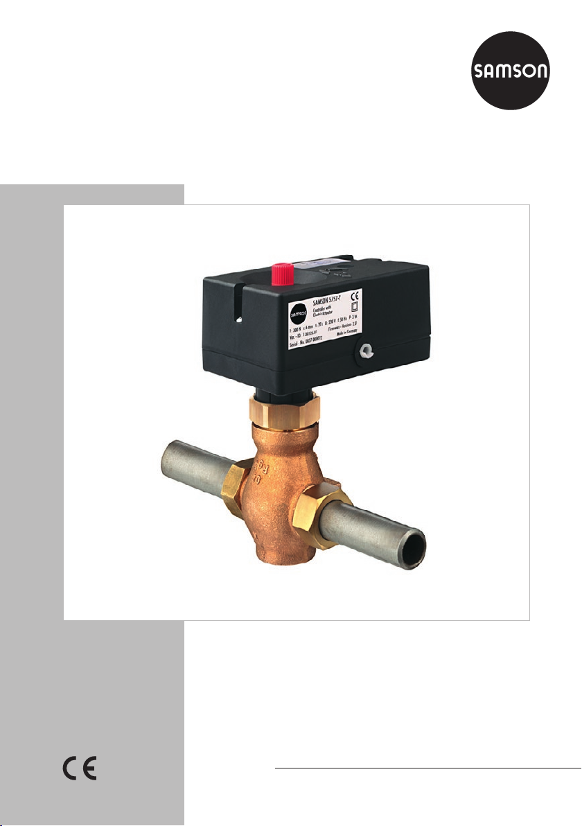
TROVIS5757-7 Electric Actuator with
Process Controller
For heating and cooling applications
Translation of original instructions
Mounting and
Operating Instructions
EB 5757-7 EN
Firmware version 2.04
Edition September 2016
Page 2
Note on these mounting and operating instructions
These mounting and operating instructions assist you in mounting and operating the device
safely. The instructions are binding for handling SAMSON devices.
Î For the safe and proper use of these instructions, read them carefully and keep them for
later reference.
Î If you have any questions about these instructions, contact SAMSON‘s After-sales Service
Department (aftersalesservice@samson.de).
The mounting and operating instructions for the devices are included in
the scope of delivery. The latest documentation is available on our website
(www.samson.de) > Product documentation. You can enter the document
number or type number in the [Find:] eld to look for a document.
Denition of signal words
!
DANGER
Hazardous situations which, if not avoided,
will result in death or serious injury
!
WARNING
Hazardous situations which, if not avoided,
could result in death or serious injury
2 EB 5757-7 EN
!
NOTICE
Property damage message or malfunction
Note
Additional information
Tip
Recommended action
Page 3

Contents
1 Safety instructions and measures ...................................................................5
1.1 Notes on possible severe personal injury .........................................................8
1.2 Notes on possible property damage ................................................................9
2 Markings on the device ...............................................................................10
2.1 Actuator nameplate ......................................................................................10
2.2 Valve nameplate ..........................................................................................10
3 Design and principle of operation ................................................................11
3.1 Operating controls .......................................................................................12
3.1.1 LEDs ...........................................................................................................12
3.2 LED blinking pattern .....................................................................................12
3.2.1 Handwheel ..................................................................................................14
3.2.2 Travel indicator ............................................................................................14
3.3 Accessories .................................................................................................14
3.4 Technical data .............................................................................................15
3.5 Dimensions in mm ........................................................................................16
4 Measures for preparation ............................................................................18
4.1 Unpacking ..................................................................................................18
4.2 Transporting and lifting ................................................................................18
4.2.1 Transporting ................................................................................................18
4.2.2 Lifting ..........................................................................................................18
4.3 Storage .......................................................................................................18
5 Mounting and start-up .................................................................................19
5.1 Mounting the actuator onto the valve .............................................................19
5.2 Installing the control valve into the pipeline ....................................................19
5.3 Electrical connections ...................................................................................19
5.4 Conguring the electric actuator ....................................................................20
6 Operation ...................................................................................................23
6.1 Manually changing the stem position .............................................................23
7 Servicing.....................................................................................................24
7.1 Preparation for return shipment .....................................................................24
8 Malfunctions ...............................................................................................24
EB 5757-7 EN 3
Page 4

Contents
8.1 Emergency action ........................................................................................24
9 Decommissioning and disassembly ..............................................................24
9.1 Decommissioning .........................................................................................25
9.2 Removing the actuator from the valve ............................................................26
9.3 Disposal ......................................................................................................26
10 Appendix ....................................................................................................26
10.1 After-sales service ........................................................................................26
10.2 Conguration list and customer settings .........................................................27
10.2.1 Customer setting ..........................................................................................29
10.3 Resistance values with Pt 1000 resistors .........................................................30
10.4 EU declaration of conformity .........................................................................31
4 EB 5757-7 EN
Page 5

Safety instructions and measures
1 Safety instructions and measures
The TROVIS5757-7 Electric Actuator with Process Controller is an electric actuator with an
integrated digital controller. It is designed for operating a mounted globe valve. In combina-
tion with the valve, the actuator is used to control the ow of liquids or vapors in the pipeline.
The electric actuator with process controller is suitable for closed-loop operation in heating
and cooling applications.
The actuator is designed to operate under exactly dened conditions (e.g. thrust, travel).
Therefore, operators must ensure that the actuator is only used in applications that meet the
specications used for sizing the actuator at the ordering stage. In case operators intend to
use the actuator in other applications or conditions than specied, SAMSON must be con-
tacted.
SAMSON does not assume any liability for damage resulting from the failure to use the de-
vice for its intended purpose or for damage caused by external forces or any other external
factors.
Î Refer to the technical data for limits and elds of application as well as possible uses. See
section3.4.
Reasonably foreseeable misuse
The actuator is not suitable for the following applications:
− Use outside the limits dened during sizing and in the technical data
Furthermore, the following activities do not comply with the intended use:
− Use of non-original spare parts
− Performing service and repair work not described in these instructions
Qualications of operating personnel
The actuator must be mounted, started up, serviced, and repaired by fully trained and qualied personnel only; the accepted industry codes and practices are to be observed. According to these mounting and operating instructions, trained personnel refers to individuals who
are able to judge the work they are assigned to and recognize possible hazards due to their
specialized training, their knowledge and experience as well as their knowledge of the appli-
cable standards.
EB 5757-7 EN 5
Page 6

Safety instructions and measures
Personal protective equipment
No personal protective equipment is required for the direct handling of the electric actuator
with process controller. Work on the valve on which the electric actuator is mounted may be
necessary when mounting or removing the actuator from the valve.
Î Observe the requirements for personal protective equipment specied in the valve docu-
mentation.
Î Check with the plant operator for details on further protective equipment.
Revisions and other modications
Revisions, conversions or other modications to the product are not authorized by SAMSON.
They are performed at the user's own risk and may lead to safety hazards, for example. Fur-
thermore, the product may no longer meet the requirements for its intended use.
Safety features
None
Warning against residual hazards
The electric actuator with process controller has a direct inuence on the valve when it is
mounted on the valve. To avoid personal injury or property damage, plant operators and
operating personnel must prevent hazards that could be caused in the control valve by the
process medium, the operating pressure, the signal pressure or by moving parts by taking
appropriate precautions. They must observe all hazard statements, warning and caution
notes in these mounting and operating instructions, especially for installation, start-up, and
maintenance.
Responsibilities of the operator
The operator is responsible for proper operation and compliance with the safety regulations.
Operators are obliged to provide these mounting and operating instructions as well as the
referenced documents to the operating personnel and to instruct them in proper operation.
Furthermore, the operator must ensure that operating personnel or third persons are not exposed to any danger.
Responsibilities of operating personnel
Operating personnel must read and understand these mounting and operating instructions as
well as the referenced documents and observe the specied hazard statements, warning and
caution notes. Furthermore, the operating personnel must be familiar with the applicable
health, safety and accident prevention regulations and comply with them.
6 EB 5757-7 EN
Page 7

Safety instructions and measures
Referenced standards and regulations
The electric actuator with process controller fullls the requirements of the Directives
2014/30/EU and 2014/35/EU. The declaration of conformity includes information about
the applied conformity assessment procedure. This declaration of conformity is included in
the Appendix of these instructions.
The electric actuator with process controller is designed for use in low voltage installations.
Î For wiring, maintenance, and repair, observe the relevant safety regulations.
Referenced documentation
The following documents apply in addition to these mounting and operating instructions:
− Conguration Manual uKH5757-7 for TROVIS5757-7 Electric Actuator with Process
Controller (detailed description of all functions and parameters)
− Mounting and operating instructions of the valve on which the electric actuator is mount-
ed, e.g. for SAMSON valves:
uEB3135-1 for Type2488 Pressure-independent Control Valve (PICV)
uEB3136 for Type2488N Pressure-independent Control Valve (PICV)
uEB5861 for Type3260 Three-way Valve
uEB5863 for Type3226 Three-way Valve
uEB5866 for Type3222 Globe Valve
uEB5867 for Type3222N Globe Valve
uEB5868 for Type3213 Globe Valve
EB 5757-7 EN 7
Page 8

Safety instructions and measures
1.1 Notes on possible severe personal injury
!
DANGER
Risk of electric shock.
Î Before connecting wiring, performing any work on the device or opening the de-
vice, disconnect the power supply and protect it against unintentional reconnection.
Î Only use power interruption devices that are protected against unintentional recon-
nection of the power supply.
Î Do not open the back housing cover.
The electric actuators with process controllers are protected against dripping water fall-
ing at an angle (IP42).
Î Avoid contact with spray water or water jets.
The switching output L' is live after the power supply has been connected.
Î Do not touch the switching output L'.
Risk of bursting in pressure equipment.
Control valves and pipelines are pressure equipment. Improper opening can lead to
valve components bursting.
Î Before starting any work on the control valve, depressurize all plant sections con-
cerned as well as the valve.
Î Drain the process medium from all the plant sections concerned and from the valve.
Î Wear recommended personal protective equipment. See associated valve docu-
mentation.
8 EB 5757-7 EN
Page 9

Safety instructions and measures
1.2 Notes on possible property damage
!
NOTICE
Risk of actuator damage due to the power supply exceeding the permissible tolerances.
The electric actuators are designed for use according to regulations for low-voltage
installations.
Î Observe the permissible tolerances of the power supply.
Risk of actuator damage due to excessively high tightening torques.
The connection of the electric actuator must be tightened with certain torques. Excessively tightened torques lead to parts wearing out quicker.
Î Observe the specied tightening torques.
Malfunction due to a conguration that does not meet the requirements of the application.
The electric actuator with process controller is congured for the specic application by
setting conguration items and parameters.
Î Perform the conguration for the specic application during start-up and after a re-
set to default settings.
EB 5757-7 EN 9
Page 10

Markings on the device
2 Markings on the device
2.1 Actuator nameplate
TROVIS 5757-7
Electric Actuator
with Process Controller
Var.-ID xxxxxxx Serial no. xxxx *xxxxxx*
F: 300 N Firmware: 2.xx
U: 230 V f: 50 Hz P: 3 VA Made in Germany
F Thrust
s Rated travel
v Stroking speed
U Power supply
f Power line frequency
P Power consumption
2.2 Valve nameplate
s: 6 mm v: 0.3 mm/s
See associated valve documentation.
10 EB 5757-7 EN
Page 11

Design and principle of operation
182
1.1
182
1.1
3 Design and principle of oper-
ation
The TROVIS5757-7 Electric Actuator with
Process Controller is a combination of a linear actuator and an integrated digital controller. The combination is especially designed for heating applications as well as for
xed set point control of heating systems in
small to medium-sized buildings. It is partic-
ularly suitable for mounting to SAMSON
Types3222, 3222N, 2488 and 3267
Valves (DN15 to 25) as well as to special
versions of Type3226 and Type3260
Valves.
The digital controller is connected to a ow
sensor on the input side, which can be op-
tionally upgraded by a return ow, outdoor
or room sensor. In addition to the Pt1000
input, the digital controller has a potentiome-
ter input (1000 to 1100Ω or 1000 to 2000
Ω) to measure the ow temperature. This input inuences the heating characteristic in
the case of outdoor-temperature-controlled
control and the room temperature set point
in the case of xed set point control with
room temperature inuence. The heating
characteristic and set point can be changed
over the TROVIS-VIEW conguration software.
The output signal of the integrated digital
controller acts over the positioner on the synchronous motor of the actuator and is transferred over the connected gear to the actuator stem (3) and used as the positioning
force.
The motor is switched off by torque-dependent switches when an end position is
reached or in case the motor is overloaded.
The actuator is mounted onto the valve using
a coupling nut (4).
When the actuator stem extends, the valve is
closed, opposing the force of the valve
spring (7). When the actuator stem retracts,
the valve is opened as the plug stem (6) follows the motion of the return spring.
retracted
Actuator stem
extended
3
4
7
6
1 Electric actuator
with process
controller
1.1
Connecting cable 6 Plug stem
2 Handwheel (only
use when power is
disconnected)
3 Actuator stem
Fig.1: Functional diagram
4 Coupling nut
5 Travel indicator
7 Valve spring
8 Cover, serial
5
interface
connection,
slider switch,
and LEDs
5
EB 5757-7 EN 11
Page 12

Design and principle of operation
ON
OFF
Time [s]
ON
OFF
Time [s]
ON
OFF
Time [s]
The valve can be moved to any position in
the de-energized state by the handwheel
(2). Travel and direction of action can be
read off the travel indicator (5) on the side of
the actuator housing.
Slider switch
Slider switch (red)
Fig.2: Position of the slider switch
The slider switch allows you to switch be-
tween two different congurations #1 and
#2. In position #1, the slider switch points
away from the housing and in position #2
towards the middle of the housing. In both
levels #1 and #2, the functions described in
section10.2 can be activated and the asso-
ciated parameter settings made. The default
settings is the same for both levels #1 and
#2, except for function block F13. Changes
to functions and parameters can be made
over the TROVIS-VIEW software.
The position of the slider switch determines
which function and parameter settings (level
#1 or #2) is used for closed-loop operation.
3.1 Operating controls
3.1.1 LEDs
3.2 LED blinking pattern
The device has a red and a yellow LED
which indicate the operating states of the actuator.
The LEDs are located underneath the cover
on top of the circuit board.
Blinking pattern of the yellow LED
− Actuator switched off or command mode
− Actuator switched on or memory pen
action completed
− Active return ow temperature limitation
or plausibility error in memory pen
12 EB 5757-7 EN
Page 13

Design and principle of operation
ON
OFF
Time [s]
ON
OFF
Time [s]
ON
OFF
Time [s]
ON
OFF
Time [s]
ON
OFF
]
ON
OFF
Time [s]
ON
OFF
Time [s]
ON
OFF
Time [s]
ON
OFF
Time [s]
ON
OFF
Time [s]
− Preparing to read data from memory
pen
− Preparing to write data to memory pen
− Preparing data logging
− Data logging in progress
Blinking pattern of the red LED
− Device switched off, normal operation or
command mode
− Device start-up or torque-dependent limit
switch error
− Exceptional error or sensor line break-
age
− EEPROM error in device
− EEPROM error in memory pen
− Zero calibration
Time [s
EB 5757-7 EN 13
Page 14

Design and principle of operation
ON
OFF
Time [s]
OFF
ON
Time [s]
ON
OFF
Time [s]
ON
OFF
Time [s]
ON
OFF
Time [s]
− Internal transit time measurement
− Flow sensor defective
− Outdoor/room sensor defective
− Return ow sensor defective
− Potentiometer defective
3.2.2 Travel indicator
Travel and direction of action can be read
off the travel indicator (5, Fig.1) on the side
of the actuator housing.
3.3 Accessories
Accessories for communication
The TROVIS-VIEW software is required for the TROVIS5757-7 Electric Actuator with Process Controller. The
TROVIS-VIEW software can be downloaded free of charge from our website (u www.samson.de > Services >
Software > TROVIS-VIEW). The software can
also be supplied on a CD-ROM. Further details can be found in Data Sheet uT6661.
Accessories for heating and cooling applications
− Type5267-2 Contact Sensor (Pt1000)
Conguration ID: 1058683
Permissible temperatures:
Medium –20 to 120°C
Ambient –20 to 120°C
Degree of protection IP42
3.2.1 Handwheel
The valve can be moved to any position in
the de-energized state by the handwheel (2,
Fig.1).
14 EB 5757-7 EN
Page 15

Design and principle of operation
− Type5257-7 Room Panel (Pt1000) with
potentiometer and mode selector switch
Conguration ID: 1180319
Permissible temperatures:
Medium –20 to 60°C
Ambient –20 to 60°C
− Type5227-2 Outdoor Sensor (Pt1000)
Conguration ID: 1043862
Permissible temperatures:
Medium –35 to 85°C
Ambient –35 to 85°C
Degree of protection IP44
Degree of protection IP30
3.4 Technical data
TROVIS5757-7 Electric Actuator with Process Controller
Temperature sensor Max. 3 x Pt1000
Operating temperature range –40 to 150°C
Binary inputs
1)
(instead of potentiometer) Floating contact, contact load 5V/1mA
BI1
1)
(instead of return ow
BI2
sensor)
Potentiometer input 1000 to 1100 Ω or 1000 to 2000 Ω
Switching output 230V/50Hz/1A
Rated travel 6mm
Transit time for rated travel 20s
Thrust 300N
Power supply 230V (±10%)/50Hz
Power consumption 5VA
Class of protection II
Permissible temperatures
Ambient 0 to 50°C
Storage –20 to 70°C
Degree of protection IP42
Mounting position Any position except suspended
Electromagnetic compatibility According to EN61000-6-2, EN61000-6-3 and EN61326
Compliance
Weight Approx. 0.7kg
2)
Floating contact, contact load 5V/1mA
Circulation pump or external demand
·
1)
Recommendation: use devices with gold contacts when using relays.
2)
The permissible medium temperature depends on the valve on which the electric actuator with
process controller is mounted. The limits in the valve documentation apply.
EB 5757-7 EN 15
Page 16

Design and principle of operation
Ø 12
80
eL Stem retracts
aL Stem extends
3.5 Dimensions in mm
11
55
32 70
114
70
2.5 m
Fig.3: TROVIS5757-7 Electric Actuator with Process Controller
16 EB 5757-7 EN
Page 17

50
36
75
28
82 32
20
32
60
Ø4
22
21
Type5227-2 Outdoor Sensor (Pt1000)
Conguration ID: 1043862
Color: RAL 9016
50
Design and principle of operation
30
2
Type5267-2 Contact Sensor (Pt1000)
(ow and return ow temperature
measurement)
Conguration ID: 1058683
Type5257-7 Room Panel (Pt1000)
Conguration ID: 1180319
Color: Cover and knobs RAL 9016 · Base RAL 7047
Continuous day mode (rated operation)
86
Continuous night mode (reduced operation)
Off/frost protection
Fig.4: Accessories for heating applications
EB 5757-7 EN 17
Page 18

Measures for preparation
4 Measures for preparation
After receiving the shipment, proceed as follows:
1. Check the scope of delivery. Compare
the shipment received against the delivery note.
2. Check the shipment for transportation
damage. Report any damage to
SAMSON and the forwarding agent (refer to delivery note).
4.1 Unpacking
Information
Do not remove the packaging until immediately before mounting and start-up.
1. Remove the packaging from the electric
actuator.
2. Dispose of the packaging in accordance
with the valid regulations.
4.2 Transporting and lifting
4.2.1 Transporting
− Protect the electric actuator against exter-
nal inuences (e.g. impact).
− Protect the electric actuator against mois-
ture and dirt.
− Observe the permissible transportation
temperature of –20 to +70°C.
4.2.2 Lifting
Due to the low service weight, lifting equipment is not required to lift the electric actuator.
4.3 Storage
!
NOTICE
Risk of actuator damage due to improper
storage.
− Observe storage instructions.
− Avoid long storage times.
− Contact SAMSON in case of different stor-
age conditions or long storage periods.
Information
We recommend regularly checking the electric actuator and the prevailing storage conditions during long storage periods.
Storage instructions
− Protect the electric actuator against exter-
nal inuences (e.g. impact).
− Protect the electric actuator against mois-
ture and dirt.
− Make sure that the ambient air is free of
acids or other corrosive media.
− Observe the permissible storage tem-
perature from –20 to +70°C.
− Do not place any objects on the electric
actuator.
18 EB 5757-7 EN
Page 19

Mounting and start-up
5 Mounting and start-up
!
NOTICE
Risk of malfunction due to incorrectly performed start-up.
Perform start-up following the described
sequence.
5.1 Mounting the actuator onto the valve
!
NOTICE
Risk of actuator damage due to excessively
high tightening torques.
Observe the specied tightening torques.
The actuator has a force-locking connection
to the valve in de-energized state.
Î Turn the handwheel (2, Fig.1 on
page11) counterclockwise to retract
the actuator stem as far as it will go.
Î Place the actuator on the valve con-
nection and tighten the coupling nut
(Fig.1 on page11) (tightening torque
20Nm).
5.2 Installing the control valve into the pipeline
!
NOTICE
Degree of protection not achieved due to incorrect mounting position.
Do not install the valve with the actuator
suspended downwards.
Î Install the valve into the pipeline accord-
ing the specications in the mounting
and operating instructions of the valve.
5.3 Electrical connections
!
DANGER
Risk of electric shock.
− Upon installation of the electric cables, you
are required to observe the regulations
concerning low-voltage installations according to DINVDE0100 as well as the
regulations of your local power supplier.
− Use a suitable power supply which guar-
antees that no dangerous voltages reach
the device in normal operation or in the
event of a fault in the system or any other
system parts.
− Connect the actuator to the electrical net-
work only after the power supply is rst
switched off. Make sure the power cannot
be switched on unintentionally.
− The switching output L' is live. Do not touch
the switching output L'.
The actuator requires a Pt1000 temperature
sensor (e.g. Type5267-2) to be connected to
measure the ow temperature.
Depending on the control task, an outdoor
sensor (e.g. Type5227-2) or room panel
(Type5257-7 only) can be connected. They
can all be combined with a return ow sensor (e.g. Type5267-2).
Additionally, the actuator has a potentiome-
ter input 1000 to 1100Ω (e.g. Type5257-
7) or 1000 to 2000Ω. This input is used to
correct the room set point (±5K) in case of
EB 5757-7 EN 19
Page 20

Mounting and start-up
xed set point control with room temperature
inuence (uKH5757-7). On using an out-
door sensor, it can change the adjusted heating characteristic (uKH5757-7). The
non-oating switching output can alternatively be used as an output for an external
demand for heat.
The connected sensors are monitored for line
breakages. A fault in the line of a sensor is
indicated by the red LED blinking (underneath the cover on top of the circuit board).
Each sensor has its own blinking pattern (see
section3.2). In the event that several sensors
are defective, the LED blinks using the sequence for the sensor with the highest priority:
Highest priority Flow sensor
Outdoor sensor or
room sensor
Return ow sensor
Lowest priority Potentiometer
The actuator stem extends and the red and
yellow LEDs are illuminated located under
the cover on top of the circuit board.
As soon as the actuator stem has reached
the nal position, the red LED is turned off.
The yellow LED remains illuminated and indicates that the actuator is ready for use.
5.4 Conguring the electric actuator
The actuator is congured with the
TROVIS-VIEW software. All the functions and
parameters are listed in section10.2.
Information
The Conguration Manual uKH5757-7
can be found in the Help menu of the
TROVIS-VIEW software. The manual contains a detailed description of each function
and parameter.
Example: In the event that the ow sensor
and outdoor sensor are defective, the LED
initially blinks to indicate that the ow sensor
is defective. When this fault is eliminated, the
LED then blinks to indicate that the outdoor
sensor is defective.
Î Perform the electrical connection depend-
ing on the heating application according
to one of the following wiring diagrams
(Fig.5 to Fig.7). As soon as the actuator
is connected to the power supply, the ini-
tialization procedure starts.
20 EB 5757-7 EN
Page 21

Mounting and start-up
1L
1L
VS
Pt 1000
Pt 1000
OG YE RD BN BK GN BN BU BK
ASRüS
Pt 1000
34 652
100/
1000 Ω
1000 Ω
230 V,
50 Hz
L´N
!
DANGER
Live wires
Application with ow sensor (VS), return ow sensor (RüS) and outdoor sensor (AS)
and potentiometer functioning as set point adjuster
VS
BE2
Pt 1000
AS
Pt 1000
34 652
100/
1000 Ω
230 V,
1000 Ω
50 Hz
L´N
OG YE RD BN BK GN BN BU BK
!
DANGER
Live wires
Application with ow sensor (VS), outdoor sensor (AS), binary input (BI2) to switch between
operating mode and potentiometer for adjusting the set point
OG Orange BN Brown BN Brown
YE Yellow BK Black BU Blue
RD Red GN Green BK Black
Fig.5: Electrical connections Note! Terminals at point of installation not included in the
scope of delivery.
EB 5757-7 EN 21
Page 22

Mounting and start-up
1L
1L
VS
Pt 1000
Pt 1000
OG YE RD BN BK GB BN BU BK
AS BE1RüS
Pt 1000
34 652
230 V,
50 Hz
L´N
!
DANGER
Live wires
Application with ow sensor (VS), return ow sensor (RüS), outdoor sensor (AS) and
binary input (BI1) to switch between operating modes
VS
BE2 BE1
Pt 1000
AS
Pt 1000
34 652
230 V, 50 Hz
L´N
OG YE RD BN BK GN BN BU BK
!
DANGER
Live wires
Application with ow sensor (VS) and outdoor sensor (AS)
OG Orange BN Brown BN Brown
YE Yellow BK Black BU Blue
RD Red GN Green BK Black
Fig.6: Electrical connections Note! Terminals at point of installation not included in the
scope of delivery.
22 EB 5757-7 EN
Page 23

Operation
1L
VS
OG YE RD BN BK GN BN BU BK
Fig.7: Electrical connections Note! Terminals at point of installation not included in the
6 Operation
RüS
Pt 1000
Pt 1000
2
Application with ow sensor (VS), return ow sensor (RüS) and room sensor with
Type5257-7 Room Panel
1432
34 65
mode selector switch and set point adjuster
230 V,
scope of delivery.
50 Hz
L´N
!
Live wires
The stem position is changed at the hand-
DANGER
wheel:
Immediately after completing mounting and
start-up, the valve with electric actuator is
ready for use.
Î Switch off the power supply.
Î Turn clockwise to extend the actuator
stem (approx. 4 turns for 1mm travel).
6.1 Manually changing the stem position
Î Turn counterclockwise to retract the actu-
ator stem (approx. 4 turns for 1mm trav-
el).
The stem must only be manually positioned
when the power supply is switched off as the
stem position is determined by the process
controller in closed-loop operation, meaning
any manual adjustment would be automatically corrected.
EB 5757-7 EN 23
Page 24

Servicing
7 Servicing
Information
The electric actuator with process controller
was checked by SAMSON before it left the
factory.
− The product warranty becomes void if ser-
vice or repair work not described in these
instructions is performed without prior
agreement by SAMSON's After-sales Service department.
− Only use original spare parts by
SAMSON, which comply with the original
specications.
7.1 Preparation for return shipment
Defective electric actuators can be returned
to SAMSON for repair.
Proceed as follows to return valves to
SAMSON:
1. Put the control valve out of operation and
remove it from the pipeline. See associated valve documentation.
2. Remove the electric actuator from the
valve. See section9.2.
3. Send the electric actuator to your nearest
SAMSON subsidiary. SAMSON subsidiaries are listed on our website at
uwww.samson.de > Contact.
8 Malfunctions
Î Troubleshooting (see Table1).
Information
Contact SAMSON's After-sales Service department for malfunctions not listed in the table.
8.1 Emergency action
The plant operator is responsible for emergency action to be taken in the plant.
Tip
Emergency action in the event of valve failure is described in the associated valve documentation.
9 Decommissioning and disas-
sembly
!
!
DANGER
DANGER
Risk of electric shock.
− Before performing any work on the device
and before opening the device, disconnect
the power supply and protect it against unintentional reconnection.
− Only use power interruption devices that
are protected against unintentional reconnection of the power supply.
24 EB 5757-7 EN
Page 25

Decommissioning and disassembly
!
!
DANGER
DANGER
Risk of bursting in control valve components
due to incorrect opening.
− Before starting any work on the control
valve, depressurize all plant sections concerned and the valve.
− Drain the process medium from all the
plant sections concerned and from the
valve.
− Wear recommended personal protective
equipment. See associated valve documentation.
9.1 Decommissioning
To decommission the electric actuator for
maintenance work or disassembly, proceed
as follows:
1. Close the shut-off valves upstream and
downstream of the control valve to stop
the process medium from owing
through the valve.
2. Completely drain the pipelines and
valve.
3. Disconnect and lock the power supply.
4. If necessary, allow the pipeline and valve
components to cool down.
5. Remove the valve from the pipeline. See
associated valve documentation.
Table1: Troubleshooting
Error Possible reasons Recommended action
Actuator or plug stem does not
move on demand.
Actuator is blocked. Check attachment.
Unblock the actuator.
No or incorrect power supply
connected.
Check the power supply and
connections.
Actuator or plug stem does not
move through the whole range.
The electric actuator with process
controller does not perform the
functions as required.
No or incorrect power supply connected.
The conguration of the electric
actuator does not meet the
application requirements.
The electric actuator was reset to
its default settings without adapting
the conguration to the application
afterwards.
Check the power supply and
connections.
Check conguration.
If necessary, refer to the
Conguration Manual
uKH5757-7.
EB 5757-7 EN 25
Page 26

Appendix
9.2 Removing the actuator from the valve
1. Undo the coupling nut (4) and remove
the actuator from the valve connection.
9.3 Disposal
Î Observe local, national, and internation-
al refuse regulations.
Î Do not dispose of components, lubri-
cants, and hazardous substances together with your other household waste.
10 Appendix
10.1 After-sales service
Contact SAMSON's After-sales Service department for support concerning service or
repair work or when malfunctions or defects
arise.
E-mail
You can reach the After-sales Service Department at aftersalesservice@samson.de.
Addresses of SAMSONAG and its subsidiaries
The addresses of SAMSON AG, its subsidiaries, representatives, and service facilities
worldwide can be found on the SAMSON
website, in all SAMSON product catalogs or
on the back of these Mounting and Operating Instructions.
Required specications
Please submit the following details:
− Order number and position number in
the order
− Type, serial number, rmware version,
device version
26 EB 5757-7 EN
Page 27

Appendix
10.2 Conguration list and customer settings
Conguration list
There are separate two levels #1 and #2. Both levels contain the functions F01 to F13 with
the specied default settings and meanings.
The functions F01 to F13 have the following listed functions.
F = Function WE = Default setting 0 = OFF, 1 = ON
F Function WE Meaning
01 Control mode 1 0 – Fixed set point control
1 – Control with reference variable
02 Selecting the reference variable
(only effective when F01 - 1)
03 Direction of stem action 0 0 – Increasing/increasing >>
04 Delayed outdoor temperature
(only effective when F01 - 1 and
F02 - 0)
05 Potentiometer input 0 0 – Not active (binary input)
06 Resistance range of potentiometer
(only effective when F05 - 1)
07 Function of potentiometer (only ef-
fective when F02 - 0 and F05 - 1)
08 Function of binary input BI1 (only
effective when F05 - 0)
0 0 – Outdoor sensor
1 – Room sensor
1 – Increasing/decreasing <>
0 0 – Without delay
1 – With delay
1 – Active
0 0 – Type 5257-7 Room Panel (1000 to 1100 ohm)
1 – Remote adjuster (1000 to 2000ohm)
0 0 – Heating characteristic level shift
1 Gradient shift
0 0 BI1 short-circuited: OFF with frost protection
1 BI1 short-circuited: Reduced operation
09 Function of switching output 0 0 – BO as circulation pump control
1 – BO as heat demand (ON in rated operation)
10 Anti-block protection of pumps
(only effective when F09 - 0)
11 Return ow temperature sensor 1 0 – Inactive, binary input 2 active
12 Function of binary input BI2 (only
effective when F11 - 0)
1 0 – No anti-block protection
1 – When pumps are deactivated: switched on
every 24h for 1min
1 – Active, with return ow temperature limitation
0 0 – BI2 short-circuited: OFF with frost protection
1 – BI2 short-circuited: Reduced operation
EB 5757-7 EN 27
Page 28

Appendix
F Function WE Meaning
13 Manual mode 0
1)
0 – Inactive
1 – Manual mode (absolute priority)
Parameter list
There are separate two parameter levels #1 and #2. Both parameter levels contain the functions P01 to P23 with the specied default settings and setting ranges.
The parameters have the setting ranges as listed below.
P = Parameter WE = Default setting
P
Parameters WE
01 Flow temperature set point 70°C 0 to 150°C
02 Flow temperature set-back in reduced operation 15K 0 to 50K
03 Min. ow temperature 20°C 0 to 150°C
04 Max. ow temperature 120°C 0 to 150°C
05 Heating characteristic gradient 1.6 0.2 to 3.2
06 Heating characteristic level 0K –30 to 30K
07 Gradient shift range via potentiometer 1.0 0.0 to 1.5
08 Level shift range via potentiometer 15K 0 to 30K
09 Kp ow temperature control 2.0 0.1 to 50.0
10 Tn ow temperature control 120 s 0 to 999 s
11 Ty actuator transit time for valve travel 24 s 10 to 240 s
12 Dead band (switching range) 2.0% 0.5 to 5.0%
13 Max. return ow temperature 50°C 10 to 90°C
14 Kp return ow temperature limitation 1.0 0.1 to 50.0
15 Tn return ow temperature limitation 400 s 0 to 999 s
16 Delay time for outdoor temperature 3.0°C/h 1.0 to 6.0°C/h
17 Outdoor temperature limit value at rated operation 22°C 0 to 50°C
18 Outdoor temperature limit value at reduced operation 15°C 0 to 50°C
19 Room temperature set point at rated operation 20°C 10 to 40°C
20 Room temperature set point at reduced operation 15°C 10 to 40°C
Adjustment
range
28 EB 5757-7 EN
Page 29

Appendix
P
Parameters WE
21 Max. room temperature boost for switch-off 2K 1 to 6K
22 Time interval for ash adaptation 10 min 0 to 100 min
23 Pump lag time 5 min 1 to 999 min
Adjustment
range
10.2.1 Customer setting
Station
Operator
SAMSON ofce
Function blocks Parameters
Performed setting Performed setting
F WE #1 #2 P WE #1 #2 Adjustment range
01 1 01 70°C 0 to 150°C
02 0 02 15K 0 to 50K
03 0 03 20°C 0 to 150°C
04 0 04 120°C 0 to 150°C
05 0 05 1.6 0.2 to 3.2
06 0 06 0K –30 to 30K
07 0 07 1.0 0.0 to 1.5
08 0 08 15K 0 to 30K
09 0 09 2.0 0.1 to 50.0
10 1 10 120 s 0 to 999 s
11 1 11 24 s 10 to 240 s
12 0 12 2.0% 0.5 to 5.0%
13 0
1)
13 50°C 10 to 90°C
EB 5757-7 EN 29
Page 30

Appendix
Function blocks Parameters
Performed setting Performed setting
F WE #1 #2 P WE #1 #2 Adjustment range
1)
The default setting F13 - 1 ap-
plies for level #2.
14 1.0 0.1 to 50.0
15 400 s 0 to 999 s
16 3.0°C/h 1.0 to 6.0°C/h
17 22°C 0 to 50°C
18 15°C 0 to 50°C
19 20°C 10 to 40°C
20 15°C 10 to 40°C
21 2K 1 to 6K
22 10 min 0 to 100 min
23 5 min 1 to 999 min
10.3 Resistance values with Pt 1000 resistors
°C –35 –30 –25 –20 –15 –10 –5 0 5 10
Ω 862.5 882.2 901.9 921.6 941.2 960.9 980.4
°C 15 20 25 30 35 40 45 50 55 60
Ω
1058.5 1077.9 1097.3 1116.7 1136.1 1155.4 1174.7 1194.0 1213.2 1232.4
°C 65 70 75 80 85 90 95 100 105 110
Ω
1251.6 1270.7 1289.8 1308.9 1328.0 1347.0 1366.0 1385.0 1403.9 1422.9
°C 115 120 125 130 135 140 145 150
Ω
1441.7 1460.6 1479.4 1498.2 1517.0 1535.8 1554.5 1573.1
1000.0 1019.5 1039.0
30 EB 5757-7 EN
Page 31

10.4 EU declaration of conformity
EU Konformitätserklärung/EU Declaration of Conformity
Für das folgende Produkt/For the following product
Kombinierter Regler mit Hubantrieb / Controller with Electric Actuator
wird die Konformität mit den nachfolgenden EU-Richtlinien bestätigt/signifies compliance with the
following EU Directives:
EMC 2004/108/EC (bis/to 2016-04-19)
EMC 2014/30/EU (ab/from 2016-04-20)
LVD 2006/95/EC (bis/to 2016-04-19)
LVD 2014/35/EU (ab/from 2016-04-20)
Hersteller/Manufacturer:
Frankfurt, 2016-04-06
Typ / Type 5757
EN 61000-6-2:2005, EN 61000-6-3:2010
EN 60730-1:2011, EN 61010-1:2010
SAMSON AKTIENGESELLSCHAFT
D-60314 Frankfurt am Main
Deutschland/Germany
Weismüllerstraße 3
Appendix
Gert Nahler ppa. Günther Scherer
Zentralabteilungsleiter/Head of Departm ent Qualitätssicherung/Quality Managment
Entwicklung Automation und Integrationstechnologien/
Development Automation and Integration Technologies
EB 5757-7 EN 31
Page 32

SAMSON AG · MESS- UND REGELTECHNIK
Weismüllerstraße 3 · 60314 Frankfurt am Main, Germany
Phone: +49 69 4009-0 · Fax: +49 69 4009-1507
samson@samson.de · www.samson.de
EB 5757-7 EN
2018-05-17 · English
 Loading...