

Page 1

Mounting and
Operating Instructions
EB 5724 EN
Firmware version 2.20
Edition August 2016
Translation of original instructions
Electric Actuators with Process Controllers
TROVIS5724-3 (without fail-safe action)
TROVIS5725-3 (with fail-safe action)
for domestic hot water heating
Page 2
2 EB 5724 EN
Note on these mounting and operating instructions
These mounting and operating instructions assist you in mounting and operating the device
safely. The instructions are binding for handling SAMSON devices.
Î For the safe and proper use of these instructions, read them carefully and keep them for
later reference.
Î If you have any questions about these instructions, contact SAMSON‘s After-sales Service
Department (aftersalesservice@samson.de).
The mounting and operating instructions for the devices are included in
the scope of delivery. The latest documentation is available on our website
(www.samson.de) > Product documentation. You can enter the document
number or type number in the [Find:] eld to look for a document.
Denition of signal words
Hazardous situations which, if not avoided,
will result in death or serious injury
Hazardous situations which, if not avoided,
could result in death or serious injury
Property damage message or malfunction
Additional information
Recommended action
DANGER
!
WARNING
!
NOTICE
!
Note
Tip
Page 3

Contents
EB 5724 EN 3
1 Safety instructions and measures ...................................................................5
1.1 Notes on possible severe personal injury .........................................................8
1.2 Notes on possible personal injury ...................................................................9
1.3 Notes on possible property damage ................................................................9
2 Markings on the device ...............................................................................10
2.1 Actuator nameplate ......................................................................................10
2.2 Valve nameplate ..........................................................................................10
3 Design and principle of operation ................................................................11
3.1 Fail-safe positions ........................................................................................12
3.2 Operating controls .......................................................................................12
3.3 Accessories .....................................................................................................
3.4 Technical data .............................................................................................15
3.5 Dimensions in mm ........................................................................................17
4 Measures for preparation ............................................................................20
4.1 Unpacking ..................................................................................................20
4.2 Transporting and lifting ................................................................................20
4.2.1 Transporting ................................................................................................20
4.2.2 Lifting ..........................................................................................................20
4.3 Storage .......................................................................................................20
4.4 Aligning the travel indication scale ................................................................21
5 Mounting and start-up ................................................................................. 21
5.1 Mounting the actuator onto the valve .............................................................21
5.1.1 Force-locking attachment ..............................................................................21
5.1.2 Form-t attachment ......................................................................................22
5.2 Installing the control valve into the pipeline ....................................................22
5.3 Electrical connections ...................................................................................22
5.4 Conguring the electric actuator ....................................................................24
5.5 Quick check ................................................................................................24
6 Operation ...................................................................................................27
6.1 Manually changing the stem position .............................................................27
Page 4

4 EB 5724 EN
Contents
7 Servicing.....................................................................................................29
7.1 Preparation for return shipment .....................................................................29
8 Malfunctions ...............................................................................................30
8.1 Emergency action ........................................................................................30
9 Decommissioning and disassembly ..............................................................30
9.1 Decommissioning .........................................................................................30
9.2 Removing the actuator from the valve ............................................................31
9.2.1 Force-locking attachment ..............................................................................31
9.2.2 Form-t attachment ......................................................................................31
9.3 Disposal ......................................................................................................31
10 Appendix ....................................................................................................31
10.1 After-sales service ........................................................................................31
10.2 Conguration and parameter list ...................................................................32
10.3 Parameter list ...............................................................................................33
10.4 Customer setting ..........................................................................................34
10.5 EU declaration of conformity .........................................................................35
Firmware revisions
2.11
(old)
2.13 (new)
Additional setting option 'Circulation pump (heating) reversed' in Function of switching
output (F16). See section10.2 and uKH 5724.
2.13
(old)
2.20 (new)
New pump protection function (F17). See section10.2 and uKH 5724.
Page 5

EB 5724 EN 5
Safety instructions and measures
1 Safety instructions and measures
The TROVIS5724-3 and TROVIS5725-3 Electric Actuators with Process Controllers are a
combination of an electric actuator and an integrated digital controller. They are designed
for operating a mounted globe valve. In combination with the valve, the actuator is used to
control the ow of liquids in the pipeline. The electric actuators with process controllers are
suitable for DHW heating applications.
The actuator is designed to operate under exactly dened conditions (e.g. thrust, travel).
Therefore, operators must ensure that the actuator is only used in applications that meet the
specications used for sizing the actuator at the ordering stage. In case operators intend to
use the actuator in other applications or conditions than specied, SAMSON must be con-
tacted.
SAMSON does not assume any liability for damage resulting from the failure to use the de-
vice for its intended purpose or for damage caused by external forces or any other external
factors.
Î Refer to the technical data for limits and elds of application as well as possible uses. See
section3.4.
Reasonably foreseeable misuse
The actuator is not suitable for the following applications:
− Use outside the limits dened during sizing and in the technical data
Furthermore, the following activities do not comply with the intended use:
− Use of non-original spare parts
− Performing service and repair work not described in these instructions
Qualications of operating personnel
The actuator must be mounted, started up, serviced, and repaired by fully trained and qualied personnel only; the accepted industry codes and practices are to be observed. According to these mounting and operating instructions, trained personnel refers to individuals who
are able to judge the work they are assigned to and recognize possible hazards due to their
specialized training, their knowledge and experience as well as their knowledge of the appli-
cable standards.
Page 6

6 EB 5724 EN
Safety instructions and measures
Personal protective equipment
No personal protective equipment is required for the direct handling of the electric actuator
with process controller. Work on the valve on which the electric actuator is mounted may be
necessary when mounting or removing the actuator from the valve.
Î Observe the requirements for personal protective equipment specied in the valve docu-
mentation.
Î Check with the plant operator for details on further protective equipment.
Revisions and other modications
Revisions, conversions or other modications to the product are not authorized by SAMSON.
They are performed at the user's own risk and may lead to safety hazards, for example. Fur-
thermore, the product may no longer meet the requirements for its intended use.
Safety features
The following safety features exist:
− Upon power supply failure, the TROVIS5725-3 Electric Actuator causes the valve to
move to a certain fail-safe position. The fail-safe action of SAMSON actuators is speci-
ed on the actuator nameplate.
Warning against residual hazards
To avoid personal injury or property damage, plant operators and operating personnel must
prevent hazards that could be caused in the control valve by the process medium, the operating pressure, the signal pressure or by moving parts by taking appropriate precautions. They
must observe all hazard statements, warning and caution notes in these mounting and operating instructions, especially for installation, start-up, and maintenance.
Responsibilities of the operator
The operator is responsible for proper operation and compliance with the safety regulations.
Operators are obliged to provide these mounting and operating instructions to the operating
personnel and to instruct them in proper operation. Furthermore, the operator must ensure
that operating personnel or third persons are not exposed to any danger.
Responsibilities of operating personnel
Operating personnel must read and understand these mounting and operating instructions as
well as the specied hazard statements, warning and caution notes. Furthermore, the operating personnel must be familiar with the applicable health, safety and accident prevention
regulations and comply with them.
Page 7

EB 5724 EN 7
Safety instructions and measures
Referenced standards and regulations
The electric actuators with process controllers comply with the requirements of the Directives
2014/30/EU and 2014/35/EU. The declaration of conformity includes information about
the applied conformity assessment procedure. This declaration of conformity is included in
the Appendix of these instructions.
The electric actuators are designed for use in low-voltage installations.
Î For wiring, maintenance, and repair, observe the relevant safety regulations.
Referenced documentation
The following documents apply in addition to these mounting and operating instructions:
− Conguration Manual for TROVIS5724-3 and TROVIS5725-3 Electric Actuators with
Process Controllers uKH5724
− Mounting and operating instructions of the valve on which the electric actuator is mount-
ed, e.g. for SAMSON valves:
uEB5861 for Type3260 Three-way Valve
uEB5863 for Type3226 Three-way Valve
uEB5866 for Type3222 Globe Valve
uEB5867 for Type3222N Globe Valve
uEB5868 for Type3213 and Type3214 Globe Valves
uEB8111 for Type3321 Globe Valve
uEB8113 for Type3323 Three-way Valve
uEB8131 for Type3531 Globe Valve for Heat Transfer Oil
uEB8135 for Type3535 Three-way Valve for Heat Transfer Oil
uEB3018 for Type42-36E Pressure-independent Control Valve (PICV) with electric ac-
tuator
Page 8

8 EB 5724 EN
Safety instructions and measures
1.1 Notes on possible severe personal injury
DANGER
!
Risk of electric shock.
Î Before connecting wiring, performing any work on the device or opening the de-
vice, disconnect the power supply and protect it against unintentional reconnection.
Î Only use power interruption devices that are protected against unintentional recon-
nection of the power supply.
Î Do not remove any covers to perform adjustment work on live parts.
Î Do not open the back housing cover.
The electric actuators with process controllers are protected against spray water
(IP54).
Î Avoid jets of water.
The switching output L' might be live after the supply voltage has been connected.
Î Do not touch the switching output L'.
Î When the switching output is not used, deactivate it in function F16 ('Passive' set-
ting).
Risk of bursting in pressure equipment.
Control valves and pipelines are pressure equipment. Improper opening can lead to
valve components bursting.
Î Before starting any work on the control valve, depressurize all plant sections con-
cerned as well as the valve.
Î Drain the process medium from all the plant sections concerned and from the valve.
Î Wear recommended personal protective equipment. See associated valve docu-
mentation.
Page 9

EB 5724 EN 9
Safety instructions and measures
1.2 Notes on possible personal injury
WARNING
!
Crush hazard arising from moving parts.
The form-t version of the electric actuator with process controller contains moving
parts (actuator and plug stems), which can injure hands or ngers if inserted into the
actuator.
Î Do not insert hands or nger into the yoke while the valve is in operation.
Î Disconnect the power supply before performing any work on the control valve.
Î Do not impede the movement of the actuator or plug stem by inserting objects into
their path.
1.3 Notes on possible property damage
NOTICE
!
Risk of actuator damage due to the power supply exceeding the permissible tolerances.
The electric actuators are designed for use according to regulations for low-voltage installations.
Î Observe the permissible tolerances of the power supply.
Risk of actuator damage due to excessively high tightening torques.
The connection of the electric actuator must be tightened with certain torques. Excessively tightened torques lead to parts wearing out quicker.
Î Observe the specied tightening torques.
Malfunction due to a conguration that does not meet the requirements of the application.
The electric actuator with process controller is congured for the specic application by
setting conguration items and parameters.
Î Perform the conguration for the specic application during start-up and after a re-
set to default settings.
Page 10
10 EB 5724 EN
Markings on the device
2 Markings on the device
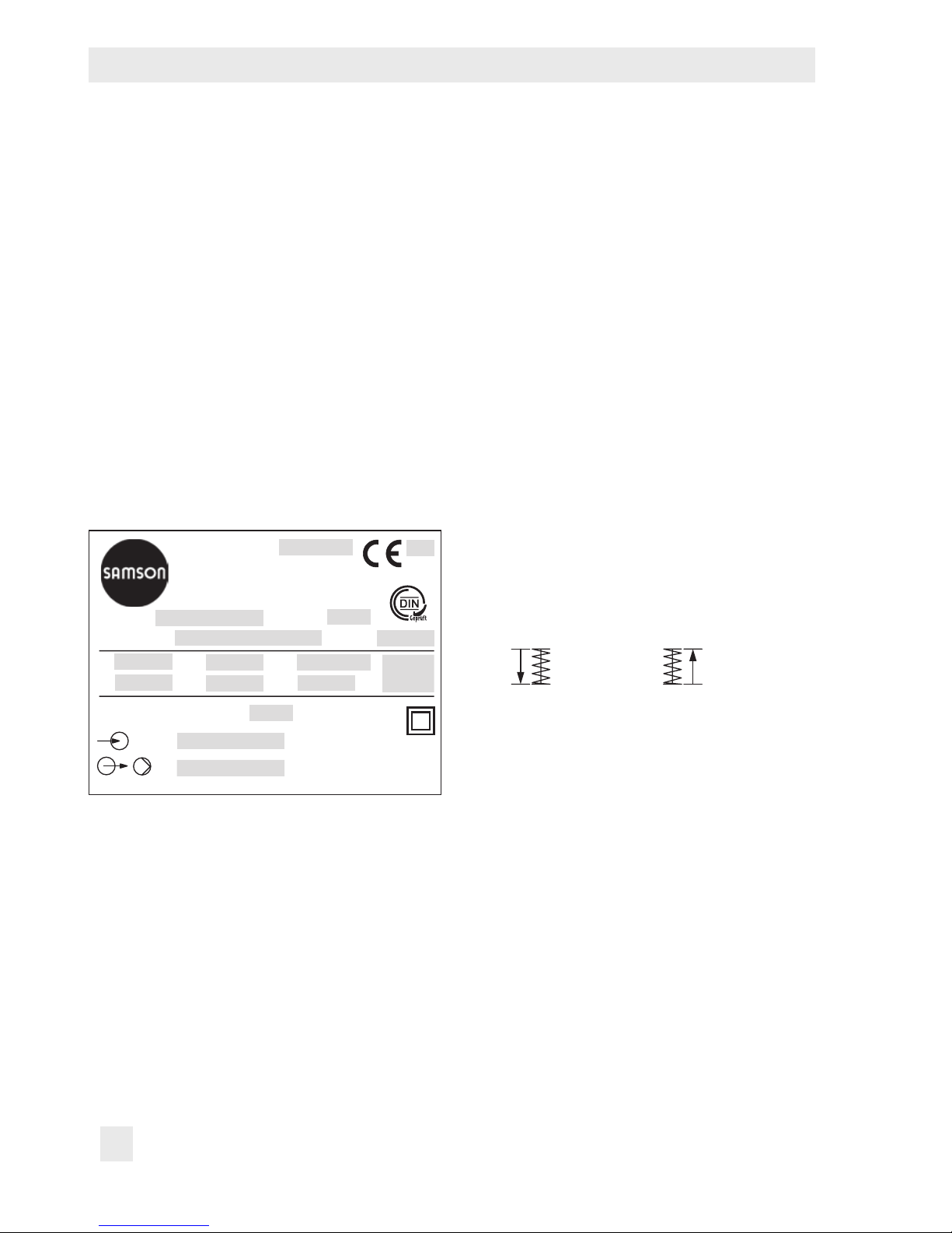
2.1 Actuator nameplate
1
2
Var.-ID
Serial no.
3
5
15
16
SAMSON
Controller with
Model
0062
4
6
F:
7
10
11
U:
f:
9
t:
12
P:
13
8
s:
Electric Actuator
Firmware - Version:
:
:
14
1 Type designation
2 Year of manufacture
3 Conguration ID
4 Model designation (TROVIS5725-3 only)
5 Serial number
6 DIN registration number (TROVIS5725-3
only)
7 Thrust
8 Rated travel
9 Transit time for rated travel
10 Power supply
11 Power line frequency
12 Power consumption
13 Fail-safe action (TROVIS5725-3 only)
Actuator
stem retracts
Actuator
stem extends
14 Firmware version
15 Inputs
16 Outputs
2.2 Valve nameplate
See associated valve documentation.
Risk of damage to the screw heads on the front cover due to the use of the wrong
tool.
The actuator housing cover is fastened using TORX PLUS
®
screws, size 10IP.
Î To loosen and tighten the screws, only use the following screwdrivers:
− TORX
®
T10
− TORX PLUS
®
10IP
− Flat-blade screwdriver with 0.8mm blade thickness and 4.0mm blade width
Page 11
EB 5724 EN 11
Design and principle of operation
3 Design and principle of oper-
ation
The TROVIS5724-3 and TROVIS5725-3
Electric Actuators with Process Controller
consist of a linear actuator with an integrat-
ed digital controller.
They are especially designed for DHW heat-
ing in instantaneous heating systems for
small to medium-sized buildings and for
xed set point control circuits in mechanical
engineering applications. They are particu-
larly suitable for mounting to SAMSON
Types3213, 3214, 3260, 3222, and 3226
Valves.
A special version of Type3222 (DN25) and
Type3222N DN15) with a special plug de-
sign is available for small installations
(apartment or house). As a result, even small
tapping amounts can be controlled.
The integrated digital controller must be connected to a temperature sensor on the input
side, which can be optionally upgraded by a
water ow sensor or a ow switch.
Alternatively, a current signal can be used
for mechanical engineering applications.
The set point of the digital controller is set
to 60°C and can be changed manually at
the set point potentiometer (11) or in the
TROVIS-VIEW software.
The actuator contains a reversible synchronous motor and a maintenance-free gear.
The synchronous motor is switched off by
torque-dependent switches in the end positions or in case of overload. The force of the
electric motor is transmitted via gearing and
crank disk to the actuator stem (3) and to the
plug stem of the mounted valve.
0
100
50
891 1.1212 1.2
11
0
6
12
15
15
12
6
0
0
6
12
15
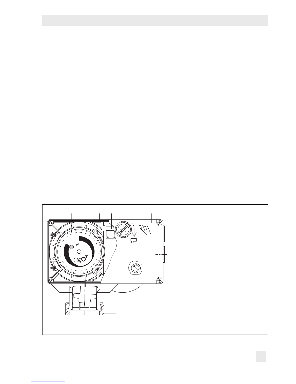
3
1 Electric actuator with process
controller
1.1 Front cover
1.2 Cable entry
2 Handwheel (TROVIS5724-3 only)
3 Actuator stem
4 Coupling nut
8 Spring assembly (TROVIS5725-3
only)
9 Travel indication scale
11 Set point potentiometer
12 Serial interface (RJ-12 port)
Î Do not open the back housing cover.
Fig.1: TROVIS5724-3 and 5725-3 Electric Actuators with Process Controller, force-locking valve
connection
Page 12

12 EB 5724 EN
Design and principle of operation
When the actuator stem extends, it presses
on the plug stem (10) of the valve. When the
actuator stem retracts, the plug stem follows
the movement of the return spring in the
valve.
Actuator and valve are connected by the
coupling nut (4).
TROVIS 5724-3
The electric actuator without fail-safe action
has a handwheel (2) used to manually position the valve (only when the actuator is disconnected from the power supply). Travel
and direction of action can be read off the
travel indication scale (9).
TROVIS 5725-3
The electric actuator with fail-safe action
contains a spring assembly (8) and an electromagnet, which move the connected valve
to its fail-safe position when de-energized.
Î The fail-safe action must not be used to
control the valve position.
The TROVIS 5725-3 Electric Actuator
with Process Controller with "actuator
stem extends" fail-safe action is tested by
the German Technical Inspectorate (TÜV)
according to DIN EN 14597 in combination
with various SAMSON valves. The register
number is available on request.
3.1 Fail-safe positions
TROVIS5724-3
The TROVIS5724-3 Electric Actuator with
Process Controller does not have fail-safe action. When a valve is mounted on this actuator, the valve remains in the last position after the power supply fails.
TROVIS5725-3
The TROVIS5725-3 Electric Actuator with
Process Controller has fail-safe action. When
a valve is mounted on this actuator, the valve
is moved to the fail-safe position specied on
the nameplate (12 in Fig.1) after the power
supply fails:
− Actuator stem extends: upon power sup-
ply failure, the actuator stem extends.
− Actuator stem retracts: upon power sup-
ply failure, the actuator stem retracts.
3.2 Operating controls
Travel indicator
Handwheel
Fig.2: Operating controls on the actuator
Page 13

EB 5724 EN 13
Design and principle of operation
Travel indicator
Travel and direction of action can be read
off the scale of the travel indicator.
The scale must be turned when a three-way
mixing valve is used so that the travel and
scale reading match. See section4.4.
Handwheel (TROVIS5724-3 only)
The valve position can be changed manually
using the handwheel. See section6.1.
LEDs
The device has a red and a yellow LED
which indicate the operating states of the device.
The LEDs are located underneath the front
cover on top of the circuit board.
Risk of damage to the screw heads on the
front cover due to the use of the wrong tool.
To loosen and tighten the screws, only use
TORX
®
T10, TORXPLUS®10IP, or a atblade screwdriver with 0.8mm blade thickness and 4.0mm blade width.
We recommend screwing the bottom screws
of the open housing front cover into the top
holes of the housing.
Blinking pattern of the yellow LED
− Device switched off or command mode
ON
OFF
Time [s]
− Device switched on or memory pen
action completed
ON
OFF
Time [s]
− Plausibility error in memory pen
ON
OFF
Time [s]
− Preparing to read data from memory
pen
ON
OFF
Time [s]
− Preparing to write data to memory pen
ON
OFF
Time [s]
− Preparing data logging
ON
OFF
Time [s]
Note
NOTICE
!
Tip
Page 14

14 EB 5724 EN
Design and principle of operation
− Data logging in progress
ON
OFF
Time [s]
− EEPROM error in memory pen
ON
OFF
Time [s]
Blinking pattern of the red LED
− Normal operation or memory pen insert-
ed
ON
OFF
Time [s]
− Device starting up
ON
OFF
Time [s]
− Temperature too high (upper limit (GWH)
exceeded)
ON
OFF
Time [s]
− EEPROM error in device
ON
OFF
Time [s]
− Zero calibration in progress
ON
OFF
Time [s]
− Internal transit time measurement
ON
OFF
Time [s]
− Wire breakage at temperature input
OFF
ON
Time [s]
− Wire breakage at current input
ON
OFF
Time [s]
− Flow rate at water ow sensor exceeds
measuring range
ON
OFF
Time [s]
Page 15

EB 5724 EN 15
Design and principle of operation
3.3 Accessories
Communication
− TROVIS-VIEW software (6661-1060) for
revision 2 of the TROVIS5724-3 and
TROVIS5725-3 Electric Actuator with
Process Controller is required. The
TROVIS-VIEW software can be downloaded free of charge from our website
(u www.samson.de at Services > Soft-
ware > TROVIS-VIEW). The software can
also be supplied on a CD-ROM. Further
details in Data Sheet u T6661.
− Hardware package
Accessories for data transmission (including memory pen-64, connecting cable and modular adapter), order no.
1400-9998
− Memory pen-64
For indirect data transmission, order no.
1400-9753
DHW heating in instantaneous heating
system
− Type5207-0060 Temperature Sensor,
optimized Pt1000 temperature sensor
with fast response which is simple to install
− Sensor pocket
For Type5207-0060 Pt1000 Sensor for
mounting to heat exchangers with G¾
for optimal positioning instantaneous
heating systems, order no. 1400-9249
− Water ow sensor
Axial turbine owmeter for liquids and
associated extension cable with mating
connector, order no. 1400-9246)
− Flow switch
To recognize when hot water is being
tapped using an NO contact
3.4 Technical data
Electric actuator with
process controller
TROVIS 5724 5725
-310 -313 -320 -323 -330 -333 -310 -313 -320 -323 -330 -333
Fail-safe action Without With
Operating direction – Extends
Rated travel mm 6 6 12 12 15 15 6 6 12 12 15 15
Transit time for rated travel s 35 18 70 36 90 45 35 18 70 36 90 45
Transit time for fail-safe action s – 4 4 6 6 7 7
Thrust N 700 500 280
Thrust in the event of fail-safe
action
N – 500 280
Attachment
Force-locking • • • • • • • •
Form-t • • • •
Handwheel Yes Possible
1)
Page 16

16 EB 5724 EN
Design and principle of operation
Electric actuator with
process controller
TROVIS 5724 5725
-310 -313 -320 -323 -330 -333 -310 -313 -320 -323 -330 -333
Fail-safe action Without With
Operating direction – Extends
Power supply 230V (±10%), 50Hz 230V (±10%), 50Hz
Power consumption Approx. VA 4 7.7 4 7.7 4 7.7 5.5 9.2 5.5 9.2 5.5 9.2
Permissible temperatures
5)
Ambient 0 to 50°C 0 to 50°C
Storage –20 to +70°C –20 to +70°C
Safety
Degree of protection IP54
4)
IP54
4)
Class of protection II (according to EN 61140)
Overvoltage category II (according to EN60664)
Degree of contamination 2 (according to EN60664)
Electromagnetic compatibility According to EN61000-6-2, EN61000-6-3 and EN61326
Vibration According to EN61000-6-2 and EN60068-2-27
Compliance
·
Inputs and outputs
Binary input BI1
3)
Floating contact for internal set point switchover or to deactivate the func-
tion to maintain the heat exchanger at a constant temperature
Binary input BI2
3)
Floating contact to connect a ow switch
Switching output 230V/50Hz, max. 1A
Weight kg (approx.) 1.1 1.3
Accessories
Temperature sensor Pt1000, fast response
Water ow sensor 530 pulses/l, measuring range 1 to 30l/min
Flow switch
2)
Yes · Alternative to water ow sensor
1)
Manual override using 4mm Allen key (after removing the front cover); actuator always returns to fail-safe position
after release.
2)
The ow switch or water ow sensor is not required in DHW heating in instantaneous systems with a constant circulation.
3)
Recommendation: use devices with gold contacts when using relays.
4)
Up to device index .03 only when the actuator is installed in the upright position. See last two gures of the conguration ID written on the nameplate (see page10), e.g. Var.-ID xxxxxxx.xx, for the device index.
5)
The permissible medium temperature depends on the valve on which the electric actuator with process controller is
mounted. The limits in the valve documentation apply.
Page 17

EB 5724 EN 17
Design and principle of operation
3.5 Dimensions in mm
TROVIS5724-313/-323
TROVIS5725-313/-323
12
18
Ø70
51
(33)
136
146
48 44
103
82
113
TROVIS5724-310/-320
TROVIS5725-310/-320
146
82
113
48 44
103
TROVIS5724-333
TROVIS5725-333
12
51
Ø10
46.5
6
18
Ø70
(33)
44
103
Page 18

18 EB 5724 EN
Design and principle of operation
Ø10
46.5
6
146
82
113
48
TROVIS5724-330
TROVIS5725-330
Type 5207-0060 Pt1000 Sensor
Time response: t
0.5
< 1s, t
0.9
< 3s; in
water 0.4m/s
PN 16
Max. medium temperature: 80°C
Accessories for domestic
hot water heating
Ø3.3
Ø5.4
10.5
15
52 ±1 2000
approx.
50
Water ow sensor with extension
cable
Order no. 1400-9246
Measuring range 1 to 30l/min,
DN10, PN10, IP54
max. medium temperature: 70°C
Extension cable length: 2m
50
G¾
G¾
13 13
Page 19

EB 5724 EN 19
Design and principle of operation
G¼
G¾
35
G¾
65
G¼
G¾
35
G¾
65
G¼
G1
35
G¾
65
38
G¾
G¾
39
G1
G¾
Sensor pocket (including gasket)
for heat exchanger with G¾
Order no. 1400-9249
Connecting piece (including
gasket) for valve G¾
Order no. 1400-9236
Circulation pipe connection
(including gasket)
Order no. 1400-9232
Sensor pocket (including gasket)
for heat exchanger with G1
Order no. 1400-9252
Connecting piece (including
gasket) for valve G1
Order no. 1400-9237
Page 20

20 EB 5724 EN
Measures for preparation
4 Measures for preparation
After receiving the shipment, proceed as follows:
1. Check the scope of delivery. Compare
the shipment received against the delivery note.
2. Check the shipment for transportation
damage. Report any damage to
SAMSON and the forwarding agent (refer to delivery note).
4.1 Unpacking
Do not remove the packaging until immediately before mounting and start-up.
1. Remove the packaging from the electric
actuator.
2. Dispose of the packaging in accordance
with the valid regulations.
4.2 Transporting and lifting
4.2.1 Transporting
− Protect the electric actuator against exter-
nal inuences (e.g. impact).
− Protect the electric actuator against mois-
ture and dirt.
− Observe the permissible transportation
temperature of –20 to +70°C.
4.2.2 Lifting
Due to the low service weight, lifting equipment is not required to lift the electric actuator.
4.3 Storage
Risk of actuator damage due to improper
storage.
− Observe storage instructions.
− Avoid long storage times.
− Contact SAMSON in case of different stor-
age conditions or long storage periods.
We recommend regularly checking the electric actuator and the prevailing storage conditions during long storage periods.
Storage instructions
− Protect the electric actuator against exter-
nal inuences (e.g. impact).
− Protect the electric actuator against mois-
ture and dirt.
− Make sure that the ambient air is free of
acids or other corrosive media.
− Observe the permissible storage tem-
perature from –20 to +70°C.
− Do not place any objects on the electric
actuator.
Note
NOTICE
!
Note
Page 21

EB 5724 EN 21
Mounting and start-up
4.4 Aligning the travel
indication scale
The travel indication scale has two opposed
scales. Which scale is to be used depends
on the valve version (Fig.3). In the delivered
state, the scale alignment applies to globe
valves and three-way diverting valves. The
alignment needs to be changed when a
three-way mixing valve is used (see below).
0
0
6
6
12
15
12
15
0
15
12
6
Holes for
driving pin with three-
way mixing valve
Driving pin in position 0,
location of scale with globe or three-way
diverting valves (delivered state)
Fig.3: Travel indication scale
Globe and three-way diverting valves:
the driving pin is in position 0 (delivered
state).
Three-way mixing valve:
change the alignment of the scale
Risk of damage to the screw heads on the
front cover due to the use of the wrong tool.
To loosen and tighten the screws, only use
TORX
®
T10, TORXPLUS®10IP, or a atblade screwdriver with 0.8mm blade thickness and 4.0mm blade width.
Î Open front cover.
Î Remove scale, turn it and replace it so
that the pin is positioned over the appropriate hole (6, 12 or 15) corresponding
to the rated travel (6, 1 or 15mm travel).
Î Close front cover.
5 Mounting and start-up
Risk of malfunction due to incorrectly performed start-up.
Perform start-up following the described
sequence.
5.1 Mounting the actuator onto
the valve
The actuator is mounted either directly onto
the valve or using a rod-type yoke depend-
ing on the valve version used (see Fig.4).
5.1.1 Force-locking attach-
ment
1. Retract actuator stem:
− Using handwheel (TROVIS5724-3
only)
− Over manual level in TROVIS-VIEW
software
2. Place the actuator on the valve connec-
tion and tighten coupling nut (tightening
torque 20Nm).
NOTICE
!
NOTICE
!
Page 22

22 EB 5724 EN
Mounting and start-up
5.1.2 Form-t attachment
1. Place the actuator on the yoke (15) and
tighten the coupling nut (4) (tightening
torque 20Nm).
2. Place actuator with yoke (15) on the
valve and tighten the nut (17) (min. tight-
ening torque 150Nm).
3. Pull plug stem until it reaches the actuator stem or extend actuator stem using
the handwheel (2).
4. Position the clamps of the stem connector
(16) included in the accessories on the
ends of the actuator stem and plug stem
and screw tight.
5.2 Installing the control valve
into the pipeline
Degree of protection not achieved due to incorrect mounting position.
Do not install the valve with the actuator
suspended downwards (see Fig.5).
Î Install the valve into the pipeline accord-
ing the specications in the mounting
and operating instructions of the valve.
5.3 Electrical connections
Risk of electric shock.
− Upon installation of the electric cables, you
are required to observe the regulations
concerning low-voltage installations ac-
cording to DINVDE0100 as well as the
regulations of your local power supplier.
− Use a suitable power supply which guar-
antees that no dangerous voltages reach
the device in normal operation or in the
event of a fault in the system or any other
system parts.
− Connect the actuator to the electrical net-
work only after the power supply is rst
switched off. Make sure the power cannot
be switched on unintentionally.
− The switching output L' may be live. Do not
touch the switching output L'.
The electric actuator requires a fast-response
Pt1000 sensor to be connected for it to function.
Two set points W1 and W2 can be used.
The binary input BI1 is used to switch between the set points.
In addition, a water ow sensor or a ow
switch can be connected to quickly recognize
when hot water is being tapped.
Alternatively, instead of the Pt1000 sensor,
the current input 0/4 to 20mA can be used
for control purposes in mechanical engineering applications.
The connected temperature sensor and the
current input congured as 4 to 20mA are
monitored for line breakages.
A wire breakage of a sensor is indicated by
the red LED blinking slowly. It cannot be de-
tected when a 0 to 20mA input signal is
used.
NOTICE
!
DANGER
!
Page 23

EB 5724 EN 23
Mounting and start-up
3
4
0
0
2
15
4
16
17
Force-locking attachment with coupling nut, e.g.
to Type3222 Valve
Form-t attachment with stem connector, e.g. with
rod-type yoke on Series V2001 Valve
2 Handwheel (TROVIS5724-3 only)
3 Actuator stem
4 Coupling nut
15 Yoke
16 Stem connector
17 Nut
Fig.4: Attaching actuator and valve Fig.5: Mounting position
Page 24

24 EB 5724 EN
Mounting and start-up
Risk of damage to the screw heads on the
front cover due to the use of the wrong tool.
To loosen and tighten the screws, only use
TORX
®
T10, TORXPLUS®10IP, or a atblade screwdriver with 0.8mm blade thickness and 4.0mm blade width.
Î Open front cover.
Î Guide the connecting cables through the
cable gland.
Î Perform the electrical connection de-
pending on the application according to
one of the following wiring diagrams
(Fig.6 and Fig.7).
As soon as the actuator is connected to
the power supply, zero calibration starts.
The actuator stem extends (when the direction of action increasing/increasing
has been set) and the red and yellow
LEDs under the serial interface are illuminated.
As soon as the actuator stem has
reached the nal position, the red LED is
turned off.
The yellow LED remains illuminated and
indicates that the actuator is ready for
use.
Î Close front cover.
5.4 Conguring the electric
actuator
Change the conguration items and parameters in the TROVIS-VIEW software. All the
conguration items and parameters are list-
ed in the appendix.
All conguration items and parameters are
described in detail in the associated conguration manual uKH 5724. This conguration manual can be downloaded from the
SAMSON website (www. samson.de) and is
available in the [?] menu in the
TROVIS-VIEW software.
1. Perform the application-specic congu-
ration in TROVIS-VIEW. See documentation on TROVIS-VIEW software
uEB6661.
2. Transfer the conguration to the electric
actuator using the connecting cable or
memory pen.
3. We recommend writing down the cong-
uration made in section10.4.
NOTICE
!
Tip
Page 25

EB 5724 EN 25
Mounting and start-up
1)
LL'
N5
VINS1 SS2
230V, 50Hz
3)
4)
BE1
LL'
N5
VINS1 SS2
230V, 50Hz
3)
4)
BE2
2)
4)
LL'
N5
VINS1 SS2
230V, 50Hz
3)
LL'
N5
VINS1 SS2
230V, 50Hz
+–0(4) ... 20mA
3)
4)
LL'
N5
VINS1 SS2
230V, 50Hz
+–0(4) ... 20mA
3)
4)
LL'
N5
VINS1 SS2
230V, 50Hz
3)
4)
Operation with Pt1000 sensor
DHW heating in instantaneous heating system
Mechanical engineering applications
Operation with Pt1000 sensor
and ow switch
Operation with Pt1000 sensor and set
point guided by current input
1)
Water ow sensor
2)
Flow switch
3)
Pump or fault alarm output
4)
Electromagnet (TROVIS5725-3 only)
Operation with current input
Operation with Pt1000 sensor and binary
contact to switch between set points
Operation with Pt1000 sensor and water
ow sensor
(see Fig.7 for information for connection of
water ow sensor)
DANGER *
!
Live wires
DANGER *
!
DANGER *
!
DANGER *
!
DANGER *
!
DANGER *
!
DANGER *
!
Fig.6: Electrical connections
Page 26

26 EB 5724 EN
Mounting and start-up
18:9
20
150
BK
GN
WH
BN
GN WH
BN
GN
WH
50
PVC 3 x 0.5 mm²
~ Ø125
Wire end ferrule
Plug connector
Nameplate
Cable tie
Bushing
Connection of water ow sensor (WWS)
BN Brown
GN Green
BK Black
WH White
Fig.7: Connection of water ow sensor (WWS)
Connection of water ow sensor (WWS)
WSS Extension cable TROVIS5724-3
GND BK BN
Signal GN GN IN
5V
WH
WH 5V
Page 27

EB 5724 EN 27
Operation
5.5 Quick check
To test the electric actuator's ability to function, the following quick checks can be performed:
Î Apply the maximum and minimum con-
trol signals (e.g. over the manual level in
TROVIS-VIEW).
Î Check the end positions of the valve.
Î Check the travel indication on the scale.
TROVIS 5725-3
Î Disconnect the power supply and check
whether the valve moves to the fail-safe
position.
6 Operation
Immediately after completing mounting and
start-up, the valve with electric actuator is
ready for use.
Form-t version: crush hazard arising from
moving parts (actuator and plug stem).
Do not insert hands or nger into the yoke
while the valve is in operation.
Form-t version: operation disturbed by a
blocked actuator or plug stem.
Do not impede the movement of the actuator
or plug stem by inserting objects into their
path.
6.1 Manually changing the
stem position
TROVIS5724-3 only
A manual adjustment of the stem position
only makes sense when the power supply is
switched off as the stem position is determined by the actuator in closed-loop operation, meaning any manual adjustment would
be automatically corrected by the actuator.
The stem position is changed at the handwheel:
Î Switch off the power supply.
Î Turn clockwise to extend the actuator
stem (approx. 4 turns for 1mm travel).
WARNING
!
NOTICE
!
Page 28

28 EB 5724 EN
Operation
Î Turn counterclockwise to retract the actu-
ator stem (approx. 4 turns for 1mm travel).
Changing the set point W1
The default settings of set point W1 is 60°C
and W2 is 70°C.
These set point can be changed in the TRO-
VIS-VIEW software.
To manually adjust the W1 set point without
TROVIS-VIEW, turn the set point potentiometer (11 in Fig.1) located on the printed cir-
cuit board of the actuator. The adjustable
setting range is between 10 and 100% of
the measuring range (default: lower measur-
ing range value Xmin = 0°C and upper
measuring range value Xmax = 100°C).
In the delivered state, the set point potenti-
ometer is set to 0%, i.e. it does not have any
effect on W1 set point (60°C).
Additional points that apply:
Device with rmware 2.10 or lower:
Î The set point potentiometer only takes ef-
fect when the actual value originates
from a Pt1000 sensor. In the combination with F05 - 1 (Current input active)
and F06 - 1 (Current input function = set
point), the set point potentiometer is not
active.
Device with rmware 2.11 or higher:
The set point can be adjusted even when using the current input.
Î The manually adjusted value at the set
point potentiometer for W1 is only used
for control if function block F12 in
TROVIS-VIEW is set to 1 (Automatic set
point potentiometer: manual setting ef-
fective above 10%. The required setting
F12 - 1 is the default setting.
Î The set point W2 can only be changed
in TROVIS-VIEW.
Risk of damage to the screw heads on the
front cover due to the use of the wrong tool.
To loosen and tighten the screws, only use
TORX
®
T10, TORXPLUS®10IP, or a atblade screwdriver with 0.8mm blade thickness and 4.0mm blade width.
1. Open front cover.
2. Set W1 set point as required at the set
point potentiometer (11 in Fig.1).
0
100
50
Setting range: 0 to
100% of the measuring range (default set-
ting 0 to 100°C)
Do not forget to check the automatic set
point potentiometer function.
3. Close front cover.
Function of automatic set point potentiometer
Î Any setting below 10% at the set point
potentiometer is ignored by the control-
ler. The controller uses the W1 set point
from the parameter list (TROVIS-VIEW
software) for control.
Î Any setting above 10% at the set point
potentiometer is used by the controller
NOTICE
!
Page 29

EB 5724 EN 29
Servicing
for control. The W1 set point entered in
TROVIS-VIEW is ignored.
7 Servicing
The electric actuator with process controller
was checked by SAMSON before it left the
factory.
− The product warranty becomes void if ser-
vice or repair work not described in these
instructions is performed without prior
agreement by SAMSON's After-sales Service department.
− Only use original spare parts by
SAMSON, which comply with the original
specications.
7.1 Preparation for return shipment
Defective electric actuators can be returned
to SAMSON for repair.
Proceed as follows to return valves to
SAMSON:
1. Put the control valve out of operation and
remove it from the pipeline. See associated valve documentation.
2. Remove the electric actuator from the
valve. See section9.2.
3. Send the electric actuator to your nearest
SAMSON subsidiary. SAMSON subsidiaries are listed on our website at
uwww.samson.de > Contact.
Note
Table1: Troubleshooting
Error Possible reasons Recommended action
Actuator or plug stem does not
move on demand.
Actuator is blocked. Check attachment.
Unblock the actuator.
No or incorrect power supply connected.
Check the power supply and
connections.
Actuator or plug stem does not
move through the whole range.
No or incorrect power supply connected.
Check the power supply and
connections.
The electric actuator with process
controller does not perform the
functions as required.
The conguration of the electric
actuator does not meet the
application requirements.
Check conguration.
If necessary, refer to the Con-
guration Manual
uKH5724.
The electric actuator was reset to
its default settings without adapting the conguration to the application afterwards.
Page 30

30 EB 5724 EN
Malfunctions
8 Malfunctions
Troubleshooting (see Table1).
Contact SAMSON's After-sales Service department for malfunctions not listed in the table.
8.1 Emergency action
The valve, on which the electric actuator with
fail-safe action is mounted, is moved to its
fail-safe position upon power supply failure
(see section3.1).
The plant operator is responsible for emergency action to be taken in the plant.
Emergency action in the event of valve
failure is described in the associated valve
documentation.
9 Decommissioning and disas-
sembly
Risk of electric shock.
− Before performing any work on the device
and before opening the device, disconnect
the power supply and protect it against unintentional reconnection.
− Only use power interruption devices that
are protected against unintentional reconnection of the power supply.
Risk of bursting in control valve components
due to incorrect opening.
− Before starting any work on the control
valve, depressurize all plant sections concerned and the valve.
− Drain the process medium from all the
plant sections concerned and from the
valve.
− Wear recommended personal protective
equipment. See associated valve documentation.
9.1 Decommissioning
To decommission the electric actuator for
maintenance work or disassembly, proceed
as follows:
1. Close the shut-off valves upstream and
downstream of the control valve to stop
the process medium from owing through
the valve.
2. Completely drain the pipelines and
valve.
3. Disconnect and lock the power supply.
4. If necessary, allow the pipeline and valve
components to cool down.
5. Remove the valve from the pipeline. See
associated valve documentation.
Note
Tip
DANGER
!
DANGER
!
DANGER
!
DANGER
!
Page 31

EB 5724 EN 31
Appendix
9.2 Removing the actuator
from the valve
9.2.1 Force-locking attach-
ment
1. Undo the coupling nut (4) and remove
the actuator from the valve connection.
9.2.2 Form-t attachment
1. Unscrew the stem connector clamps (16)
between the actuator stem and the plug
stem.
2. Undo the nut (17) and remove the rod-
type yoke (15) together with the actuator
from the valve.
3. Undo the coupling nut (4) and remove
the actuator from the rod-type yoke (15).
9.3 Disposal
Î Observe local, national, and internation-
al refuse regulations.
Î Do not dispose of components, lubri-
cants, and hazardous substances together with your other household waste.
10 Appendix
10.1 After-sales service
Contact SAMSON's After-sales Service department for support concerning service or
repair work or when malfunctions or defects
arise.
E-mail
You can reach the After-sales Service Department at aftersalesservice@samson.
Addresses of SAMSONAG and its subsidiaries
The addresses of SAMSON AG, its subsidiaries, representatives, and service facilities
worldwide can be found on the SAMSON
website, in all SAMSON product catalogs or
on the back of these Mounting and Operating Instructions.
Required specications
Please submit the following details:
− Order number and position number in
the order
− Type, serial number, rmware version,
device version
Page 32

32 EB 5724 EN
Appendix
10.2 Conguration and parameter list
Conguration list
The function blocks F01 to F14 have the following listed functions.
F = Function block WE = Default setting 0 = OFF, 1 = ON
F Function WE Meaning
01 DHW tapping recognition 1 0 – Continuous control
1 – Flow rate sensor active
02 Flow rate sensor 1 0 – Flow switch
1 – Water ow sensor
03 Adaptation 1 0 – Passive
1 – Active (with water ow sensor)
04 Operating direction 0 0 – >> (increasing/increasing)
1 – <> (increasing/decreasing)
05 Current input 0 0 – Passive (binary input)
1 – Active
06 Function of current input 0 0 – Actual value
1 – Set point
07 Measuring range of
current input
0 0 – 0 to 20mA
1 – 4 to 20mA
08 Function of binary input 0 0 – Termination of maintaining heat exchanger at constant
temperature
1 – Switchover between internal set points
09 Maintain heat exchanger
at constant temperature
0 0 – Time adjustable
1 – Continuous
10 Upper limit (GWH) 0 0 – No limitation
1 – Exceeding GWH causes switch-off
11 Lower limit (GWL) 0 0 – No frost protection
1 – Violation of GWL causes frost protection to start
12 Manual set point 1 0 – No manual adjustment
1 – Manual adjustment effective above 10%
16 Function of switching
output
3 1 – Passive
2 – Fault alarm
3 – Circulation pump (DHW)
4 – Circulation pump (heating)
5 – Tapping
6 – Circulation pump (heating) reversed
17 Pump protection 1 0 – No
1 – Yes
Page 33

EB 5724 EN 33
Appendix
10.3 Parameter list
The parameters have the setting ranges as listed below.
P = Parameter WE = Default setting
P Parameters WE Adjustment range
01 Set point W1 60°C 0 to 100°C
02 Set point W2 70°C 0 to 100°C
03 Lower measuring range value Xmin 0°C –50 to 90°C
04 Upper measuring range value Xmax 100°C 10 to 150°C
05 Upper limit (GWH) 95°C 0 to 100°C
06 Lower limit (GWL) 5°C 0 to 20°C
07 Proportional-action coefcient KP 0.6 0.1 to 50
08 Reset time Tn 25s 0 to 999s
09 Derivative-action time Tv 0s 0 to 999s
10 Actuator transit time Ty 35s 0 to 240s
11 Set-back difference 8K 0 to 30K
12 Heating period to maintain heat exchanger at
constant temperature
24h 0.0 to 25.5h
Page 34

34 EB 5724 EN
Appendix
10.4 Customer setting
Station
Operator
SAMSON ofce
Function blocks Parameters
F WE Performed setting P WE Performed setting Adjustment range
01 1 01 60°C 0 to 100°C
02 1 02 70°C 0 to 100°C
03 1 03 0°C –50 to 90°C
04 0 04 100°C 10 to 150°C
05 0 05 95°C 0 to 100°C
06 0 06 5°C 0 to 20°C
07 0 07 0.6 0.1 to 50
08 0 08 25s 0 to 999s
09 0 09 0s 0 to 999s
10 0 10 35s 0 to 240s
11 0 11 8K 0 to 30K
12 1 12 24h 0.0 to 25.5h
16 3
17 1
Page 35

EB 5724 EN 35
Appendix
10.5 EU declaration of conformity
SAMSON AKTIENGESELLSCHAFT
Weismüllerstraße 3 60314 Frankf urt am Main
Telefon: 069 4009-0 · Tel efax: 069 4009-1507
E-Mail: samson@samson .de
Revison 05
EU Konformitätserklärung/EU Declaration of Conformity
Für das folgende Produkt/For the following product
Kombinierter Regler mit Hubantrieb / Controller with Electric Actuator
Typ / Type 5724
wird die Konformität mit den nachfolgenden EU-Richtlinien bestätigt/signifies compliance with the
following EU Directives:
EMC 2004/108/EC (bis/to 2016-04-19)
EMC 2014/30/EU (ab/from 2016-04-20)
EN 61000-6-2:2005, EN 61000-6-3:2010
LVD 2006/95/EC (bis/to 2016-04-19)
LVD 2014/35/EU (ab/from 2016-04-20)
EN 60730-1:2011, EN 61010-1:2010
Hersteller/Manufacturer:
SAMSON AKTIENGESELLSCHAFT
Weismüllerstraße 3
D-60314 Frankfurt am Main
Deutschland/Germany
Frankfurt, 2016-04-06
Gert Nahler ppa. Günther Scherer
Zentralabteilungsleiter/Head of Department Qualitätssicherung/Quality Managment
Entwicklung Automation und Integrationstechnologien/
Development Automation and Integration Technologies
Page 36

SAMSON AG · MESS- UND REGELTECHNIK
Weismüllerstraße 3 · 60314 Frankfurt am Main, Germany
Phone: +49 69 4009-0 · Fax: +49 69 4009-1507
samson@samson.de · www.samson.de
EB 5724 EN
2016-11-01 · English
 Loading...