

Page 1
TROVIS 5600 Automation System
TROVIS 5610
Heating and District Heating Controller
Mounting and
Operating Instructions
EB 5610 EN
®
Electronics from SAMSON
Firmware version 1.40
Edition December 2014
Page 2

Controller versions
The TROVIS 5610 Heating and District Heating Controller is available in two different versions:
• Compact version with one control circuit
• Standard version with two control circuits
Both versions are described in Mounting and Operating Instructions EB 5610 EN.
2 EB 5610 EN
Controller versions
!
DANGER!
indicates a hazardous situation which, if not
avoided, will result in death or serious injury.
WARNING!
indicates a hazardous situation which, if not
avoided, could result in death or serious in
-
jury.
NOTICE
indicates a property damage message.
Note: Supplementary explanations, informa
-
tion and tips
Definitions of the signal words used in these instructions
Page 3

Contents Page
1 Safety instructions . . . . . . . . . . . . . . . . . . . . . . . . . . . 7
1.1 Start-up . . . . . . . . . . . . . . . . . . . . . . . . . . . . . . . . 7
1.2 Disposal . . . . . . . . . . . . . . . . . . . . . . . . . . . . . . . . 8
2 Operation . . . . . . . . . . . . . . . . . . . . . . . . . . . . . . . 9
2.1 Information menu . . . . . . . . . . . . . . . . . . . . . . . . . . . 11
2.1.1 Retrieving information . . . . . . . . . . . . . . . . . . . . . . . . . 12
2.2 Operation menu. . . . . . . . . . . . . . . . . . . . . . . . . . . . 14
2.2.1 Selecting the operating mode . . . . . . . . . . . . . . . . . . . . . 15
2.2.2 Defining special times-of-use . . . . . . . . . . . . . . . . . . . . . . 16
2.3 Times-of-use menu. . . . . . . . . . . . . . . . . . . . . . . . . . . 18
2.3.1 Changing the times-of-use . . . . . . . . . . . . . . . . . . . . . . . 18
3 Setup settings . . . . . . . . . . . . . . . . . . . . . . . . . . . . . 21
3.1 Changing set points and deactivation values . . . . . . . . . . . . . . 23
3.2 Altering the screen contrast or brightness . . . . . . . . . . . . . . . . 25
3.3 Changing the system date and time. . . . . . . . . . . . . . . . . . . 26
3.4 Calibrating the display. . . . . . . . . . . . . . . . . . . . . . . . . 27
3.5 Cleaning the display. . . . . . . . . . . . . . . . . . . . . . . . . . 28
3.6 Changing the language setting . . . . . . . . . . . . . . . . . . . . . 28
3.7 Configuring the controller and changing parameter settings . . . . . . . 29
3.7.1 Changing the system code number . . . . . . . . . . . . . . . . . . . 30
3.7.2 Activating or deactivating functions. . . . . . . . . . . . . . . . . . . 30
3.8 Setting parameters. . . . . . . . . . . . . . . . . . . . . . . . . . . 32
4 Manual mode . . . . . . . . . . . . . . . . . . . . . . . . . . . . . 33
5 Systems . . . . . . . . . . . . . . . . . . . . . . . . . . . . . . . . 35
6 Functions of the heating circuit. . . . . . . . . . . . . . . . . . . . . 53
6.1 Weather-compensated control . . . . . . . . . . . . . . . . . . . . . 53
6.1.1 Gradient characteristic. . . . . . . . . . . . . . . . . . . . . . . . . 54
6.1.2 Four-point characteristic . . . . . . . . . . . . . . . . . . . . . . . . 57
6.2 Fixed set point control . . . . . . . . . . . . . . . . . . . . . . . . . 58
6.3 Underfloor heating/drying of jointless floors . . . . . . . . . . . . . . 59
6.4 Deactivation based on the outdoor temperature. . . . . . . . . . . . . 60
6.4.1 HC deactivation value (day) . . . . . . . . . . . . . . . . . . . . . . 60
6.4.2 HC deactivation value (night). . . . . . . . . . . . . . . . . . . . . . 60
6.4.3 Outdoor temperature for continuous rated operation (day) . . . . . . . 61
6.4.4 Summer mode. . . . . . . . . . . . . . . . . . . . . . . . . . . . . 61
6.5 Delayed outdoor temperature adaptation . . . . . . . . . . . . . . . . 62
EB 5610 EN 3
Contents
Page 4

6.6 Remote operation . . . . . . . . . . . . . . . . . . . . . . . . . . . 62
6.7 Optimization . . . . . . . . . . . . . . . . . . . . . . . . . . . . . 63
6.7.1 Optimization based on outdoor temperature . . . . . . . . . . . . . . 63
6.7.2 Optimization based on room temperature . . . . . . . . . . . . . . . 63
6.7.3 Optimization based on outdoor and room temperature . . . . . . . . . 64
6.8 Flash adaptation. . . . . . . . . . . . . . . . . . . . . . . . . . . . 65
6.8.1 Flash adaptation without outdoor sensor (based on room temperature). . 66
6.9 Adaptation . . . . . . . . . . . . . . . . . . . . . . . . . . . . . . 66
6.10 Set point correction using a 0 to 10 V signal . . . . . . . . . . . . . . 67
7 Functions of the DHW circuit. . . . . . . . . . . . . . . . . . . . . . 68
7.1 DHW heating in the storage tank system . . . . . . . . . . . . . . . . 68
7.2 DHW heating in the storage tank charging system . . . . . . . . . . . 70
7.2.1 Circulation return flow in heat exchanger . . . . . . . . . . . . . . . . 73
7.3 DHW heating in instantaneous heating system . . . . . . . . . . . . . 74
7.4 Intermediate heating operation. . . . . . . . . . . . . . . . . . . . . 75
7.5 Parallel pump operation . . . . . . . . . . . . . . . . . . . . . . . . 75
7.6 Circulation pump operation during storage tank charging. . . . . . . . 76
7.7 Priority operation . . . . . . . . . . . . . . . . . . . . . . . . . . . 76
7.7.1 Reverse control . . . . . . . . . . . . . . . . . . . . . . . . . . . . 76
7.7.2 Set-back operation . . . . . . . . . . . . . . . . . . . . . . . . . . 77
7.8 Forced charging of the DHW storage tank . . . . . . . . . . . . . . . 78
7.9 Thermal disinfection of the DHW storage tank . . . . . . . . . . . . . 78
8 System-wide functions. . . . . . . . . . . . . . . . . . . . . . . . . 80
8.1 Automatic summer time/winter time switchover . . . . . . . . . . . . . 80
8.2 Frost protection . . . . . . . . . . . . . . . . . . . . . . . . . . . . 80
8.3 Forced operation of the pumps . . . . . . . . . . . . . . . . . . . . . 81
8.4 Return flow temperature limitation . . . . . . . . . . . . . . . . . . . 81
8.5 Condensate accumulation control . . . . . . . . . . . . . . . . . . . 82
8.6 Three-step control . . . . . . . . . . . . . . . . . . . . . . . . . . . 83
8.7 On/off control. . . . . . . . . . . . . . . . . . . . . . . . . . . . . 83
8.8 Continuous control. . . . . . . . . . . . . . . . . . . . . . . . . . . 84
8.9 Unlocking a controller/control loop 1 over the binary input . . . . . . . 84
8.10 Processing an external demand . . . . . . . . . . . . . . . . . . . . 86
8.10.1 Processing an external demand with a binary signal . . . . . . . . . . 86
8.10.2 Processing an external demand with a 0 to 10 V signal . . . . . . . . . 87
8.11 Demand requested with a 0 to 10 V signal . . . . . . . . . . . . . . . 87
8.12 Forwarding the measured outdoor temperature . . . . . . . . . . . . . 87
4 EB 5610 EN
Contents
Page 5

8.13 Locking the manual level . . . . . . . . . . . . . . . . . . . . . . . . 88
9 Operational faults. . . . . . . . . . . . . . . . . . . . . . . . . . . 89
9.1 Sensor failure . . . . . . . . . . . . . . . . . . . . . . . . . . . . . 90
9.2 Temperature monitoring . . . . . . . . . . . . . . . . . . . . . . . . 90
9.3 Collective fault alarm . . . . . . . . . . . . . . . . . . . . . . . . . 91
10 Installation . . . . . . . . . . . . . . . . . . . . . . . . . . . . . . 92
11 Electrical connection. . . . . . . . . . . . . . . . . . . . . . . . . . 94
12 Interfaces . . . . . . . . . . . . . . . . . . . . . . . . . . . . . . . 98
12.1 Memory pen . . . . . . . . . . . . . . . . . . . . . . . . . . . . . 99
12.2 TROVIS-VIEW . . . . . . . . . . . . . . . . . . . . . . . . . . . . . 99
13 Appendix . . . . . . . . . . . . . . . . . . . . . . . . . . . . . . 100
13.1 Configuration levels . . . . . . . . . . . . . . . . . . . . . . . . . 100
13.2 Parameter levels . . . . . . . . . . . . . . . . . . . . . . . . . . . 111
13.3 Sensor resistance tables . . . . . . . . . . . . . . . . . . . . . . . 115
13.4 Technical data . . . . . . . . . . . . . . . . . . . . . . . . . . . . 116
13.5 Customer data . . . . . . . . . . . . . . . . . . . . . . . . . . . . 117
Index . . . . . . . . . . . . . . . . . . . . . . . . . . . . . . . . 122
EB 5610 EN 5
Contents
Page 6

6 EB 5610 EN
Revisions of heating controller firmware
1.00 (old) 1.05 (new)
Internal revisions
1.05 (old) 1.10 (new)
New system no. 11.2.0 (see p. 50)
New function: Release of control circuit 2 at S8 (see p. 107)
New COM reset parameter (see p. 114)
1.10 (old) 1.20 (new)
Cancelation conditions on drying jointless floors revised: no forced cancelation when
large system deviations occur (see p. 59)
1.20 (old) 1.30 (new)
Internal revisions
1.30 (old) 1.40 (new)
Changed setting ranges for the following parameters (refer to section 13.2):
Outdoor temperature (four-point characteristic): HC1–PA1–05 / –45.0 to 50.0 °C
Flow temperature (four-point characteristic): HC1–PA1–05 / 5.0 to 150.0 °C
Reduced flow temperature (four-pt characteristic): HC1–PA1–05 / 5.0 to 150.0 °C
Min. flow temperature: HC1–PA1–06 / 5.0 to 150.0 °C
Max. flow temperature: HC1–PA1–07 / 5.0 to 150.0 °C
Outdoor temperature for continuous rated operation (day):
HC1–PA1–09 / –35.0 to 5.0 °C
Page 7

1 Safety instructions
For your own safety, follow these instructions concerning the mounting, start-up and operation
of the controller:
4
The device may only be mounted, started up or operated by trained and experi
-
enced personnel familiar with the product.
4
The controller has been designed for use in electrical power systems. For wiring and
maintenance, you are required to observe the relevant safety regulations.
To avoid damage to any equipment, the following also applies:
4
Proper shipping and appropriate storage are assumed.
1.1 Start-up
To start up the controller, follow the instructions below in the order described.
1. Install the controller and connect the wiring. Refer to sections 10 and 11.
NOTICE
The wiring differs depending on the system. Refer to sections 5 and 11.
After the controller is connected to the power supply for the first time, a start-up wizard au
tomatically starts. This start-up wizard guides the user to set up the controller and select the
language, system time and system code number. After start-up, the controller is ready for
use.
The user can change the settings at any time. Refer to sections 3.3, 3.6 and 3.7.1.
2. Activate required functions and deactivate any functions that are not required. Refer to
section 3.7.2.
3. Set the parameters. Refer to section 3.8.
4. Enter the set points and deactivation values. Refer to section 3.1.
EB 5610 EN 7
Safety instructions
Page 8

1.2 Disposal
Waste electrical and electronic equipment may still contain valuable substances. They may also,
however, contain harmful substances which were necessary for them to function. For this rea
son, do not dispose this kind of equipment together with your other household waste. Instead,
dispose of your waste equipment by handing it over to a designated collection point for the re
cycling of waste electrical and electronic equipment.
8 EB 5610 EN
Disposal
Page 9
2 Operation
Note: A start-up wizard starts automatically when the controller is started for the first time. You
must complete all the steps of the wizard before the controller can be fully used.
The TROVIS 5610 Controller has an interactive touch screen. The backlight of the touch screen
is active while the controller is being operated. Approximately five minutes after the last key has
been pressed, the backlight is automatically dimmed.
The operator keys on the start screen can be used to go to the various menus for operation and
setup:
4
Information menu with information on sensors, operating modes, system and controller
4
Operation menu for setting the operating mode and special times-of-use
4
Manual menu for setting the controller outputs
4
Times-of-use menu for setting the time schedules
4
Setup menu for entering the set points and deactivation values, changing the brightness,
contrast or language, performing a display calibration, selecting a system or changing the
configuration and parameter settings
EB 5610 EN 9
Operation
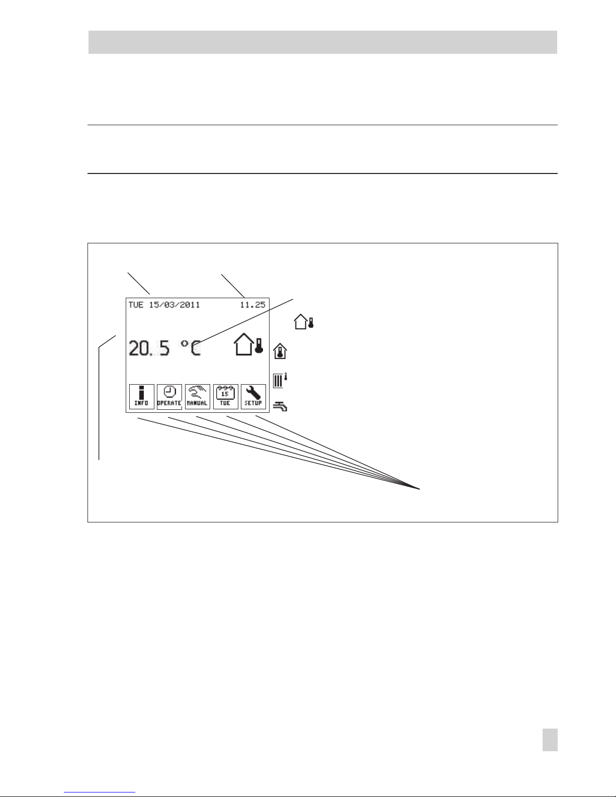
Fig. 1 · Start screen
System date System time
Temperature reading:
Outdoor temperature (for heating systems with
outdoor sensor)
Room temperature (for heating systems with room
sensor, without outdoor sensor)
Flow temperature (for heating systems without
outdoor sensor, without room sensor)
Flow temperature (for DHW circuits)
Additional information, e.g. 'Special
time-of-use active' or 'Manual mode
active'
Operator keys (page 9)
*
Page 10

Operator keys
Press this key to go to the Information menu.
This key only appears when no errors exist.
Press this key to go to the Information menu and the Error menu item.
This key blinks when the controller has detected an error.
Press this key to go to the Operation menu.
This key only appears when manual mode is inactive.
Press this key to exit the manual mode.
This key only appears when manual mode is active.
Press this key to go to the Manual menu.
Press this key to go to the Times-of-use menu.
The current day of the week (MON, TUE, WED, THU, FRI, SAT, SUN) is displayed.
Press this key to go to the Setup menu.
Note: The displays shown in these instructions represent the displays seen when system
Anl. 2.1.0 has been selected. This system consists of heating circuit 1 (HC1) and DHW heating
(DHW).
Menu items relating to control circuits are only displayed when the configured system has the
corresponding control circuit.
10 EB 5610 EN
Operation
Page 11
2.1 Information menu
The Information menu contains current details on the control process and the controller. If the
controller detects an error, an error list is displayed on the first screen of the Information menu.
Refer to section 9.
EB 5610 EN 11
Operation
Page 12
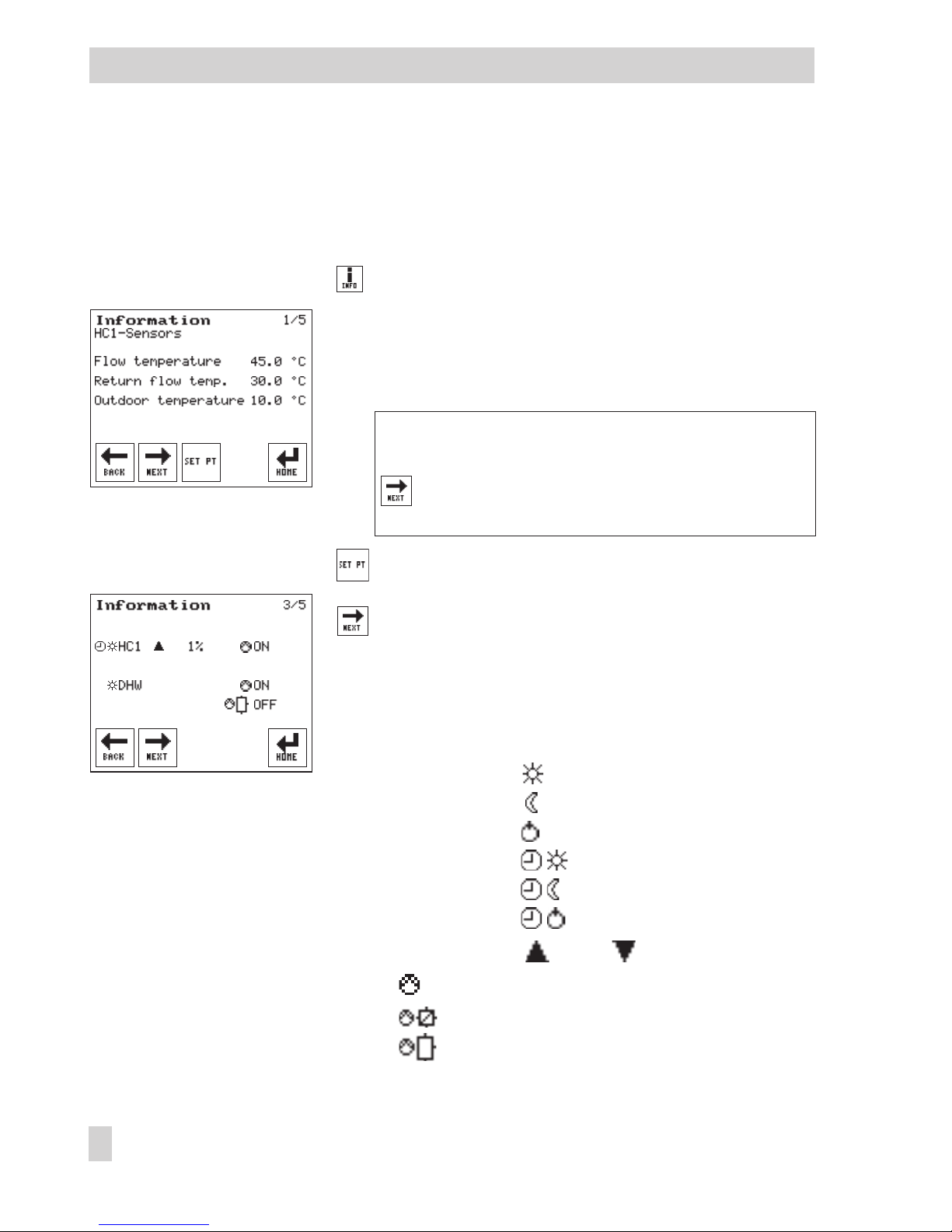
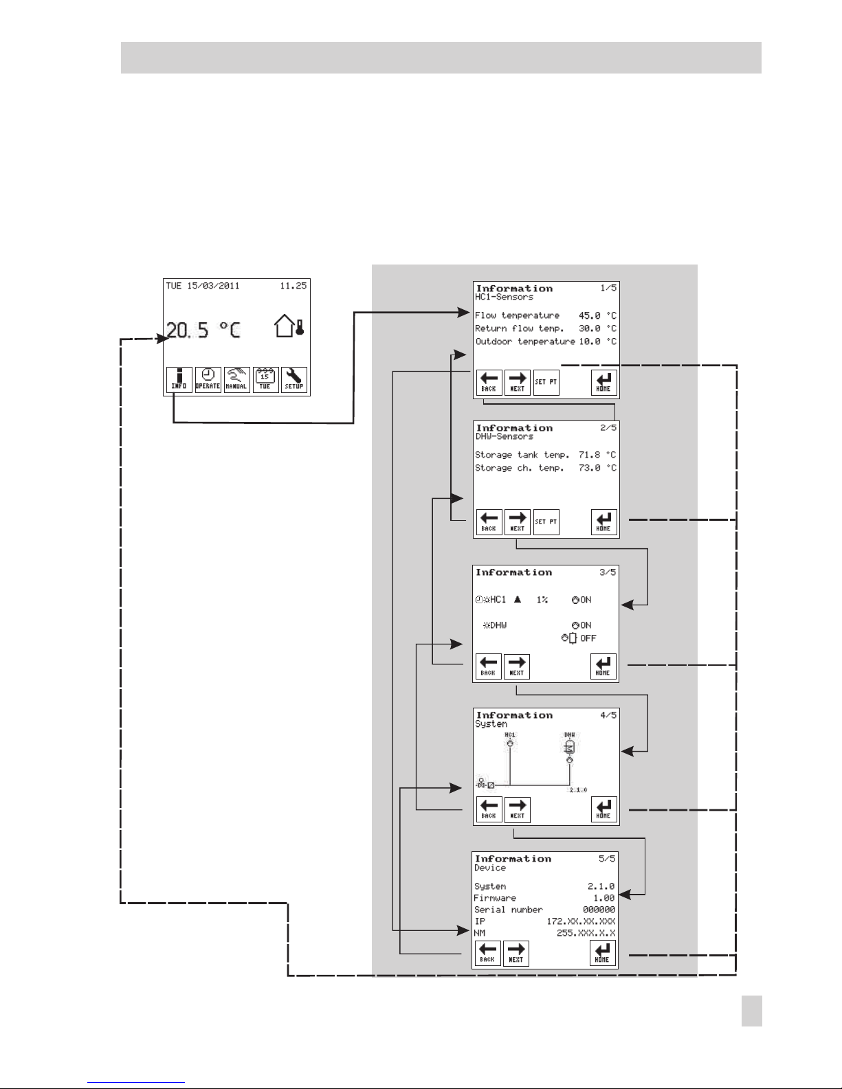
2.1.1 Retrieving information
The following instructions describe the procedure starting from the start screen (see page 9). No
errors exist in the example below.
Open the Information menu.
Sensor data
The screen displays information on the HC1 sensors. The
measured temperatures of the control circuit (specified
in the second row) are shown on the screen.
Standard version and heating systems with two control
circuits:
Select screen displaying information on the DHW
sensors for DHW heating, if required.
Read set points.
Select screen displaying an overview.
Overview of control circuit
Operating modes, valve position and pump states are
displayed depending on the control circuit.
The symbols have the following meaning:
Operating mode: Day
Night
Stand-by
Automatic and day
Automatic and night
Automatic and stand-by
Valve position: opens, closes
Heating pump, circulation pump (DHW)
Heat exchanger charging pump
Storage tank charging pump
12 EB 5610 EN
Operation
Page 13
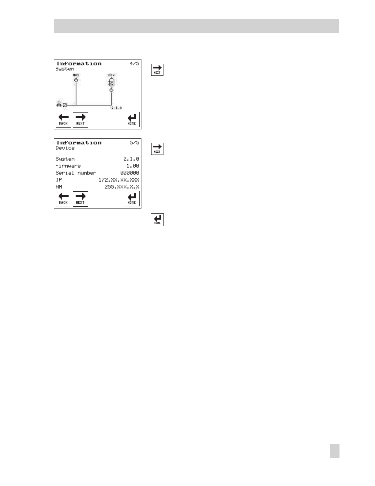
Select screen displaying information on the system.
Information on the system
This screen shows the schematics of the currently se
-
lected system.
Select screen displaying information on the device
(controller).
Information on the device (controller)
The currently selected system code number, the control
-
ler firmware and the serial number are listed.
Return to start screen.
EB 5610 EN 13
Operation
Page 14
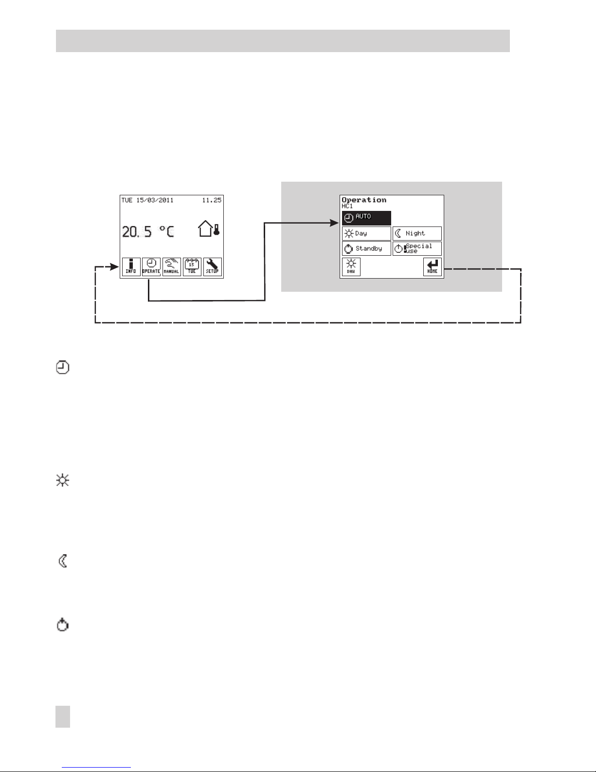
2.2 Operation menu
The operating mode is selected in the Operation menu.
The Operation menu cannot be selected when the controller is in manual mode. In this case, you
must first exit the manual mode (→Section 4).
The following operating modes are available.
Auto: The controller uses the day set points within the times-of-use and the night set points
outside the times-of-use (→Section 3.1).
If the times-of-use have not been changed, the controller uses the day set points between
06:00 and 22:00 h for control (→Section 2.3).
The heating circuit is deactivated accordingly when the heating circuit has an outdoor
sensor and the outdoor temperature exceeds the HC day or night deactivation value
(→Section 3.1).
Day: Regardless of the programmed times-of-use and summer mode, the days set points
are used by the controller (→Section 3.1).
The heating circuit continues to run when the heating circuit has an outdoor sensor and
the outdoor temperature exceeds the HC day deactivation value (→Sections 3.1 and
6.4.1).
Night: Regardless of the programmed times-of-use, the night set points are used by the
controller (Setting the set points→Section 3.1).
The heating circuit is deactivated when the heating circuit has an outdoor sensor and the
outdoor temperature exceeds the HC night deactivation value (→Sections 3.1 and 6.4.2).
Stand-by: Regardless of the programmed times-of-use, the control process is deactivated.
Only the frost protection is activated, if required.
14 EB 5610 EN
Operation
Page 15
When outdoor temperatures below the adjustable 'Outdoor temperature for frost protec
tion' are registered, the frost protection symbol appears on the screen instead of
(→Section 8.2).
Special times-of-use: The controller switches to the day, night or stand-by mode regard
less of the adjusted operating mode. In this way, the following special uses can be de
fined:
4
Party mode: The day mode continues to run (day set points are used) even after the
time-of-use has finished.
4
Public holiday mode: The day mode is extended (day set points are used) to a con
-
tinuous time-of-use, e.g. on public holidays
4
Vacation mode: Night mode or stand-by mode activated for long periods, e.g. dur
-
ing vacations
A maximum of ten time periods can be defined in which the controller switches to day,
night or stand-by mode regardless of the programmed operating mode.
After a defined special time-of-use has elapsed, it is automatically deleted.
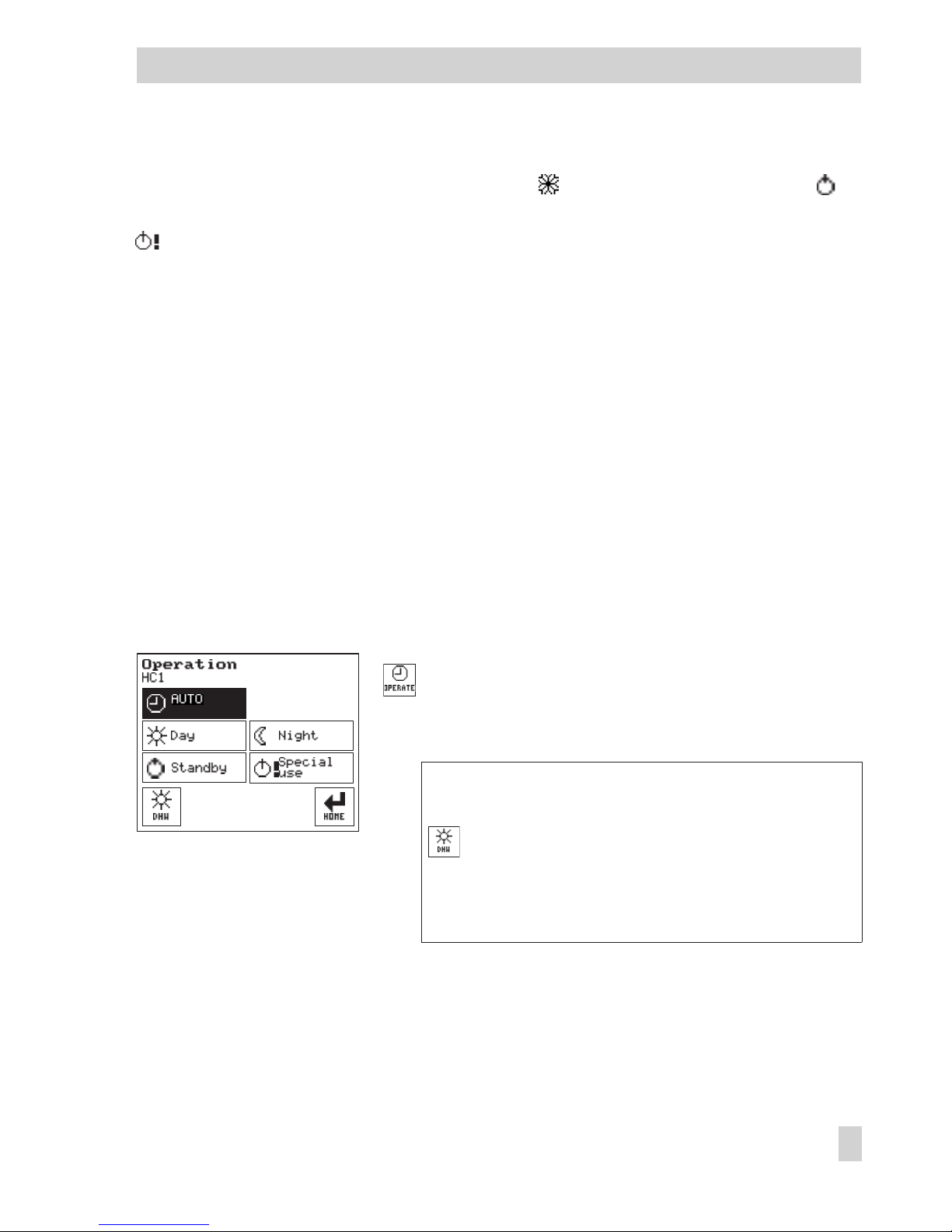
2.2.1 Selecting the operating mode
The following instructions describe the procedure starting from the start screen (see page 9). The
controller is running in normal control operation in this example.
Open the Operation menu.
The current operating mode of the control circuit (speci
-
fied in the second row) is activated (dark background).
Standard version and heating systems with two control
circuits:
Open Operation menu for DHW heating, if re
-
quired.
Note: The symbol in the key indicates which operating
mode is currently active for the control circuit.
EB 5610 EN 15
Operation
Page 16
Select the operating mode that you required.
Define special time-of-use (→Section 2.2.2) or
Return to start screen.
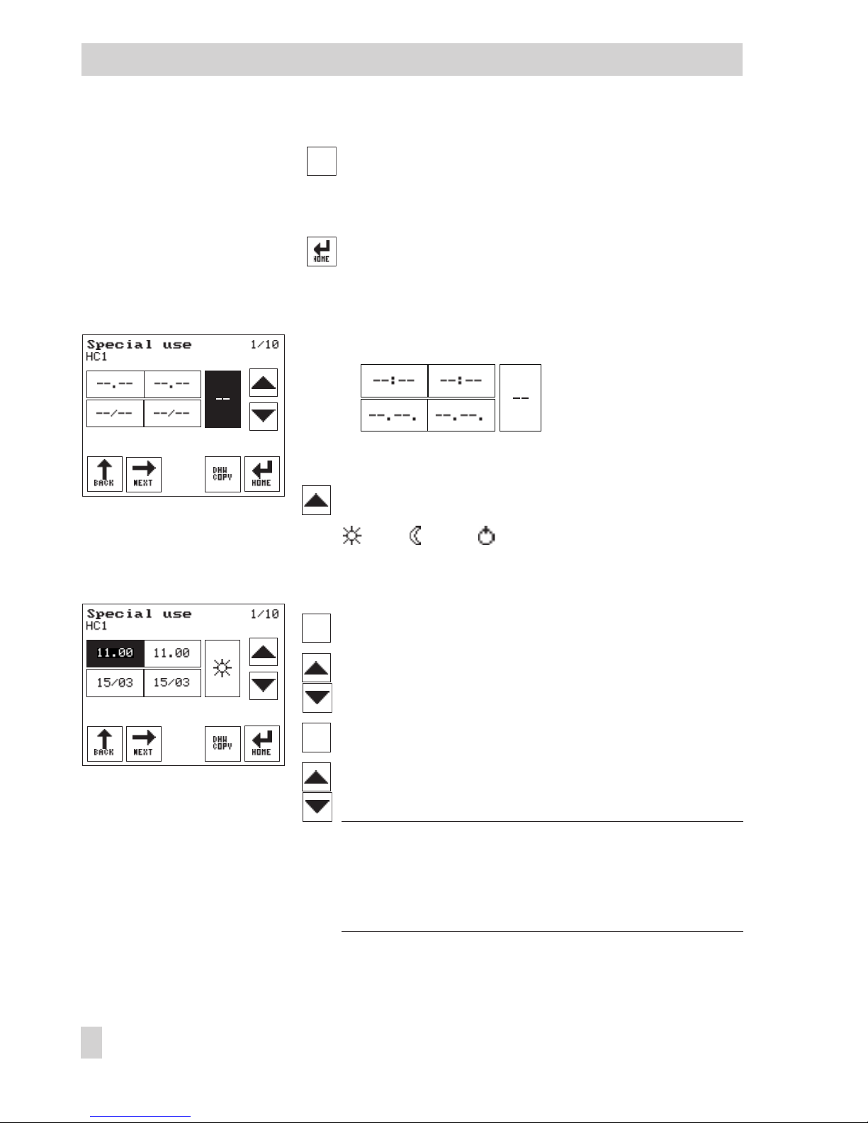
2.2.2 Defining special times-of-use
The following buttons appear:
The operating mode button (1) is activated.
Select the operating mode for the special time-of-use:
day, night, stand-by, – – time inactive
The start and stop times are set to the current time (hour),
while the start and stop dates are set to the current date.
Press the start time button (2).
Set the start time (in steps of 15 minutes).
Press the stop time button (3).
Set the stop time (in steps of 15 minutes).
Note: If the start time or date is selected to be after the stop
time or date, 'Invalid entry' blinks on the screen. This mes
-
sage is deleted as soon as the start time or date is cor
-
rected and set before the stop time or date.
16 EB 5610 EN
Operation
1
2 3
54
1 Operating mode
2 Start time 3 Stop time
4 Start date 5 Stop date
Page 17
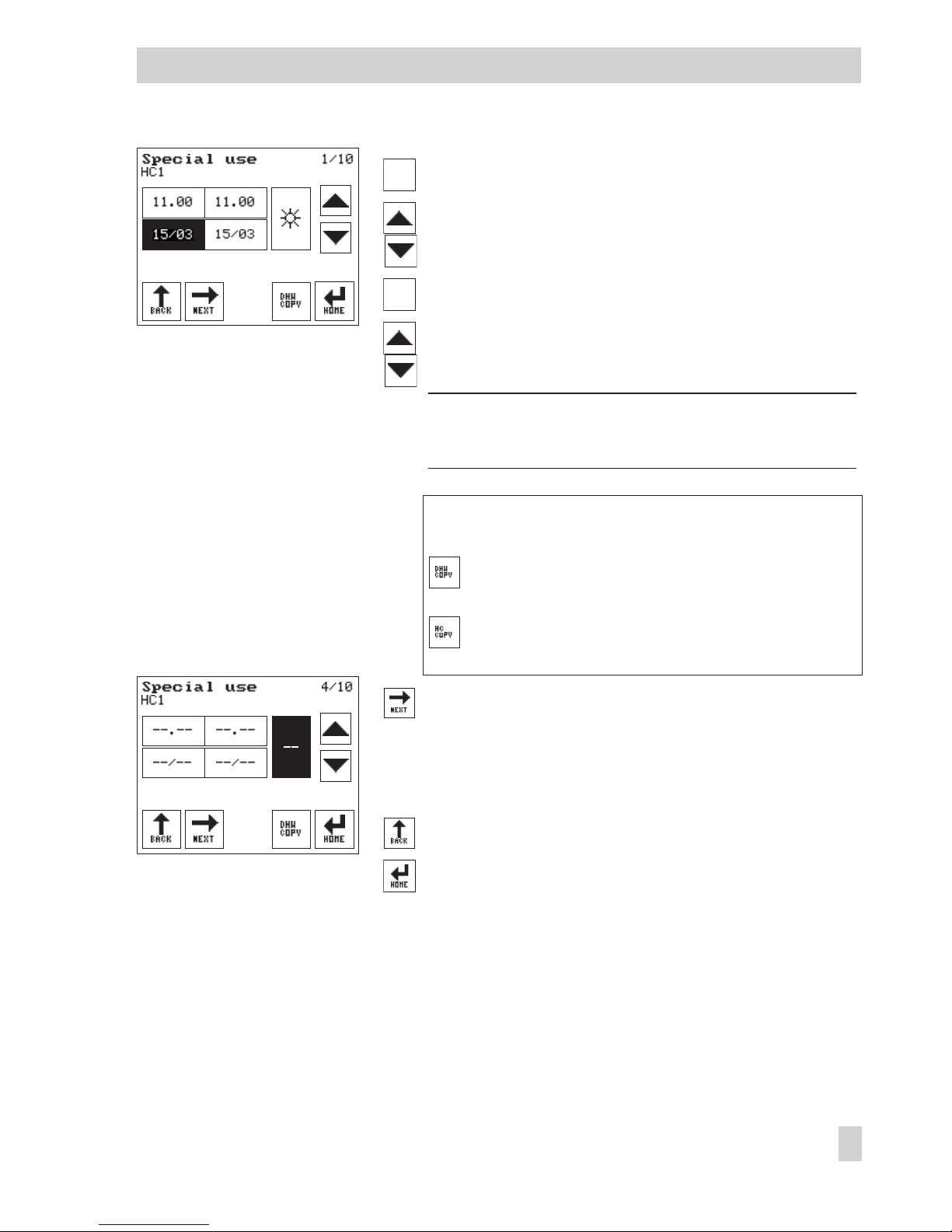
Press the start date button (4).
Set the start date.
Press the stop date button (5).
Set the stop date.
Note: If the special time-of-use is only to be valid for one
day, set the start and stop dates to the same date.
Standard version and heating systems with two control
circuits:
If required, copy the special times-of-use settings
for the heating circuit to the DHW circuit.
If required, copy the special times-of-use settings
for the DHW circuit to the heating circuit.
Select further special time-of-use (2/10, …, 10/10).
Set other special times-of-use in the same manner as de
-
scribed above.
Return to Operation menu or
Return to start screen.
EB 5610 EN 17
Operation
Page 18
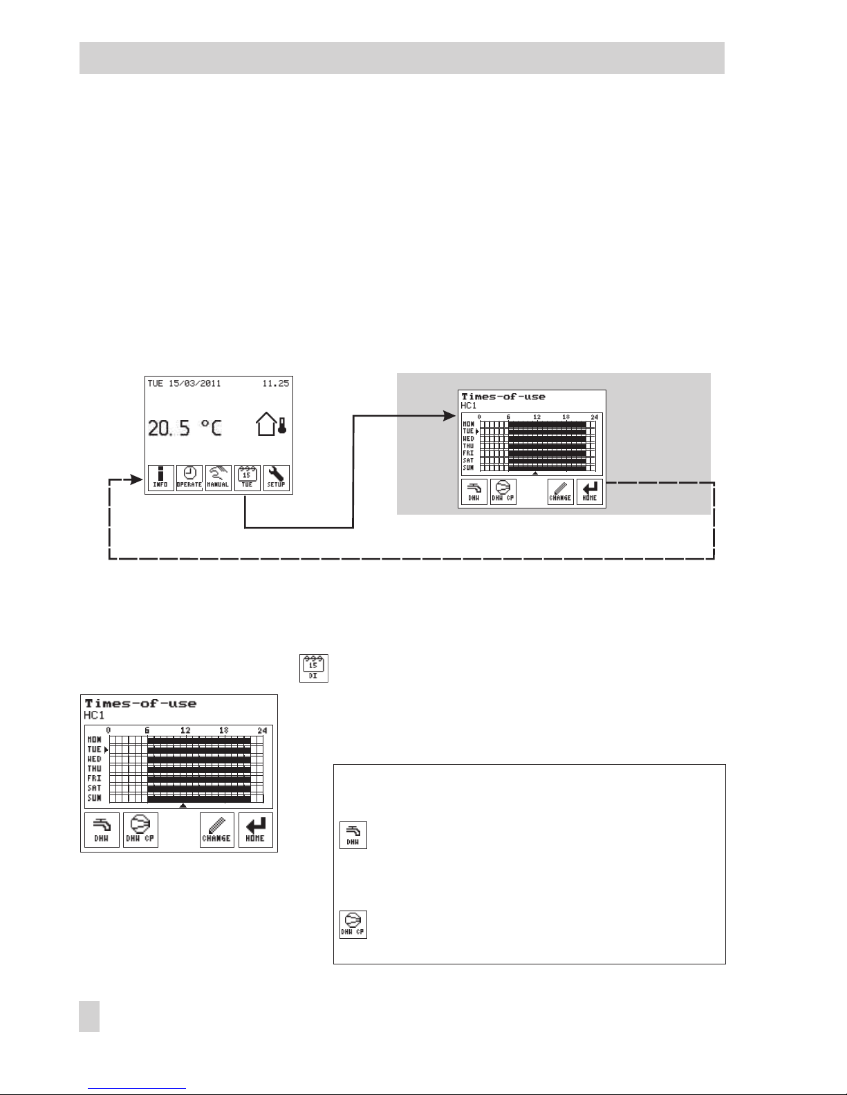
2.3 Times-of-use menu
Three times-of-use can be programmed for each day of the week in the Times-of-use menu. The
time can be set between 00:00 and 24:00 h. The times-of-use are programmed separately for
each control circuit. The controller is delivered with the following default times-of-use:
4
Times-of-use for heating circuit HC1: 06:00 to 22:00 h
4
Times-of-use for DHW heating: 00:00 to 24:00 h
4
Times-of-use for circulation pump (DHW CP): 00:00 to 24:00 h
In automatic mode, the day set points are used during the times-of-use and the night set points
outside the times-of-use.
2.3.1 Changing the times-of-use
The following instructions describe the procedure starting from the start screen (see page 9).
Open Times-of-use menu.
The times-of-use for the control circuit (specified in the
second row) are indicated by black bars for each day of
the week. The arrows indicate the current day and time.
Standard version and heating systems with two control
circuits:
If required, open the Operation menu for DHW
heating.
Systems with DHW heating:
If required, open the Operation menu for the circu
-
lation pump (DHW CP).
18 EB 5610 EN
Setup settings
Page 19
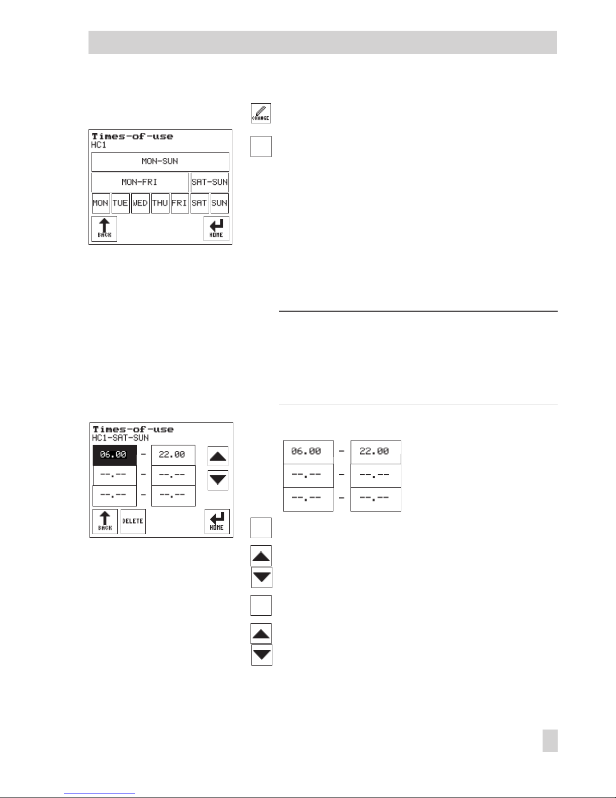
Press to change the times-of-use.
Select period to be changed:
–
[MON–SUN] to change the times-of-use to be identi
-
cal for the entire week
–
[MON–FRI] to change the times-of-use to be identical
for all weekdays
–
[SAT–SUN] to change the times-of-use to be identical
at the weekend
–
[MON], [TUE], [WED], [THU], [FRI], [SAT], [SUN] to
change the times-of-use individually for each day of
the week
Note: The settings for individual days [MON], [TUE] etc.
have priority over the settings for multiple days. The settings for weekdays [MON–FRI] and weekend
[SAT-SUN] have priority over the setting for the entire
week [MON-SUN].
The following buttons appear:
Press the start time button (1, 3 or 5).
Set the start time.
Press the stop time button (2, 4 or 6).
Set the stop time.
EB 5610 EN 19
Manual mode
1
2
3
4
5
6
1 Start time 2 Stop time 1st time
3 Start time 4 Stop time 2nd time
5 Start time 6 Stop time 3rd time
Page 20

Deleting times-of-use
Press the start or stop time button of the time-of-use
you want to delete.
Delete the time-of-use.
Return to Time-of-use menu or
Return to start screen.
Manual mode
EB 5610 EN 20
Page 21
3 Setup settings
In the Setup menu, you can change settings that were made with the Start-up wizard:
4
Change the language (refer to section 3.6)
4
Change the system time (refer to section 3.3)
4
Change the system code number (refer to section 3.7.1)
In addition, the controller can be adapted to your requirements:
4
Change set points and deactivation values (refer to section 3.1)
4
Activate or deactivate functions (refer to section 3.7.2)
4
Set parameters (refer to section 3.8)
Furthermore, the controller can be adapted to the location where it is installed by changing the
display settings. The display can be recalibrated:
4
Alter contrast and brightness (refer to section 3.2)
4
Calibrate the display (refer to section 3.4)
EB 5610 EN 21
Setup settings
D
A'
A
C
B
Page 22
22 EB 5610 EN
Setup settings
B
C
D
A'
A
Page 23
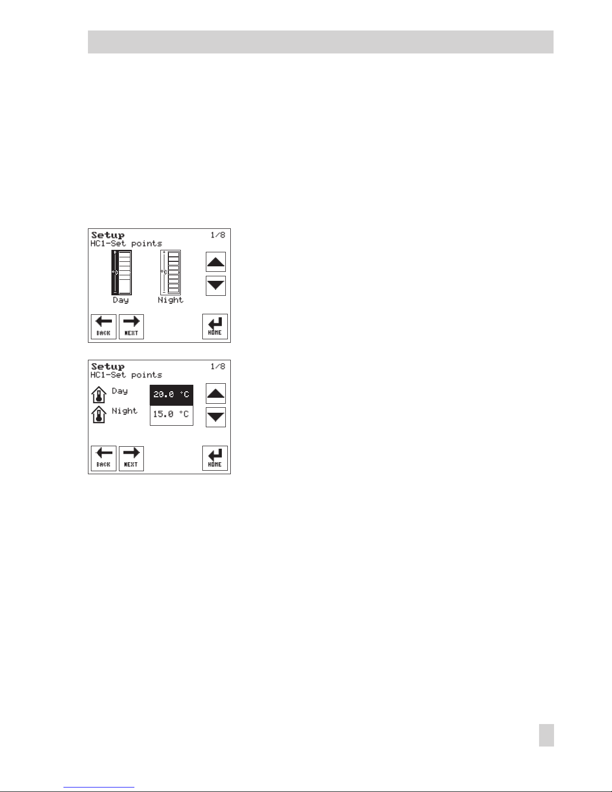
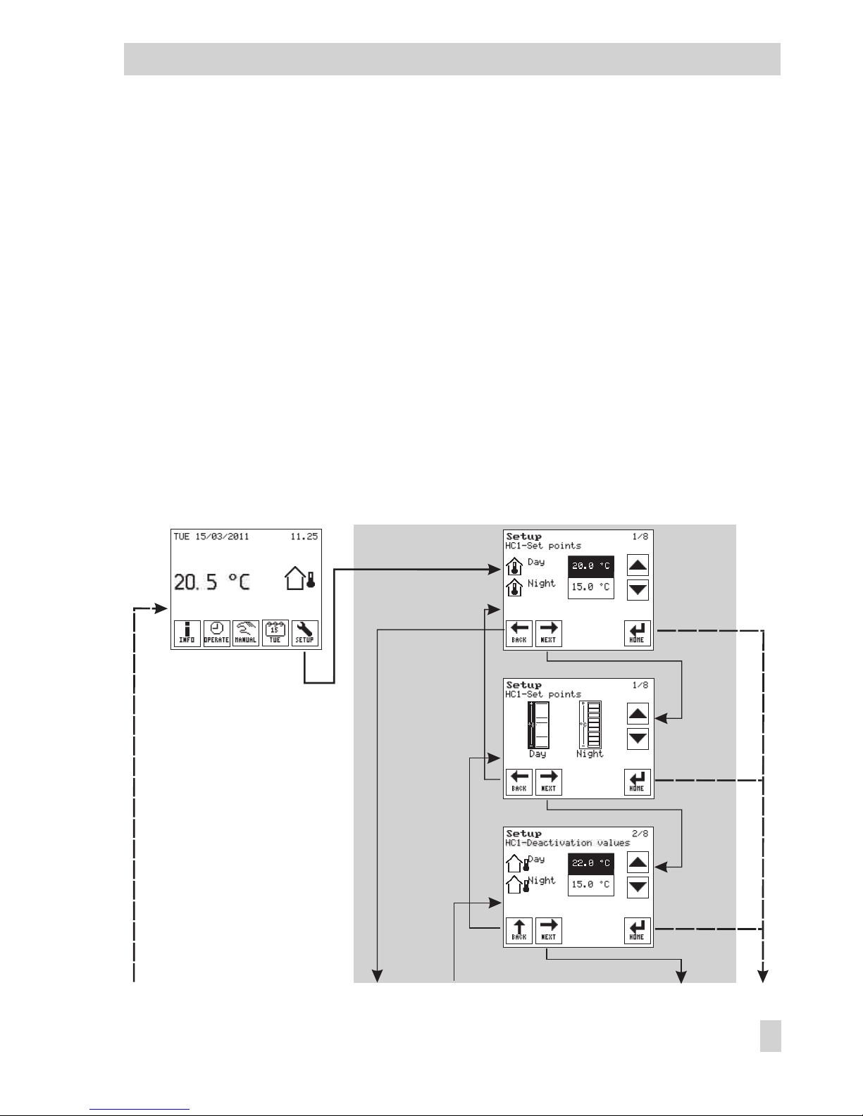
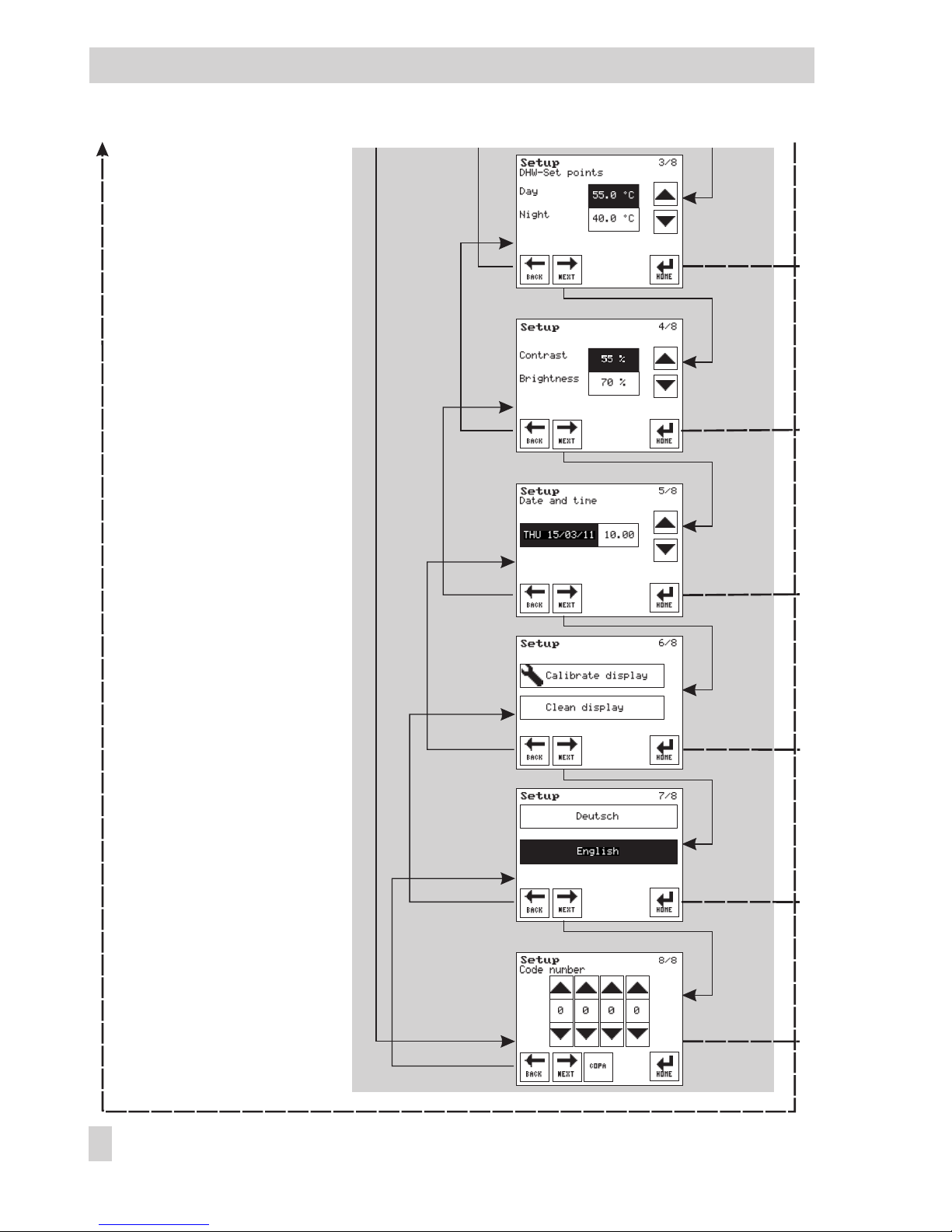
3.1 Changing set points and deactivation values
You can adapt the control process to your individual requirements by simply changing set
points and deactivation values.
HC1 set points
The HC1 set points can be defined to raise or reduce the room temperature during the
times-of-use (day) or outside the times-of-use (night).
In systems without room sensor, the exact room temperature is
not known. The set points are raised or reduced by 2 K in four
stages.
In systems with room sensor, the room temperature of the reference room in which the room sensor is located is defined by
changing an absolute value.
DHW set points
The DHW temperature during the times-of-use (day) and outside the times-of-use (night) can be
defined by changing DHW set points. The set points are defined by changing an absolute value.
HC1 deactivation values
The HC1 deactivation values can be defined for heating circuit HC1 when the heating circuit has
an outdoor sensor AS.
The HC deactivation values can be used to switch the heating circuit HC1 dependent on the out
-
door temperature during the times-of-use (day) and outside the times-of-use (night):The heating
circuit is deactivated when the outdoor temperature exceeds the deactivation value. The heating
circuit is reactivated when the outdoor temperature falls below the deactivation value again.
EB 5610 EN 23
Setup settings
Page 24
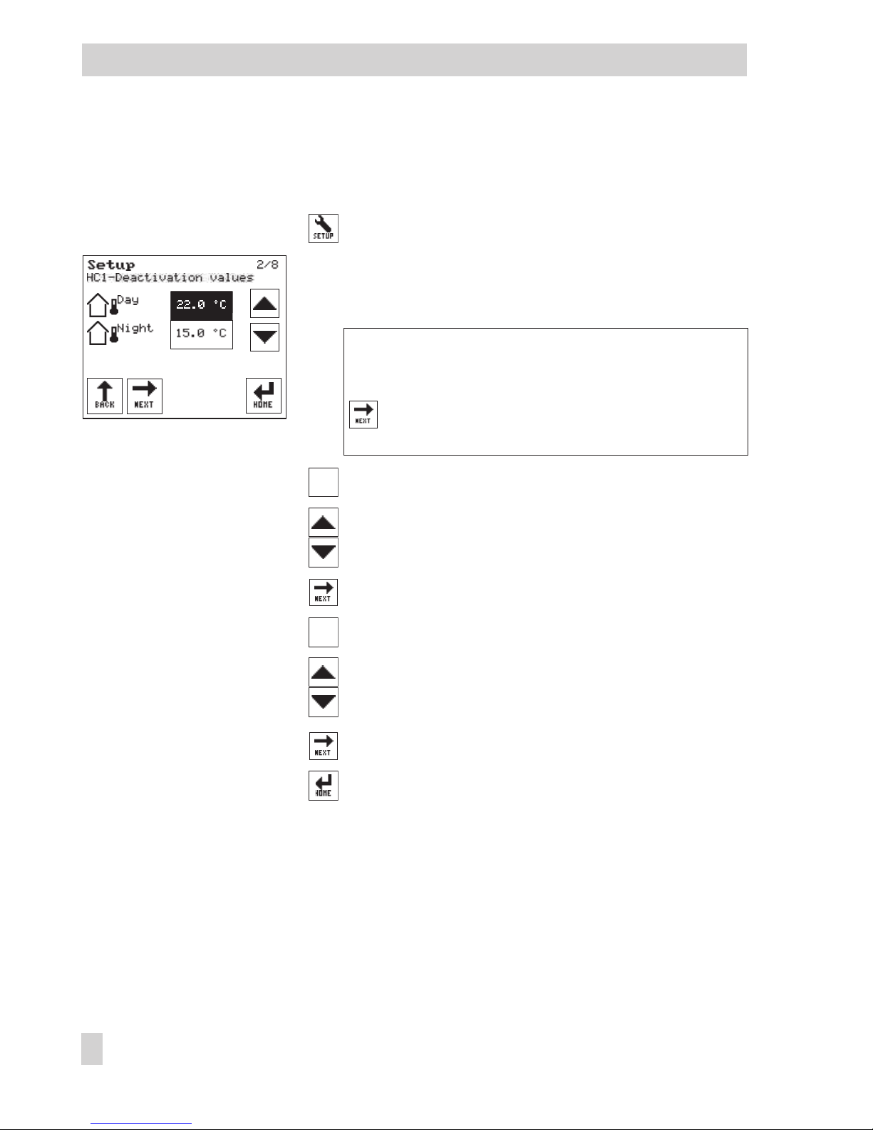
Changing set points and deactivation values
The following instructions describe the procedure starting from the start screen (see page 9).
Open the Setup menu.
The set points for the control circuit (specified in the sec
-
ond row) are shown. The current day set point is acti
-
vated (dark background).
Standard version and heating systems with two control
circuits:
If required, select the set points for DHW heat
-
ing.
If required, select the button for night set point.
Change the set point.
If required, select the button for deactivation values.
If required, select the button for night deactivation
value.
Change the deactivation value.
Perform further changes in the Setup menu or
Return to start screen.
24 EB 5610 EN
Setup settings
Page 25
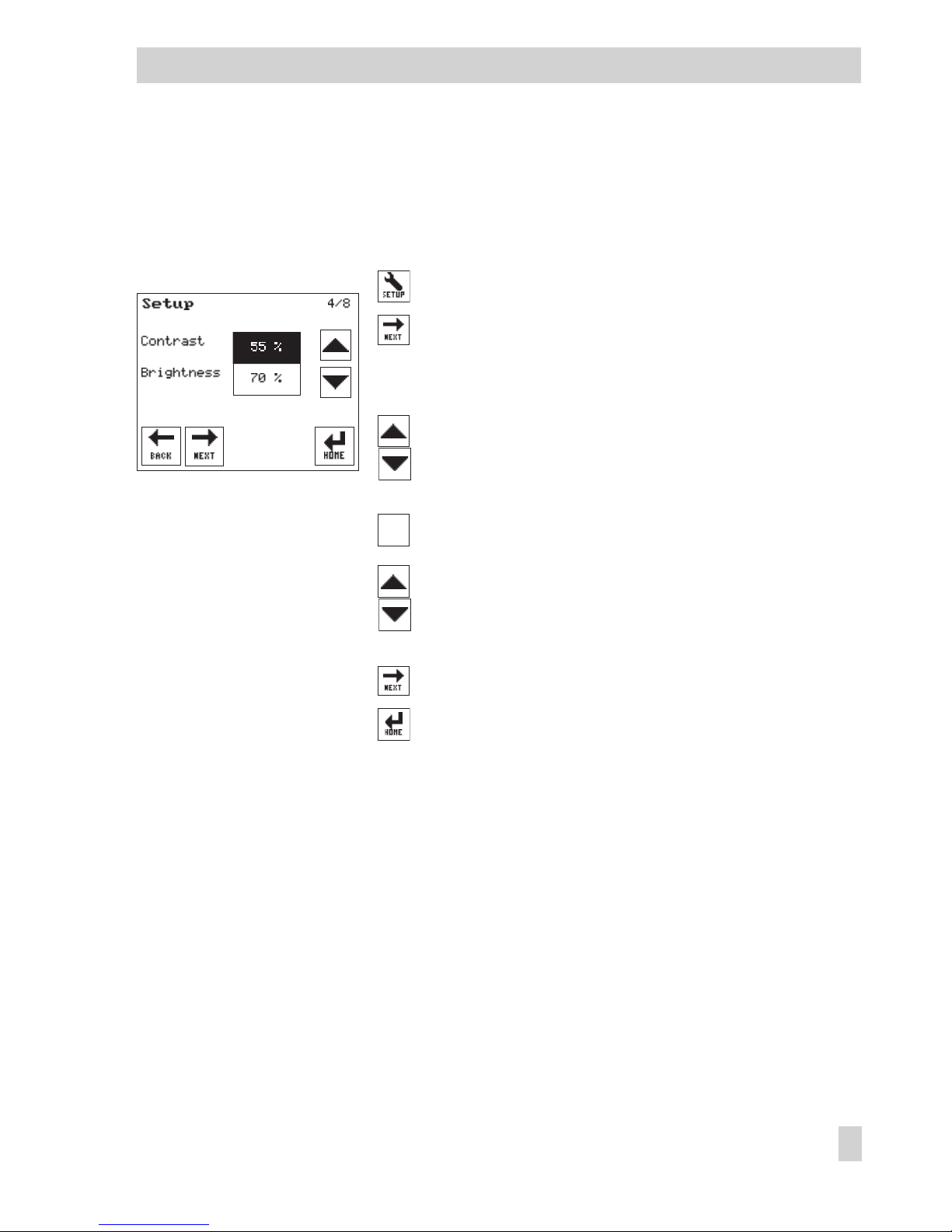
3.2 Altering the screen contrast or brightness
You can alter the contrast and brightness of the screen.
The following instructions describe the procedure starting from the start screen (see page 9).
Open the Setup menu.
Select menu item for contrast and brightness.
The current contrast setting is activated (dark
background).
Adjust contrast.
Press button for brightness setting.
Adjust brightness.
Perform further changes in the Setup menu or
Return to start screen.
EB 5610 EN 25
Setup settings
Page 26
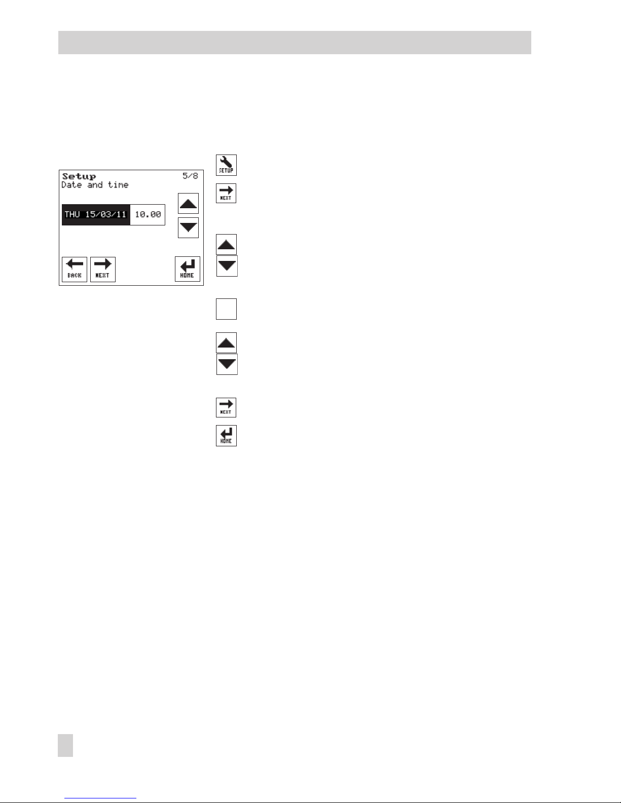
3.3 Changing the system date and time
The following instructions describe the procedure starting from the start screen (see page 9).
Open the Setup menu.
Select menu item for date and time.
The date setting button is activated (dark background).
Change the date.
Press button for the time setting.
Change the time.
Perform further changes in the Setup menu or
Return to start screen.
26 EB 5610 EN
Setup settings
Page 27
EB 5610 EN 27
Setup settings
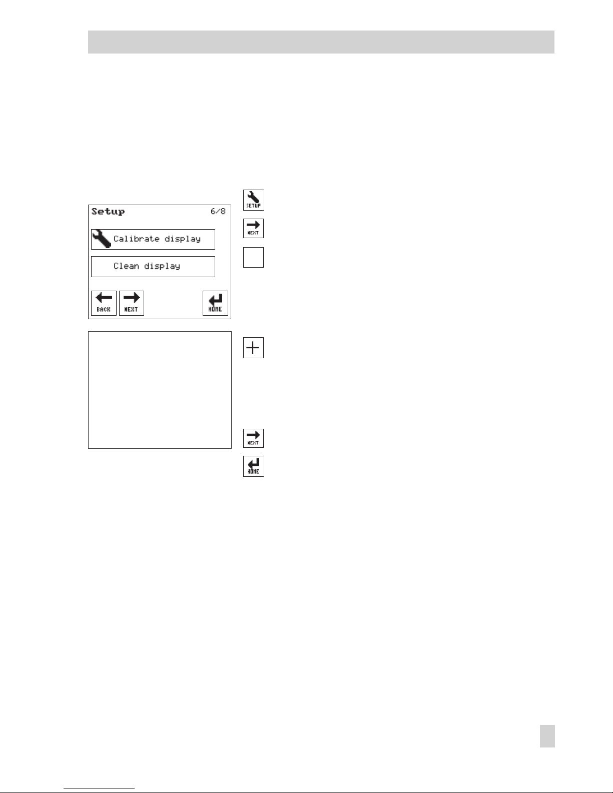
3.4 Calibrating the display
Calibration improves the precision of the touch screen. If you notice that the touch screen does
not respond correctly when you press keys on the screen, perform a calibration.
The following instructions describe the procedure starting from the start screen (see page 9).
Open the Setup menu.
Select menu item for calibrate/clean display.
Press 'Calibrate display' button.
A cross (+) appears at different places on the touch screen
in sequence.
Touch the cross repeatedly.
The calibrating process is completed when the 'Calibrate
display' and 'Clean display' buttons reappear.
Perform further changes in the Setup menu or
Return to start screen.
+
Page 28
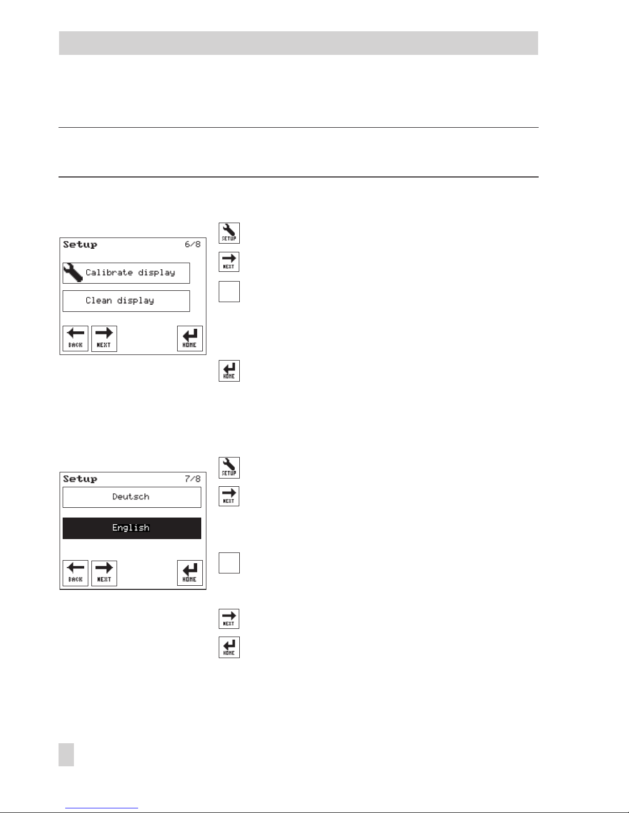
3.5 Cleaning the display
NOTICE
Do not use solvents to clean the touch screen!
The following instructions describe the procedure starting from the start screen (see page 9).
Open the Setup menu.
Select menu item for calibrate/clean display.
Press 'Clean display' button.
The touch screen is deactivated for 30 seconds. During the
countdown, the display can be cleaned with a damp
microfiber cloth.
Return to start screen.
3.6 Changing the language setting
The following instructions describe the procedure starting from the start screen (see page 9).
Open the Setup menu.
Select menu item for language.
The current language setting is activated (dark back
-
ground).
Press the language required.
Perform further changes in the Setup menu or
Return to start screen.
28 EB 5610 EN
Setup settings
Page 29
3.7 Configuring the controller and changing parameter settings
To adapt the controller to your control requirements, you can activate or deactivate functions as
required. Depending on the activated functions, function block parameters and single parame
-
ters can also be adapted to individual requirements. Functions and parameters are described in
sections 6, 7 and 8.
The functions and parameters are assigned to the individual configuration and parameter levels
depending on the controller action required (overview of all functions and parameter levels
→
Sections 13.1 and 13.2):
4
Screen displaying the system schematics
4
Configuration level (CO level):
– HC1–CO1 (only for systems with HC1)
– DHW–CO4 (only for systems with DHW)
– HC1–CO5
4
Parameter levels (PA levels):
– HC1–PA1 (only for systems with HC1)
– DWW–PA4 (only for systems with DHW)
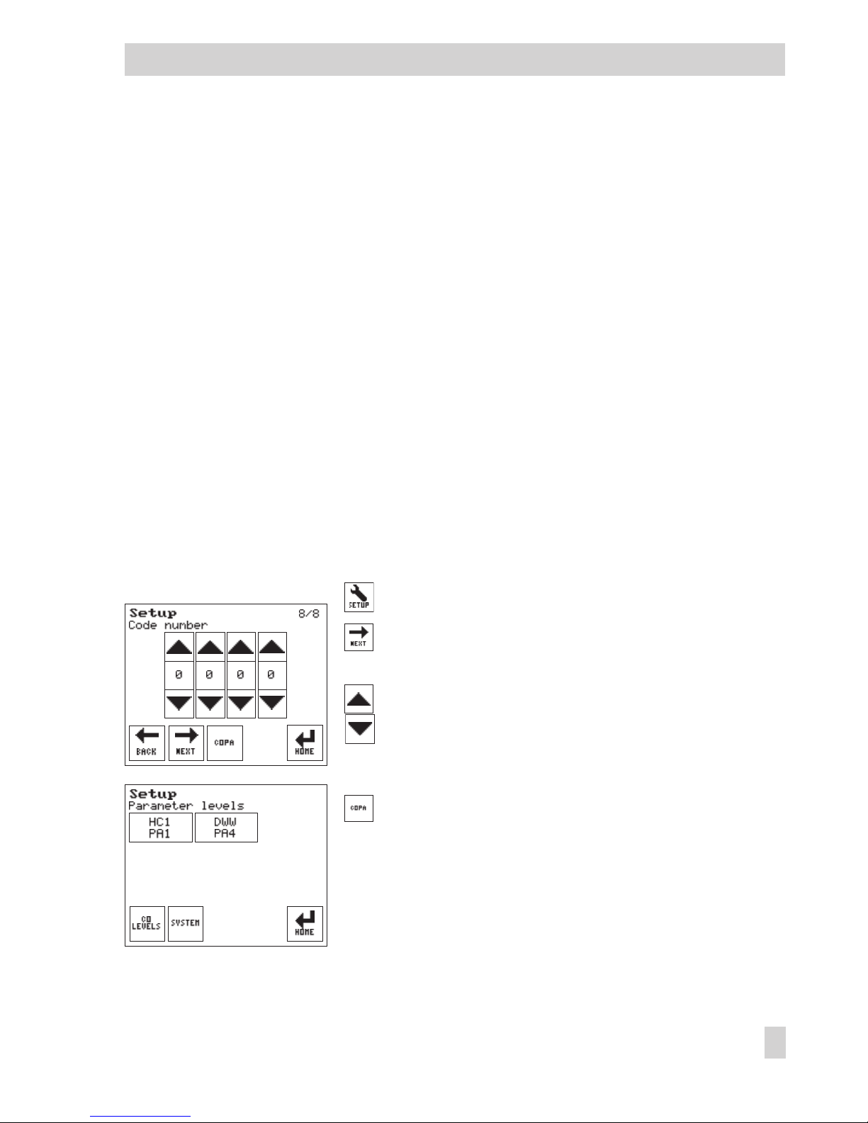
The system configuration and parameter settings can only be changed after you enter a valid
key number. The valid key number is stated on page 126.
Open the Setup menu.
Select the menu item for the key number.
The key number 0000 appears.
Enter the valid key number.
Open the configuration and parameter level.
The various parameter levels belonging to the currently
selected system are shown.
EB 5610 EN 29
Setup settings
Page 30
30 EB 5610 EN
Setup settings
3.7.1 Changing the system code number
Any setup settings that have been made are reset when the system code number is changed.
NOTICE
The wiring differs depending on the system. Before changing the system code number, the elec
-
trical connections may need to be changed. Refer to sections 5 and 11.
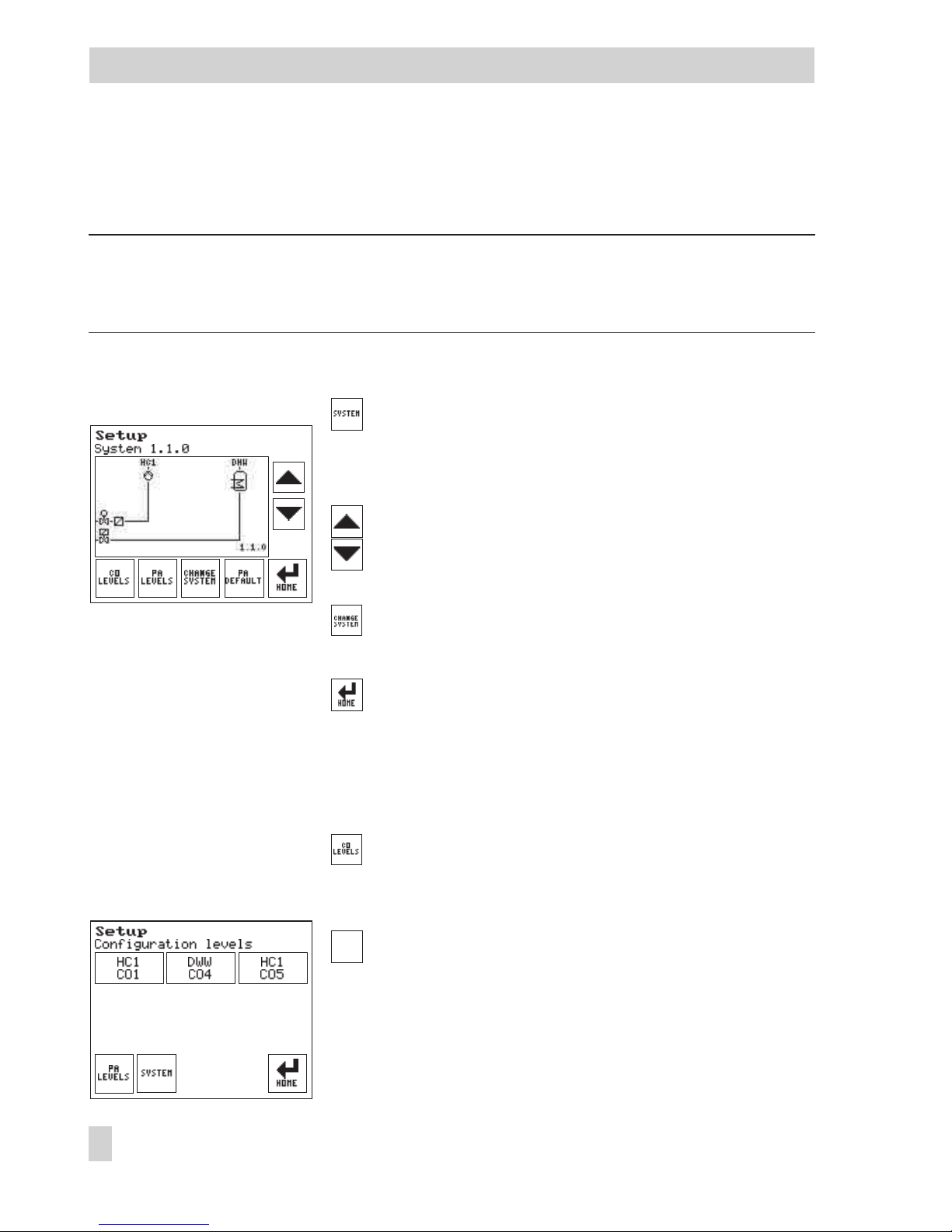
The following instructions start from the configuration and parameter level (see page 29).
Open the screen displaying the system schematics.
The schematics of the currently valid system are shown
(see section 5).
Select a different system.
Confirm the new system.
'System saved' appears on the screen.
Return to start screen.
3.7.2 Activating or deactivating functions
The following instructions start from the configuration and parameter level (see page 29).
Select the menu item for configuration levels.
The various configuration levels of the currently valid
system appear.
Select the configuration level. Depending on the cur
-
rently valid system:
4
HC1–CO1
4
DHW–CO4
4
HC1–CO5
Page 31

The function blocks of the activated configuration levels
are shown together with their current setting
(0 = OFF, 1 = ON).
Go directly to the function block or
Select function blocks one after the other.
Activate or deactivate the function block.
Function blocks with function block parameters:
Press function block parameter button.
Select a function block parameter.
Set the function block parameter.
Return to the configuration level.
Go to the next configuration block or
Return to the configuration and parameter level or
Return to start screen.
EB 5610 EN 31
Setup settings
Page 32

3.8 Setting parameters
The following instructions describe the procedure starting from the configurationand parameter
level (see page 29).
Open the configuration and parameter level.
The various parameter levels of the currently valid sys
-
tem appear.
Select the parameter level.
The parameters of the activated parameter level are
listed on the screen.
Go directly to the parameter or
Select parameters one after the other.
Set the parameter.
Go to the next parameter or
Return step-by-step to the configuration and parameter
level or
Return to start screen.
Note: All parameters can be reset to their default settings by pressing in the system level
(→Section 3.7.1).
32 EB 5610 EN
Setup settings
Page 33

4 Manual mode
All outputs can be set in the manual mode:
4
M (control valve): control output in percent
4
UP (heating pump): switching pump on and off (ON/OFF)
4
SLP (storage tank charging pump): switching pump on and off (ON/OFF)
4
ZP (circulation pump): switching pump on and off (ON/OFF)
NOTICE
The heating is not monitored for frost protection in manual mode.
The following instructions describe the procedure starting from the start screen (see page 9).
Open the Manual menu.
The outputs of the control circuit (specified in the sec
-
ond row) are shown.
Select the output you want to control manually.
Set output.
The output immediately switches from automatic mode
to the manual mode .
Standard version and heating systems with two control
circuits:
Select the manual mode for DHW heating, if
required.
Set the other outputs in the same manner as described
above.
EB 5610 EN 33
Manual mode
Page 34

When all outputs have been set:
Return to start screen
The hand icon under the date indicates active manual
operation.
The key is replaced by the key on the start
screen.
Exit manual mode
Exit manual mode.
The key is replaced by the key on the start
screen (see page 9).
34 EB 5610 EN
Manual mode
Page 35

5 Systems
System Anl 1.0.0
Default settings
HC1–CO1–01 OFF (without S4/S5)
HC1–CO1–02 ON (with S2)
HC1–CO1–03 ON (with S3)
See fold-out page for wiring required for functions.
EB 5610 EN 35
Systems
BE
BA
Pt 1000
3-Pkt/0...10 V*
S3
S1
M1/UO1*
S2
P1
S4/S5
* Compact version: Without UO1, 0 to10 V
Page 36

System Anl 1.0.1
Default settings
HC1–CO1–01 OFF (without S4/S5)
HC1–CO1–02 ON (with S2)
HC1–CO1–03 OFF (without S3)
See fold-out page for wiring required for functions.
36 EB 5610 EN
Systems
BE
BA
Pt 1000
3-Pkt/0...10 V*
S2
S4/S5
S3
S1
P1
M1/UO1*
* Compact version: Without UO1, 0 to10 V
Page 37

System Anl 1.1.0 (standard version only)
Default settings
HC1–CO1–01 OFF (without S4/S5)
HC1–CO1–02 ON (with S2)
HC1–CO1–03 ON (with S3)
DHW–CO4–01 ON (with S7)
See fold-out page for wiring required for functions.
EB 5610 EN 37
Systems
BE
BA
Pt 1000
3-Pkt/0...10 V
WW
KW
S2
M2+
P2
S7
S3
S1
M1/UO1
P1
S4/S5
Page 38

System Anl 1.1.1 (standard version only)
Default settings
HC1–CO1–01 OFF (without S4/S5)
HC1–CO1–02 ON (with S2)
HC1–CO1–03 OFF (without S3)
DHW–CO4–01 ON (with S7)
See fold-out page for wiring required for functions.
38 EB 5610 EN
Systems
BE
BA
Pt 1000
3-Pkt/0...10 V
WW
KW
S2
S4/S5
S3
S1
P1
M1/UO1
P3
P2
S7
Page 39

System Anl 1.2.0 (standard version only)
Default settings
HC1–CO1–01 OFF (without S4/S5)
HC1–CO1–02 ON (with S2)
HC1–CO1–03 OFF (without S3)
DHW–CO4–01 ON (with S7)
DHW–CO4–02 ON (with S8)
DHW–CO4–05 OFF (without S6)
See fold-out page for wiring required for functions.
EB 5610 EN 39
Systems
BE
BA
Pt 1000
3-Pkt/0...10 V
WW
KW
S2
S4/S5
S3
S1
P1
M1/UO1
S6
M2+
P3
P2
S8 S7
Page 40

System Anl 1.6.0 (standard version only)
Default settings
DHW–CO4–01 ON (with S7)
DHW–CO4–02 ON (with S8)
DHW–CO4–03 ON (with S3)
See fold-out page for wiring required for functions.
40 EB 5610 EN
Systems
BE
BA
Pt 1000
3-Pkt/0...10 V
WW
KW
S3
S1
M1/UO1
P3
P2
S8
S7
Page 41

System Anl 1.6.1 (standard version only)
Default settings
DHW–CO4–01 ON (with S7)
DHW–CO4–02 ON (with S8)
DHW–CO4–03 ON (with S3)
DHW–CO4–05 OFF (without S6)
See fold-out page for wiring required for functions.
EB 5610 EN 41
Systems
BE
BA
Pt 1000
3-Pkt/0...10 V
WW
KW
S3 S6S1
P1
M1/UO1
P3
P2
S8 S7
Page 42

System Anl 1.6.2 (standard version only)
Default settings
DHW–CO4–01 ON (with S7)
DHW–CO4–02 ON (with S8)
DHW–CO4–03 OFF (without S3)
DHW–CO4–05 OFF (without S6)
See fold-out page for wiring required for functions.
42 EB 5610 EN
Systems
BE
BA
Pt 1000
3-Pkt/0...10 V
WW
KW
S1
M1/UO1
S6
P1
S3
P3
P2
S8 S7
Page 43

System Anl 1.9.0
Default settings
DHW–CO4–03 ON (with S3)
DHW–CO4–04 OFF (without UI2)
See fold-out page for wiring required for functions.
EB 5610 EN 43
Systems
BE
BA
Pt 1000
3-Pkt/0...10 V
S3
S1
M1/UO1*
P1
UI2*
WW
F
KW
* Compact version: Without UO1, 0 to 10 V and UI2
Page 44

System Anl 1.9.1
Default settings
DHW–CO4–03 ON (with S3)
See fold-out page for wiring required for functions.
44 EB 5610 EN
Systems
BE
BA
Pt 1000
3-Pkt/0...10 V
WW
KW
P1
S1
M1/UO1*
S3
* Compact version: Without UO1, 0 to 10 V
Page 45

System Anl 2.0.0 (standard version only)
Default settings
HC1–CO1–01 OFF (without S4/S5)
HC1–CO1–02 ON (with S2)
HC1–CO1–03 ON (with S3)
DHW–CO4–01 ON (with S7)
DHW–CO4–02 OFF (without S8)
See fold-out page for wiring required for functions.
EB 5610 EN 45
Systems
BE
BA
Pt 1000
3-Pkt/0...10 V
WW
KW
P1
M2+
S3
S1
M1/UO1
S2
P2
S7
S4/S5
Page 46

System Anl 2.1.0 (standard version only)
Default settings
HC1–CO1–01 OFF (without S4/S5)
HC1–CO1–02 ON (with S2)
HC1–CO1–03 ON (with S3)
DHW–CO4–01 ON (with S7)
DHW–CO4–02 OFF (without S8)
See fold-out page for wiring required for functions.
46 EB 5610 EN
Systems
BE
BA
Pt 1000
3-Pkt/0...10 V
WW
KW
P1
P3
S3
S1
M1/UO1
S2
P2
S7
S4/S5
Page 47

System Anl 2.2.0 (standard version only)
Default settings
HC1–CO1–01 OFF (without S4/S5)
HC1–CO1–02 ON (with S2)
HC1–CO1–03 ON (with S3)
DHW–CO4–01 ON (with S7)
DHW–CO4–02 ON (with S8)
DHW–CO4–05 OFF (without S6)
See fold-out page for wiring required for functions.
EB 5610 EN 47
Systems
BE
BA
WW
KW
P1
S3
S1
M1/UO1
S4/S5
M2+
S6
P3
S8P2S7
S2
Page 48

System Anl 3.5.0
Default settings
HC1–CO1–03 ON (with S3)
See fold-out page for wiring required for functions.
48 EB 5610 EN
Systems
BE
BA
Pt 1000
3-Pkt/0...10 V*
S3 S1
M1/UO1*
P1
* Compact version: Without UO1, 0 to 10 V
Page 49

System Anl 11.0.0 (standard version only)
Default settings
HC1–CO1–01 OFF (without S4/S5)
HC1–CO1–02 ON (with S2)
HC1–CO1–03 ON (with S3)
DHW–CO4–01 ON (with S7)
DHW–CO4–03 ON (with S6)
See fold-out page for wiring required for functions.
EB 5610 EN 49
Systems
BE
BA
Pt 1000
3-Pkt/0...10 V
WW
KW
S2
M2/UO2
P2
S7
S3
S1
S6
M1/UO1
P1
S4/S5
Page 50

System Anl 11.2.0 (standard version only)
Default settings
HC1–CO1–01 OFF (without S4/S5)
HC1–CO1–02 ON (with S2)
HC1–CO1–03 ON (with S3)
DHW–CO4–01 ON (with S7)
DHW–CO4–02 ON (with S8)
See fold-out page for wiring required for functions.
50 EB 5610 EN
Systems
WW
BE
BA
Pt 1000
3-Pkt/0...10 V
S2M2/UO2
M1/UO1 P1
S4/S5S1
S6
P3
S8P2S7S3
Page 51

System Anl 11.9.0 (standard version only)
Default settings
HC1–CO1–01 OFF (without S4/S5)
HC1–CO1–02 ON (with S2)
HC1–CO1–03 ON (with S3)
DHW–CO4–03 ON (with S7)
DHW–CO4–04 OFF (without UI2)
See fold-out page for wiring required for functions.
EB 5610 EN 51
Systems
BE
BA
Pt 1000
3-Pkt/0...10 V
S2
M2/UO2
S3
S1
S7
S6
M1/UO1
P1
P2
UI2
S4/S5
F
WW
KW
Page 52

System Anl 11.9.1 (standard version only)
Default settings
HC1–CO1–01 OFF (without S4/S5)
HC1–CO1–02 ON (with S2)
HC1–CO1–03 ON (with S3)
DHW–CO4–03 ON (with S7)
DHW–CO4–04 OFF (without UI2)
DHW–CO4–05 OFF (without S6)
See fold-out page for wiring required for functions.
52 EB 5610 EN
Systems
BE
BA
Pt 1000
3-Pkt/0...10 V
WW
F
KW
S2
M2/UO2
S3
S1
S7
S8 S6
M1/UO1
P1
P3
P2
UI2
S4/S5
Page 53

6 Functions of the heating circuit
Which controller functions are available depends on the selected system number (Anl).
6.1 Weather-compensated control
When weather-compensated control is used, the flow temperature is controlled according to the
outdoor temperature. The heating characteristic in the controller defines the flow temperature
set point as a function of the outdoor temperature (–> Fig. 2). The outdoor temperature required
for weather-compensated control can either be measured at an outdoor sensor or received us
-
ing 0 to 10 V at UI1 input.
Functions WE Configuration
Outdoor temperature measure
-
ment
ON HC1–CO1–02 = ON
EB 5610 EN 53
Functions of the heating circuit
20
30
0.2
2.4
2.62.93.2
2.2
2.0
1.8
1.6
1.4
1.2
1.0
0.8
0.4
0.6
40
50
60
70
80
90
100
110
120
130
tVL[°C]
–20
[°C]
t
A
–16–12–8–4048121620
140
150
–24 –28 –32 –36 –40 –44
Fig. 2 · Gradient characteristics
t
VL
Flow temperature
t
A
Outdoor temperature
Page 54

Functions WE Configuration
Outdoor temperature 0–10 V at
UI1
OFF
–20.0 °C
50.0 °C
HC1–CO1–04 = ON
Lower transmission range value, outdoor tempera
ture/–30.0 to 100.0 °C
Lower transmission range value, outdoor tempera
ture/–30.0 to 100.0 °C
6.1.1 Gradient characteristic
Basically, the following rule applies: a decrease in the outdoor temperature causes the flow tem
perature to increase.
By varying the parameters
Gradient and Level, you can adapt the characteristic to your individ
ual requirements:
The gradient needs to be increased if the room temperature
drops when it is cold outside.
The gradient needs to be decreased if the room temperature
rises when it is cold outside.
The level needs to be increased and the gradient decreased if
the room temperature drops when it is mild outside.
54 EB 5610 EN
Functions of the heating circuit
t
VL
t
A
[˚C]
[˚C]
20 0 –20
t
VL
t
A
[˚C]
[˚C]
20 0 –20
t
VL
t
A
[˚C]
[˚C]
20 0 –20
Page 55

The level needs to be decreased and the gradient increased if
the room temperature rises when it is mild outside.
Outside the times-of-use, reduced set points are used for control:
The reduced flow set point is calculated as the difference between the adjusted values for 'HC1
day set point' (rated room temperature) and 'HC1 night set point' (reduced room temperature).
For heating systems without room sensor, the reduced flow temperature set point is based on the
'Night set-back, flow' parameter.
The 'Max. flow temperature' and 'Min. flow temperature' parameters mark the upper and lower
limits of the flow temperature. A separate gradient characteristic can be selected for the limita
-
tion of the return flow temperature.
Examples for adjusting the characteristic:
4
Old building, radiator design 90/70: Gradient approx. 1.8
4
New building, radiator design 70/55: Gradient approx. 1.4
4
New building, radiator design 55/45: Gradient approx. 1.0
4
Underfloor heating depending on arrangement: Gradient smaller than 0.5
Note: For heating systems with room sensor and without configured influence of the room tem
perature on the control process, the room temperature settings for day (HC1 day set point) and
for night (HC1 night set point) only become effective satisfactorily when the heating characteris
tic has been adapted to the building/heating surface layout.
Functions WE Configuration
Four-point characteristic OFF HC1–CO1–11 = OFF
Parameters WE Parameter settings
Flow gradient 1.4 HC1–PA1–01 / 0.2 to 3.2
Flow level 0.0 °C HC1–PA1–02 / –30.0 to 30.0 °C
Min. flow temperature 20.0 °C HC1–PA1–06 / 5.0 to 150.0 °C
Max. flow temperature 90.0 °C HC1–PA1–07 / 5.0 to 150.0 °C
Night set-back, flow 10.0 K HC1–PA1–08 / 0.0 to 50.0 K
EB 5610 EN 55
Functions of the heating circuit
t
VL
t
A
[˚C]
[˚C]
20 0 –20
Page 56

Parameters WE Parameter settings
HC1 day set point
Refer to section 3.1
HC1 night set point
56 EB 5610 EN
Functions of the heating circuit
Page 57

6.1.2 Four-point characteristic
The four-point characteristic allows you to define your own heating characteristic.
It is defined by four points for 'Outdoor temperature', 'Flow temperature', 'Reduced flow temper
ature' and 'Return flow temperature'. The 'Max. flow temperature' and 'Min. flow temperature' pa
rameters mark the upper and lower limits of the flow temperature.
Note:
–
The HC1 flow temperature set points can be raised or reduced by 2 K in four stages even
when the four-point characteristic is selected. The room temperature set points for day
and night must be set (→Section 3.1) if the supplementary functions, such as Optimiza
-
tion or Flash adaptation (the room temperature must be measured for both these func
-
tions), are configured.
–
The four-point characteristic function can only be activated when the Adaptation function
is not active.
Functions WE Configuration
Adaptation OFF HC1–CO1–10 = OFF
Four-point characteristic OFF HC1–CO1–11 = ON
EB 5610 EN 57
Functions of the heating circuit
t
VLmax
t
VLmin
t
VL
100
90
80
70
60
50
40
30
20
10
[˚C]20 15 10 5 0 –5 –10 –15 –20
P1
P2
P3
P4
[˚C]
t
A
Fig. 3 · Four-point characteristic
P1 to P4 Points 1 to 4
t
VL
Flow temperature
t
A
Outdoor temperature
… min Min. t
VL
...max Max. t
VL
Four-point characteristic
Reduced four-point characteristic
Page 58

Parameters WE Parameter settings
Outdoor Point 1
temperature Point 2
Point 3
Point 4
–15.0 °C
–5.0 °C
5.0 °C
15.0 °C
HC1–PA1–05 / –45.0 to 50.0 °C
Flow temperature Point 1
Point 2
Point 3
Point 4
70.0 °C
55.0 °C
40.0 °C
25.0 °C
HC1–PA1–05 / 5.0 to 150.0 °C
Reduced Point 1
flow temperature Point 2
Point 3
Point 4
60.0 °C
40.0 °C
20.0 °C
20.0 °C
HC1–PA1–05 / 5.0 to 150.0 °C
Return flow Point 1
temperature Point 2
Point 3
Point 4
65.0 °C
65.0 °C
65.0 °C
65.0 °C
HC1–PA1–05 / 5.0 to 90.0 °C
6.2 Fixed set point control
During the times-of-use, the flow temperature can be controlled according to a fixed set point.
Outside the times-of-use, the controller regulates to a reduced flow temperature.
For this function the rated flow temperature is set in 'Day set point' and the reduced flow temperature in 'Night set point'.
Function WE Configuration
Outdoor temperature measure
-
ment
ON HC1–CO1–02 = OFF
Parameters WE Parameter settings
Min. flow temperature 20.0 °C HC1–PA1–06 / 5.0 to 150.0 °C
Max. flow temperature 90.0 °C HC1–PA1–07 / 5.0 to 150.0 °C
HC1 day set point
Refer to section 3.1
HC1 night set point
58 EB 5610 EN
Functions of the heating circuit
Page 59

6.3 Underfloor heating/drying of jointless floors
Underfloor heating
The function block setting HC1–CO1–05 = ON defines heating circuit HC1 as an underfloor
heating circuit. This causes the controller at first to only restrict the value ranges for the heating
characteristic gradient and the maximum flow temperature in parameter level PA1:
4
Flow gradient (HC1–PA1–01): 0.2 to 1.0
4
Max. flow temperature (HC1–PA1–07): 5.0 to 50.0 °C
Drying of jointless floors
The function block parameters are required for the drying of jointless floors. They determine the
drying process: the first heating up phase starts at the entered 'Start temperature for drying of
jointless floors', which has a flow temperature of 25 °C in its default setting. In the course of 24
hours, this temperature is raised by the value entered in 'Temperature increase for drying of
jointless floors' i.e. the default setting causes the flow temperature set point to rise to 30 °C. If
the 'Max. temperature for drying of jointless floors' is reached, it is kept constant for the number
of days entered in 'Max. temperature sustaining time for drying of jointless floors'. 'Temperature reduction for drying of jointless floors' determines the temperature reduction downwards.
When temperature reduction is set to 0, the temperature maintaining phase moves directly to
the automatic mode. By setting 'Start drying of jointless floors' to '1', the drying of jointless
floors function is started. The restarting points 2 and 3 can beselected to continue an interrupted
drying process.
The drying process can be followed in the information level: in the Control loop overview menu
item, the messages "Jointl. floors (heating up)" is indicated during heating up, "Jointl. floors
(heating)" during the maximum temperature sustaining phase and "Jointl. floors (cooling)"
while the temperature is reduced. If the flow temperature deviates by more than 5 °C for over 30
minutes while the drying process is taking place, "Jointl. floors (error)" is displayed after drying
has been completed. Proper drying is indicated by "Jointl. floors (end)". Any power failure that
occurs while the function is running automatically restarts the drying function.
In systems in which the drying function had to be interrupted due to DHW heating (e.g. system
Anl 2.0.0), storage tank charging does not occur while the drying function is active, provided it
is not used for frost protection of the storage tank.
NOTICE
The function block parameters can only be accessed when the function has started by deactivat
ing the function block and activating it again.
EB 5610 EN 59
Functions of the heating circuit
Page 60

Function WE Configuration
Underfloor heating OFF
25.0 °C
5.0 °C/day
45.0 °C
4 days
0.0 °C/day
0
HC1–CO1–05 = ON
Start temperature for drying of jointless floors /
20.0 to 60.0 °C
Temperature increase for drying of jointless floors /
1.0 to 10.0 °C/day
Max. temperature for drying of jointless floors /
2.0 to 60.0 °C
Max. temperature sustaining time for drying of jointless
floors / 1 to 10 days
Temperature reduction for drying of jointless floors /
0.0 to 10.0 °C/day
Start drying of jointless floors / 0 to 5 (meaning of 0 to 3
on page 59, 4 = drying process successfully completed,
5 = too large system deviation during drying process
occurred
6.4 Deactivation based on the outdoor temperature
6.4.1 HC deactivation value (day)
If the outdoor temperature exceeds 'HC1 deactivation value (day)', the heating circuit is immediately deactivated. The valve is closed and the pump is switched off after t = 2 x valve transit
time. When the outdoor temperature falls below this value (less 0.5 °C hysteresis), heatingoperation is restarted immediately.
The default setting causes the system to be deactivated during the warm season when the out
-
door temperature reaches 22.0 °C.
Parameter WE Parameter settings
HC1 deactivation value (day) 22.0 °C Refer to section 3.1
6.4.2 HC deactivation value (night)
If the outdoor temperature exceeds 'HC1 deactivationvalue (night)' outside the times-of-use, the
heating circuit is immediately deactivated. The valve is closed and the pump is switched off after
t = 2 x valve transit time. When the outdoor temperature falls below this value (less 0.5 °C hyster
-
esis), heating operation is restarted immediately.
The default setting causes the system to be deactivated when the outdoor temperature reaches
15.0 °C at night to save energy. However, it is important tor remember that the system requires
some time in the morning to heat up the building.
60 EB 5610 EN
Functions of the heating circuit
Page 61

Parameter WE Parameter settings
HC1 deactivation value (night) 15.0 °C Refer to section 3.1
6.4.3 Outdoor temperature for continuous rated operation (day)
If a heating circuit is in reduced operation (automatic mode), the circuit is automatically
switched to rated operation (day mode) when the outdoor temperature falls below 'Outdoor
temperature for continuous rated operation (day)'. When the limit value is exceeded (plus
0.5 °C hysteresis), reduced operation is restarted.
This function is activated at very low temperatures to avoid the building cooling down exces
sively outside the times-of-use when outdoor temperatures are low.
Parameter WE Parameter settings
Outdoor temperature for contin
-
uous rated operation (day)
–15.0 °C HC1–PA1–09 / –35.0 to 5.0 °C
6.4.4 Summer mode
Summer mode is activated depending on the mean daytime temperature (measured between
7.00 h and 22.00 h) during the desired period ('Earliest start date for summer mode' to 'Latest
stop date for summer mode').
If the mean daytime temperature exceeds the limit entered in 'Outdoor temperature for summer
mode' on the number of successive days determined in 'Delay of summer mode active' parameter, summer mode is activated on the following day: the valves of all heating circuits are closed
and the heating pumps are switched off after t = 2 x valve transit time.
If the mean daytime temperature remains below the limit entered in 'Outdoor temperature for
summer mode' on the number of successive days determined in 'Delay of heating mode active',
summer mode is deactivated on the following day.
Function WE Configuration
Summer mode OFF
01.06
2 days
30.09
1 day
18.0 °C
HC1–CO5–04 = ON
Earliest start date for summer mode / User-definable
Delay of summer mode active / 1 to 3 days
Latest stop date for summer mode / User-definable
Delay of heating mode active / 1 to 3 days
Outdoor temperature for summer mode / 0.0 to 30.0 °C
Note: Summer mode only becomes effective when the controller is in automatic mode.
EB 5610 EN 61
Functions of the heating circuit
Page 62

6.5 Delayed outdoor temperature adaptation
The calculated outdoor temperature is used to determine the flow temperature set point. The
heat response is delayed when the outdoor temperature either decreases, increases or in
creases and decreases. If the outdoor temperature varies by, for example, 12 °C within a very
short period of time, the calculated outdoor temperature is adapted to the actual outdoor tem
perature in small steps. Assuming a delay of 3 °C/h,the adaptation would take
t h
C
C h
= =
°°12
3
4
/
.
Note: The delayed outdoor temperature adaptation helps avoid unnecessary overloads of cen
tral heating stations in combination with either overheated buildings occurring, for example,
due to warm winds, or temporarily insufficient heating due to the outdoor sensor being exposed
to direct sunshine.
Functions WE Configuration
Delay decreasing outdoor tem
-
perature
OFF
3.0 °C/h
HC1–CO5–05 = ON
Outdoor temperature delay / 1.0 to 6.0 °C/h
Delay increasing outdoor temperature
OFF
3.0 °C/h
HC1–CO5–06 = ON
Outdoor temperature delay / 1.0 to 6.0 °C/h
Note: The 'Outdoor temperature delay' setting applies to both function blocks HC1–CO5–05 and
HC1–CO5–06!
6.6 Remote operation
Besides measuring the room temperature, the Type 5257-5 Room Panel (Pt 1000, refer to Sec
tion 11 for electrical connection) offers the following options to influence the control process:
4
Selection of the operating mode: – Automatic mode
– Day mode
– Night mode
4
Set point correction: during rated operation (day mode), the room temperature set point can
be increased or reduced by up to 5 °C or by up to 8 °C when the four-point characteristic
function is selected at the continuously adjustable rotary knob
When the room sensor is activated, the measured room temperature is displayed when the re
mote operation is connected and activated. However, it is not used for control unless the Optimi
zation based on room temperature or Flash adaptation functions have been activated.
Functions WE Configuration
Room temperature measurement OFF HC1–CO1–01 = ON
62 EB 5610 EN
Functions of the heating circuit
Page 63

Functions WE Configuration
Optimization based on room
temperature
OFF HC1–CO1–07 = OFF
Optimization based on outdoor
and room temperature
OFF HC1–CO1–08 = OFF
Flash adaptation OFF HC1–CO1–09 = OFF
6.7 Optimization
6.7.1 Optimization based on outdoor temperature
This function requires the use of an outdoor sensor.
The controller activates the heating based on the outdoor temperature before the time-of-use in
day mode. The 'Preheating time' is based on an outdoor temperature of –12 °C. This preheating
time is shortened when the outdoor temperature is higher.
The colder it is outside, the earlier the night set-back finishes to ensure that the selected 'HC1
day set point' is reached as close as possible to the time when the time-of-use starts.
Functions WE Configuration
Outdoor temperature measure-
ment
ON HC1–CO1–02 = ON
Optimization based on outdoor
temperature
OFF
120 min
HC1–CO1–06 = ON
Preheating time / 0 to 360 min
Parameter WE Parameter settings
HC1 day set point
Refer to section 3.1
6.7.2 Optimization based on room temperature
This function requires the use of a room sensor. The room in which the room sensor is located
(reference room) should have a similar heating characteristic to the rest of the building. In addi
-
tion, this reference room must not have any radiators with thermostatic valves.
Depending on the building characteristics, the controller determines and adapts the required
preheating time (maximum 8 hours) to ensure that the desired 'HC1 day set point' (rated room
temperature) has been reached in the reference room when the time-of-use starts. This temper
ature is built up in steps of 10 °C. As soon as the 'HC1 day set point' has been reached,
weather-compensated control is activated. Depending on the room sensors, the controller
switches off the heating system up to one hour before the time-of-use ends. The controller
EB 5610 EN 63
Functions of the heating circuit
Page 64

chooses the deactivation time such that the room temperature does not drop significantly below
the desired value before the time-of-use ends.
Outside the times-of-use, the controller monitors the 'HC1 night set point' (reduced room tem
perature). When the temperature falls below the night set point, the controller heats with the
max. flow temperature until the measured room temperature exceeds the adjusted value by
1 °C.
Note:
–
Direct sunshine can cause the room temperature to increase and thus result in the prema
-
ture deactivation of the heating system.
–
When the room temperature decreases while the heating system is temporarily outside its
times-of-use, this can prematurely cause the controller to heat up to the 'HC1 day set
point'.
Functions WE Configuration
Room temperature measurement OFF HC1–CO1–01 = ON
Optimization based on room
temperature
OFF HC1–CO1–07 = ON
Parameter WE Parameter settings
HC1 day set point
Refer to section 3.1
HC1 night set point
6.7.3 Optimization based on outdoor and room temperature
This function requires the use of an outdoor sensor and a room sensor. The room in which the
room sensor is located (reference room) should have a similar heating characteristic to the rest
of the building. In addition, this reference room must not have any radiators with thermostatic
valves.
The controller activates the heating based on the outdoor temperature before the time-of-use in
day mode. The 'Preheating time' is based on an outdoor temperature of –12 °C. This preheating
time is shortened when the outdoor temperature is higher (see section 6.7.1). Depending on the
room sensor, the controller switches off the heating system up to one hour before the time-of-use
ends. The controller chooses the deactivation time such that the room temperature does not drop
significantly below the desired value before the time-of-use ends.
Outside the times-of-use, the controller monitors the 'HC1 night set point' (reduced room tem
perature). When the temperature falls below the night set point, the controller heats with the
64 EB 5610 EN
Functions of the heating circuit
Page 65

max. flow temperature until the measured room temperature exceeds the adjusted value by
1 °C.
Note:
–
Direct sunshine can cause the room temperature to increase and thus result in the prema
-
ture deactivation of the heating system.
–
When the room temperature decreases while the heating system is temporarily outside its
times-of-use, this can prematurely cause the controller to heat up to the 'HC1 day set
point'.
Functions WE Configuration
Room temperature measurement OFF HC1–CO1–01 = ON
Outdoor temperature measure
-
ment
ON HC1–CO1–02 = ON
Optimization based on outdoor
and room temperature
OFF
120 min
HC1–CO1–08 = ON
Preheating time / 0 to 360 min
Parameters WE Parameter settings
HC1 day set point
Refer to section 3.1
HC1 night set point
6.8 Flash adaptation
To ensure that the controller reacts immediately to room temperature deviations during day or
night mode, the function block setting HC1–CO1–09 = ON must be made. The heating is then
always switched off as soon as the room temperature exceeds 'HC1 day set point' or 'HC1 night
set point' by 2 °C.
Heating first starts again when the room has cooled off and the room temperature is 1 °C above
the set point. The flow temperature set point is corrected if the settings for 'Cycle time' and
'Gain' are not set to 0. The 'Cycle time' determines the intervals at which the flow temperature
set point is corrected by 1 °C. 'Gain' set to a value other than 0 causes a direct increase/de
crease in flow temperature set point when a sudden deviation in room temperature arises. We
recommend setting 'Gain' to 10.0.
Note:
–
Cooling loads, such as drafts or open windows, affect the control process!
–
Rooms may be temporarily overheated after the cooling load has been eliminated!
EB 5610 EN 65
Functions of the heating circuit
Page 66

Functions WE Configuration
Flash adaptation OFF
20 min
0.0
HC1–CO1–09 = ON
Cycle time / 0 to 100 min
Gain / 0.0 to 25.0
6.8.1 Flash adaptation without outdoor sensor (based on room
temperature)
The flow temperature control starts with 'Flow set point (day)' in day mode or with 'Flow set
point (night)' in night mode as no set points calculated using characteristics exist without an out
door sensor. The 'Cycle time' determines the intervals at which the flow temperature set point is
corrected by 1 °C. The heating is then always switched off as soon as the room temperature ex
ceeds the 'HC1 day set point' or 'HC1 night set point' by 2.0 °C. Heating first starts again when
the room has cooled off and the room temperature is 1 °C above the set point. 'Gain' set to a
value other than 0 causes a direct increase/decrease in flow temperature set point when a sud
den deviation in room temperature arises. We recommend setting 'Gain' to 10.0.
Functions WE Configuration
Room temperature measurement OFF HC1–CO1–01 = ON
Outdoor temperature measure-
ment
ON HC1–CO1–02 = OFF
Flash adaptation OFF
20 min
0.0
HC1–CO1–09 = ON
Cycle time / 0 to 100 min
Gain / 0.0 to 25.0
Parameters WE Parameter settings
Flow set point (day) 50.0 °C HC1–PA1–03 / 5.0 to 130.0 °C
Flow set point (night) 30.0 °C HC1–PA1–04 / 5.0 to 130.0 °C
HC1 day set point
Refer to section 3.1
HC1 night set point
6.9 Adaptation
The controller is capable of automatically adapting the heating characteristic to the building
characteristics, provided a gradient characteristic has been set (HC1–CO1–11 = OFF). The ref
erence room, where the room sensor is located, represents the entire building and is monitored
to ensure that the room set point ('HC1 day set point') is maintained. When the measured mean
room temperature in day mode deviates from the adjusted set point, the heating characteristic is
modified accordingly for the next time-of-use.
66 EB 5610 EN
Functions of the heating circuit
Page 67

Functions WE Configuration
Room temperature measurement OFF HC1–CO1–01 = ON
Outdoor temperature measurement ON HC1–CO1–02 = ON
Adaptation OFF HC1–CO1–10 = ON
Four-point characteristic OFF HC1–CO1–11 = OFF
Parameter WE Parameter settings
HC1 day set point
Refer to section 3.1
Note: If the Flash adaptation function is already configured with a small cycle time, the Adapta
-
tion function should not be configured as well.
6.10 Set point correction using a 0 to 10 V signal
The HC1 set points can be corrected in a linear manner within the range between –8 °C (potentiometer input 1 V) to +8 °C (potentiometer input 9 V). Signals lower than 1 V or greater than
9 V do not have any effect on the HC1 set points.
Note: The connection of the set point correction using a 0 to 10 V signal (HC1–CO1–15 = ON)
depends on the system selected. Refer to fold-out page.
Function WE Configuration
Set point correction using 0 to 10 V OFF HC1–CO1–15 = ON
EB 5610 EN 67
Functions of the heating circuit
Page 68

7 Functions of the DHW circuit
7.1 DHW heating in the storage tank system
Start storage tank charging
The controller begins charging the storage tank when the water temperature measured at sensor S7 falls below 'DHW day set point' by 0.1 °C. When no heating operation takes place, the
storage tank charging pump P3 is switched on immediately.
If the flow temperature in the system is higher than the desired charging temperature (= 'DHW
day set point' + 'Charging temperature boost'), the controller tries to reduce the flow tempera
ture in the heating circuit for up to five minutes before the storage tank charging pump P3 is acti
vated.
If the flow temperature in the system is lower than the desired charging temperature, the control
ler tries to build up the flow temperature in the heating circuit for up to five minutes before the
storage tank charging pump P3 is activated.
If the function DHW–CO4–16 = ON (SLP not ON unless return flow hot) is activated, the pri
mary valve is opened without simultaneously operating the storage tank charging pump P3. The
storage tank charging pump P3 is not switched on before the primary return flow temperature
has reached the temperature currently measured at storage tank sensor S7. This function en
ables storage tank charging when the heating system is switched off, e.g. in summer mode,
without cooling down the storage tank first by filling it with cold flow water.
68 EB 5610 EN
Functions of the DHW circuit
WW
KW
P1
P3
S3
S1
S2
P2
S7
S4/S5
Fig. 4 · Schematics of a storage tank system
P2 Circulation pump
P3 Storage tank charging
pump
S7 Storage tank sensor
WW Hot water
KW Cold water
Page 69

Note: The storage tank charging temperatures are adjusted instead of the storage tank temper
-
atures in the menu item for DHW set points when a storage tank thermostat is used.
Time-controlled switchover of storage tank sensors
By configuring a second storage tank sensor S8 over the function block DHW–CO4–19 = ON,
it is possible to determine that the storage tank sensor S7 is used for day mode in the DHW cir
cuit and that the storage tank sensor S8 is used for night mode. As a result, different storage
tank volumes can be kept at a constant temperature according to a time schedule, and also at
different temperatures if the 'DHW day set point' and 'DHW night set point' differ from one an
other.
Stop storage tank charging
The controller stops charging the storage tank when the water temperature measured at sensor S7 has reached the temperature T = 'DHW day set point' + 'Hysteresis'. When there is no
heating operation or when the flow temperature demand in the system is lower, the correspond
ing valve is closed. The storage tank charging pump P3 is switched off after 'Lag time for storage
tank charging pump' has elapsed.
The default settings cause the temperature in the storage tank is to increase by 5 °C to reach
60 °C when the storage tank temperature falls below 55 °C. The charging temperature is calculated from the 'DHW day set point' (55.0 °C) plus 'Charging temperature boost' (10.0 °C),
which equals 65 °C. When the storage tank has been charged, the heating valve is closed and
the charging pump continues to run for the time entered in 'Lag time for storage tank charging
pump'. Outside the times-of-use, the storage tank is only charged when the temperature falls
below 'DHW night set point' (40.0 °C). In this case, the tank is charged with a charging temper
ature of 50 °C until 45 °C are reached in the tank.
Functions WE Configuration
Storage tank sensor S7 OFF DHW–CO4–01 = ON
Primary valve opened without operation of the storage tank charging pump:
SLP not ON unless return flow hot OFF DHW–CO4–16 = ON
Time-controlled switchover of storage tank sensors:
Storage tank sensor S8 (bottom) DHW–CO4–02 = ON
Scheduled switchover between S7 and S8 OFF DHW–CO4–19 = ON
Parameters WE Parameter settings
Min. adjustable DHW set point 40.0 °C DHW–PA4–01 / 5.0 to 90.0 °C
EB 5610 EN 69
Functions of the DHW circuit
Page 70

Parameters WE Parameter settings
Max. adjustable DHW set point 60.0 °C DHW–PA4–02 / 5.0 to 90.0 °C
Hysteresis 5.0 °C DHW–PA4–03 / 1.0 to 30.0 °C
Charging temperature boost 10.0 °C DHW–PA4–04 / 0.0 to 50.0 °C
Max. charging temperature 80.0 °C DHW–PA4–05 / 20.0 to 130.0 °C
Lag time for storage tank charging pump 90 s DHW–PA4–06 / 0 to 600 s
DHW day set point 55.0 °C
Refer to section 3.1
DHW night set point 40.0 °C
7.2 DHW heating in the storage tank charging system
Start storage tank charging
The controller begins charging the storage tank when the water temperature measured at sen
sor S7 falls below the 'DHW day set point' by 0.1 °C. If the flow temperature in the system is
higher than the desired charging temperature (= 'DHW day set point' + 'Charging temperature
boost'), the controller tries to reduce the flow temperature in the heating circuit for up to fives
minutes before the heat exchanger charging pump M2+ is activated together with the storage
tank charging pump P3.
When there is no heating operation or when the flow temperature in the system is lower, the
heat exchanger charging pump M2+ is switched on immediately. If the temperature currently
measured at storage tank sensor S7 is reached at the flow sensor S1, or after five minutes at the
70 EB 5610 EN
Functions of the DHW circuit
WW
KW
P1
S3
S1
S4/S5
S6
P3
S8
P2
S7
S2
M2+
Fig. 5 · Schematics of a storage tank charging system
M2+ Heat exchanger charging pump
P2 Circulation pump
P3 Storage tank charging pump
S1 Flow sensor
S7 Storage tank sensor (top)
S8 Storage tank sensor (bottom)
WW Hot water
KW Cold water
Page 71

latest, the storage tank charging pump P3 is switched on.
If a storage tank thermostat is used, the storage tank charging pump P3 is switched on when the
temperature T = Charging temperature – 5 °C is reached at the flow sensor S1.
Note: The storage tank charging temperatures are adjusted instead of the storage tank temper
-
atures in the menu item for DHW set points when a storage tank thermostat is used.
When the flow sensor S6 is activated, the set point in the heat exchanger circuit is influenced by
the system deviation in the storage tank charging circuit upon activation of the storage tank
charging pump P3: if the temperature measured at flow sensor S6 is lower than the desired
charging temperature, the set point in the heat exchanger circuit is increased in steps of 1 °C.
When the set point in the heat exchanger charging circuit reaches the 'Max. charging tempera
ture', the set point is no longer increased. An error message 'Max. charging temperature
reached' is generated.
Note: The set point in the heat exchanger circuit which is valid at the end of the charging cycle
will be used again at the beginning of the next cycle.
If times-of-use have been set for DHW heating, 'DHW day set point' applies during these
times-of-use.
Outside the times-of-use, the 'DHW night set point' is used. This does not apply when a storage
tank thermostat is used.
Time-controlled switchover of storage tank sensors
The function block setting DHW–CO4–19 = ON determines that the storage tank sensor S7 is
used for day mode in the DHW circuit and that the storage tank sensor S8 is used for night
mode. As a result, different storage tank volumes can be kept at a constant temperature accord
ing to a time schedule, and also at different temperatures if the 'DHW day set point' and 'DHW
night set point' differ from one another.
Stop storage tank charging
The controller stops charging the storage tank when the water temperature measured at sen
sor S8 has reached the temperature T = 'DHW day set point' + 'Hysteresis'. To avoid accumu
lated heat, the heat exchanger charging pump continues to run for the time entered in 'Lag time
for storage tank charging pump' when the valve closes. The storage tank charging pump P3 is
switched off approx. ten seconds after the lag time of the heat exchanger charging pump.
EB 5610 EN 71
Functions of the DHW circuit
Page 72

Functions WE Configuration
Storage tank sensor S7 OFF DHW–CO4–01 = ON
Storage tank sensor S8 (bottom) OFF DHW–CO4–02 = ON
Active flow sensor DHW:
Flow sensor DHW OFF DHW–CO4–05 = ON
Time-controlled switchover of storage tank sensors:
Scheduled switchover between S7 and S8 OFF DHW–CO4–19 = ON
Parameters WE Parameter settings
Min. adjustable DHW set point 40.0 °C DHW–PA4–01 / 5.0 to 90.0 °C
Max. adjustable DHW set point 60.0 °C DHW–PA4–02 / 5.0 to 90.0 °C
Hysteresis 5.0 °C DHW–PA4–03 / 1.0 to 30.0 °C
Charging temperature boost 10.0 °C DHW–PA4–04 / 0.0 to 50.0 °C
Max. charging temperature 80.0 °C DHW–PA4–05 / 20.0 to 130.0 °C
Lag time for storage tank charging pump 90 s DHW–PA4–06 / 0 bis 600 s
DHW day set point 55.0 °C
Refer to section 3.1
DHW night set point 40.0 °C
72 EB 5610 EN
Functions of the DHW circuit
Page 73

7.2.1 Circulation return flow in heat exchanger
When the Circulation return flow in heat exchanger function is active, the control process using
the 'DHW day set point' remains active according to the time schedule even when the temperature T = 'DHW day set point' + 'Hysteresis' has been exceeded at storage tank sensor S8. In this
way, circulation losses (even for small amounts of tapped hot water) are compensated for over
the heat exchanger.
Functions WE Configuration
Circulation return flow in heat exchanger OFF DHW–CO4–10 = ON
EB 5610 EN 73
Functions of the DHW circuit
WW
KW
S3
S1
P3
P2
S8
S7
Fig. 6 · Schematics of a storage tank system with circulation return flow in the heat exchanger
Page 74

7.3 DHW heating in instantaneous heating system
The instantaneous DHW heating system can be configured in systems Anl 1.9.0, 11.9.0 and
11.9.1.
Without a flow switch, the controller can only regulate the DHW temperature to 'Day DWH set
point' during the times-of-use of the circulation pump. The flow switch allows the controller to
recognize exactly when DHW is being tapped. By deleting all the time-of-uses for the circulation
pump P2, it is possible to regulate the DHW temperature to 'Day DWH set point' just while the
DHW is being tapping.
When the tapping is finished, the valve closes and the heat exchanger charging pump P1 is
switched off after a delay.
Function WE Configuration
Flor rate recognition OFF DHW–CO4–04 = ON
Parameter WE Parameter settings
Min. adjustable DHW set point 40.0 °C DHW–PA4–01 / 5.0 to 90.0 °C
Max. adjustable DHW set point 60.0 °C DHW–PA4–02 / 5.0 to 90.0 °C
74 EB 5610 EN
Functions of the DHW circuit
WW
F
KW
S2
S3
S1
S7
S8
S6
P1
P3
P2
UI2
S4/S5
Fig. 7 · Schematics of an instantaneous heating system
P2 Circulation pump
P3 Heat exchanger charging pump
S6 Flow sensor
UI2 Flow switch
WW Hot water
KW Cold water
Page 75

Parameter WE Parameter settings
Night DWH set point 40.0 °C
Refer to section 3.1
Day DWH set point 55.0 °C
7.4 Intermediate heating operation
This function can only be activated in systems Anl 2.0.0, 2.1.0 and 2.2.0.
The function block setting DHW–CO4–07 = ON causes heating operating in heating circuit
HC1 to be restarted for ten minutes after 20 minutes priority. The setting DHW–CO4–07 = OFF
gives the storage tank charging unlimited priority over the heating operation in the UP1 heating
circuit.
Note: The Intermediate heating and Parallel pump operation functions cannot be configured
simultaneously. When DHW–CO4–06 = ON is configured, DHW–CO4–07 = ON cannot be
selected and vice versa.
Functions WE Configuration
Intermediate heating ON DHW–CO4–07 = ON
7.5 Parallel pump operation
This function can only be activated in systems Anl 2.1.0 and 2.2.0.
The function block setting DWW–CO4–06 = ON, the heating pump UP1 remains switched on
during DHW heating unless certain operating situations occur. These situations include, for ex
ample, those when the current flow temperature demand of the pump circuit is lower than 'Min.
flow set point in heating circuit for parallel pump operation'. In this case, the controller applies
priority operation with intermediate heating. Once a parallel pump operation cycle has been
activated and the time for 'Delay of cancelation due to system deviation' has elapsed, system
deviations greater than 5 °C cause the controller to suspend parallel operation for ten minutes
and to apply priority operation.
By setting 'Delay of cancelation due to system deviation' to 0 min. leads to a parallel operation
once initiated to remain regardless of a deviation.
Note: The Intermediate heating and Parallel pump operation functions cannot be configured
simultaneously. When DHW–CO4–06 = ON is configured, DHW–CO4–07 = ON cannot be
selected and vice versa.
EB 5610 EN 75
Functions of the DHW circuit
Page 76

Function WE Configuration
Parallel pump operation OFF
10 min
40.0 °C
DHW–CO4–06 = ON
Delay of cancelation due to system deviation / 0 to 10 min
Min. flow set point in heating circuit for parallel pump opera
-
tion / 20.0 to 90.0 °C
7.6 Circulation pump operation during storage tank charging
The function block setting DHW–CO4–11 = ON causes the circulation pump to continue run
-
ning according to the programmed time schedule even during storage tank charging.
The function block setting DHW–CO4–11 = OFF causes the circulation pump to be switched off
as soon as the storage tankcharging pump is activated. The circulation pump restarts according
to the time schedule when the storage tank charging pump has been switched off again
Function WE Configuration
Circulation pump operation
during storage tank charging
OFF DHW–CO4–11
7.7 Priority operation
In many district heating systems with primary DHW heating, the allotted amount of water cannot meet DHW heating and heating operation demands when they are required at the same
time. As a result, the capacity required for DHW heating needs to be taken from the heating system when great heating loads occur; and this, until DHW heating has been concluded.
Nevertheless, heating operation is not to be interrupted simply. Only the amount of energy re
-
quired for DHW heating is to be deducted. This can be achieved by using the priority functions
Reverse control and Set-back operation.
7.7.1 Reverse control
In all systems with DHW heating and a heating circuit with control valve, DHW heating can be
given priority by applying reverse control. The function block setting DHW–CO4–08 = ON al
-
lows the temperature at the flow sensor DHW to be monitored.
In systems without the flow sensor DHW, the temperature directly at the storage tank sensor is
monitored. If system deviations still occur after the time entered in 'Delay of reverse control
active' has elapsed, the set point of the heating circuit with control valve is gradually reduced
each minute until the flow temperature set point has reached 5 °C at the minimum. How strongly
the controller responds is determined by the 'Correction factor'.
76 EB 5610 EN
Functions of the DHW circuit
Page 77

When 'Delay of reverse control active' is set to 0 min, the priority operation is started regardless
of the time and temperature in the system. The control valve in the heating circuit is closed.
Note: The Reverse control and Set-back operation functions cannot be configured simulta
neously. When DHW–CO4–08 = ON is configured, DHW–CO4–09 = ON cannot be selected
and vice versa.
Functions WE Configuration
Priority by reverse control OFF
2 min
1.0
DHW–CO4–08 = ON
Delay of reverse control active / 0 to 10 min
Correction factor / 0.1 to 1.0
7.7.2 Set-back operation
In all systems with DHW heating and a heating circuit with control valve, DHW heating can be
given priority by applying set-back operation. The function block setting DHW–CO4–09 = ON
allows the temperature at the flow sensor DHW to be monitored.
In systems without the flow sensor DHW, the temperature directly at the storage tank sensor is
monitored. If system deviations still occur after the time entered in 'Delay of set-back operation
active' has elapsed, the heating circuit with control valve is switched to reduced mode.
When 'Delay of set-back operation active' is set to 0 min, the priority operation is started regardless of the time and temperature in the system.
Note: The Reverse control and Set-back operation functions cannot be configured simulta
neously. When DHW–CO4–08 = ON is configured, DHW–CO4–09 = ON cannot be selected
and vice versa.
Function WE Configuration
Priority by set-back operation OFF
2 min
DHW–CO4–09 = ON
Delay of set-back operation active / 0 to 10 min
EB 5610 EN 77
Functions of the DHW circuit
Page 78

7.8 Forced charging of the DHW storage tank
To provide the full room heating performance when the time-of-use of the heating circuit begins,
storage tanks are charged one hour before the time-of-use of the heating circuit starts.
For the individual controller, this means that storage tank charging is activated when the water
temperature in the storage tank falls below the deactivation value of T = 'DHW day set
point' + 'Hysteresis'.
The forced charging of the storage tank does not take place when the DHW circuit is not used at
the beginning of the time-of-use programmed for the heating circuit.
Note: This function is not available when a storage tank thermostat is used.
7.9 Thermal disinfection of the DHW storage tank
In all systems with DHW heating in storage tank system or in storage tank charging system, a
thermal disinfection is performed on the selected 'Day of week for thermal disinfection' or daily
(by selecting 8). The DHW storage tank is heated up to the adjusted 'Disinfection temperature'
taking the 'Charging temperature boost' parameter (or function block parameter 'Thermal disinfection boost' depending on the system) into account. Disinfection begins at the adjusted 'Start
time of thermal disinfection' and, at the latest, ends at the specified 'Stop time of thermal disinfection'. The 'Disinfection temperature sustaining time' determines how long the disinfection
temperature must be maintainedwithin the adjusted time period to rate the process successful. If
the 'Disinfection temperature sustaining time' is set to 0 min, no intermediate heating operation
takes place during thermal disinfection.
Alternatively, the thermal disinfection can be started over an binary signal to S4. When 'Day of
week for thermal disinfection' is set to 9 or 10, the start and stop times do not need to be en
-
tered.
4
When 'Day of week for thermal disinfection' is set to 9, the thermal disinfection starts when
the binary input closes and stops when the binary input opens.
4
When 'Day of week for thermal disinfection' is set to 10, the thermal disinfection starts when
the binary input opens and stops when the binary input closes.
When the 'Disinfection temperature' has not been reached before the end of the thermal disin
fection cycle, the 'Disinfection stopped' error message is generated. This error message can
also be generated prematurely if the remaining time until the disinfection temperature is
reached is shorter than the adjusted 'Disinfection temperature sustaining time'. The error mes
sage is automatically reset when the 'Disinfection temperature' is properly reached during the
following thermal disinfection cycle.
78 EB 5610 EN
Functions of the DHW circuit
Page 79

Optionally, the controller can indicate an active thermal disinfection at the fault indication out
-
put. In this case, the fault alarm function must be deactivated.
Thermal disinfection for preventing legionella infection causes
4
excessively high return flow temperatures during the disinfection cycle (return flow tempera
-
ture limitation suspended),
4
excessively high DHW temperatures after thermal disinfection has been concluded
4
lime scale (possibly), which can have a negative effect on heat exchanger performance
Note:
–
This function is not available when a storage tank thermostat is used.
–
The connection of the fault indication output with DHW–CO4–15 = ON differs depending
on the system. Refer to the fold-out page.
Functions WE Configuration
Storage tank sensor S7 OFF DHW–CO4–01 = ON
Thermal disinfection OFF
00:00 h
04:00 h
70.0 °C
0 min
10.0 °C
DHW–CO4–14 = ON
Start time of thermal disinfection / 00:00 to 23:45 h
Stop time of thermal disinfection / 00:00 to 23:45 h
Disinfection temperature / 60.0 to 90.0 °C
Disinfection temperature sustaining time / 0 to 255 min
Thermal disinfection boost / 0.0 to 5.0 °C
Indication of an active thermal disinfection at the binary output
Binary output ON during
thermal disinfection
OFF DHW–CO4–15 = ON
Fault indication output OFF HC1–CO5–17 = OFF
EB 5610 EN 79
Functions of the DHW circuit
Page 80

8 System-wide functions
8.1 Automatic summer time/winter time switchover
The clock is automatically changed on the last Sunday in March at 2.00 h and on the last
Sunday in October at 3.00 h.
Functions WE Configuration
Summer time/winter time
switchover
ON HC1–CO5–08 = ON
8.2 Frost protection
Frost protection measures are taken when the outdoor temperature falls below the 'Outdoor
temperature for frost protection'. The switching differential to cancel the frost protection mea
sures is always 1 °C.
4
Frost protection without highest priority HC1–CO5–09 = OFF (restricted frost protection):
Frost protection measures are taken only when no heating operation takes place in the system. The heating pumps are automatically switched on and their flow temperature set points
are adjusted to 10 °C. The circulation pump in the DHW circuit is automatically switched on
only when the heating circuit of the system, if one exists, is inactive. Nevertheless, the storage tank is always recharged to 10 °C if the storage tank temperature falls below 5 °C.
4
Frost protection with highest priority HC1–CO5–09 = ON:
The heating pumps are always switched on automatically. The flow temperature set points of
all heating circuits currently in stand-by mode are set to 10 °C. In the DHW circuit, the circu
-
lation pump is always activated. If the storage tank temperature falls below +5 °C, the stor
-
age tank is recharged to +10 °C.
Note: Im stand-by mode, the frost protection symbol appears on the screen instead of
when the outdoor temperature falls below the adjustable 'Outdoor temperature for frost protec
tion'.
Functions WE Configuration
Frost protection with highest
priority
3.0 °C
HC1–CO5–09 = OFF: Restricted frost protection
HC1–CO5–09 = ON: Frost protection with highest priority
Outdoor temperature for frost protection / –15.0 to 3.0 °C
80 EB 5610 EN
System-wide functions
Page 81

8.3 Forced operation of the pumps
When the heating circuit pumps have not been activated for 24 hours, forced operation of the
pumps is started between 12.02 h and 12.03 h. This is done to avoid that the pumps get stuck
when they are not operated for a longer period of time. In the DHW circuit, the circulation pump
is operated between 12.04 h and 12.05 h, the other pumps between 12.05 h and 12.06 h.
8.4 Return flow temperature limitation
The temperature difference between the flow and return flow indicates how well the energy is
used: the greater the difference, the higher the efficiency. A return flow sensor is sufficient to
evaluate the temperature difference when the network flow temperatures are fixed to a certain
temperature. The return flow temperature can be limited either to a value depending on the out
door temperature (variable) or to a fixed set point. When the temperature measured at return
flow sensor exceeds the current return flow temperature limit, the set point of the flow tempera
ture (flow temperature of the heating system, charging temperature) is reduced. As a result, the
primary flow rate is reduced and the return flow temperature falls.
In systems 2.1.0 and 2.2.0, the 'Max. return flow temperature' parameter (DHW–PA4) is used
for limitation in the primary circuit during DHW heating if it is greater than the parameter valid
for the primary circuit. The 'Limiting factor' determines how strongly the controller responds to
limit violations (P algorithm).
If the PI action is to be implemented, configure HC1–CO5–16 = ON. This allows the integral-action component in the return flow temperature limitation algorithm of all control circuits of the
controller to be activated.
NOTICE
To keep the determined return flow temperature limit, make sure that:
– the heating characteristic is not selected to be too steep
– the speed of the heating pumps is not selected to be too high
– the heating systems are hydronically balanced.
Note: Using weather-compensated control with gradient characteristic, the return flow temper
ature is limited to a fixed value by equating the 'Return flow temperature foot' and 'Max. return
flow temperature' parameters.
EB 5610 EN 81
System-wide functions
Page 82

Functions WE Configuration
Return flow temperature measurement
1.0
HC1–CO1–03 = ON
Limiting factor / 0.1 to 10.0
Return flow temperature measurement
1.0
DHW–CO4–03 = ON
Limiting factor / 0.1 to 10.0
Control algorithm:
Return flow limitation by PI algorithm OFF HC1–CO5–16 = OFF: P algorithm
HC1–CO5–16 = ON: PI algorithm
Parameters WE Parameter settings
Return flow gradient 1.0 HC1–PA1–11 / 0.2 to 3.2
Return flow level 0.0 °C HC1–PA1–12 / –30.0 to 0.0 °C
Return flow temperature foot 65.0 °C HC1–PA1–13 / 5.0 to 90.0 °C
Max. return flow temperature 65.0 °C HC1–PA1–14 / 5.0 to 90.0 °C
Return flow temperature, points 1 to 4
65.0 °C
HC1–PA1–05 / 5.0 to 90.0 °C
Max. return flow temperature
65.0 °C
DHW–PA4–07 / 20.0 to 90.0 °C
8.5 Condensate accumulation control
Activate the OPEN signal damping function to start up condensate accumulation plants, in particular to avoid problematic excess temperatures. The controller response to set point deviations
which cause the primary valve to open is attenuated. The controller response to set point devia
-
tions which cause the control valve to close remains unaffected.
Note: The condensate accumulation control function can only be activated when three-step con
-
trol has been configured for the control circuit (refer to section 8.6).
Functions WE Configuration
Three-step control ON HC1–CO1–12 = ON
OPEN signal damping OFF
2.0 °C
HC1–CO1–13 = ON
Max. system deviation / 2.0 to 10.0 °C
Three-step control ON DHW–CO4–12 = ON
OPEN signal damping OFF
2.0 °C
DHW–CO4–13 = ON
Max. system deviation / 2.0 to 10.0 °C
82 EB 5610 EN
System-wide functions
Page 83

8.6 Three-step control
The flow temperature can be controlled using a PI algorithm. The valve reacts to pulses that the
controller sends when a system deviation occurs. The length of the first pulse, in particular, de
pends on the extent of the system deviation and the selected 'Gain KP' (the pulse length in
creases as KP increases). The pulse and pause lengths change continuously until the system de
viation has been eliminated. The pause length between the single pulses is greatly influenced by
the 'Reset time TN' (the pause length increases as TN increases). The 'Valve transit time
TY-OPEN' specifies the time required by the valve to travel through the range of 0 to 100 %.
Functions WE Configuration
Three-step control ON
2.0
120 s
0 s
45 s
HC1–CO1–12 = ON
Gain KP / 0.1 to 50.0
Reset time TN / 0 to 999 s
Derivative-action time TV / 0 to 999 s
Valve transit time TY-OPEN / 10 to 240 s
Three-step control ON
2.0
120 s
0 s
45 s
DHW–CO4–12 = ON
Gain KP / 0.1 to 50.0
Reset time TN / 0 to 999 s
Derivative-action time TV / 0 to 999 s
Valve transit time TY-OPEN / 10 to 240 s
8.7 On/off control
The flow temperature can be controlled, for example, by activating and deactivating a boiler.
The controller switches on the boiler when the flow temperature falls below the set point by T =
0.5 x 'Hysteresis'. When the flow temperature exceeds the set point by T = 0.5 x 'Hysteresis', the
boiler is switched off again. The greater the value you choose for 'Hysteresis', the less the
switching frequency will be. By setting the 'Min. ON time', an activated boiler remains switched
on during this period regardless of the flow temperature fluctuations. Similarly, a deactivated
boiler will remain switched off regardless of the flow temperature fluctuations if the 'Min. OFF
time' has been specified.
Functions WE Configuration
Three-step control ON
5.0 °C
120 s
120 s
HC1–CO1–12 = OFF
Hysteresis / 2.0 to 10.0 °C
Min. ON time / 0 to 600 s
Min. OFF time / 0 to 600 s
EB 5610 EN 83
System-wide functions
Page 84

Functions WE Configuration
Three-step control ON
5.0 °C
120 s
120 s
DHW–CO4–12 = OFF
Hysteresis / 2.0 to 10.0 °C
Min. ON time / 0 to 600 s
Min. OFF time / 0 to 600 s
8.8 Continuous control
The flow temperature can be controlled using a PID algorithm. The valve receives a 0 to 10 V
signal from the controller. When a system deviation occurs, the proportional component imme
-
diately causes the 0 to 10 V signal to change (the greater K
P
, the greater the change). The inte
-
gral components becomes effective with time: T
N
represents the time which elapses until the inte
-
gral component has changed the output signal to the same extent as the immediate change per
-
formed by the proportional component (the greater T
N
, the slower the rate of change). Due to
the derivative component, any change of the system deviation is incorporated into the output
signal with a certain gain (the greater TV, the stronger the change).
Functions WE Configuration
Three-step control ON
2.0
120 s
0 s
45 s
HC1–CO1–12 = ON
Gain KP / 0.1 to 50.0
Reset time TN / 0 to 999 s
Derivative-action time TV / 0 to 999 s
Valve transit time TY-OPEN / 10 to 240 s
Three-step control ON
2.0
120 s
0 s
45 s
DHW–CO4–12 = ON
Gain KP / 0.1 to 50.0
Reset time TN / 0 to 999 s
Derivative-action time TV / 0 to 999 s
Valve transit time TY-OPEN / 10 to 240 s
8.9 Unlocking a controller/control loop 1 over the binary input
The unlocking of the control circuit or controller using the binary input only becomes effective
when the control circuit or controller is in automatic mode.
An active control circuit or controller always works in automatic mode, whereas the deactivated
controller behaves as if it were switched to stand-by mode. It remains active, however, in any
case for processing an external demand. The controller can be unlocked over the binary input
S5 when the binary input is either a make contact (switching state of the controller or control
loop 1 active = 0) or a break contact (switching state of the controller or control loop 1 active
= 1).
84 EB 5610 EN
System-wide functions
Page 85

Note: Unlocking the control loop 1 over the binary input only influences the operation of this
heating circuit in systems with supplementary heating circuit without a valve (Anl. 2.1.0 and
2.2.0).
Functions WE Configuration
Unlock control loop 1 at S5 OFF
1
HC1–CO1–14 = ON
Control loop 1 switching state active / 0, 1
Unlock controller at S5 OFF
1
HC1–CO5–15 = ON
Controller switching state active / 0, 1
EB 5610 EN 85
System-wide functions
Page 86

8.10 Processing an external demand
The controller can process binary or analog demands for an externally required signal by a
more complex secondary system.
NOTICE
Overheating may occur in the heating circuits of the primary controller without control valve.
Excessive charging temperatures in DHW circuits without control valve controlled by the pri
mary controller are excluded when the default settings of the controller are used: while storage
tank charging is active, no flow temperature higher than the charging temperature is used by
the primary controller. Nevertheless, if the Priority for external demand function is activated,
the external demand is also processed during storage tank charging.
Functions WE Configuration
Priority for external demand OFF DHW–CO4–17 = ON
8.10.1 Processing an external demand with a binary signal
Regardless of the operating mode for control loop 1, except for manual mode, the flow temperature entered in 'Min. flow set point in heating circuit with active binary demand' is used in control circuit HC1 when the binary input is either a make contact (Demand switching state active =
1) or a break contact (Demand switching state active = 0).
Note: The connection of the binary input with the setting HC1–CO1–17 = ON depends on the
system selected. Refer to the fold-out page.
Functions WE Configuration
Binary demand processing OFF
1
HC1–CO1–17 = ON
Demand switching state active / 0, 1
Parameter WE Parameter settings
Min. flow set point in heating circuit with active
binary demand
40.0 °C HC1–PA1–10 / 5.0 to 50.0 °C
86 EB 5610 EN
System-wide functions
Page 87

8.10.2 Processing an external demand with a 0 to 10 V signal
The controller (= primary controller) can process analog external demands. The 0 to 10 V signal
is interpreted as a flow temperature demand of 0.0 to 120.0 °C, i.e. the flow temperature de
-
mand is 12 °C/V.
The set point of the downstream secondary controller is read at the analog input UI1 and com
pared with the controller's own flow temperature set point. The higher of the flow temperature
set points plus 'Set point boost of pre-control loop' is used by the controller to regulate the flow
temperature. The 'Set point boost of pre-control loop' parameter improves the control behavior
of the downstream heating circuit instruments and compensates for any loss in capacity.
Functions WE Configuration
Demand processing 0-10 V at UI1 OFF HC1–CO1–16 = ON
Primary controller: Parameter WE Parameter settings
Set point boost of pre-control loop 5 °C HC1–PA1–15 / 0.0 to 50.0 °C
8.11 Demand requested with a 0 to 10 V signal
The controller can request its maximum flow set point (with boost, if required) by issuing a 0 to
10 V signal. The output UO1 is used.
Function WE Configuration
Demand 0–10 V at UO1 OFF
0.0 °C
120.0 °C
30.0 °C
HC5–CO5–18 = ON
Lower transmission range value, demand /
0.0 to 130.0 °C
Upper transmission range value, demand /
0.0 to 130.0 °C
Demand boost / 0.0 to 30.0 °C
8.12 Forwarding the measured outdoor temperature
The controller can make the measured outdoor temperature available to a downstream control
ler. The 'Lower transmission range value, outdoor temperature' and the 'Upper transmission
range value, outdoor temperature' is assigned to a 0 to 10 V signal. The downstream controller
uses the outdoor temperature to determine the flow rate temperature.
EB 5610 EN 87
System-wide functions
Page 88

Functions WE Configuration
Outdoor temperature 0–10 V at
UO1
OFF
–20.0 °C
50.0 °C
HC1–CO5–07 = ON
Lower transmission range value, outdoor
temperature / –30.0 to 100.0 °C
Upper transmission range value, outdoor
temperature / –30.0 to 100.0 °C
8.13 Locking the manual level
To protect the heating system, this function can be used to lock the manual level.
Functions WE Configuration
Lock manual level OFF HC1–CO5–22 = ON
88 EB 5610 EN
System-wide functions
Page 89

9 Operational faults
If the controller detects an error, the key is replaced by the key on the start screen. The
ERROR key blinks.
Read error list
The following instructions describe the procedure starting from the start screen (see page 9). The
key blinks where normally the key is located.
Open the error list.
The menu item for error information is displayed.
The following errors are listed:
Drying of jointless floors (refer to section 6.3)
Max. charging temp. reached (refer to section 7.2)
Sensor failure (refer to section 9.1)
Temperature monitoring (refer to section 9.2)
Default settings read
Confirming errors
After the error has been remedied or confirmed, the error
is deleted from the menu item on error information. Should
the error remain after confirmation, it is added to the menu
item again after a short time.
EB 5610 EN 89
Operational faults
Page 90

9.1 Sensor failure
Sensor failures are indicated by 'Sensor failure' in the error list. For detailed information, exit
the error level and read the different temperature values in the information level: each sensor
icon displayed together with '–.–' instead of the measured temperature indicates a defective
sensor. The following list explains how the controller responds to the failure of the different sen
-
sors.
4
Outdoor sensor: When the outdoor sensor fails, the controller uses a flow temperature set
point of 50 °C or 'Max. flow temperature' when the 'Max. flow temperature' is lower than
50 °C.
4
Flow sensor: When the flow sensor in the heating circuit is defective, the associated valve
moves to 30 % travel. DHW heating using such a sensor to measure the charging tempera
-
ture is suspended.
4
Flow sensors in the DHW circuit: When the flow sensor fails, the controller behaves as if the
flow sensor had not been configured. As soon as the control of the chargingtemperature be
-
comes impossible, the associated valve is closed.
4
Return flow sensor: When the return flow sensor fails, the controller continues operation
without return flow temperature limitation.
4
Room sensor: When the room sensor fails, the controller uses the settings for operation without room sensor. The controller, for example, switches from optimizing mode to reduced operation; adaptation mode is canceled. The last determined heating characteristic remains
unchanged.
4
Top and bottom storage tank sensors: When one of the two sensors fails, the storage tank is
no longer charged.
9.2 Temperature monitoring
When certain measured temperatures deviate from the set points by a defined amount, an error
message is generated. The following deviations lead to the 'Temperature monitoring' error mes
-
sage:
4
The flow temperature deviates from the set point by at least 10.0 °C for longer than 30
minutes
4
The room temperature is at least 2.0 °C lower than the set point (flash adaptation active) for
longer than 30 minutes
4
The return flow temperature limitation has continuously taken effect for longer than 30 min
-
utes
Functions WE Configuration
Temperature monitoring OFF HC1–CO5–19 = ON
90 EB 5610 EN
Operational faults
Page 91

9.3 Collective fault alarm
When this function is configured, the fault indication output is activated when an error exists (->
Section 5 for the assignment). Any errors still appear in the error list.
Functions WE Configuration
Fault indication output OFF HC1–CO5–17 = ON
EB 5610 EN 91
Operational faults
Page 92

10 Installation
The TROVIS 5610 Heating Controller is designed for panel and wall mounting.
Note: If the controller is to be fitted with one of the optional interface boards, the interface board
must be inserted before the controller is mounted (Interface boards→Section 12).
Panel mounting
Required accessories:
Panel mounting set (for compact version) Order no. 1402-0538
Panel mounting set (for standard version) Order no. 1402-0530
The panel mounting set consists of terminal strips for the wiring and two clamps to lock the con
troller housing in place.
The controller without a base is used for panel mounting.
1. Make a cut-out of 138 x 92 mm (W x H) in the control panel.
2. Insert the controller housing through the panel cut-out.
3. Lock the housing in place in the control panel using the clamps on both sides.
4. Perform the electrical connection as described in section 11).
5. Plug the terminal strips onto the back of the controller. The terminal strips are coded me-
chanically, which prevents the connections from being mixed up.
92 EB 5610 EN
Installation
Fig. 8 · Panel mounting
Page 93

Wall mounting
Required accessories:
Wall mounting base (for compact version) Order no. 1402-0529
Wall mounting base (for standard version) Order no. 1402-0323
The base consists of two base components (base housing and frame), a terminal board for the
wiring, two wire connectors (for five conductors) for N and PE distribution as well as two clips to
hold the controller housing in place.
1. Knock out the required cable openings on the bottom of the base housing.
NOTICE
If the cable openings on top of the base housing are used, the degree of protection (IP 40
without seal for panel mounting, IP 41 with seal for panel mounting) cannot be maintained.
2. Attach the base housing to the wall using four screws (arrows pointing upward).
3. Insert the terminal board into the base housing with the terminals N and L facing upward.
4. Perform the electrical connection as described in section 11.
5. Place the frame on the base housing and screw them together.
6. Place the controller housing into the frame and insert the two clips on each side to lock
the housing in place.
Note: A bracket for the base (order no. 8864-0168) is available for top-hat rail mounting.
EB 5610 EN 93
Installation
Fig. 9 · Wall mounting
Base housing
Frame
Page 94

11 Electrical connection
DANGER!
Risk of electric shock!
For electrical installation, you are required to observe the relevant electrotechnical regulations
of the country of use as well as the regulations of the local power suppliers. Make sure all electri
-
cal connections are installed by trained and experienced personnel!
Notes on installing the electrical connections
4
Install the 230 V power supply lines and the signal lines separately! To increase noise immu
-
nity, observe a minimum distance of 10 cm between the lines. Make sure the minimum dis
-
tance is also observed when the lines are installed in a cabinet.
4
The lines for digital signals (bus lines) and analog signals (sensor lines, analog outputs) must
also be installed separately!
4
In plants with a high electromagnetic noise level, we recommend to use shielded cables for
the analog signal lines. Ground the shield at one side, either at the control cabinet inlet or
outlet, using the largest possible cross-section. Connect the central grounding point and the
PE grounding conductor with a cable≥10 mm² using the shortest route.
4
Inductances in the control cabinet, e.g. contactor coils, are to be equipped with suitable interference suppressors (RC elements).
4
Control cabinet elements with high field strength, e.g. transformers or frequency converters,
should be shielded with separators providing a good ground connection.
Overvoltage protection
4
If signal lines are installed outside buildings or over large distances, make sure appropriate
surge or overvoltage protection measures are taken. Such measures are indispensable for
bus lines!
4
The shield of signal lines installed outside buildings must have current conducting capacity
and must be grounded on both sides.
4
Surge diverters must be installed at the control cabinet inlet.
Connecting the controller
The controller is connected as illustrated in the wiring diagram (pages 96 and 97).
Open the housing to connect the cables. To connect the feeding cables, make holes at the
marked locations at the bottom of the rear part of the housing.
94 EB 5610 EN
Electrical connection
!
Page 95

Connecting sensors
Cables with a min. cross-section of 0.5 mm² and max. cross-section of 2.5 mm² can be con
-
nected to the terminal strips at the back panel of the housing for panel mounting and to the ter
-
minal blocks of the base.
Connecting actuators
4
0 to 10 V control output
Connect cables with a min. cross-section of 2 x 0.5 mm².
4
Three-step/on/off control outputs
Route wires with at least 1.5 mm² suitable for damp locations to the terminals of the control
-
ler output. The direction of travel needs to be checked at start-up.
Connecting pumps
Route all wires with a minimum cross-section of 1.5 mm² to the controller terminals as shown in
the wiring diagram.
EB 5610 EN 95
Electrical connection
Page 96

96 EB 5610 EN
Electrical connection
All ground terminals ( ) are connected
internally with one another!
S4S2S1 S3 S5
NLM1+ LM1M1-LPP1
1
3
2
Typ 5257-5
Pt 1000
NL
–
+
Fig. 10 · Electrical connection for the compact version
Type 5257-5
Page 97

EB 5610 EN 97
Electrical connection
UI1 S4S2S1 S3 S5 S6 S7 S8
VW UI2 U01 P3 LM2M2+ NLM1+ LM1 M2-M1-LPP1P2U02
0 ... 10 V
Eingang
Pt 1000
–
+
1
3
2
Typ
5257-5
Pt 1000
Ausgänge
0 ... 10 V
–
+ +
NL
–
+
–
+
Fig. 11 · Electrical connection for the standard version
All ground terminals ( ) are connected
internally with one another!
Flow switch
GND
Outputs
input
Type
5257-5
NOTICE
If both M1 and M2 outputs are connected to motorized valves, we do not recommend changing
the controller configuration to a system with one motorized valve (M1). Otherwise, both M2+
and M2– outputs might be activated at the same time, damaging the motorized valve (M2) or the
controller.
Page 98

12 Interfaces
The TROVIS 5610 Controller can be fitted with interface boards for communication. Various in
-
terface boards are available. The interface board required for the memory pen (refer to section
12.1) can be ordered with the order no. 1402-0321.
Retrofitting interfaces
1. Remove the dummy module on the left side of the controller.
2. Insert the interface board.
98 EB 5610 EN
Interfaces
Fig. 12 · Inserting the interface board
Interface
board
Page 99

12.1 Memory pen
The use of a memory module (order no. 1400-9379) is particularly useful to transfer all data
from one TROVIS 5610 Controller to several other TROVIS 5610 Controllers.
The memory module is plugged into the RJ-12 jack at the front of the controller (optional inter
face board (1402-0321) is required). Once the module has been connected, 'READ COPA
FROM MEMORY PEN' and 'SAVE COPA TO MEMORY PEN' buttons appear on the screen,
provided the memory pen already contains data from a TROVIS 5610 Controller. If the memory
pen is empty or contains data from a different controller model, only the 'SAVE COPA TO
MEMORY PEN' button appears. After data transfer has been completed, 'OK. Remove pen' ap
pears. If data transfer is not completed successfully, 'Error' appears on the screen.
12.2 TROVIS-VIEW
The TROVIS-VIEW software can be used to configure the controller and change parameter set
tings. It can be connected directly to the controller when the controller is fitted with a suitable interface board or indirectly using a memory pen. The software is based on the modular principle
and consists of an operator interface, a communications server and device-specific modules.
The operation of TROVIS-VIEW is similar to Windows
®
Explorer.
The TROVIS-VIEW software can be downloaded from the SAMSON website (Services > Software > TROVIS-VIEW). It is also available on a CD-ROM on request.
EB 5610 EN 99
Interfaces
Page 100

13 Appendix
13.1 Configuration levels
Compact version: Anl. 1.0.0, 1.0.1, 3.5.0 (= all
HC1
)
Standard version: Anl. 1.0.0, 1.0.1, 1.1.0, 1.1.1, 1.2.0, 2.0.0, 2.1.0, 2.2.0, 3.5.0,
11.0.0, 11.9.0, 11.9.1 (= all
HC1
)
Heating circuit HC1
HC1–
CO1–
Function Anl WE
Comment
Function block parameters / Range of values
01 Room
temperature
measurement
Not Anl.
1.9.0
1.9.1
OFF OFF: Room sensor inactive
ON: Temperature reading and input FG1 for
Type 5257-5 Room Panel active
02 Outdoor
temperature
measurement
Not Anl.
1.9.0
1.9.1
ON OFF: Fixed set point control
ON: Weather-compensated control
03 Return flow
temperature
measurement
Not Anl.
1.9.0
1.9.1
OFF*
ON**
OFF: Function inactive
ON: Return flow temperature measurement and limita-
tion active
1.0
Function block parameter:
Limiting factor / 0.1 to 10.0
* Anl. 1.0.1, 1.1.1, 1.2.0
** Anl. 1.0.0, 1.1.0, 2.0.0, 2.1.0, 2.2.0, 3.5.0,
11.0.0, 11.9.0, 11.9.1
04 Outdoor
temperature
0–10 V at UI1
All
HC1
OFF OFF: Function inactive
ON: Outdoor temperature measurement at input UI1;
only when
• HC1–CO1–02 = ON
–20.0 °C
50.0 °C
Function block parameters:
Lower transmission range value, outdoor tempera
ture / –30.0 to 100.0 °C
Upper transmission range value, outdoor tempera
-
ture / –30.0 to 100.0 °C
05 Underfloor
heating
Not Anl.
1.9.0
1.9.1
3.5.0
OFF OFF: Function inactive
ON: Restriction of adjustment ranges
Function block parameters: See next page
100 EB 5610 EN
Appendix
 Loading...