

Page 1
TROVIS 5500 Automation System
TROVIS 5576 Heating and
District Heating Controller
Mounting and
Operating Instructions
EB 5576 EN
Firmware version 2.41
Edition July 2018
®
Electronics from SAMSON
Page 2
Safety instructions
4
The device may only be assembled, started up or operated by trained and
experienced personnel familiar with the product. Proper shipping and ap
-
propriate storage are assumed.
4
The controller has been designed for use in electrical power systems. For
wiring and maintenance, you are required to observe the relevant safety
regulations.
2 EB 5576 EN
Safety instructions
Revisions to controller firmware in comparison to previous versions
1.70
(previous)
1.71 (new)
Err 2 message (default setting loaded) is not displayed anymore. See section 8.1.
Single error messages to be forwarded over the device bus can be selected.
1.71
(previous)
1.82 (new)
An interrupted drying of jointless floors can be continued by selecting the restarting stages
START temperature maintaining phase or START temperature reduction phase. See section
5.3.
During thermal disinfection, the
Hold time of disinfection temperature can be used to determine how long the disinfection temperature must be maintained within the adjusted time
period to rate the process successful. See section 6.11.
Besides the release of single control circuits, the release of the controller is possible over
the binary input. See section 7.9.
1.82
(previous)
1.90 (new)
The new system code numbers Anl 14.1 to 14.3 increase the total of different hydraulic
schematics to 43. The new systems are all fitted with a buffer tank and a DHW storage
tank. System Anl 14.3 additionally contains a solar circuit with reroutable heat flow. See
sections 4 and 6.4.
For firmware 1.90 and higher, the maximum flow set point of the controller can be de
-
manded by issuing up to two analog signals for requesting external demand with se
-
quence control. See section 7.14.
1.90
(previous)
1.95 (new)
The priority operation (reverse control and set-back operation) can be set regardless of the
time and temperature in the system. Refer to sections 6.9.1 and 6.9.2.
The setting CO1 -> F20 - 1 allows an external demand for heat to be made when insuffi
-
cient heat is supplied. Refer to section 7.17.
Page 3

EB 5576 EN 3
Revisions to controller firmware in comparison to previous versions
Revisions to controller firmware in comparison to previous versions
1.90
(previous)
1.95 (new)
The priority operation (reverse control and set-back operation) can be set regardless of the
time and temperature in the system. Refer to sections 6.9.1 and 6.9.2.
The setting CO1 -> F20 - 1 allows an external demand for heat to be made when insuffi
-
cient heat is supplied. Refer to section 7.17.
1.95
(previous)
2.00 (new)
New system (Anl 10.5) added. Refer to section 4.
The limit switch for creep feed rate limitation can also be connected to input RüF1. In pre
vious versions, it could only be connected to the binary input (terminals 04/12). Refer to
section 7.12.3.
A primary controller linked over the device bus can receive and process the demand of
downstream controllers (version 2.00 and higher) optionally in control circuit Rk1 and/or
Rk2. Refer to section 7.13.1.
The
Boiler pump OFF parameter has been replaced by the Hysteresis parameter. Refer to
section 6.4.
2.00
(previous)
2.12 (new)
New hydraulic schematic (Anl 11.6) added. Refer to page 64.
New cooling control function (refer to section 5.13)
The cooling circuit causes a reversal of the operating direction and a minimum limitation
of the return flow temperature in Rk1/2.
The demand processing using a 0 to 10 V signal can be applied to the 0 to 130 °C trans
-
mission range. Refer to section 7.11.
2.12
(previous)
2.13 (new)
The priority operation (reverse control and set-back operation) can be activated for system
Anl 4.5 either for only one heating circuit (Rk1or Rk2) or for both heating circuits (Rk1and
Rk2). Refer to section 6.9.
New function to control the speed of the charging pump based on the charging progress.
Refer to section 6.7.
2.13
(previous)
2.14 (new)
The flow rate and capacity limitation over meter bus can be performed in control circuit
Rk1 and additionally in Rk2. Refer to section 9.3.2.
2.14
(previous)
2.20 (new)
New hydraulic schematics Anl 16.x (buffer tank system) added. Refer to page 68.
The drying of jointless floors cannot be cancelled due to a different flow temperature. Refer
to section 5.3.
Page 4

4 EB 5576 EN
Revisions to controller firmware in comparison to previous versions
2.20
(previous)
2.24 (new)
Internal modifications
2.24
(previous)
2.26 (new)
Outdoor temperature using 0 to 10 V signal function extended
Outdoor temperatures can be received or sent using a 0 to 10 V signal.
2.26
(previous)
2.28 (new)
New system Anl 11.5
2.28
(previous)
2.41 (new)
New functions and parameters in buffer tank systems (see section 5.5):
CO1>F22: SLP depending on return flow temperature
CO5´>F01: Y1 reverse
CO5´>F02: Y2 reverse
CO5´>F07: AE1 zero shift
New functions and parameters in buffer tank systems (continued):
PA1: Min. set point for buffer tank charging
PA1: Stop buffer tank charging
PA1: Charging temperature boost
PA1: Lag time of charging pump
PA4: Maximum buffer tank temperature
New Differential temperature control function (CO1>F23) in systems Anl 1.0 and 16.0.
Refer to section 5.14.
TROVIS5570 Control Panel is discontinued.
Restrictions when using a mini module (accessories no. 1400-7436). Refer to section 9.4.
Page 5

Contents
1 Operation . . . . . . . . . . . . . . . . . . . . . . . . . . . . . . . 9
1.1 Operating elements . . . . . . . . . . . . . . . . . . . . . . . . . . . 9
1.1.1 Rotary pushbutton and changeover key . . . . . . . . . . . . . . . . . 9
1.1.2 Rotary switches . . . . . . . . . . . . . . . . . . . . . . . . . . . . 10
1.2 Operating modes . . . . . . . . . . . . . . . . . . . . . . . . . . . 11
1.3 Display . . . . . . . . . . . . . . . . . . . . . . . . . . . . . . . . 12
1.4 Displaying data . . . . . . . . . . . . . . . . . . . . . . . . . . . . 13
1.5 Setting the controller time . . . . . . . . . . . . . . . . . . . . . . . 17
1.6 Setting the times-of-use . . . . . . . . . . . . . . . . . . . . . . . . 18
1.7 Setting the party mode. . . . . . . . . . . . . . . . . . . . . . . . . 20
1.8 Activating extended operating level . . . . . . . . . . . . . . . . . . 21
1.8.1 Setting public holidays. . . . . . . . . . . . . . . . . . . . . . . . . 22
1.8.2 Setting vacation periods . . . . . . . . . . . . . . . . . . . . . . . . 23
1.9 Setting room and DHW temperature set points . . . . . . . . . . . . . 25
2 Start-up . . . . . . . . . . . . . . . . . . . . . . . . . . . . . . . . 27
2.1 Setting the system code number . . . . . . . . . . . . . . . . . . . . 27
2.2 Activating and deactivating functions. . . . . . . . . . . . . . . . . . 28
2.3 Changing parameters . . . . . . . . . . . . . . . . . . . . . . . . . 29
2.4 Calibrating sensors . . . . . . . . . . . . . . . . . . . . . . . . . . 30
2.5 Resetting to default values . . . . . . . . . . . . . . . . . . . . . . . 35
3 Manual operation . . . . . . . . . . . . . . . . . . . . . . . . . . . 36
4 Systems . . . . . . . . . . . . . . . . . . . . . . . . . . . . . . . . 37
5 Functions of the heating circuit. . . . . . . . . . . . . . . . . . . . . 74
5.1 Weather-compensated control . . . . . . . . . . . . . . . . . . . . . 74
5.1.1 Gradient characteristic. . . . . . . . . . . . . . . . . . . . . . . . . 75
5.1.2 Four-point characteristic . . . . . . . . . . . . . . . . . . . . . . . . 77
5.2 Fixed set point control . . . . . . . . . . . . . . . . . . . . . . . . . 78
5.3 Underfloor heating/drying of jointless floors . . . . . . . . . . . . . . 79
5.4 Deactivation depending on outdoor temperature . . . . . . . . . . . . 80
5.4.1 OT deactivation value in rated operation . . . . . . . . . . . . . . . . 80
5.4.2 OT deactivation value in reduced operation. . . . . . . . . . . . . . . 80
5.4.3 OT activation value in rated operation . . . . . . . . . . . . . . . . . 81
5.5 Buffer tank systems . . . . . . . . . . . . . . . . . . . . . . . . . . 81
5.6 Summer mode. . . . . . . . . . . . . . . . . . . . . . . . . . . . . 84
5.7 Delayed outdoor temperature adaptation. . . . . . . . . . . . . . . . 85
5.8 Remote operation . . . . . . . . . . . . . . . . . . . . . . . . . . . 85
5.9 Optimization . . . . . . . . . . . . . . . . . . . . . . . . . . . . . 86
5 EB 5576 EN
Contents
Page 6

5.10 Flash adaptation. . . . . . . . . . . . . . . . . . . . . . . . . . . . 87
5.10.1 Flash adaptation without outdoor sensor (room temperature dependent) . 88
5.11 Adaptation . . . . . . . . . . . . . . . . . . . . . . . . . . . . . . 89
5.12 Pump management . . . . . . . . . . . . . . . . . . . . . . . . . . 89
5.13 Cooling control . . . . . . . . . . . . . . . . . . . . . . . . . . . . 90
5.14 Differential temperature control. . . . . . . . . . . . . . . . . . . . . 92
6 Functions of the DHW circuit . . . . . . . . . . . . . . . . . . . . . . 93
6.1 DHW heating in the storage tank system . . . . . . . . . . . . . . . . 93
6.1.1 DHW circuit additionally controlled by a globe valve . . . . . . . . . . 95
6.2 DHW heating in the storage tank charging system . . . . . . . . . . . 96
6.2.1 Cold charging protection. . . . . . . . . . . . . . . . . . . . . . . . 98
6.3 DHW heating in instantaneous heating system . . . . . . . . . . . . . 99
6.4 DHW heating with solar system. . . . . . . . . . . . . . . . . . . . 100
6.5 Intermediate heating operation . . . . . . . . . . . . . . . . . . . . 100
6.6 Parallel pump operation . . . . . . . . . . . . . . . . . . . . . . . 100
6.7 Speed control of the charging pump . . . . . . . . . . . . . . . . . 101
6.8 Circulation pump operation during storage tank charging . . . . . . . 101
6.9 Priority operation. . . . . . . . . . . . . . . . . . . . . . . . . . . 102
6.9.1 Reverse control. . . . . . . . . . . . . . . . . . . . . . . . . . . . 102
6.9.2 Set-back operation . . . . . . . . . . . . . . . . . . . . . . . . . . 103
6.10 Forced charging of the DHW storage tank. . . . . . . . . . . . . . . 103
6.11 Thermal disinfection . . . . . . . . . . . . . . . . . . . . . . . . . 104
7 System-wide functions . . . . . . . . . . . . . . . . . . . . . . . . 106
7.1 Automatic summer/standard time swichover . . . . . . . . . . . . . 106
7.2 Frost protection. . . . . . . . . . . . . . . . . . . . . . . . . . . . 106
7.3 Forced operation of the pumps . . . . . . . . . . . . . . . . . . . . 107
7.4 Return flow temperature limitation. . . . . . . . . . . . . . . . . . . 107
7.5 Condensate accumulation control . . . . . . . . . . . . . . . . . . . 108
7.6 Three-step control . . . . . . . . . . . . . . . . . . . . . . . . . . 109
7.7 On/off control . . . . . . . . . . . . . . . . . . . . . . . . . . . . 109
7.8 Continuous control . . . . . . . . . . . . . . . . . . . . . . . . . . 109
7.9 Releasing a control circuit/controller over the binary input . . . . . . . 110
7.10 Speed control of the charging pump . . . . . . . . . . . . . . . . . 111
7.11 Processing an external demand . . . . . . . . . . . . . . . . . . . . 111
7.12 Flow rate/capacity limitation in Rk1. . . . . . . . . . . . . . . . . . 113
7.12.1 Limitation using pulse input . . . . . . . . . . . . . . . . . . . . . . 113
7.12.2 Limitation using 0/4 to 20 mA signal . . . . . . . . . . . . . . . . . 114
7.12.3 Creep feed rate limitation using a binary input . . . . . . . . . . . . 115
EB 5576 EN 6
Contents
Page 7

7.12.4 Limitation of the calculated capacity. . . . . . . . . . . . . . . . . . 116
7.13 Device bus . . . . . . . . . . . . . . . . . . . . . . . . . . . . . . 117
7.13.1 Requesting and processing an external demand . . . . . . . . . . . . 117
7.13.2 Sending and receiving outdoor temperatures . . . . . . . . . . . . . 119
7.13.3 Synchronizing the clock . . . . . . . . . . . . . . . . . . . . . . . 119
7.13.4 Priority over all controllers . . . . . . . . . . . . . . . . . . . . . . 120
7.13.5 Connecting a TROVIS 5570 Room Panel . . . . . . . . . . . . . . . 120
7.13.6 Display error messages issued by the device bus. . . . . . . . . . . . 121
7.14 Requesting an external demand by issuing a 0 to 10 V signal . . . . . 122
7.15 Connecting potentiometers for valve position input. . . . . . . . . . . 122
7.16 Feeder pump operation. . . . . . . . . . . . . . . . . . . . . . . . 123
7.17 External demand for heat due to insufficient heat supply . . . . . . . . 123
7.18 Locking manual level . . . . . . . . . . . . . . . . . . . . . . . . . 124
7.19 Locking the rotary switches . . . . . . . . . . . . . . . . . . . . . . 124
7.20 Setting a customized key number . . . . . . . . . . . . . . . . . . . 124
8 Operational faults . . . . . . . . . . . . . . . . . . . . . . . . . . 125
8.1 Error list . . . . . . . . . . . . . . . . . . . . . . . . . . . . . . . 125
8.2 Sensor failure . . . . . . . . . . . . . . . . . . . . . . . . . . . . 125
8.3 Temperature monitoring . . . . . . . . . . . . . . . . . . . . . . . 126
8.4 Collective error message . . . . . . . . . . . . . . . . . . . . . . . 126
8.5 Error status register. . . . . . . . . . . . . . . . . . . . . . . . . . 127
9 Communication . . . . . . . . . . . . . . . . . . . . . . . . . . . 128
9.1 System bus interface in combination with RS-232/RS-485
cable converters (for two-wire or four-wire bus) . . . . . . . . . . . . 128
9.2 Description of communication parameter settings . . . . . . . . . . . 129
9.3 Meter bus interface. . . . . . . . . . . . . . . . . . . . . . . . . . 130
9.3.1 Activating the meter bus . . . . . . . . . . . . . . . . . . . . . . . 130
9.3.2 Flow rate/capacity limitation using meter bus . . . . . . . . . . . . . 131
9.4 Memory module/mini module . . . . . . . . . . . . . . . . . . . . 134
9.5 Data logging. . . . . . . . . . . . . . . . . . . . . . . . . . . . . 134
10 Installation. . . . . . . . . . . . . . . . . . . . . . . . . . . . . . 136
11 Electrical connection . . . . . . . . . . . . . . . . . . . . . . . . . 138
12 Appendix . . . . . . . . . . . . . . . . . . . . . . . . . . . . . . 142
12.1 Function block lists . . . . . . . . . . . . . . . . . . . . . . . . . . 142
12.2 Parameter lists . . . . . . . . . . . . . . . . . . . . . . . . . . . . 159
12.3 Assignment of the rotary switches . . . . . . . . . . . . . . . . . . . 169
12.4 Sensor resistance tables . . . . . . . . . . . . . . . . . . . . . . . 170
12.5 Technical data . . . . . . . . . . . . . . . . . . . . . . . . . . . . 171
7 EB 5576 EN
Contents
Page 8

12.6 Customer data . . . . . . . . . . . . . . . . . . . . . . . . . . . . 172
Frequently used abbreviations . . . . . . . . . . . . . . . . . . . . 190
8 EB 5576 EN
Contents
Page 9

1 Operation
The controller is ready for use with the default temperatures and operating schedules.
On start-up, the current time and date need to be set at the controller (–> section 1.5).
1.1 Operating elements
The operating controls are located in the front panel of the controller and protected by a
Plexiglas door.
1.1.1 Rotary pushbutton and changeover key
Rotary pushbutton
Turn q:
Display, select parameters and function blocks
Press :
Confirm adjusted selection or settings
Changeover key
(use pen or any other pointed item to press)
Press to switch between operating level and
configuration/parameter level
EB 5576 EN 9
Operation
*
Page 10
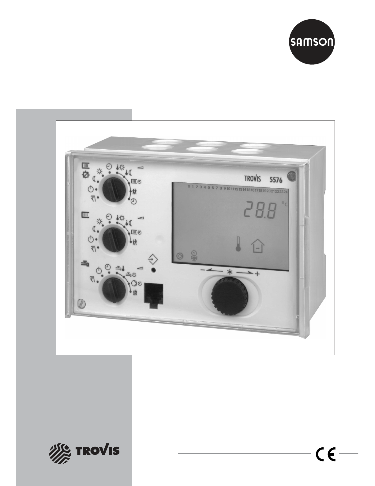
1.1.2 Rotary switches
Use the three rotary switches to adjust the required operating mode (icons on the left) and the
relevant parameters (icons on the right).
The top and middle switches are assigned to the heating circuits (see page 169). The rotary
switch in the middle is not used in systems without a second heating circuit.
The bottom switch is assigned to the DHW circuit.
Rotary switch to set the operating modes of the heating circuit
Automatic/time-controlled operation
with switchover between rated and reduced operation
Day mode (rated operation)
Night mode (reduced operation)
Control operation deactivated, frost protection only
Manual operation: correction value adjusted in percent
and activation/deactivation of the pumps
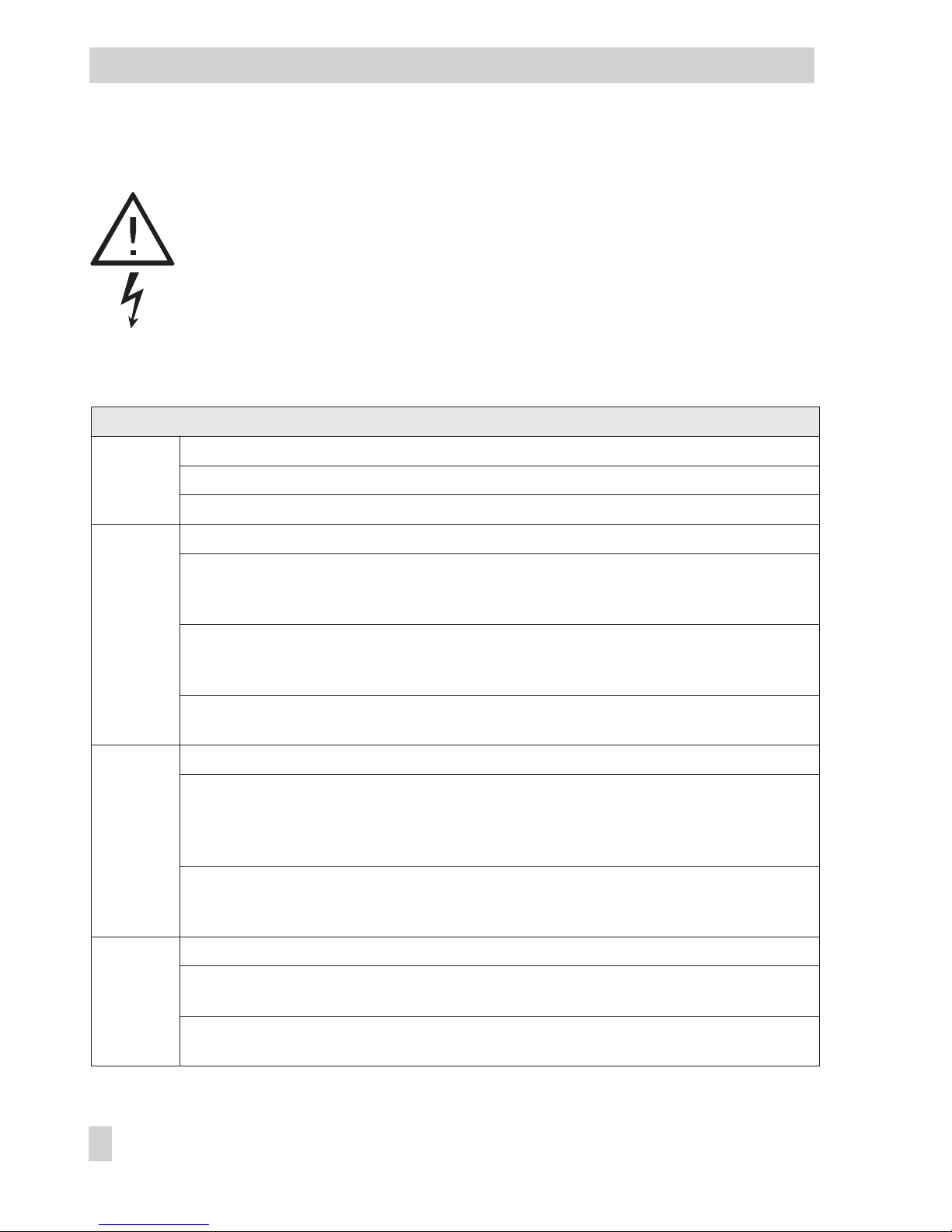
Rotary switch to set the parameters of the heating circuit
Day set point (rated room temperature)
Night set point (reduced room temperature)
Times-of-use for heating
Party mode
Controller time: setting current time, date and year
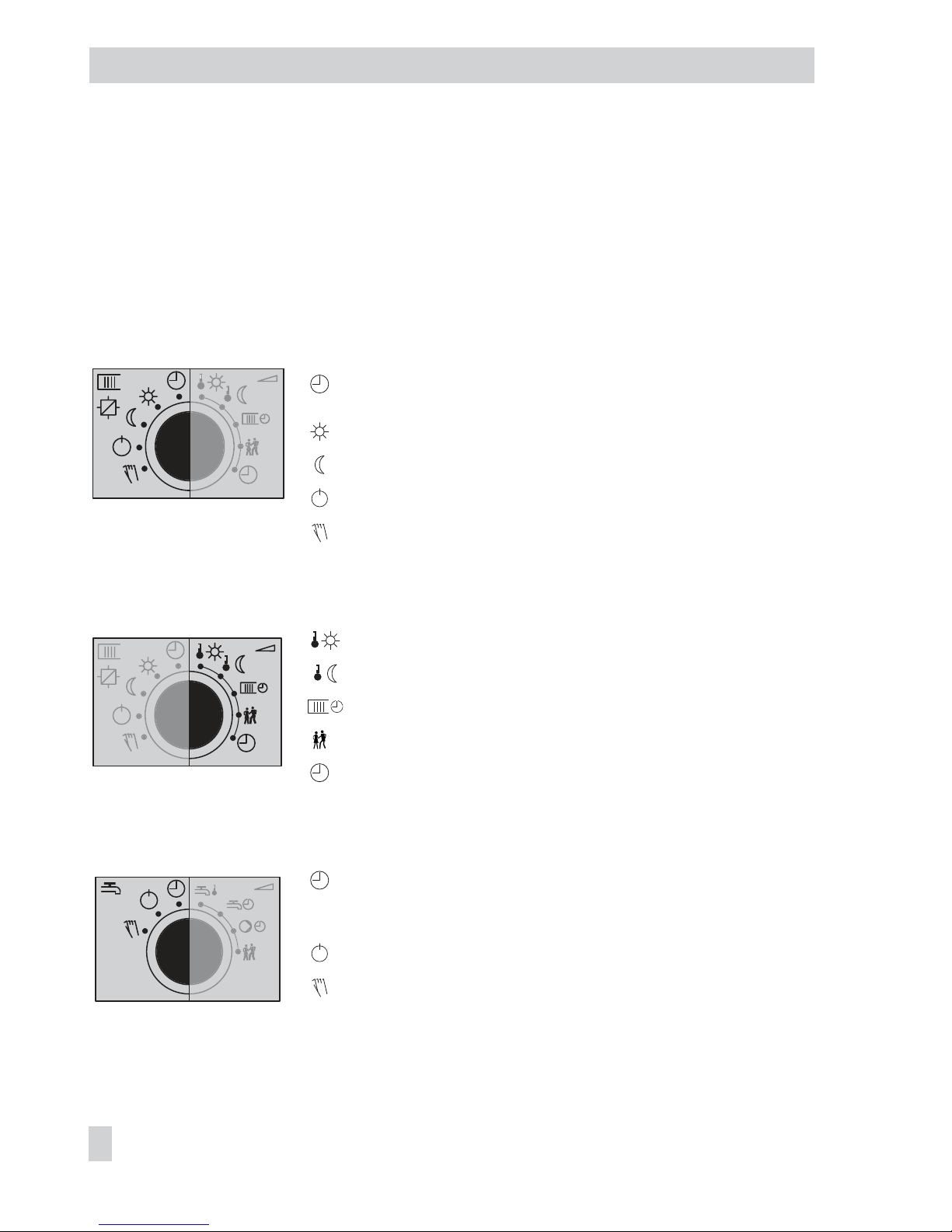
Rotary switch to set the operating modes of the DHW circuit
Automatic/time-controlled operation
with switchover between times when DHW heating
is permissible/impermissible
DHW heating deactivated, frost protection only
Manual operation: correction value adjusted in percent
and activation/deactivation of the pumps
10 EB 5576 EN
Operation
Page 11
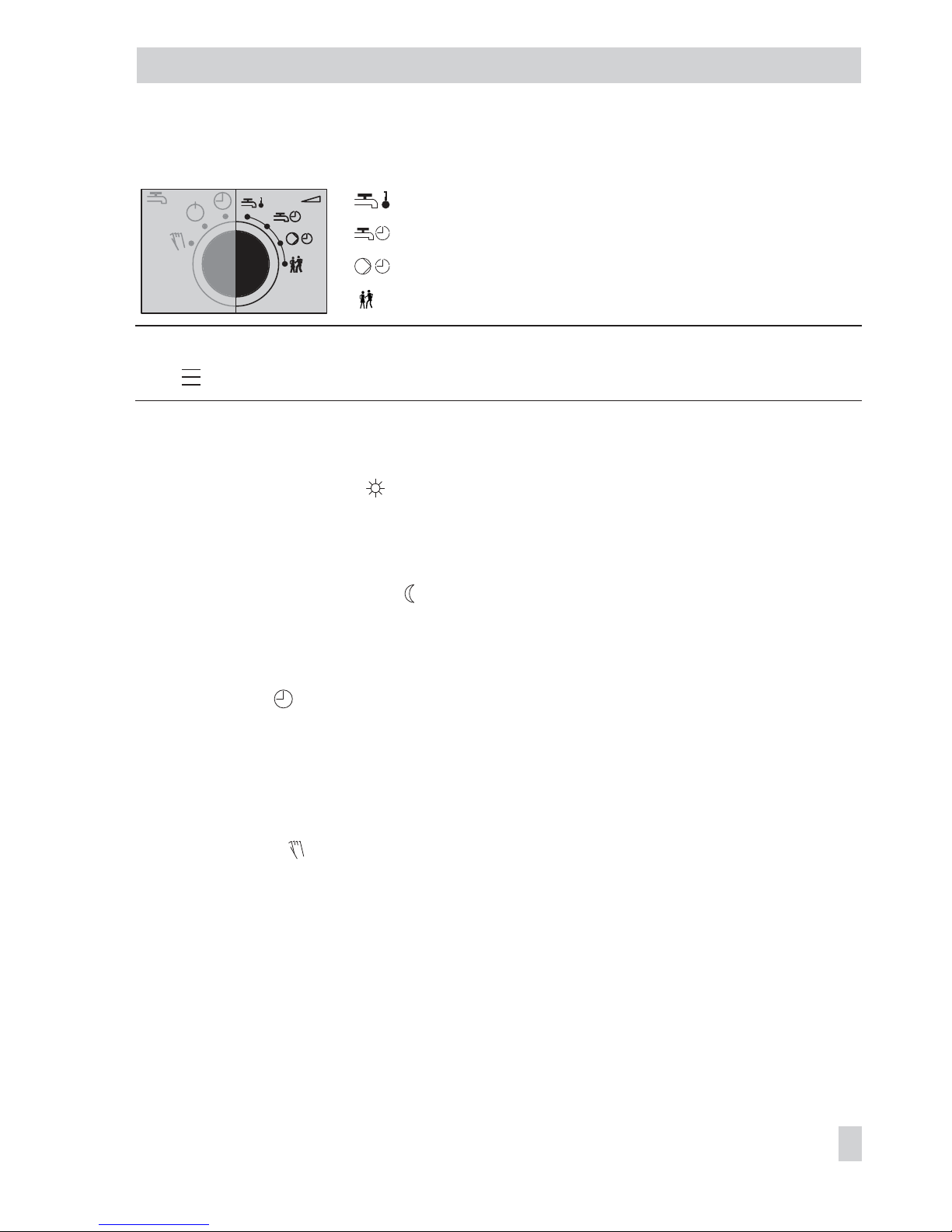
Rotary switch to set the parameters of the DHW circuit
Set point for DHW temperature
Times-of-use for DHW heating
Times-of-use for DHW circulation pump
Party mode
Note: If more than one rotary switch is set to position “Parameter“ (right side) at the same
time, blinks on the display. The controller cannot be operated.
1.2 Operating modes
Day mode (rated operation)
Regardless of the programmed times-of-use and summer mode, the set points relevant for
rated operation are used by the controller.
Night mode (reduced operation)
Regardless of the programmed times-of-use, the set points relevant for reduced operation are
used by the controller.
Automatic mode
During the programmed times-of-use, the controller works in rated operation. Outside these
times-of-use, the controller is in reduced operation, unless control operation is deactivated
depending on the outdoor temperature. The controller switches automatically between both
operating modes.
Manual operation
Valves and pumps can be controlled manually (–> section 3).
EB 5576 EN 11
Operation
Page 12
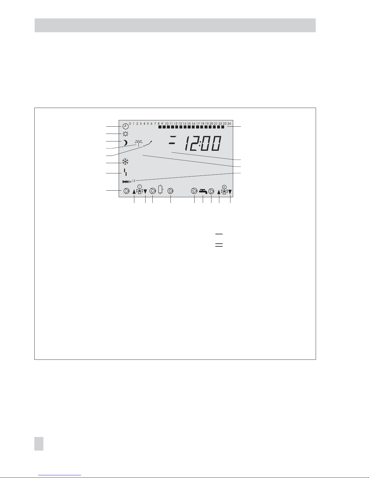
1.3 Display
During operation, the display indicates the current time as well as information about the op
eration of the controller. The times-of-use are represented by black squares below the row of
numbers at the top of the display. Icons indicate the operating status of the controller.
The controller status can be displayed in operating level (–> section 1.4).
12 EB 5576 EN
Operation
STOP
1
18
2
3
6
7
8
9
4
5
10 11 12 13 14 15 16 17
19
20
21
Fig. 1 · Icons
1 Automatic operation
2 Day mode
3 Night mode
4 Vacation mode
5 Public holiday mode
6 Frost protection
7 Operational fault
8 Output bA9
9 Valve Rk1: OPEN
10 Valve Rk1: CLOSED
11 Storage tank charging
pump SLP
12 Output BA9*
13 Circulation pump UP5*
14 DHW demand
15 Circulation pump UP2*
16 Valve Rk2: OPEN,
output bA9: ON
17 Valve Rk2: CLOSED
output bA8: ON
18 Time-of-use
19 Control circuit assignment:
: Heating circuit Rk1
: Heating circuit Rk2
20 Outdoor temperature
dependent control
deactivated
21 Demand with sequence control:
1: One output active
2: Two outputs active
* UP1, UP2, SLP, UP5, bA9 indicate possible choices for pump selection in manual mode.
Page 13
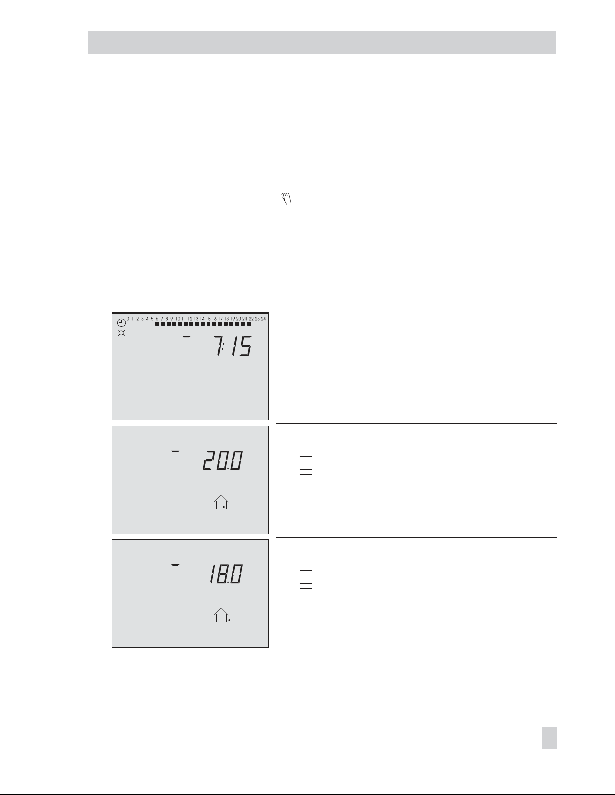
1.4 Displaying data
The time, date, public holidays and vacation periods as well as the temperatures measured
by the connected sensors and their set points can be retrieved and displayed with the help of
the rotary pushbutton.
Note: Data can also be viewed in the manual mode in the operating level.
To do so, select Info, confirm and proceed as described below.
Proceed as follows:
q
Select value.
Depending on the configuration of the controller, the different data points are displayed:
Controller time.
Room temperature
: Heating circuit Rk1
: Heating circuit Rk2
Outdoor temperature
: Heating circuit Rk1
: Heating circuit Rk2
EB 5576 EN 13
Operation
0 1 2 3 4 5 6 7 8 9 10 11 12 13 14 15 16 17 18 19 20 21 22 23 24
°C
0 1 2 3 4 5 6 7 8 9 10 11 12 13 14 15 16 17 18 19 20 21 22 23 24
°C
0 1 2 3 4 5 6 7 8 9 10 11 12 13 14 15 16 17 18 19 20 21 22 23 24
°C
Page 14
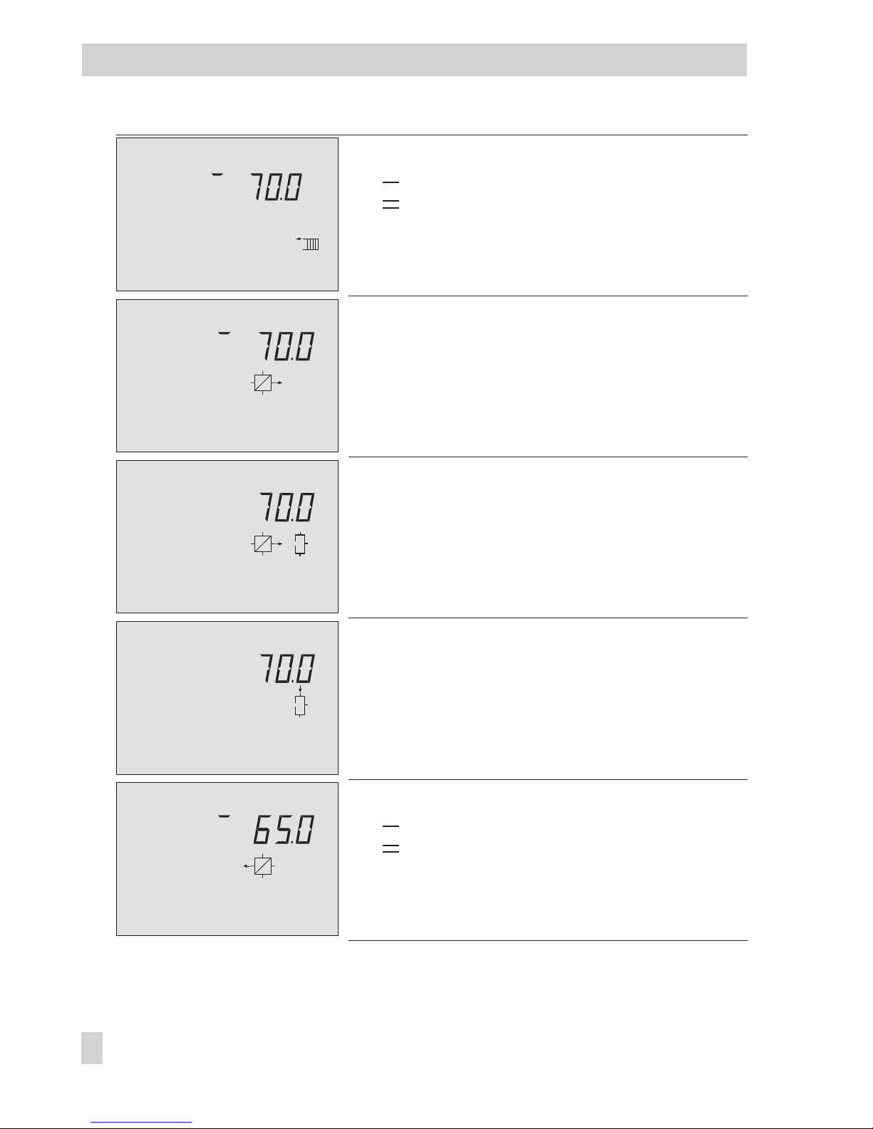
Temperature at the flow sensor VF
: Heating circuit Rk1
: Heating circuit Rk2
Temperature at the flow sensor VF1, primary exchanger
circuit
Temperature at the flow sensor VF2, DHW circuit
Temperature at the solar collector sensor VF3
Temperature at the return flow sensor RüF
: Heating circuit Rk1
: Heating circuit Rk2
14 EB 5576 EN
Operation
0 1 2 3 4 5 6 7 8 9 10 11 12 13 14 15 16 17 18 19 20 21 22 23 24
˚C
0 1 2 3 4 5 6 7 8 9 10 11 12 13 14 15 16 17 18 19 20 21 22 23 24
˚C
0 1 2 3 4 5 6 7 8 9 10 11 12 13 14 15 16 17 18 19 20 21 22 23 24
˚C
0 1 2 3 4 5 6 7 8 9 10 11 12 13 14 15 16 17 18 19 20 21 22 23 24
˚C
0 1 2 3 4 5 6 7 8 9 10 11 12 13 14 15 16 17 18 19 20 21 22 23 24
°C
0 1 2 3 4 5 6 7 8 9 10 11 12 13 14 15 16 17 18 19 20 21 22 23 24
˚C
Page 15
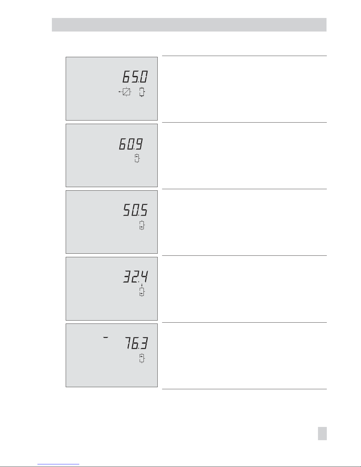
Temperature at the return flow sensor RüF, DHW circuit
Temperature at the storage tank sensor SF1 (DHW storage
tank)
Temperature at the storage tank sensor SF2 (DHW storage
tank)
Temperature at the storage tank sensor SF3 (DHW storage
tank)
Temperature at the storage tank sensor SF2, SF3 (buffer tank)
EB 5576 EN 15
Operation
0 1 2 3 4 5 6 7 8 9 10 11 12 13 14 15 16 17 18 19 20 21 22 23 24
˚C
0 1 2 3 4 5 6 7 8 9 10 11 12 13 14 15 16 17 18 19 20 21 22 23 24
°C
0 1 2 3 4 5 6 7 8 9 10 11 12 13 14 15 16 17 18 19 20 21 22 23 24
˚C
0 1 2 3 4 5 6 7 8 9 10 11 12 13 14 15 16 17 18 19 20 21 22 23 24
˚C
0 1 2 3 4 5 6 7 8 9 10 11 12 13 14 15 16 17 18 19 20 21 22 23 24
˚C
0 1 2 3 4 5 6 7 8 9 10 11 12 13 14 15 16 17 18 19 20 21 22 23 24
˚C
Page 16
Temperature at the storage tank sensor SF4 (buffer tank)
Temperature at the flow sensor VF4
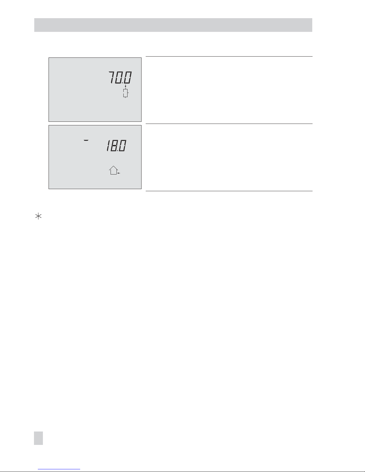
Compare set point/limit and actual value.
By pressing the rotary pushbutton when the time is displayed, the date appears on the
display.
16 EB 5576 EN
Operation
0 1 2 3 4 5 6 7 8 9 10 11 12 13 14 15 16 17 18 19 20 21 22 23 24
˚C
0 1 2 3 4 5 6 7 8 9 10 11 12 13 14 15 16 17 18 19 20 21 22 23 24
°C
Page 17
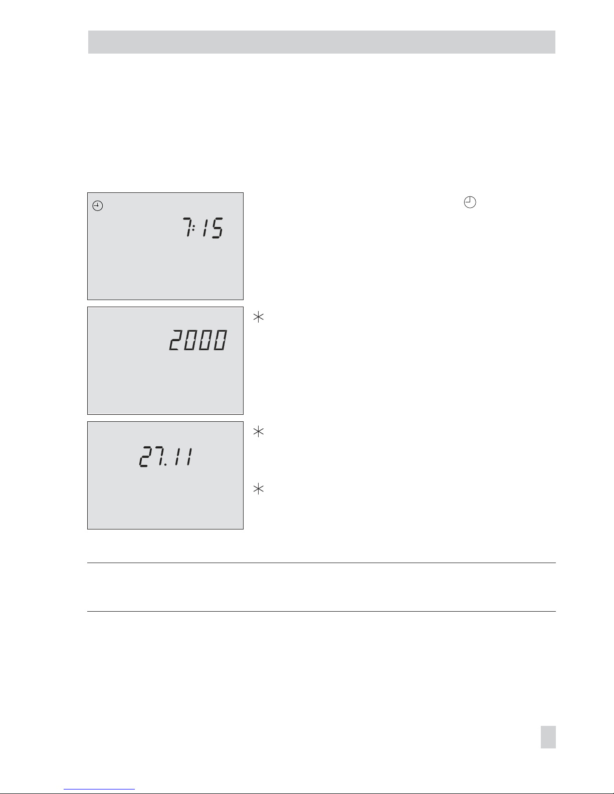
1.5 Setting the controller time
The current time and date need to be set immediately after start-up and after a power failure
of more than 24 hours has occurred. This is the case when the time blinks on the display.
Proceed as follows:
Turn the top rotary switch to position “Controller
time“ (right side).
Display shows: time
q
Edit the controller time.
Confirm the adjusted time.
Display shows: year
q
Edit the year.
Confirm the adjusted year.
Display shows: date (day.month)
q
Edit the date.
Confirm the adjusted date.
Display shows: time
Return the rotary switch to the desired operating mode
(left side).
Note: The correct time is guaranteed after a power failure of 24 hours. Normally, the correct
time is still retained at least 48 hours after a power failure.
EB 5576 EN 17
Operation
2423222120191817161514131211109876543210
0 1 2 3 4 5 6 7 8 9 10 11 12 13 14 15 16 17 18 19 20 21 22 23 24
242322212019181716151413121110
9876543210
Page 18

1.6 Setting the times-of-use
Three times-of-use can be set for each day of the week.
If only one time-of-use is required, the start and stop times of the second time-of-use must be
set to identical times. In this case, the third time-of-use is not displayed.
If only two times-of-use are required, the start and stop times of the third time-of-use must be
set to identical times.
The times-of-use for the different control circuits are set at the rotary switches one after the
other:
Times-of-use Rotary switch Position
Heating circuit 1* Top
Heating circuit 2* Middle
DHW heating* Bottom
Circulation pump Bottom
* Refer to page 169 for assignment
Parameters
WE* Range of values
Period/day 1–7 1–7, 1, 2, 3, 4, 5, 6, 7 with 1–7 = every day,
1 = Monday, 2 = Tuesday, ..., 7 = Sunday
Start first time-of-use 6:00 0:00 to 24:00h; in steps of 15 minutes
Stop first time-of-use 22:00 0:00 to 24:00h; in steps of 15 minutes
Start second time-of-use 22:15 0:00 to 24:00h; in steps of 15 minutes
Stop second time-of-use 22:15 0:00 to 24:00h; in steps of 15 minutes
Start third time-of-use – 0:00 to 24:00h; in steps of 15 minutes
Stop third time-of-use – 0:00 to 24:00h; in steps of 15 minutes
* Default values (WE) valid for heating circuit 1/primary heat exchanger circuit (top rotary switch)
18 EB 5576 EN
Operation
Page 19
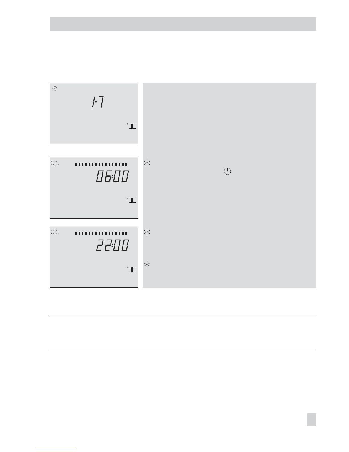
Proceed as follows: Turn appropriate rotary switch to position
“Times-of-use”.
Display shows: 1–7
q
Select period/day for which the times-of-use are to be
valid:
1–7 = every day,
1 = Monday, 2 = Tuesday, ..., 7 = Sunday
Activate editing mode for period/day.
Display shows: START, blinks
q
Edit start time (steps of 15 minutes).
Confirm start time.
Display shows: STOP
q Edit stop time (steps of 15 minutes).
Confirm stop time.
Display shows:
START
The second time-of-use is set like the first time-of-use.
To set the times-of-use for each day, repeat the instructions in the fields highlighted in gray.
Return the rotary switch to the desired operating mode (left side).
Note: Do not use the 1–7 menu to check the programmed times-of-use.
If this menu is opened after the times-of-use have been set, the schedule programmed for
Monday is also adopted for all other days of the week.
EB 5576 EN 19
Operation
0 1 2 3 4 5 6 7 8 9 10 11 12 13 14 15 16 17 18 19 20 21 22 23 24
ST OP
0 1 2 3 4 5 6 7 8 9 10 11 12 13 14 15 16 17 18 19 20 21 22 23 24
ST A RT
0 1 2 3 4 5 6 7 8 9 10 11 12 13 14 15 16 17 18 19 20 21 22 23 24
Page 20

1.7 Setting the party mode
Using the Party mode function, the controller continues or activates the rated operation of the
controller during the time when the party timer is active, regardless of the programmed
times-of-use. The party timer begins when the rotary switch has been returned to operating
mode “Automatic“. When the party timer has elapsed, the party timer is reset to 00:00.
The party modes for the different control circuits are set at the rotary switches one after the
other:
Party timer Rotary switch Position
Heating circuit 1* Top
Heating circuit 2* Middle
DHW circuit* Bottom
* Refer to page 169 for assignment
Parameter
WE Range of values
Continue/activate rated operation 0 h 0 to 48 hours
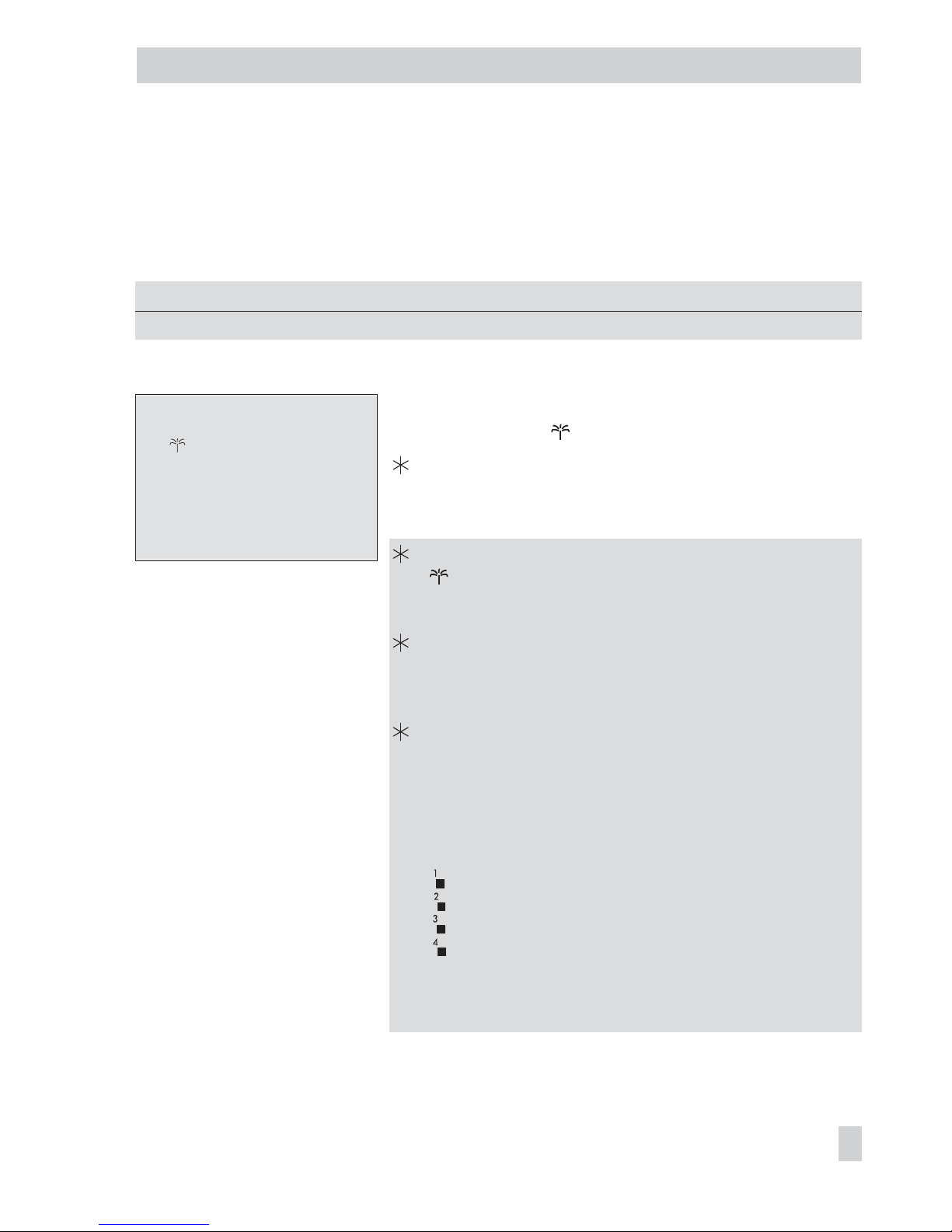
Proceed as follows:
Turn appropriate rotary switch to “Party mode“.
Display shows: 00:00 or the remaining time of the party timer
q
Edit desired length of the one-off time-of-use.
Return the rotary switch to operating mode “Automatic“ (left side).
Note: The party timer counts down in steps of 15 minutes.
20 EB 5576 EN
Operation
Page 21

1.8 Activating extended operating level
After the key number 1999 has been entered, the following information can be viewed and
edited after the data points listed in section 1.4 have been displayed:
4
Heat capacity
4
Flow rate
4
Public holidays (can be changed)
4
Vacation periods (can be changed)
4
Valve positions
4
Modem status information
4
Meter bus status information
4
Switching states of the binary inputs
4
Info 2 · The following data are shown in the same sequence as shown below:
Controller ID (refer to section 8.6)
Memory capacity of data logging module (section 9.5)
Modbus station address (refer to section 9.2)
Operating hours of solar circuit pump (refer to section 6.4)
Water flow sensor (refer to section 6.3)
Opening the extended operating level:
Switch to configuration and parameter level.
Display shows:
0 0 0 0
q
Set key number 1999.
Confirm key number.
Display shows: time
Note:
–
The additional information is hidden when the key number 1999 is entered again.
–
The key number 1999 cannot be used to change the controller configuration and
parameterization. A separate key number exists for configuration and parameterization.
Refer to section 2.
EB 5576 EN 21
Operation
Page 22

1.8.1 Setting public holidays
On public holidays, the times-of-use specified for Sunday apply. A maximum of 20 public
holidays may be entered.
Parameter
WE Level / Range of values
Public holidays – Extended operating level / 01.01 (1 Jan) to 31.12 (31 Dec)
Proceed as follows:
q
In extended operating level, select “Public holidays“.
Display shows:
Open data point for public holidays.
q
If applicable, select – – – –.
Activate editing mode for public holiday. blinks.
q
Edit desired public holiday.
Confirm public holiday.
To enter additional public holidays, re-select – – – – and repeat the steps in the fields highlighted in gray.
Exit data point for public holidays.
Note: Public holidays can also be entered in parameter level PA5 (–> section 2.3).
Deleting a public holiday:
q
Under data point for public holidays, select the holiday you wish to delete.
Confirm selection.
q
Select – – – – .
Delete the public holiday.
Note: Public holidays that are not assigned to a specific date should be deleted by the end of
the year so that they are not carried on into the following year.
22 EB 5576 EN
Operation
0 1 2 3 4 5 6 7 8 9 10 11 12 13 14 15 16 17 18 19 20 21 22 23 24
Page 23
1.8.2 Setting vacation periods
During vacation periods, the controller constantly remains in reduced operating mode. A
maximum of 10 vacation periods can be entered. Each vacation period can be separately
assigned to the heating circuits Rk1 and Rk2 and/or the DHW circuit.
Parameters
WE Level / Range of values
Vacation period (START, STOP) – Extended operating level / 01.01 to 31.12
Proceed as follows:
q
In extended operating level, select “Vacation periods“.
Display shows:
Open data point for vacation periods.
Display shows:
START, – –.– – (day.month)
q
If applicable, select – – – – .
Activate editing mode for start date of vacation period.
blinks.
q Edit start date of vacation period.
Confirm start date of the vacation period.
Display shows: STOP, – –.– – (day.month)
q
Edit end of vacation period.
Confirm end of vacation period.
Black squares under 1 to 4 at the top of the display
indicate the assignment of the vacation periods to the
individual control circuits.
q
Select the control circuit to which the current vacation
period should apply.
Current vacation period applies to circuit Rk1
Current vacation period applies to circuit Rk2
–
Current vacation period applies to DHW circuit
The vacation period can be assigned to a single control
circuit or any combination of all three control circuits
(Rk1 and Rk2, DHW circuit).
To enter additional vacation periods, re-select
– – – – and repeat the steps in the fields
highlighted in gray.
EB 5576 EN 23
Operation
0 1 2 3 4 5 6 7 8 9 10 11 12 13 14 15 16 17 18 19 20 21 22 23 24
Page 24

Exit data point for vacation periods.
Note: Vacation periods can also be entered in parameter level PA5 (–> section 2.3).
Deleting vacation periods:
q
Under data point for vacation periods, select the start date of the period you wish to de
-
lete.
Confirm selection.
q
Select – – – – .
Delete vacation period.
Note: Vacation periods should be deleted by the end of the year so that they are not carried
on into the following year.
24 EB 5576 EN
Operation
Page 25

1.9 Setting room and DHW temperature set points
For the heating circuits, the desired room temperatures during the day (Day set point) and
during the night (Night set point) can be entered into the controller.
In the DHW circuit, the temperature you wish the DHW to be heated to can be set.
The temperature set points for the different control circuits are set at the rotary switches one
after the other:
Desired temperature set point Switch Position
Heating circuit 1*: Day set point Top
Heating circuit 1*: Night set point Top
Heating circuit 2*: Day set point Middle
Heating circuit 2*: Night set point Middle
DHW circuit*: DHW temperature set point Bottom
* Refer to page 169 for assignment
Parameters
WE Rotary switch / Range of values
Day set point 20 °C Top, middle / –5 to 150 °C
Night set point 15 °C Top, middle / –5 to 150 °C
DHW temperature set point 60 °C Bottom / Min. to max. DHW temperature
Proceed as follows:
Turn appropriate rotary switch to “Set point temperature“.
Display shows: temperature
q
Set temperature value.
Return the rotary switch to the desired operating mode (left side).
EB 5576 EN 25
Operation
Page 26
26 EB 5576 EN
Operation
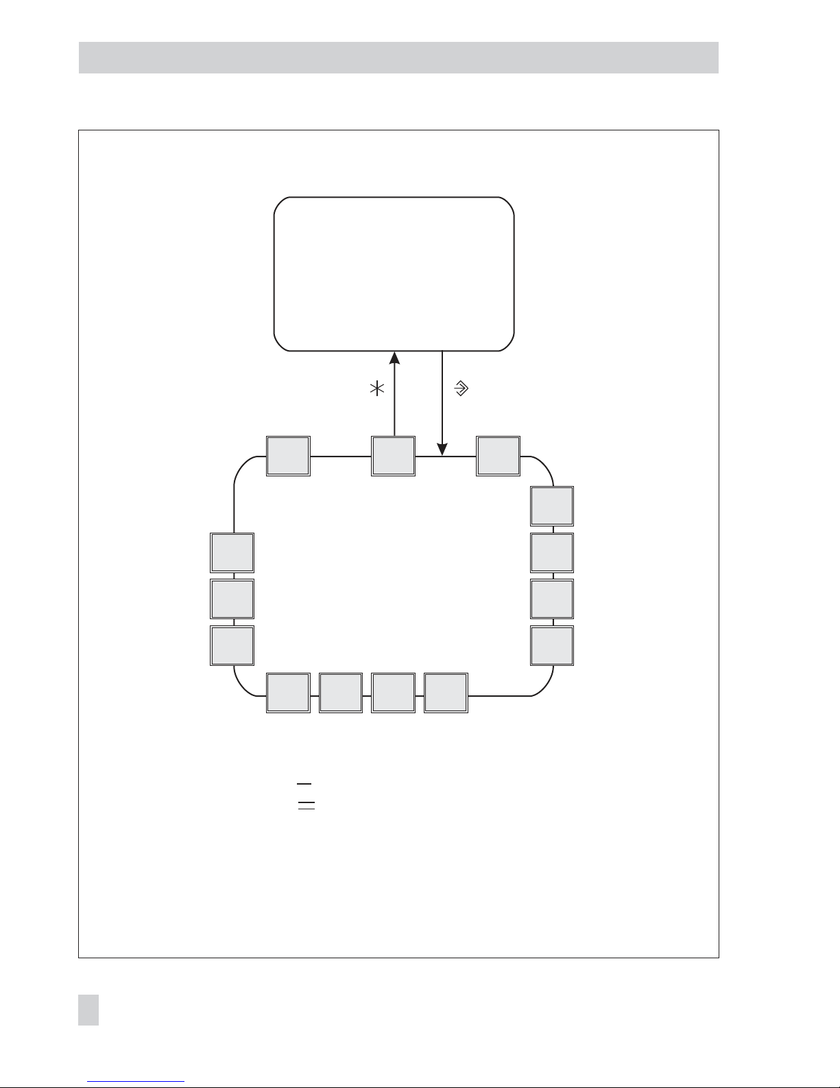
Fig. 2 · Level structure of TROVIS 5576
q
Configuration and
parameter level
(start-up, see section 2)
PA4
PA5
PA6
CO7
CO6
CO1
PA2
Anl
CO2CO4CO5
End PA1
CO8
q
Operating level
(display of time and
operation, see section 1)
& key number
PA1/CO1: Heating circuit Rk1 ( )
PA2/CO2: Heating circuit Rk2 ( )
PA4/CO4: DHW heating
PA5/CO5: System-wide parameters
PA6/CO6: Communication parameters/
Modbus/meter bus communication
CO7: Device bus
CO8: Initialization of free
inputs
Anl: System code number
Page 27

2 Start-up
The modifications of the controller configuration and parameter settings described in this sec
-
tion can only be performed after the valid key number has been entered.
The valid key number for initial start-up can be found on page 191. To avoid unauthorized
use of the key number, remove the page or make the key number unreadable. In addition, it
is possible to enter a new, customized key number (–> section 7.20).
2.1 Setting the system code number
Various hydraulic schematics are available. Each system configuration is represented by a
system code number. The different schematics are dealt with in section 4. Available controller
functions are described in sections 5, 6 and 7.
Changing the system code number resets previously adjusted function blocks to their default
settings (WE). Function block parameters and parameter level settings remain unchanged.
The system code number is set in the configuration level.
Proceed as follows:
Switch to configuration and parameter level.
Display shows: 0 0 0 0
q
Set valid key number.
Confirm key number.
Display shows: PA1
q
Select Anl (-> Fig. 2).
Activate editing mode for the system code number.
q
Edit system code number.
Confirm system code number.
Display shows: End
Return to operating level.
EB 5576 EN 27
Start-up
Page 28

2.2 Activating and deactivating functions
A function is activated or deactivated in the associated function block. The numbers 0 to 24
in the top row of the display represent the respective function block numbers. When a config
uration level is opened, the activated function blocks are indicated by a black square on the
right-hand side below the function block number. For more details on function blocks, refer to
section 12.1.
The functions are grouped by topics:
4
CO1: Heating circuit Rk1 ( )
4
CO2: Heating circuit Rk2 ( )
4
CO3: Not used
4
CO4: DHW heating
4
CO5: System-wide functions
4
CO6: Modbus and meter bus communication
4
CO7: Device bus
4
CO8: Initialization of free inputs
Proceed as follows:
Switch to configuration and parameter level.
Display shows: 0 0 0 0
q
Set valid key number.
Confirm key number.
Display shows: PA1
q
Select configuration level (-> Fig. 2).
Open configuration level.
q
Select function block.
Activated function blocks are marked by “- 1“.
Deactivated function blocks are marked by “- 0“.
Activate editing mode for the function block.
F__ blinks.
q
Activate the function block.
Display shows:
F__ - 1
An activated function block is indicated by a black square below (right) the function
block number in the top row of the controller display.
Or:
28 EB 5576 EN
Start-up
Page 29

q
Deactivate the function block.
Display shows: F__ - 0
Confirm settings.
If the function block is not closed, further function block parameters can be adjusted.
Proceed as follows:
Make the desired changes and confirm.
If applicable, the next function block parameter is displayed.
Confirm all parameters to exit the opened function block.
To adjust additional function blocks, repeat the steps in the fields highlighted in gray.
q
Select End.
Exit configuration level.
q
Select End.
Return to operating level.
Note: All function block settings are saved in the non-volatile memory of the controller.
2.3 Changing parameters
Depending on the set system code number and the activated functions, not all parameters
listed in the parameter list in the Appendix (–> section 12.2) might be available.
The parameters are grouped by topics:
4
PA1: Heating circuit Rk1 ( )
4
PA2: Heating circuit Rk2 ( )
4
PA3: Not used
4
PA4: DHW heating
4
PA5: Parameters for various systems
4
PA6: Communication parameters
4
PA7: Not used
4
PA8: Not used
EB 5576 EN 29
Start-up
Page 30

Proceed as follows:
Switch to configuration and parameter level.
Display shows: 0 0 0 0
q
Set valid key number.
Confirm key number.
Display shows: PA1
q
Select parameter level (-> Fig. 2).
Open parameter level.
q
Select desired parameter.
Activate editing mode for the parameter.
q
Edit the parameter.
Confirm the parameter.
To adjust additional parameters, repeat the steps in the fields highlighted in gray.
q Select End.
Exit parameter level.
q Select End.
Return to the operating level.
Note: All function block settings are saved in the non-volatile memory of the controller.
2.4 Calibrating sensors
The connected sensors are calibrated in configuration level CO5.
The following applies:
4
CO5 -> F01 - 1, CO5 -> F02 - 0, CO5 -> F03 - 0: Pt 1000 (Pt 100) sensors (default)
4
CO5 -> F01 - 0, CO5 -> F02 - 0, CO5 -> F03 - 0: PTC (Pt 100) sensors
4
CO5 -> F01 - 0, CO5 -> F02 - 1, CO5 -> F03 - 0: NTC (Pt 100) sensors
4
CO5 -> F01 - 1, CO5 -> F02 - 1, CO5 -> F03 - 0: Ni 1000 (Pt 100) sensors
4
CO5 -> F01 - 0, CO5 -> F02 - 0, CO5 -> F03 - 1: Pt 500 (Pt 100) sensors
The resistance values of the sensors can be found on page 170.
If the temperature values displayed at the controller differ from the actual temperatures, the
measured values of all connected sensors can be changed or readjusted. To calibrate a sen
-
30 EB 5576 EN
Start-up
Page 31

sor, the currently displayed sensor value must be changed such that it matches the tempera
ture (reference temperature) measured directly at the point of measurement.
Sensor calibration is to be activated in CO5 via function block F20.
An incorrect sensor calibration can be deleted by setting F20 - 0.
Proceed as follows:
Switch to configuration and parameter level. Display shows:
0 0 0 0
q
Set valid key number.
Confirm key number. Display shows: PA1
q
Select CO5 configuration level.
Open CO5 configuration level.
q
Select function block F20.
Activate editing mode for function block F20.
q Select appropriate sensor icon:
Room sensor
: Heating circuit Rk1
: Heating circuit Rk2
Outdoor sensor
: Heating circuit Rk1
: Heating circuit Rk2
EB 5576 EN 31
Start-up
0 1 2 3 4 5 6 7 8 9 10 11 12 13 14 15 16 17 18 19 20 21 22 23 24
°C
0 1 2 3 4 5 6 7 8 9 10 11 12 13 14 15 16 17 18 19 20 21 22 23 24
°C
Page 32

Flow sensor VF
: Heating circuit Rk1
: Heating circuit Rk2
Flow sensor VF1, primary heat exchanger circuit
Flow sensor VF2, DHW circuit
Solar collector sensor VF3
Return flow sensor RüF
: Heating circuit Rk1
: Heating circuit Rk2
32 EB 5576 EN
Start-up
0 1 2 3 4 5 6 7 8 9 10 11 12 13 14 15 16 17 18 19 20 21 22 23 24
˚C
0 1 2 3 4 5 6 7 8 9 10 11 12 13 14 15 16 17 18 19 20 21 22 23 24
˚C
0 1 2 3 4 5 6 7 8 9 10 11 12 13 14 15 16 17 18 19 20 21 22 23 24
˚C
0 1 2 3 4 5 6 7 8 9 10 11 12 13 14 15 16 17 18 19 20 21 22 23 24
˚C
0 1 2 3 4 5 6 7 8 9 10 11 12 13 14 15 16 17 18 19 20 21 22 23 24
°C
Page 33

Return flow sensor RüF, DHW circuit
Storage tank sensor SF1 (DHW storage tank)
Storage tank sensor SF2 (DHW storage tank)
Storage tank sensor SF3 (DHW storage tank)
EB 5576 EN 33
Start-up
0 1 2 3 4 5 6 7 8 9 10 11 12 13 14 15 16 17 18 19 20 21 22 23 24
°C
0 1 2 3 4 5 6 7 8 9 10 11 12 13 14 15 16 17 18 19 20 21 22 23 24
˚C
0 1 2 3 4 5 6 7 8 9 10 11 12 13 14 15 16 17 18 19 20 21 22 23 24
˚C
0 1 2 3 4 5 6 7 8 9 10 11 12 13 14 15 16 17 18 19 20 21 22 23 24
˚C
Page 34

Storage tank sensor SF2, SF3 (buffer tank)
Storage tank sensor SF4 (buffer tank)
Flow sensor VF4
Display measured value.
Measured value blinks.
q
Correct measured value.
Read the actual temperature directly from the thermometer at the point of measurement
and enter this value as the reference temperature.
Confirm corrected measured value.
Additional sensors are calibrated similarly.
q
Select End.
Exit configuration level.
q
Select End.
Return to operating level.
34 EB 5576 EN
Start-up
0 1 2 3 4 5 6 7 8 9 10 11 12 13 14 15 16 17 18 19 20 21 22 23 24
˚C
0 1 2 3 4 5 6 7 8 9 10 11 12 13 14 15 16 17 18 19 20 21 22 23 24
˚C
0 1 2 3 4 5 6 7 8 9 10 11 12 13 14 15 16 17 18 19 20 21 22 23 24
˚C
Page 35

2.5 Resetting to default values
All parameters in parameter levels PA1, PA2 and PA5 set over the rotary switches, except
for the maximum flow temperature and the return flow temperature limits in PA1/PA2, can
be reset to their default settings (WE).
Proceed as follows:
Switch to configuration and parameter level.
q
Set key number 1991.
Confirm key number.
EB 5576 EN 35
Start-up
Page 36

3 Manual operation
Switch to manual mode to configure all outputs (see wiring diagram in section 11).
The manual operation for the different control circuits is set at the rotary switches:
Manual operation Rotary switch Position
Heating circuit 1* Top
Heating circuit 2* Middle
DHW heating* Bottom
* Refer to page 169 for assignment
Proceed as follows:
Turn appropriate rotary switch to position “Manual operation“.
q
Select:
POS_ : Correction value in percent
UP_: Activation of the circulation pump
SLP: Activation of the storage tank charging pump
Confirm selection.
Display blinks.
q
Edit the correction value or activate/deactivate the circulation pump, etc.
Confirm edited settings.
The modified values remain active as long as the controller is in manual mode.
Return the rotary switch to the desired operating mode (left side).
Manual operation of the selected control circuit is deactivated by switching to any other
operating mode.
Note: Simply setting the rotary switch to position “Manual operation“ has no influence on
the outputs. You have to actually enter a correction value or activate/deactivate the pumps to
configure the outputs.
In manual mode, frost protection (–> section 7.2) cannot be activated.
36 EB 5576 EN
Manual operation
BE
BA
AE
AA
BE
BA
AE
AA
RüF1 VF1UP1RK1/Y1 RK1/Y1RF1 VF1UP1 RüF1 RF1
BE
BA
AE
AA
WW
KW
SF1SLP
BE
BA
AE
AA
WW
KW
SF1SLP
1.
Primary system
Secondary system
Primary system
2.
Secondary system
Page 37

4 Systems
Various hydraulic schematics are available.
The systems can be configured both as primary and secondary systems. The fundamental hy
-
draulic differences between a primary and a secondary system are illustrated in Fig. 3.
4
1. A mixing valve replaces the heat exchanger in the heating/DHW circuit
4
2. A storage tank charging pump replaces the primary solenoid/thermoelectric valve
The controller settings do not have to be changed.
EB 5576 EN 37
Systems
Single-stage
boiler
Fig. 3 · Differences between primary and secondary systems
Page 38

Boiler systems:
Single-stage boiler systems can be configured to include any system whose heating circuits
and DHW circuit include just one heat exchanger. These systems are Anl 1.0, 1.5 to 1.8,
2.x, 3.x, 4.0 to 4.3, 7.x, 8.x and 16.x.
The boiler can be controlled by an on/off output (CO1 -> F12 - 0).
38 EB 5576 EN
Systems
RK1/Y1 RüF1 VF1 UP1 RF1
BE
BA
AE
AA
RK1_on/off VF1 UP1 RF1
BE
BA
AE
AA
Fig. 4 · Configuration of a boiler system
Page 39
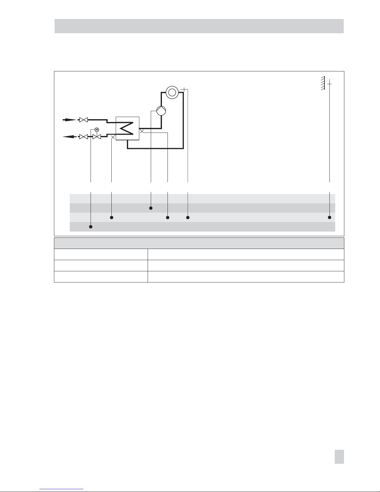
System Anl 1.0
Default settings
CO1 -> F01 - 0 (without RF1)
CO1 -> F02 - 1 (with AF1)
CO1 -> F03 - 1 (with RüF1)
EB 5576 EN 39
Systems
BE
BA
AE
AA
AF1RüF1 VF1UP1RK1/Y1 RF1
Page 40
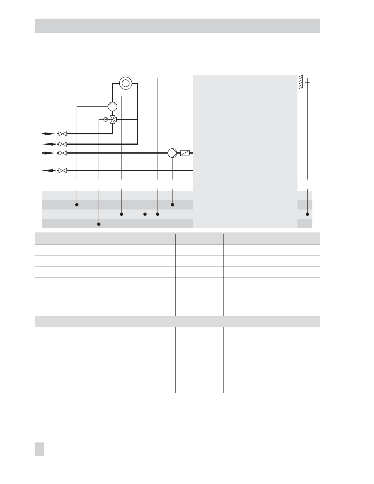
Systems Anl 1.1 to 1.4
System Anl 1.1 Anl 1.2 Anl 1.3 Anl 1.4
Type of DHW heating Type 1 Type 2 Type 3 Type 4
1)
XX = SLP UP2 SLP UP2
Integration of flow sensor VF4 Possible Possible Possible Possible
ZP integration (broken line)
with CO4 -> F10 - 1
– Not possible – Not possible
Note –
Only second
-
ary system
–
Only second
-
ary system
Default settings
CO1 -> F01 - 0 (w/o RF1) - 0 (w/o RF1) - 0 (w/o RF1) - 0 (w/o RF1)
CO1 -> F02 - 1 (with AF1) - 1 (with AF1) - 1 (with AF1) - 1 (with AF1)
CO1 -> F03 - 1 (with RüF1) - 0 (w/o RüF1) - 1 (with RüF1) - 0 (w/o RüF1)
CO4 -> F01 - 1 (with SF1) - 1 (with SF1) - 1 (with SF1) - 1 (with SF1)
CO4 -> F02 - 0 (w/o SF2) - 1 (with SF2) - 0 (w/o SF2) - 1 (with SF2)
CO4 -> F05 - 0 (w/o VF4) - 0 (w/o VF4) - 0 (w/o VF4) - 0 (w/o VF4)
40 EB 5576 EN
Systems
UP1 XX
1)
AF1 RK1/Y1 VF1 RüF1 RF1
BE
BA
AE
AA
DHW
heating
Unfold back cover!
Page 41
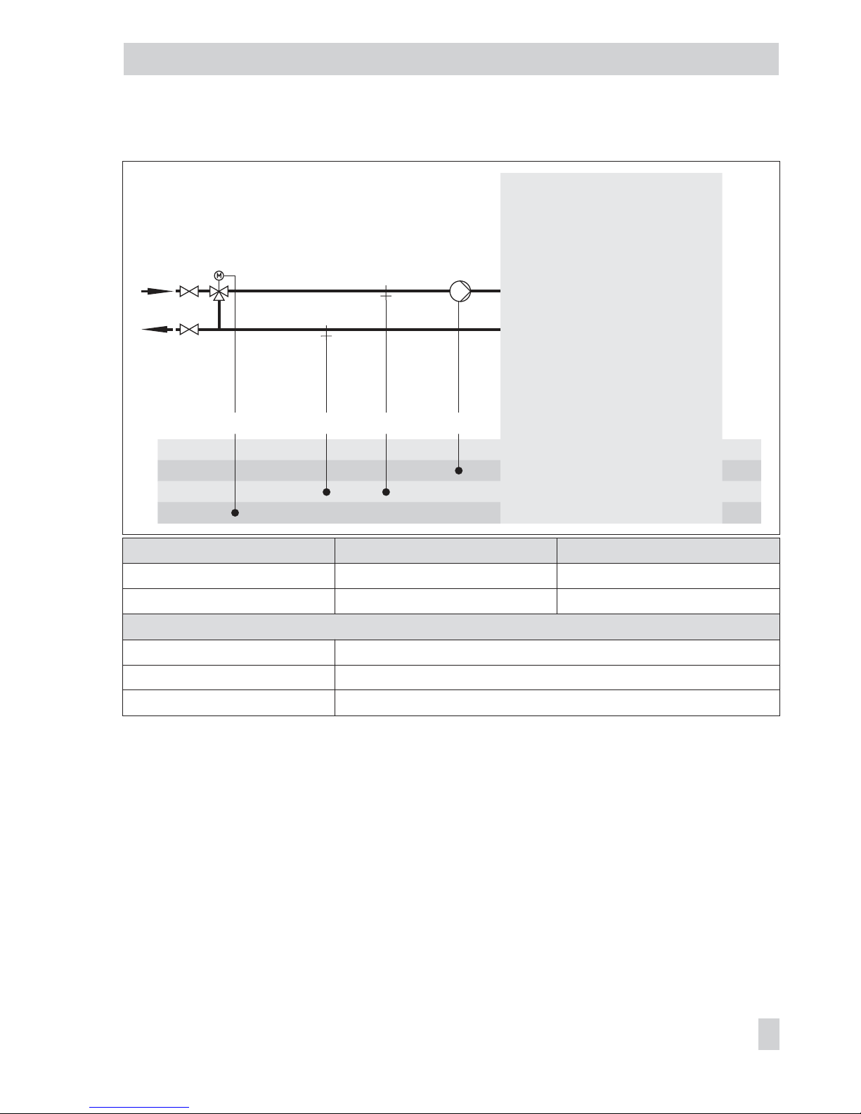
Systems Anl 1.5 and 1.7
System Anl 1.5 Anl 1.7
Type of DHW heating Type 1 Type 3
Integration of flow sensor VF4 Not possible Not possible
Default settings
CO1 -> F03 - 1 (with RüF1)
CO4 -> F01 - 1 (with SF1)
CO4 -> F02 - 0 (without SF2)
EB 5576 EN 41
Systems
BE
BA
AE
AA
SLPRüF1 VF1RK1/Y1
DHW
heating
Unfold back cover!
Page 42

Systems Anl 1.6 and 1.8
System
Anl 1.6
With pre-control
Anl 1.8
With pre-control
Anl 1.6
W/o pre-control
Anl 1.8
W/o pre-control
Type of DHW heating Type 2 Type 4 Type 2 Type 4
Integration of VF4, UP1 • –
ZP integration (broken line)
with CO4 -> F10 - 1
Possible Possible
Note –
VF1 takes the position of VF4;
RüF1 is to be installed in the heat
exchanger
Default settings
CO1 -> F03 - 1 (with RüF1)
CO4 -> F01 - 1 (with SF1)
CO4 -> F02 - 1 (with SF2)
CO4 -> F05 - 0 (without VF4)
42 EB 5576 EN
Systems
BE
BA
AE
AA
RüF1RK1/Y1
UP1 VF1
DHW
heating
Unfold back cover!
Page 43

System Anl 1.9
System
Anl 1.9
With pre-control
Anl 1.9
Without pre-control
Integration of VF4, UP2 Yes No
Note
–
VF2 takes the position of VF4
Default settings
CO4 -> F01 - 0 (without SF1)
CO4 -> F03 - 0 (without RüF2)
CO4 -> F04 - 0 (without water flow sensor at BE17)
CO4 -> F05 - 0 (without VF4)
EB 5576 EN 43
Systems
BE
BA
AE
AA
RK2/Y2
UP2 VF2
WW
KW
ZP
VF4
BE17
SF1
RüF2
Page 44
System Anl 2.0
Default settings
CO1 -> F01 - 0 (without RF1)
CO1 -> F02 - 1 (with AF1)
CO1 -> F03 - 1 (with RüF1)
CO4 -> F01 - 1 (with SF1)
CO4 -> F02 - 0 (without SF2)
44 EB 5576 EN
Systems
BE
BA
AE
AA
WW
KW
AF1ZP RüF1 VF1 UP1
SLP (Rk2) SF1RK1/Y1 RF1
Page 45

Systems Anl 2.1 to 2.4
System Anl 2.1 Anl 2.2 Anl 2.3 Anl 2.4
Type of DHW heating Type 1 Type 2 Type 3 Type 4
1)
XX = SLP UP2 SLP UP2
Integration of flow sensor VF4 Not possible Possible Not possible Possible
ZP integration (broken line)
with CO4 -> F10 - 1
– Not possible – Not possible
Default settings
CO1 -> F01 - 0 (w/o RF1) - 0 (w/o RF1) - 0 (w/o RF1) - 0 (w/o RF1)
CO1 -> F02 - 1 (with AF1) - 1 (with AF1) - 1 (with AF1) - 1 (with AF1)
CO1 -> F03 - 1 (with RüF1) - 1 (with RüF1) - 1 (with RüF1) - 1 (with RüF1)
CO4 -> F01 - 1 (with SF1) - 1 (with SF1) - 1 (with SF1) - 1 (with SF1)
CO4 -> F02 - 0 (w/o SF2) - 1 (with SF2) - 0 (w/o SF2) - 1 (with SF2)
CO4 -> F05 - 0 (w/o VF4) - 0 (w/o VF4)
EB 5576 EN 45
Systems
BE
BA
AE
AA
AF1
RüF1 VF1
UP1RK1/Y1 RF1
XX
1)
DHW-
heating
Unfold back cover!
Page 46

System Anl 3.0
Default settings
CO1 -> F02 - 1 (with AF1)
CO1 -> F03 - 1 (with RüF1)
CO2 -> F01 - 0 (without RF2)
CO2 -> F03 - 0 (without RüF2)
46 EB 5576 EN
Systems
BE
BA
AE
AA
AF1RüF1 VF1 UP2
RK2/Y2RK1/Y1
RF2
VF2
RüF2UP1 UP1
Page 47

Systems Anl 3.1 to 3.4
System Anl 3.1 Anl 3.2 Anl 3.3 Anl 3.4
Type of DHW heating Type 1 Type 2 Type 3 Type 4
1)
XX = SLP UP1 SLP UP1
Integration of flow sensor VF4 Not possible Possible Not possible Possible
ZP integration (broken line)
with CO4 -> F10 - 1
– Possible – Not possible
Note –
–
Binary output
BA9 replaced
by UP1
Only 0 to 10 V
output signal
available (Y2)
Default settings
CO1 -> F02 - 1 (with AF1) - 1 (with AF1) - 1 (with AF1) - 1 (with AF1)
CO1 -> F03 - 1 (with RüF1) - 1 (with RüF1) - 1 (with RüF1) - 1 (with RüF1)
CO2 -> F01 - 0 (w/o RF2) - 0 (w/o RF2) - 0 (w/o RF2) - 0 (w/o RF2)
CO2 -> F03 - 0 (w/o RüF2) - 0 (w/o RüF2) - 0 (w/o RüF2) - 0 (w/o RüF2)
CO4 -> F01 - 1 (with SF1) - 1 (with SF1) - 1 (with SF1) - 1 (with SF1)
CO4 -> F02 - 0 (w/o SF2) - 1 (with SF2) - 0 (w/o SF2) - 1 (with SF2)
CO4 -> F05 - 0 (w/o VF4) - 0 (w/o VF4)
EB 5576 EN 47
Systems
BE
BA
AE
AA
AF1
RüF1
VF1
UP2
RK2/Y2RK1/Y1
RF2
VF2
RüF2 XX
1)
DHW
heating
Unfold back cover!
Page 48

System Anl 3.5
Note
Control and UP1 are only active during processing for external
demand.
Default setting
CO1 -> F03 - 1 (with RüF1)
48 EB 5576 EN
Systems
BE
BA
AE
AA
RüF1 VF1
RK1/Y1 UP1
Page 49

System Anl 4.0
Default settings
CO1 -> F01 - 0 (without RF1)
CO1 -> F02 - 1 (with AF1)
CO1 -> F03 - 1 (with RüF1)
CO2 -> F01 - 0 (without RF2)
CO2 -> F02 - 0 (without AF2)
CO2 -> F03 - 0 (without RüF2)
EB 5576 EN 49
Systems
BE
BA
AE
AA
AF1
RüF1
VF1
UP2
RK2/Y2RK1/Y1
RF2
VF2
RüF2
RF1
UP1
Page 50

Systems Anl 4.1 to 4.3
System Anl 4.1 Anl 4.2 Anl 4.3
Type of DHW heating Type 1 Type 2 Type 3
1)
XX = SLP BA9 SLP
Integration of VF4 Not possible Possible Not possible
ZP integration (broken line)
with CO4 -> F10 - 1
– Not possible –
Note –
Only 0 to 10 V output signal available (Y2)
Default settings
CO1 -> F01 - 0 (w/o RF1) - 0 (w/o RF1) - 0 (w/o RF1)
CO1 -> F02 - 1 (with AF1) - 1 (with AF1) - 1 (with AF1)
CO1 -> F03 - 1 (with RüF1) - 1 (with RüF1) - 1 (with RüF1)
CO2 -> F01 - 0 (w/o RF2) - 0 (w/o RF2) - 0 (w/o RF2)
CO2 -> F02 - 0 (w/o AF2) - 0 (w/o AF2) - 0 (w/o AF2)
CO2 -> F03 - 0 (w/o RüF2) - 0 (w/o RüF2) - 0 (w/o RüF2)
CO4 -> F01 - 1 (with SF1) - 1 (with SF1) - 1 (with SF1)
CO4 -> F02 - 0 (w/o SF2) - 1 (with SF2) - 0 (w/o SF2)
CO4 -> F05 - 0 (w/o VF4)
50 EB 5576 EN
Systems
BE
BA
AE
AA
AF1RüF1
VF1
UP2
RK2/Y2RK1/Y1
RF2
VF2
RüF2 RF1UP1
XX1)
DHW heating
Unfold
back cover!
Page 51

System Anl 4.5
Default settings
CO1 -> F01 - 0 (without RF1)
CO1 -> F02 - 1 (with AF1)
CO1 -> F03 - 1 (with RüF1)
CO2 -> F01 - 0 (without RF2)
CO2 -> F02 - 0 (without AF2)
CO2 -> F03 - 0 (without RüF2)
CO4 -> F01 - 1 (with SF1)
CO4 -> F02 - 0 (without SF2)
EB 5576 EN 51
Systems
BE
BA
AE
AA
AF1
RüF1
VF1
UP2
RK2/Y2RK1/Y1
RF2
VF2
RüF2
RF1
UP1
WW
KW
SF1SLP ZP
Page 52
Systems Anl 7.1 and 7.2
System Anl 7.1 Anl 7.2
Type of DHW heating Type 1 Type 2
1)
XX = SLP UP2
Integration of VF4 Not possible Possible
ZP integration (broken line)
with CO4 -> F10 - 1
– Possible
Default settings
CO1 -> F03 - 1 (with RüF1) - 1 (with RüF1)
CO4 -> F01 - 1 (with SF1) - 1 (with SF1)
CO4 -> F02 - 0 (without SF2) - 1 (with SF2)
CO4 -> F03 - 0 (without RüF2) - 0 (without RüF2)
CO4 -> F05 - 0 (without VF4)
52 EB 5576 EN
Systems
BE
BA
AE
AA
RüF1 VF1
RK2/Y2RK1/Y1
VF2 RüF2
XX1)UP1 UP1
DHW
heating
Unfold back cover!
Page 53

Systems Anl 8.1 and 8.2
System Anl 8.1 Anl 8.2
Type of DHW heating Type 1 Type 2
1)
XX = SLP UP2
Integration of VF4 Not possible Possible
ZP integration (broken line)
with CO4 -> F10 - 1
– –
Default settings
CO1 -> F01 - 0 (without RF1) - 0 (without RF1)
CO1 -> F02 - 1 (with AF1) - 1 (with AF1)
CO1 -> F03 - 1 (with RüF1) - 1 (with RüF1)
CO4 -> F01 - 1 (with SF1) - 1 (with SF1)
CO4 -> F02 - 0 (without SF2) - 1 (with SF2)
CO4 -> F03 - 0 (without RüF2) - 0 (without RüF2)
CO4 -> F05 - 0 (without VF4)
EB 5576 EN 53
Systems
BE
BA
AE
AA
AF1
RüF1
VF1
UP1
RK1/Y1 RF1
RK2/Y2
VF2 RüF2
XX1)
DHW heating
Unfold back cover!
Page 54
System Anl 10.0
Default settings
CO1 -> F01 - 0 (without RF1)
CO1 -> F02 - 1 (with AF1)
CO1 -> F03 - 1 (with RüF1)
CO2 -> F01 - 0 (without RF2)
CO2 -> F02 - 0 (without AF2)
CO2 -> F03 - 1 (with RüF2)
54 EB 5576 EN
Systems
BE
BA
AE
AA
AF1RüF1
VF1
UP1RK1/Y1
RF1
RüF2
VF2 UP2
RK2/Y2 RF2
Page 55
Systems Anl 10.1 to 10.3
System Anl 10.1 Anl 10.2 Anl 10.3
Type of DHW heating Type 1 Type 2 Type 3
1)
XX = SLP BA9 SLP
Integration of VF4 Possible Possible Possible
ZP integration (broken line)
with CO4 -> F10 - 1
– Not possible –
Note
–
Only 0 to 10 V output signal available (Y2)
Only second. system
Default settings
CO1 -> F01 - 0 (w/o RF1) - 0 (w/o RF1) - 0 (w/o RF1)
CO1 -> F02 - 1 (with AF1) - 1 (with AF1) - 1 (with AF1)
CO1 -> F03 - 1 (with RüF1) - 0 (w/o RüF1) - 1 (with RüF1)
CO2 -> F01 - 0 (w/o RF2) - 0 (w/o RF2) - 0 (w/o RF2)
CO2 -> F02 - 0 (w/o AF2) - 0 (w/o AF2) - 0 (w/o AF2)
CO2 -> F03 - 1 (with RüF2) - 0 (w/o RüF2) - 1 (with RüF2)
CO4 -> F01 - 1 (with SF1) - 1 (with SF1) - 1 (with SF1)
CO4 -> F02 - 0 (w/o SF2) - 1 (with SF2) - 0 (w/o SF2)
CO4 -> F05 - 0 (w/o VF4) - 0 (w/o VF4) - 0 (w/o VF4)
EB 5576 EN 55
Systems
BE
BA
AE
AA
UP1 XX
1)
AF1 RK1/Y1
VF1
RüF1
RF1
UP2
RK2/Y2
VF2
RüF2
RF2
DHW heating
Unfold
back cover!
Page 56

System Anl 10.5
Default settings
CO1 -> F01 - 0 (without RF1)
CO1 -> F03 - 1 (with RüF1)
CO2 -> F01 - 0 (without RF1)
CO2 -> F03 - 1 (with RüF2)
56 EB 5576 EN
Systems
BE
BA
AE
AA
RüF1 VF1RK1/Y1
RüF2 VF2RK2/Y2
UP1
UP2
Page 57

Systems Anl 11.0 and 11.3
System Anl 11.0 Anl 11.3
Type of DHW heating Type 1 Type 3
Integration of VF4 Not possible Not possible
ZP integration (broken line)
with CO4 -> F10 - 1
– –
Note
–
Binary output BA9
replaced by UP2
Default settings
CO1 -> F01 - 0 (without RF1)
CO1 -> F02 - 1 (with AF1)
CO1 -> F03 - 1 (with RüF1)
CO4 -> F03 - 0 (without RüF2)
EB 5576 EN 57
Systems
BE
BA
AE
AA
AF1RüF1 RüF2
VF1
UP1RK1/Y1
RF1
RK2/Y2
DHW heating
Unfold back cover!
Page 58

System Anl 11.1
Default settings
CO1 -> F01 - 0 (without RF1)
CO1 -> F02 - 1 (with AF1)
CO1 -> F03 - 1 (with RüF1)
CO4 -> F01 - 1 (with SF1)
CO4 -> F02 - 0 (without SF2)
CO4 -> F03 - 0 (without RüF2)
The system code Anl 11.1 can also be used for systems with buffer tank. See page 60.
58 EB 5576 EN
Systems
BE
BA
AE
AA
WW
KW
UP1 RK1/Y1 VF1 RüF1 RF1 AF1 ZP SLPRüF2 VF2 SF1RK2/Y2
Page 59

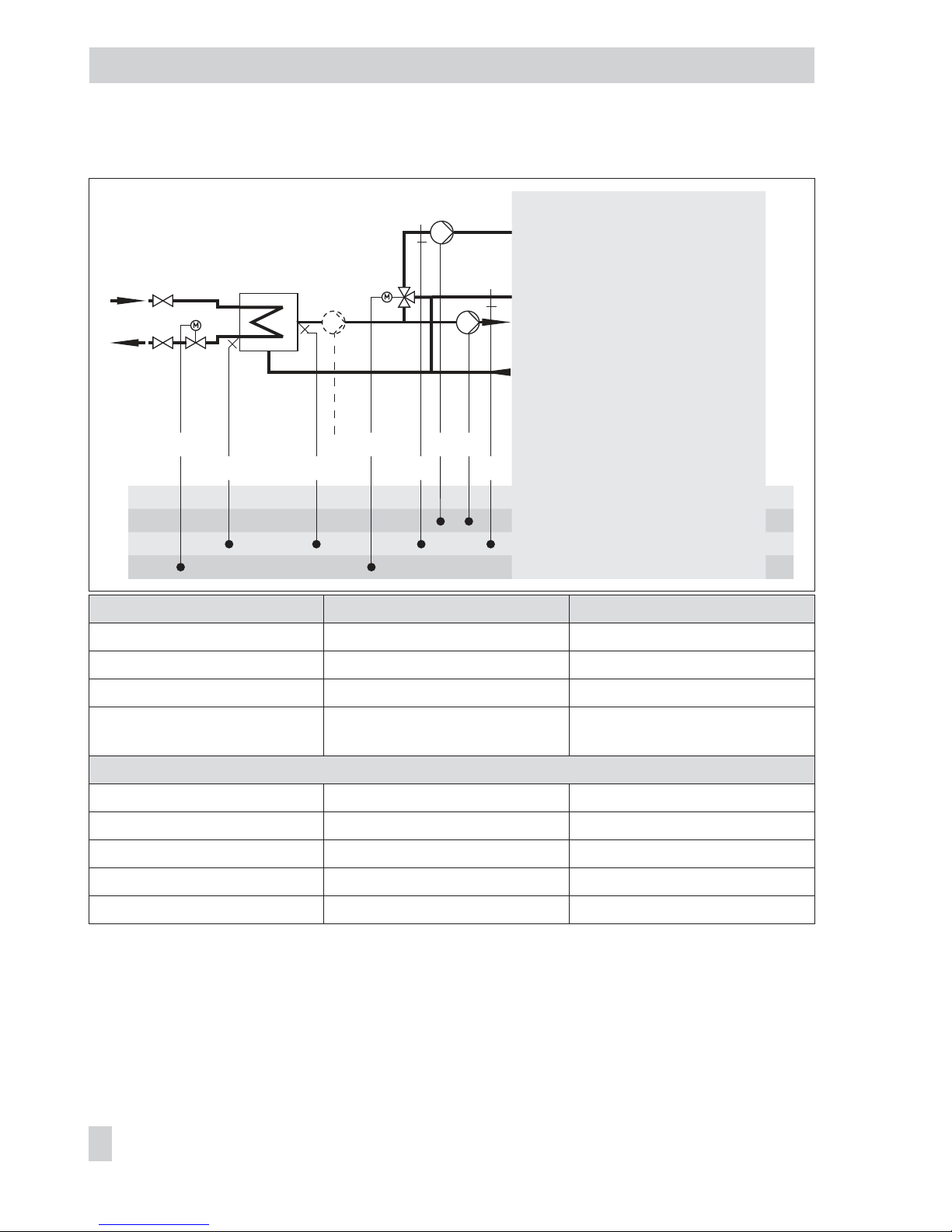
System Anl 11.2
System
Anl 11.2
With pre-control
Anl 11.2
Without pre-control
Type of DHW heating Type 2 Type 2
Integration of VF4, UP2 • –
ZP integration (broken line)
with CO4 -> F10 - 1
Possible Possible
Note
–
VF2 takes the position of VF4
Default settings
CO1 -> F01 - 0 (without RF1)
CO1 -> F02 - 1 (with AF1)
CO1 -> F03 - 1 (with RüF1)
CO4 -> F01 - 1 (with SF1)
CO4 -> F02 - 1 (with SF2)
CO4 -> F03 - 0 (without RüF2)
CO4 -> F05 - 0 (without VF4)
The system code Anl 11.2 can also be used for systems with buffer tank. See page 60.
EB 5576 EN 59
Systems
BE
BA
AE
AA
WW
KW
AF1
SF2
ZP SLPRüF1
VF1 VF4
RüF2UP1
SF1
RK1/Y1
RK2/Y2 RF1
UP2
VF2
Page 60

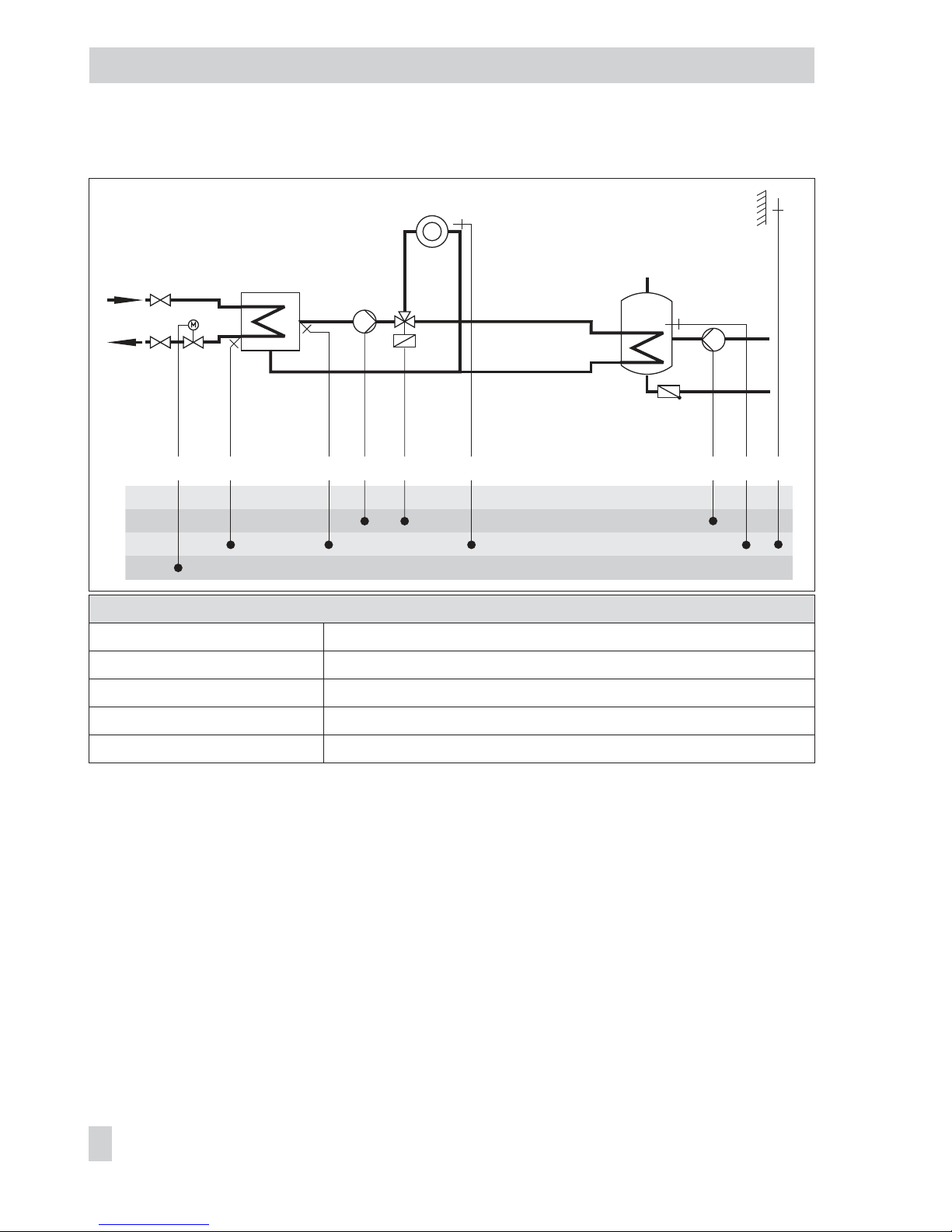
System Anl 11.1/11.2 with buffer tank
Default settings
CO1 -> F01 - 0 (without RF1)
CO1 -> F02 - 1 (with AF1)
CO1 -> F03 - 1 (with RüF1)
CO4 -> F01 - 1 (with SF1)
CO4 -> F02
Anl 11.1 - 0 (without SF2)
Anl 11.2 - 1 (with SF2)
CO4 -> F03 - 0 (without RüF2)
60 EB 5576 EN
Systems
WW
KW
BE
BA
AE
AA
AF1
RüF2
VF2RK2 ZP SF1
SF2SLP RK1 RF1VF1
RüF1UP1
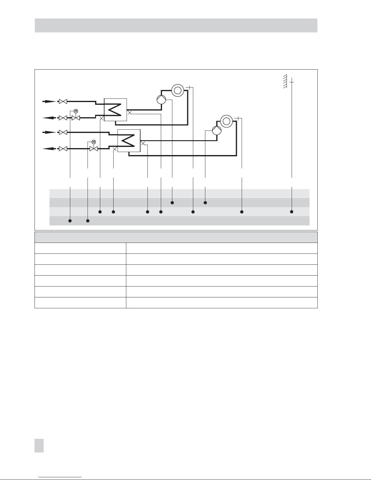
Page 61

System Anl 11.4
ZP integration (broken line)
with CO4 -> F10 - 1
Possible
Default settings
CO1 -> F01 - 0 (without RF1)
CO1 -> F02 - 1 (with AF1)
CO1 -> F03 - 1 (with RüF1)
CO4 -> F01 - 1 (with SF1)
CO4 -> F02 - 1 (with SF2)
CO4 -> F03 - 0 (without RüF2)
The system code Anl 11.4 can also be used for systems with buffer tank. See page 62.
EB 5576 EN 61
Systems
BE
BA
AE
AA
SLPRüF1
VF1 VF2
AF1
RüF2UP1RK1/Y1
RK2/Y2 RF1
WW
KW
SF1ZP
UP2 SF3 SF2
VF3
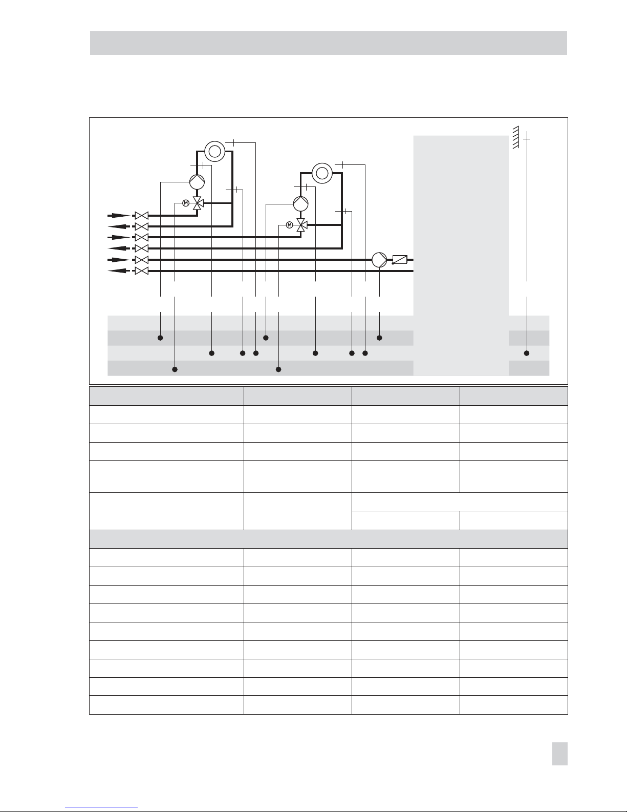
Page 62

System Anl 11.4 with buffer tank
Default settings
CO1 -> F01 - 0 (without RF1)
CO1 -> F02 - 1 (with AF1)
CO1 -> F03 - 1 (with RüF1)
CO4 -> F01 - 1 (with SF1)
CO4 -> F02 - 1 (with SF2)
CO4 -> F03 - 0 (without RüF2)
62 EB 5576 EN
Systems
WW
KW
BE
BA
AE
AA
AF1RüF2
VF2
VF3
RK2 ZP
SF1
SF2
SF3SLP
RK1UP2 RF1VF1
RüF1UP1
Page 63

System Anl 11.5
Note DHW circuit with adjustable valve position for storage tank charging
in absolute priority operation. By using RüF2, the ready-adjusted
valve position is governed by the return flow temperature limitation.
Default settings
CO1 -> F01 - 0 (without RF1)
CO1 -> F02 - 1 (with AF1)
CO4 -> F02 - 0 (without SF2)
CO4 -> F03 - 1 (with RüF2)
EB 5576 EN 63
Systems
BE
BA
AE
AA
RK1/Y1
RüF1
VF1 UP1 AF1
RF1
WW
KW
ZP
RüF2
SF1
RK2
Page 64
System Anl 11.6
*Note: The pump in the DHW circuit is designed to run constantly. There-
fore, it must connected directly to the mains supply.
Default settings
CO1 -> F01 - 0 (without RF1)
CO1 -> F02 - 1 (with AF1)
CO1 -> F03 - 1 (with RüF1)
CO4 -> F01 - 1 (with SF1)
CO4 -> F02 - 1 (with SF2)
CO4 -> F03 - 0 (without RüF2)
64 EB 5576 EN
Systems
BE
BA
AE
AA
WW
KW
Z
RK1/Y1
VF2VF1 SF2 UP1 AF1
RüF2 SLP/ZP SF1 RF1
*
RK2/Y2
RüF1
Page 65

System Anl 11.9
System
Anl 11.9
With pre-control
Anl 11.9
Without pre-control
Integration of VF4, UP2 Yes No
Note
–
VF2 takes the position of VF4
Default settings
CO1 -> F01 - 0 (without RF1)
CO1 -> F02 - 1 (with AF1)
CO1 -> F03 - 1 (with RüF1)
CO4 -> F01 - 0 (without SF1)
CO4 -> F03 - 0 (without RüF2)
CO4 -> F04 - 0 (without water flow sensor at BE17)
CO4 -> F05 - 0 (without VF4)
EB 5576 EN 65
Systems
BE
BA
AE
AA
AF1
RüF1
VF1
UP1RK1/Y1
RK2/Y2 RF1
UP2
VF2
WW
KW
ZP
VF4
BE17
SF1
RüF2
Page 66

Systems Anl 14.1 and 14.2
System Anl 14.1 Anl 14.2
Type of DHW heating Type 1 Type 2
1)
XX = SLP UP1
Integration of UP1 Possible Not possible
Default settings
CO1 -> F02 - 1 (with AF1) - 1 (with AF1)
CO1 -> F03 - 1 (with RüF1) - 1 (with RüF1)
CO4 -> F01 - 1 (with SF1) - 1 (with SF1)
CO4 -> F02 - 0 (w/o SF2) - 1 (with SF2)
66 EB 5576 EN
Systems
BE
BA
AE
AA
RÜF1
XX1) RK1/Y1 VF2
BA8 BA9
UP1
AF1
VF1
SF3UP2
DHW
heating
Unfold
back
cover!
Page 67

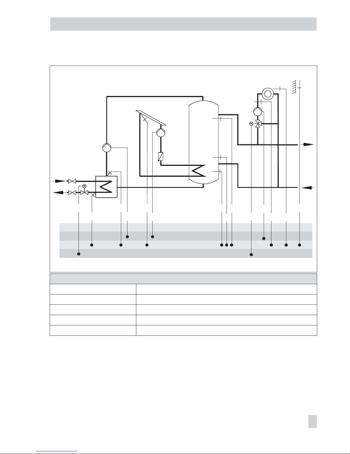
System Anl 14.3
Default settings
CO1 -> F02 - 1 (with AF1)
CO1 -> F03 - 1 (with RüF1)
CO4 -> F01 - 1 (with SF1)
EB 5576 EN 67
Systems
BE
BA
AE
AA
RÜF1
SLP RK1/Y1
BA8 BA9
AF1VF1
RÜF2
ZP UP1SF3
SF4/VF4SF1 UP2
SF2
KW
WW
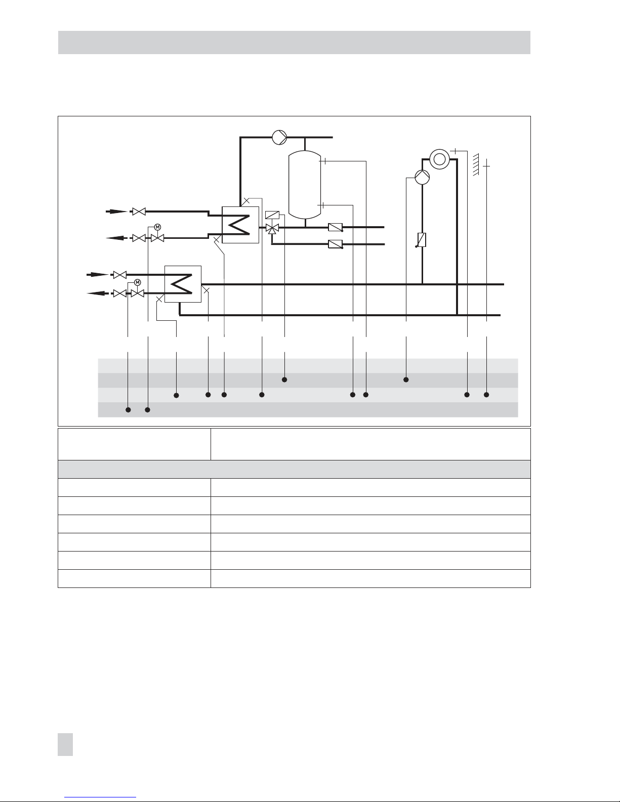
Page 68

System Anl 16.0
Default settings
CO1 -> F02 - 1 (with AF1)
CO1 -> F03 - 1 (with RüF1)
68 EB 5576 EN
Systems
BE
BA
AE
AA
SF2
SF1RüF1 SLP
VF1RK1/Y1 UP1 AF1
Page 69

System Anl 16.1
Default settings
CO1 -> F02 - 1 (with AF1)
CO1 -> F03 - 1 (with RüF1)
CO2 -> F01 - 0 (without RF2)
CO2 -> F02 - 0 (without AF2 for Rk2)
CO2 -> F03 - 0 (without RüF2)
EB 5576 EN 69
Systems
BE
BA
AE
AA
SF2
SF1RüF1 SLP
VF1RK1/Y1 UP1 AF1
RK2/Y2
UP2
VF2
RüF2
RF2
Page 70

System Anl 16.2
Default settings
CO1 -> F02 - 1 (with AF1)
CO1 -> F03 - 1 (with RüF1)
70 EB 5576 EN
Systems
BE
BA
AE
AA
SF2
SF1RüF1
SLP
VF1RK1/Y1 UP1 AF1
VF2
UP2
Page 71

System Anl 16.3
Default settings
CO1 -> F02 - 1 (with AF1)
CO1 -> F03 - 1 (with RüF1)
EB 5576 EN 71
Systems
BE
BA
AE
AA
SF3
SF1
SLP
VF1RK1/Y1 AF1
UP1
RüF2
BA9
SF2
RüF1
Page 72

System Anl 16.4
Default settings
CO1 -> F02 - 1 (with AF1)
CO1 -> F03 - 1 (with RüF1)
72 EB 5576 EN
Systems
BE
BA
AE
AA
SF3
SF2RüF1
SLP
VF1RK1/Y1 AF1
VF2
UP2
UP1
RüF2
BA9
SF1
Page 73
System Anl 16.6
Default settings
CO1 -> F02 - 1 (with AF1)
CO1 -> F03 - 1 (with RüF1)
CO2 -> F01 - 0 (without RF2)
CO2 -> F02 - 0 (without AF2 for Rk2)
CO2 -> F03 - 0 (without RüF2)
EB 5576 EN 73
Systems
BE
BA
AE
AA
SF3
SF1
RüF1
SLP
VF1RK1/Y1 AF1
RK2/Y2
UP2
VF2
RF2
RüF2
UP1
SF2
Page 74

5 Functions of the heating circuit
Which controller functions are available depends on the selected system code number (Anl).
5.1 Weather-compensated control
When weather-compensated control is used, the flow temperature is controlled according to
the outdoor temperature. The heating characteristic in the controller defines the flow tempera
ture set point as a function of the outdoor temperature (–> Fig. 5). The outdoor temperature
required for weather-compensated control can either be measured at an outdoor sensor or
received over the 0 to 10 V input or from a connected device bus.
Functions
WE Configuration
Outdoor sensors AF1/2 1 CO1, 2 -> F02 - 1
Outdoor temperature received
over 0 to 10 V input
0
AE
–20 °C
50 °C
CO5 -> F23 - 1
Direction/AE for receiving temperature
Lower transmission range / –50 to 100 °C
Upper transmission range / –50 to 100 °C
If you wish to alternatively receive the outdoor temperature over the device bus, the follow
-
ing additional configurations must be made:
Device bus 0 CO7 -> F01 - 1; device bus address
Receive value AF1 0 CO7 -> F07 - 1; register no.
74 EB 5576 EN
Functions of the heating circuit
20
30
0.2
2.4
2.62.93.2
2.2
2.0
1.8
1.6
1.4
1.2
1.0
0.8
0.4
0.6
40
50
60
70
80
90
100
110
120
130
[°C]
–20
[°C]–16–12–8–4048121620
140
150
–24 –28 –32 –36 –40
t
VL
t
A
Fig. 5 · Gradient characteristics
t
VL
Flow temperature
t
A
Outdoor temperature
Page 75

Receive value AF2 0 CO7 -> F09 - 1; register no.
5.1.1 Gradient characteristic
Basically, the following rule applies: a decrease in the outdoor temperature causes the flow
temperature to increase.
By varying the parameters Gradient and Level, you can adapt the characteristic to your indi
-
vidual requirements:
The gradient needs to be increased if the room temperature
drops when it is cold outside.
The gradient needs to be decreased if the room tempera-
ture rises when it is cold outside.
The level needs to be increased and the gradient decreased
if the room temperature drops when it is mild outside.
EB 5576 EN 75
Functions of the heating circuit
t
VL
t
A
[°C]
[°C]
20 0 –20
t
VL
t
A
[°C]
[°C]
20 0 –20
t
VL
t
A
[°C]
[°C]
20 0 –20
Page 76

The level needs to be decreased and the gradient increased
if the room temperature rises when it is mild outside.
Outside the times-of-use, reduced set points are used for control:
The reduced flow set point is calculated as the difference between the adjusted values for Day
set point (rated room temperature) and Night set point (reduced room temperature).
The Max. flow temperature and Min. flow temperature parameters mark the upper and lower
limits of the flow temperature. A separate gradient characteristic can be selected for the limi
-
tation of the return flow temperature.
Examples for adjusting the characteristic:
4
Old building, radiator design 90/70: Gradient approx. 1.8
4
New building, radiator design 70/55: Gradient approx. 1.4
4
New building, radiator design 55/45: Gradient approx. 1.0
4
Underfloor heating depending on arrangement: Gradient smaller than 0.5
Note: Particularly for control operation without room sensor, the room temperatures set for
day (Day set point) and night (Night set point) only become effective satisfactorily when the
heating characteristic has been adapted to the building/heating surface layout.
Function
WE Configuration
Four-point characteristic 0 CO1, 2 -> F11 - 0
Parameters
WE Rotary switch / Range of values
Day set point 20 °C Top, middle / 0 to 40 °C
Night set point 15 °C Top, middle / 0 to 40 °C
Parameters
WE Parameter level / Range of values
Gradient, flow 1.8* PA1, 2 / 0.2 to 3.2
Level, flow 0 °C PA1, 2 / –30 to 30 °C
Min. flow temperature 20 °C PA1, 2 / –5 to 150 °C
Max. flow temperature 90 °C* PA1, 2 / 5 to 150 °C
* With CO1, 2 -> F05 - 1, the following applies: Gradient, flow / 0.2 to 1.0 (1.0)
Max. flow temperature / 5 to 50 °C (50 °C)
76 EB 5576 EN
Functions of the heating circuit
t
VL
t
A
[°C]
[°C]
20 0 –20
Page 77

5.1.2 Four-point characteristic
The four-point characteristic allows you to define your own heating characteristic.
It is defined by four points each for the Outdoor temperature, the Flow temperature, the Re
-
duced flow temperature
and the Return flow temperature. The Max. flow temperature and Min.
flow temperature parameters mark the upper and lower limits of the flow temperature.
Note: The Day set point and Night set point parameters are no longer available when the
four-point characteristic has been selected, provided no additional functions (e.g. Optimiza
-
tion, Flash adaptation) have been selected.
Function
WE Configuration
Four-point characteristic 0 CO1, 2 -> F11 - 1
Parameters
WE Parameter level / Range of values
Outdoor temperature Point 1
Point 2
Point 3
Point 4
–15 °C
–5 °C
5 °C
15 °C
PA1, 2 / –50 to 50 °C
EB 5576 EN 77
Functions of the heating circuit
t
VLmax
t
VLmin
t
VL
100
90
80
70
60
50
40
30
20
10
[˚C]20 15 10 5 0 –5 –10 –15 –20
P1
P2
P3
P4
[˚C]
t
A
Fig. 6 · Four-point characteristic
P1 to P4 Points 1 to 4
t
VL
Flow temperature
t
A
Outdoor temperature
---min Min. t
VL
---max Max. t
VL
Four-point characteristic
Reduced four-point characteristic
Page 78

Parameters
WE Parameter level / Range of values
Flow temperature Point 1
Point 2
Point 3
Point 4
70 °C
55 °C
40 °C
25 °C
PA1, 2 / –5 to 150 °C
Reduced flow temperature Point 1
Point 2
Point 3
Point 4
60 °C
40 °C
20 °C
20 °C
PA1, 2 / –5 to 150 °C
Return flow temperature Points 1 to 4 65 °C PA1, 2 / 5 to 90 °C
Min. flow temperature 20 °C PA1, 2 / –5 to 150 °C
Max. flow temperature 90 °C* PA1, 2 / 5 to 150 °C
* With CO1, 2 -> F05 - 1, the following applies: Max. flow temperature / 5 to 50 °C (50 °C)
Note: The four-point characteristic function can only be activated when the Adaptation func
-
tion is not active (CO1, 2 -> F08 - 0).
5.2 Fixed set point control
During the times-of-use, the flow temperature can be controlled according to a fixed set
point. Outside the times-of-use, the controller regulates to a reduced flow temperature.
Set the desired rated flow temperature as Day set point, and the reduced flow temperature as
Night set point.
Functions
WE Configuration
Outdoor sensor AF1 1 CO1 -> F02 - 0
Parameters
WE Rotary switch / Range of values
Day set point 50 °C Top, middle / Min. to max. flow temperature
Night set point 30 °C Top, middle / Min. to max. flow temperature
Parameters
WE Parameter level / value range
Min. flow temperature 20 °C PA1, 2 / –5 to 150 °C
Max. flow temperature 90 °C PA1, 2 / 5 to 150 °C
78 EB 5576 EN
Functions of the heating circuit
START
Page 79

Note: A fixed set point control in heating circuit 2 with CO2 -> F02 - 0 can only be config
ured if CO1 -> F02 - 0 is set as well, because the heating circuit 2 with CO2 -> F02 - 0 only
uses the measured outdoor temperature provided by heating circuit 1.
5.3 Underfloor heating/drying of jointless floors
Using function block setting CO1, 2 -> F05 - 1, the respective heating circuit is configured as
an underfloor heating circuit. In doing so, the controller at first only limits the value ranges of
the heating characteristic gradient and the maximum flow temperature in parameter lev
-
els PA1, 2:
4
Value range of the gradient: 0.2 to 1.0
4
Value range of the maximum flow temperature: 5 to 50 °C
In addition, it is possible to activate the Drying of jointless floors function. In connection with
this, the function block parameters are listed which appear after activating this function
block. They determine the drying process: the first heating up phase starts at the entered Start
temperature, which has a flow temperature of 25 °C in its default setting. The start temperature is kept constant for the number of days entered in Maintain temperature (days). After-
wards, in the course of 24 hours, this temperature is raised by the value entered in Tempera-
ture rise per day, i.e. the default setting causes the flow temperature set point to rise to
30 °C. If the
Maximum temperature is reached, it is kept constant for the number of days entered in Maintaining time for maximum temperature. The Temperature reduction determines
the temperature reduction downwards. If the Temperature reduction is set to 0, the temperature maintaining phase moves directly to automatic mode. The drying of jointless floor runs to
comply with DIN EN 1264 Part 4 when Start temperature is set to 25 °C and Temperature
rise per day to 0.0 °C. As a result, the function starts with a flow temperature of 25 °C regu
lated to be kept constant for three days. Following this, the temperature is increased to the
maximum adjusted temperature. The further process continues as described.
The underfloor drying function is activated by changing the setting
STOP to START (nSTART
on the display). The restarting stages START temperature maintaining phase (nnSTART on
the display), START max. temperature maintaining phase (
nnn
START on the display) and
START temperature reduction phase (
nnnn
START on the display) can be selected to continue
an interrupted drying process. The course of the drying process can be monitored in the in
-
formation level over the icon of flow temperature display ( ) of the associated heating cir
-
cuit, for example:
EB 5576 EN 79
Functions of the heating circuit
Page 80

The drying process has been successfully completed when the additional icon in the flow tem
-
perature display goes out after the last phase. Any power failure that occurs while the func
-
tion is running automatically restarts the drying function.
In systems in which the drying function is interrupted due to DHW heating (e.g. system Anl
2.1), storage tank charging does not occur while the drying function is active, provided it is
not used for frost protection of the storage tank.
Functions WE Configuration
Underfloor heating
Drying of jointless floors
0
25 °C
0 °C
5 °C
45 °C
4
0 °C
STOP
CO1, 2 -> F05 - 1
Start temperature / 20 to 60 °C
Maintain temperature (days) / 0 to 10 days
Temperature rise per day / 0 to 10 °C
Maximum temperature / 25 to 60 °C
Maintaining time for max. temperature / 1 to 10 days
Temperature reduction per day / 0 to 10 °C
n
START,nnSTART,
nnn
START,
nnnn
START
Note: The function block parameter can only be accessed when the function has started by
deactivating the function block and activating it again.
5.4 Deactivation depending on outdoor temperature
5.4.1 OT deactivation value in rated operation
If the outdoor temperature exceeds the limit OT deactivation value in rated operation, the af
fected heating circuit is put out of service immediately. The valve is closed and the pump is
switched off after t = 2 x valve transit time. When the outdoor temperature falls below this value
(less 0.5 °C hysteresis), heating operation is restarted immediately.
With the default settings, this means that, during the warm season, the system is switched off
at an outdoor temperature of 22 °C.
Parameter
WE Parameter level / Range of values
OT deactivation value
in rated operation
22 °C PA1, 2 / 0 to 50 °C
5.4.2 OT deactivation value in reduced operation
If the outdoor temperature exceeds the limit value OT deactivation value in reduced operation
in reduced operation, the affected heating circuit is put out of service immediately. The valve is
closed and the pump is switched off after t = 2 x valve transit time. When the outdoor tempera
-
80 EB 5576 EN
Functions of the heating circuit
Page 81

ture falls below this value (less 0.5 °C hysteresis), heating operation is restarted immediately.
With the default settings, this means that, at night, the system is switched off at an outdoor
temperature of 15 °C to save energy. Nevertheless, remember that the system requires some
time in the morning to heat up the building.
Parameter
WE Parameter level / Range of values
OT deactivation value
in reduced operation
15 °C PA1, 2 / –50 to 50 °C
5.4.3 OT activation value in rated operation
If a heating circuit is in reduced operation (automatic mode), the circuit is automatically
transferred to rated operation when the outdoor temperature falls below the limit value OT
activation value in rated operation. When the limit value is exceeded (plus 0.5 °C hysteresis),
reduced operation is restarted.
This function is activated at very low temperatures to avoid that the building cools down ex
-
cessively outside the times-of-use when low outdoor temperatures occur.
Parameter
WE Parameter level / Range of values
OT activation value
in rated operation
–15 °C PA1, 2 / –50 to 5 °C
5.5 Buffer tank systems
A heating characteristic based on a gradient or four points can be adjusted in PA1 for the
systems Anl 14.1 to 14.3 and Anl 16.x with butter tanks. A buffer tank set point for day op
eration and a buffer tank set point for night operation can be set without outdoor sensors in
the customer level. An external demand transmitted from secondary controlled heating cir
cuits, DHW circuit or an external request (over meter bus, 0 to 10 V or binary signal) can
override the current buffer tank set point. The maximum demand is indicated as the buffer
tank set point for SF1. If the temperature falls below the buffer tank set point at SF1, charging
of the buffer tank is started.
In systems Anl 14.1 to 14.3, the set point of the charging temperature is always 6 °C above
the
Buffer tank set point. Every charging of the buffer tank is concluded when the Buffer tank
set point
+3 °C is reached at the top buffer tank sensor. When charging of the DHW storage
tank is demanded, the controller first checks whether the enough heat is available in the
buffer tank to charge the DHW storage tank. If the temperature in the buffer tank is insuffi
cient, the DHW storage tank is charged by the district heating. Charging of the DHW storage
tank has priority over a demand to charge the buffer tank. First after charging of the DHW
EB 5576 EN 81
Functions of the heating circuit
Page 82

storage tank is completed, the buffer tank can be charged. In system Anl 14.3, a solar circuit
with reroutable heat transfer medium flow is integrated. If the temperature difference be
tween the collector sensor RüF2 and one of the tank storage sensors SF3 or SF4 is greater
than the
Solar circuit pump ON, the solar circuit pump UP2 is switched on and the corre
-
sponding storage tank is charged. If the temperature difference falls below the
Solar circuit
pump OFF parameter in both storage tank circuits, the solar circuit pump is switched off. In
addition, the solar circuit pump is always switched off when the measured temperatures at
the storage tank sensors SF3 and SF4 have reached the limits entered in Max. storage tank
temperature
or Max. buffer tank temperature or the collector temperature rises above
120 °C.
In systems Anl 16.x, set point of the charging temperature is determined by the Minimum set
point to charge buffer tank parameter setting in the PA1 level. The automatic adaptation (AT
setting) causes the set point of the charging temperature to always be above the current
buffer tank set point by the value entered in Charging temperature boost. Every other value
entered in Minimum set point to charge buffer tank is used as the minum set point for the
charging temperature which first starts to be variable at higher buffer tank set points. When
a return flow temperature sensor RüF1 is used, the charging pump SLP (CO1 > F22 - 1) is
first released to avoid cold charging when the temperature measured at RüF1 has reached
the same temperature measured at SF1. The
Stop charging of the buffer tank parameter
(PA1, default = AT) determines under which conditions the charging of the buffer tank is
stopped. The automatic adaptation (AT setting) causes the buffer tank charging to be stopped
when the temperature in the buffer tank reaches the value (Buffer tank set point + Hysteresis).
Every other value entered for Stop charging of the buffer tank is rated as a fixed switch-off
temperature for the buffer tank charging. When SF2 (CO1 > F06 - 1) is configured, SF2 is
always used to stop the charging of the buffer tank. The storage tank charging pump is not
switched off until the lag time (entered
Valve transit time Ty for Rk1 multiplied by Lag time of
charging pump) has elapsed. The operation of the feeder pump UP1 is either determined by
the ZP time schedule or prompted over an external demand. For systems with downstream
control circuits, either only this external demand or the demand of the downstream control
circuits causes the feeder pump UP1 to be activated, depending on the CO5 > F14 setting.
In systems Anl 16.3, 16.4 and 16.6, a solar circuit is integrated, which uses sensor SF3 for
control. The collector circuit pump CP is activated when the temperature at the collector sen
-
sor RüF2 is higher than that at storage tank sensor SF2 by the value entered in
Solar circuit
pump ON. It is deactivated when the temperature difference falls below the value entered in
Solar circuit pump OFF, when the temperature at the storage tank sensor SF3 reaches Max.
storage tank temperature or the collector temperature rises above 120 °C.
82 EB 5576 EN
Functions of the heating circuit
Page 83

Note: The buffer tank control circuit is deactivated as described in section x. When prede
-
fined gradients of heating characteristic (CO1 > F11 - 0) are used, night mode is not possi
ble in the buffer tank control circuit. In contrast to an active four-point characteristic (CO1 >
F11 - 1): in this case, a four-point characteristic exists for day and night modes.
EB 5576 EN 83
Functions of the heating circuit
Page 84

Functions WE Configuration
Storage tank sensor SF2
SLP depending on return flow
temperature
1
0
CO1 -> F06 - 1
CO1 -> F22 - 1
Parameter WE Parameter level / Range of values
Minimum set point to charge buffer
tank
AT PA1 / AT to 90 °C
Stop charging of the buffer tank AT PA1 / AT to 90 °C
Charging temperature boost 6 °C PA1 / 0 to 50 °C
Lag time of charging pump 1.0 PA1 / 0.0 to 10.0
Solar circuit pump ON 10 °C PA4 / 1 to 30 °C
Solar circuit pump OFF 3 °C PA4 / 0 to 30 °C
Max. storage tank temperature 80 °C PA4 / 20 to 90 °C
Boiler pump ON 60 °C PA5 / 20 to 90 °C
Hysteresis 5 °C PA5 / 0 to 30 °C
5.6 Summer mode
Summer mode is activated depending on the mean daytime temperature (measured between
7.00h and 22.00h) during the desired period.
If the mean daytime temperature exceeds the
OT limit value in summer mode on n successive
days, summer mode is activated on the following day. This means that the valves in all heat
ing circuits are closed and the circulation pumps are switched off after t = 2 x valve transit
time. If the mean daytime temperature remains below the
OT limit value in summer mode on
m successive days, summer mode is deactivated on the following day.
Function
WE Configuration
Summer mode 0
01.06
2
30.09
1
18 °C
CO5 -> F04 - 1
Start summer mode/ 01.01 (1 Jan) to 31.12 (31 Dec)
No. of days until activation / 1 to 3
Stop summer mode / 01.01 to 31.12
No. of days until deactivation / 1 to 3
OT limit value summer mode /0 to 30 °C
Note: Summer mode only becomes effective when the controller is in automatic mode ( ).
84 EB 5576 EN
Functions of the heating circuit
Page 85

5.7 Delayed outdoor temperature adaptation
The calculated outdoor temperature is used to determine the flow temperature set point. The
heat response is delayed when the outdoor temperature either decreases, increases or in
creases and decreases. If the outdoor temperature varies by, for example, 12 °C within a
very short period of time, the calculated outdoor temperature is adapted to the actual out
-
door temperature in small steps. Assuming a
Delay of 3 °C/h, the adaptation would take
t =
123°°C
C h
/
= 4 h.
Note: The delayed outdoor temperature adaptation helps avoid unnecessary overloads of
central heating stations in combination with either overheated buildings occurring, for exam
ple, due to warm winds, or temporarily insufficient heating due to the outdoor sensor being
exposed to direct sunshine.
In the operating level, the outdoor temperature blinks on the display while delayed outdoor
temperature adaptation is active. The calculated outdoor temperature is displayed.
Functions
WE Configuration
Delayed OT adaptation when OT decreases 0 CO5 -> F05 - 1
Delayed OT adaptation when OT increases 0 CO5 -> F06 - 1
3 °C/h Delay / 1 to 6 °C/h
5.8 Remote operation
Apart from measuring the room temperature, the Type 5244 Room Panel (PTC sensor) and
Type 5257-5 Room Panel (Pt 1000 sensor) offer the following opportunities of influencing the
control process:
4
Selection of the operating mode: – Automatic mode
– Day mode
– Night mode
4
Set point correction: during rated operation, the room temperature set point can be in
-
creased or reduced by up to 5 °C using a continuously adjustable rotary knob.
When the room sensor is activated, the measured room temperature is displayed with the
connected and activated remote operation. Nevertheless, it is not used for control unless the
Optimization, Adaptation or Flash adaptation functions have been activated.
Alternatively, the TROVIS 5570 Room Panel can be connected using the device bus (–> sec
-
tion 7.13.5).
EB 5576 EN 85
Functions of the heating circuit
Page 86

Functions
WE Configuration
Room sensors RF1/2 0 CO1, 2 -> F01 - 1
If the TROVIS 5570 Room Panel is to be used, the following additional configurations must
be made:
Device bus 0 CO7 -> F01 - 1; device bus address
TROVIS 5570 Room Panel in Rk1 0 CO7 -> F03 - 1; device bus address
TROVIS 5570 Room Panel in Rk2 0 CO7 -> F04 - 1; device bus address
Note: The Day set point adjusted via the rotary switch remains unaffected by set point correc-
tions performed at the room panel. Only the calculated flow temperature set point or the
room temperature set point (for flash adaptation) are adjusted accordingly.
The evaluation of a room temperature sensor connected to the terminals RF is not possible for
this control circuit when a TROVIS 5570 Room Panel is configured.
5.9 Optimization
This function requires the use of a room sensor. Depending on the building characteristics,
the controller determines and adapts the required advance heating time (maximum 8 hours)
to ensure that the desired
Day set point (rated room temperature) has been reached in the
reference room when the time-of-use starts. During the advance heating period, the controller
heats with the max. flow temperature. This temperature is built up in steps of 10 °C. As soon
as the Day set point has been reached, weather-compensated control is activated.
Depending on the room sensors, the controller switches off the heating system up to one hour
before the time-of-use ends. The controller chooses the deactivation time such that the room
temperature does not drop significantly below the desired value until the time-of-use ends.
During the advance heating period and the premature deactivation of the heating system, the
86 EB 5576 EN
Functions of the heating circuit
Fig. 7 · Wiring plan for Type 5244/5257-5 Room Panels to TROVIS 5576 for Rk1 or Rk2
Type 5244/5257-5
TROVIS 5576
Rk1 Rk2
Terminal 1 Terminal 5 Terminal 6
Terminal 2 Terminal 18 Terminal 18
Terminal 3 Terminal 15 Terminal 16
Page 87

icons or blink on the display. Outside the times-of-use, the controller monitors the
Night set point (reduced room temperature). When the temperature falls below the night set
point, the controller heats with the max. flow temperature until the measured room tempera
-
ture exceeds the adjusted value by 1 °C.
Note: Direct sunshine can cause the room temperature to increase and thus result in the pre
mature deactivation of the heating system.
When the room temperature decreases while the heating system is temporarily outside its
times-of-use, this can prematurely cause the controller to heat up to the adjusted
Day set
point.
Functions
WE Configuration
Room sensors RF1/2 1 CO1, 2 -> F01 - 1
Outdoor sensors AF1/2 0 CO1 (2) -> F02 - 1
Optimization 0 CO1, 2 -> F07 - 1
Parameters
WE Rotary switch / Range of values
Day set point 20 °C Top, middle / 0 to 40 °C
Night set point 15 °C Top, middle / 0 to 40 °C
5.10 Flash adaptation
To ensure that the controller reacts immediately to room temperature deviations during rated
or reduced operation, the function block setting CO1, 2 -> F09 - 1 needs to be made.
The heating is then always switched off as soon as the room temperature exceeds the Day set
point
or Night set point by 2 °C.
Heating first starts again when the room has cooled off and the room temperature is 1 °C
above the Set point. The flow temperature set point is corrected if the Cycle time and Gain K
P
are set to a value other than 0. The Cycle time determines the intervals at which the flow tem
-
perature set point is corrected by 1 °C. A
Gain KPset to a value other than 0 causes a direct
increase/decrease in flow temperature set point when a sudden deviation in room tempera
-
ture arises. A
Gain KPsetting of 10.0 is recommended.
Note: Cooling loads, such as drafts or open windows, affect the control process!
Rooms may be temporarily overheated after the cooling load has been eliminated!
EB 5576 EN 87
Functions of the heating circuit
Page 88

Functions
WE Configuration
Room sensors RF1/2 0 CO1, 2 -> F01 - 1
Flash adaptation 0
20 min
0
CO1, 2 -> F09 - 1
Cycle time / 1 to 100 min
KP(gain) / 0 to 25
Parameters
WE Rotary switch / Range of values
Day set point 20 °C Top, middle / 0 to 40 °C
Night set point 15 °C Top, middle / 0 to 40 °C
5.10.1 Flash adaptation without outdoor sensor (room temperature
dependent)
The flow temperature control starts with Flow day set point in rated operation or with Flow
night set point in reduced operation as no set points calculated using characteristics exist
without an outdoor sensor. The Cycle time determines the intervals at which the flow temperature set point is corrected by 1 °C. The heating is then always switched off as soon as the
room temperature exceeds the
Day set point or Night set point by 2 °C. Heating first starts
again when the room has cooled off and the room temperature is 1 °C above the Set point.
A Gain KPset to a value other than 0 causes a direct increase/decrease in flow temperature
set point when a sudden deviation in room temperature arises. A Gain KPsetting of 10.0 is
recommended.
Functions
WE Configuration
Room sensors RF1/2 0 CO1, 2 -> F01 - 1
Outdoor sensor AF1/2 1 CO1, 2 -> F02 - 0
Flash adaptation 0
20 min
0
CO1, 2 -> F09 - 1
Cycle time / 1 to 100 min
K
P
(gain) / 0 to 25
Parameters
WE Rotary switch / Range of values
Day set point 20 °C Top, middle, bottom / 0 to 40 °C
Night set point 15 °C Top, middle, bottom / 0 to 40 °C
Parameters
WE Parameter level / Range of values
Flow day set point 50 °C PA1, 2 / 5 to 150 °C
Flow night set point 30 °C PA1, 2 / 5 to 150 °C
88 EB 5576 EN
Functions of the heating circuit
Page 89

5.11 Adaptation
The controller is capable of automatically adapting the heating characteristic to the building
characteristics, provided a gradient characteristic has been set (CO1, 2 -> F11 - 0). The ref
-
erence room, where the room sensor is located, represents the entire building and is moni
-
tored to ensure that the room set point (
Day set point) is maintained. When the mean mea
sured room temperature in rated operation deviates from the adjusted set point, the heating
characteristic is modified accordingly for the following time-of-use. The corrected value is
displayed in parameter levels PA1, 2 under
Gradient, flow.
Functions
WE Configuration
Room sensors RF1/2 0 CO1, 2 -> F01 - 1
Outdoor sensors AF1/2 1 CO1 (2) -> F02 - 1
Adaptation 0 CO1, 2 -> F08 - 1
Four-point characteristic 0 CO1, 2 -> F11 - 0
Parameters
WE Rotary switch / Range of values
Day set point 20 °C Top, middle / 0 to 40 °C
Night set point 15 °C Top, middle / 0 to 40 °C
Note: If the Flash adaptation function is already configured with a small cycle time, the
Adaptation function should not be configured as well.
5.12 Pump management
The Pump management function can be used for a heating circuit circulation pump. Usually,
this is the circulation pump UP1. If the control circuit Rk1 is a pre-control circuit, the Pump
management function is used for circulation pump UP2 (-> system schematics from page 37
onwards). The speed-controlled pump is, however, needs to be connected in any case to the
binary outputs BA12 and BA13 (semiconductor relay, max. 24 V, 50 mA).
4
BA12 switches the pump on/off (in parallel with binary output BA1 on the network side)
4
BA13 releases the speed control in rated operation or sets the pump to minimum speed
operation during reduced operation
Functions
WE Configuration
Pump management –
switching states of BA13 *
0 CO5 -> F17 - 1: Speed control released with BA13 = ON
CO5 -> F17 - 0: Speed control released with BA13 = OFF
EB 5576 EN 89
Functions of the heating circuit
Page 90

Fault indication output
BA13
0 CO5 -> F07 - 0
BA12 ON during thermal
disinfection
0 CO4 -> F17 - 0
BA12 ON during DHW de
-
mand
CO4 -> F18 - 0
* CO5-> F17 - 0 or -1 only influences the switching state of binary output BA13!
5.13 Cooling control
Cooling control with outdoor sensor
When the cooling control function is activated in a control circuit, the four-point characteristic
of the corresponding control circuit is automatically activated and the operating direction of
the control output is reversed. In PA1 and/or PA2 the four points for the course of the set
point based on the outdoor temperatures can be adjusted separately for day and night
mode. The Base point for return flow temperature that can be adjusted with an active return
flow sensor determines the point at which a minimum limitation of the return flow temperature starts: If the measured return flow temperature falls below this value, the flow temperature set point is raised. The four return flow temperature values in the four-point characteristic
function have no effect.
Functions WE Configuration
Cooling control 0 CO1, 2 -> F04 - 1
Four-point characteristic 0 CO1, 2 -> F11 - 1
Parameters WE
Parameter level / Range of values
Outdoor temperature Point 1
Point 2
Point 3
Point 4
5 °C
15 °C
25 °C
30 °C
PA1, 2 / –50 to 50 °C
Flow temperature Point 1
Point 2
Point 3
Point 4
20 °C
15 °C
10 °C
5 °C
PA1, 2 / –5 to 150 °C
Reduced flow
temperature
Point 1
Point 2
Point 3
Point 4
30 °C
25 °C
20 °C
15 °C
PA1, 2 / –5 to 150 °C
90 EB 5576 EN
Functions of the heating circuit
Page 91

Parameters WE
Parameter level / Range of values
Base point of return flow
temperature
65 °C PA1, 2 / 5 to 90 °C
Note: The limiting factors of the Return flow sensor RüF1/RüF2 (CO1, 2 -> F03) functions
apply during cooling control as well.
Cooling control without outdoor sensor
When the cooling control function is activated in a control circuit without outdoor sensor,
only the adjustment limits for the day and night set points at the rotary switch as well as the
Base point for return flow temperature can be adjusted in PA1 and/or PA2.
Functions WE Configuration
Outdoor sensor 0 CO1 -> F01 - 0
Cooling control 0 CO1, 2 -> F04 - 1
Parameters WE
Rotary switch / Range of values
Day set point 20 °C Top, middle / –5 to 150 °C
Night set point 15 °C Top, middle / –5 to 150 °C
Parameters WE
Parameter level / Range of values
Min. flow temperature 20 °C PA1, 2 / –5 to 150 °C
Max. flow temperature 90 °C PA1, 2 / 5 to 150 °C
Base point of return flow
temperature
65 °C PA1, 2 / 5 to 90 °C
Note:
–
The limiting factors of the Return flow sensor RüF1/RüF2 (CO1, 2, -> F03) functions ap
-
ply during cooling control as well.
–
The request for a signal by downstream control circuits or externally (when a pre-control
circuit is used) is based on the maximum selection. Therefore, systems (e.g. system Anl
3.0) or controllers connected over a device bus are not suitable for transmitting the signal
for required cooling. The
Set point boost (pre-control circuit) parameter can only generate
higher and not lower set points in the pre-control circuit.
EB 5576 EN 91
Functions of the heating circuit
Page 92

5.14 Differential temperature control
In systems Anl 1.0 and 16.0, the differential temperature control causes the delivery rate of
pump UP1 to be adapted through the 0 to 10 V output depending on the difference between
the secondary flow temperature and the secondary return flow temperature. In system
Anl 1.0 the sensor input RüF2 is automatically activated for this purpose with the setting CO1
> F23 - 1. In system Anl 16.0, the sensor inputs VF2 and RüF2 are automatically activated.
The KP (influence factor) determines how strongly the controller responds when the tempera
-
ture deviates from the set point of the differential temperature control.
Functions WE Configuration
Differential temperature control 0 CO1 -> F23 - 1
20 °C
1.0
20 %
Set point of differential temperature
control / 0 to 50 °C
Influencing factor KP / 0.1 to 10.0
Minimuum speed / 0 to 100 %
92 EB 5576 EN
Functions of the heating circuit
Page 93

6 Functions of the DHW circuit
6.1 DHW heating in the storage tank system
Start storage tank charging
The controller begins charging the storage tank when the water temperature measured at
sensor SF1 falls below the DHW temperature set point by 0.1 °C. If the flow temperature in
the system exceeds the desired charging temperature, the controller tries to reduce the flow
temperature in the heating circuit for up to 3 minutes before the storage tank charging pump
is activated. When there is no heating operation or when the flow temperature in the system
is lower, the storage tank charging pump is switched on immediately.
If the function CO4 -> F15 - 1 (SLP ON depending on return flow temperature) is activated,
the primary valve is opened without simultaneously operating the storage tank charging
pump. The storage tank charging pump is not switched on before the primary return flow
temperature has reached the temperature currently measured at storage sensor SF1.
This function enables storage tank charging when the heating system is switched off, e.g. in
summer mode, without cooling down the storage tank first by filling it with cold flow water.
The storage tank charging pump does not start operation before a sufficiently high tempera
-
ture has been reached at the heat exchanger.
Note: Instead of the DHW temperature parameter, the Charging temperature can be ad
-
justed as the absolute value at the rotary switch if a storage tank thermostat is used.
EB 5576 EN 93
Functions of the DHW circuit
KW
WW
SF1
ZP
SLP
Fig. 8 · Schematics of a storage tank system
SLP Storage tank charging pump
SF1 Storage sensor 1
ZP Circulation pump
WW Hot water
KW Cold water
Page 94

Time-controlled switchover of storage tank sensors
By configuring a second storage tank sensor SF2 over the function block CO4 -> F19 - 1, it
is possible to determine that the storage tank sensor SF1 is used for day mode in the DHW
circuit and that the storage tank sensor SF2 is used for night mode. As a result, different stor
age tank volumes can be kept at a constant temperature according to a time schedule, and
also at different temperatures if the
DHW set point and Sustained DHW temperature differ
from one another.
Stop storage tank charging
The controller stops charging the storage tank when the water temperature measured at sen
-
sor SF1 has reached the temperature T =
DHW temperature + Hysteresis. When there is no
heating operation or when the flow temperature demand in the system is lower, the corre
sponding valve is closed.
The storage tank charging pump is switched off after t =
Lag time of storage tank charging
pump x Valve transit time.
With the default settings, the temperature in the storage tank is increased by 5 °C to reach
60 °C when the storage tank temperature falls below 55 °C. The charging temperature is calculated from the DHW temperature (55 °C) plus the charging temperature boost (10 °C),
which equals 65 °C. When the storage tank has been charged, the heating valve is closed
and the charging pump continues operation for the time t (lag). Outside the times-of-use, the
storage tank is only charged when the temperature falls below 40 °C (Sustained DHW tem-
perature). In this case, the tank is charged with a charging temperature of 50 °C until 45 °C
is reached in the tank.
Functions
WE Configuration
Storage sensor SF1 1 CO4 -> F01 - 1
Storage sensor SF2 CO4 -> F02 (- 1 when CO4 -> F19 - 1)
SLP ON depending on return flow temperature 0 CO4 -> F15
Time-controlled switchover of storage sensors 0 CO4 -> F19 (-1 only when CO4 -> F02 - 1)
Parameter
WE Rotary switch / Range of values
DHW temperature set point or charging temper
-
ature set point with CO4 -> F01 - 0
60 °C Bottom / Min. to max. DHW
temperature
Parameters
WE Parameter level / Range of values
Min. DHW temperature* 40 °C PA4 / 5 to 90 °C
Max. DHW temperature* 60 °C PA4 / 5 to 90 °C
Hysteresis** 5 °C PA4 / 0 to 30 °C
94 EB 5576 EN
Functions of the DHW circuit
Page 95

Parameters
WE Parameter level / Range of values
Charging temperature boost*** 10 °C PA4 / 0 to 50 °C
Lag of storage tank charging pump 1.0 PA4 / 0 to 10.0
Sustained DHW temperature 40 °C PA4 / 5 to 90 °C
* Parameters serve as limitation of the adjustment range for the DHW temperature to be set
at the rotary switch
** Deactivation value T =
DHW temperature + Hysteresis
*** Charging temperature T = DHW temperature + Charging temperature boost
6.1.1 DHW circuit additionally controlled by a globe valve
In systems Anl 7.1, 8.1 and 11.1, the following version with globe valve can be configured
instead of the three-way valve control in the DHW circuit:
Globe valve and temperature sensor VF2 are used exclusively for return flow temperature
limitation in the schematics shown above. The pre-control circuit provides at least the same
flow temperature as in the standard schematic version which is calculated from DHW tem
-
perature set point
+ Charging temperature boost + Boost set point of primary exchanger con
-
trol.
The functions and parameters of the DHW heating in the storage tank system are extended
by the following settings:
Function WE Configuration
DHW circuit additionally controlled by a
globe valve
0 CO4 -> F20 - 1
Parameter WE Parameter level / Range of values
Maximum return flow temperature 65 °C PA4 / 20 to 90 °C
EB 5576 EN 95
Functions of the DHW circuit
KW
WW
SF1
VF2
ZP
SLP
Rk2/Y2
Fig. 9 · Schematics of a storage tank system with a globe valve for return flow temperature limitation
Rk2/Y2 Control circuit/valve 2
SLP Storage tank charging
pump
SF1 Storage sensor 1
VF2 Flow sensor 2
ZP Circulation pump
WW Hot water
KW Cold water
Page 96

6.2 DHW heating in the storage tank charging system
Start storage tank charging
The controller begins charging the storage tank when the water temperature measured at
sensor SF1 falls below the DHW temperature set point by 0.1 °C. If the flow temperature in
the system exceeds the desired charging temperature, the controller tries to reduce the flow
temperature in the heating circuit for up to three minutes before the exchanger charging
pump is activated together with the storage tank charging pump.
When there is no heating operation or when the flow temperature in the system is lower, the
exchanger charging pump is switched on immediately. If the temperature currently measured
at sensor SF1 is reached at sensor VF, or after approximately three minutes at the latest, the
storage tank charging pump is switched on.
If a storage tank thermostat is used, the storage tank charging pump is switched on when the
temperature T =
Charging temperature – 5 °C is reached at sensor VF.
Note: Instead of the DHW temperature parameter, the Charging temperature can be ad
-
justed as the absolute value at the rotary switch if a storage tank thermostat is used.
When the flow sensor VF4 is activated, the set point in the heat exchanger circuit is influ
-
enced by the system deviation in the storage tank charging circuit upon activation of the stor
age tank charging pump: if the temperature measured at flow sensor VF4 is lower than the
desired charging temperature, the set point in the heat exchanger circuit is increased in steps
of 1 °C.
When the set point in the heat exchanger charging circuit reaches the
Max. charging tem
-
perature
, the set point is no longer increased. An “Err 4“ error message is generated.
96 EB 5576 EN
Functions of the DHW circuit
WW
KW
ZP
SF1
SF2
VF
SLP
TLP
Fig. 10 · Schematics of a storage tank charging system
TLP Exchanger charging pump
VF Flow sensor
SLP Storage tank charging pump
SF1 Storage sensor 1
SF2 Storage sensor 2
ZP Circulation pump
WW Hot water
KW Cold water
Page 97

Note: The set point in the heat exchanger circuit which is valid at the end of the charging
cycle will be used again at the beginning of the next cycle.
If times-of-use have been programmed for DHW heating, the DHW temperature set point
adjusted at the rotary switch is applied during these times-of-use. Outside the times-of-use,
the Sustained DHW temperature is used. This does not apply when a storage tank thermostat
is used.
Time-controlled switchover of storage tank sensors
By configuring a second storage tank sensor SF2 over the function block CO4 -> F19 -1, it is
possible to determine that the storage tank sensor SF1 is used for day mode in the DHW cir
cuit and that the storage tank sensor SF2 is used for night mode. As a result, different storage
tank volumes can be kept at a constant temperature according to a time schedule, and also
at different temperatures if the
DHW set point and Sustained DHW temperature differ from
one another.
Stop storage tank charging
The controller stops charging the storage tank when the water temperature measured at sensor SF2 has reached the temperature T = DHW temperature + Hysteresis. To do so, the heat
exchanger charging pump is switched off first.
When there is no heating operation or when the flow temperature demand in the system is
lower, the corresponding valve is closed. The storage tank charging pump is switched off af
ter t =
Lag time of storage tank charging pump x Valve transit time.
Functions
WE Configuration
Storage tank sensor SF1 1 CO4 -> F01 - 1
Storage tank sensor SF2 1 CO4 -> F02 - 1
Flow sensor VF4 0 CO4 -> F05
Time-controlled switchover of storage sensors 0 CO4 -> F19
Parameter
WE Rotary switch / Range of values
DHW temperature set point or charging temper
-
ature set point with CO4 -> F01 - 0
60 °C Bottom /Min. to max. DHW
temperature
Parameters
WE Parameter level / Range of values
Min. DHW temperature* 40 °C PA4 / 5 to 90 °C
Max. DHW temperature* 60 °C PA4 / 5 to 90 °C
EB 5576 EN 97
Functions of the DHW circuit
Page 98

Parameters
WE Parameter level / Range of values
Hysteresis** 5 °C PA4 / 0 to 30 °C
Charging temperature boost*** 10 °C PA4 / 0 to 50 °C
Max. charging temperature 80 °C PA4 / 20 to 150 °C (only with VF4)
Lag of storage tank charging pump 1.0 PA4 / 0 to 10.0
Sustained DHW temperature 40 °C PA4 / 5 to 90 °C
* Parameters serve as limitation of the adjustment range for the DHW temperature to be set
at the rotary switch
** Deactivation value T = DHW temperature + Hysteresis
*** Charging temperature T = DHW temperature + Charging temperature boost
6.2.1 Cold charging protection
In system Anl 1.1, the cold charging protection function causes a storage tank charging to
be started first when the primary flow temperature is sufficiently high enough. The CO4 >
F22 - 1 setting automatically activates the input FG2 to measure the primary flow
temperature. If the measured primary flow temperature is lower than the measured storage
tank temperature (e.g. due too a supply line that has cooled down at the start of a storage
tank charging), the heating circuit valve is only opened 10 % at first. The storage tank charging is not released in absolute priority operation until the primary flow temperature has risen
enough as a result. Parallel operation must be additionally configured if it is required.
Functions
WE Configuration
Cold charging protection 0 CO4 -> F22 - 1
Parallel pump operation 0
10 min
40 °C
CO4 -> F06 - 1
Cancel parallel operation when system de
viation occurs/ 0 to 10 min
Flow limit temperature for parallel opera
-
tion / 20 to 90 °C
98 EB 5576 EN
Functions of the DHW circuit
Page 99

6.3 DHW heating in instantaneous heating system
Without a water flow sensor or flow switch, the required DHW temperature at sensor VF is
only regulated during the times-of-use of the circulation pump ZP. The water flow sensor or
flow switch allow the controller to recognize exactly when DHW is being tapped. By deleting
all the time-of-uses for the circulation pump, it is possible to regulate the required DHW temperature just while the DHW is being tapping.
If the control is configured with a water flow sensor, attenuation in the DHW circuit (CO4 ->
F13 - 1) is automatically activated and set to 8 °C.
Note: Outside the time-of-use of DHW heating, the hot water is regulated to the Sustained
DHW temperature.
Functions WE Configuration
Water flow sensor 0
AnA
CO4 -> F04 - 1
AnA (water flow sensor), bin (flow switch)
Flow sensor V4 0 CO4 -> F05 - 1
Parameter WE Rotary switch / Range of values
DHW temperature set point 60 °C Bottom /Min. to max. DHW temperature
Parameters WE Parameter level / Range of values
Sustained DHW temperature 40 °C PA4 / 5 to 90 °C
Min. DHW temperature 40 °C PA4 / 5 to 90 °C
Max. DHW temperature 60 °C PA4 / 5 to 90 °C
Maximum charging temperature 80 °C PA4 / 20 to 150 °C (only with VF4)
EB 5576 EN 99
Functions of the DHW circuit
WW
VF
ZP
KW
Fig. 11 · Schematics of an instantaneous heating system with water flow sensor
(CO4 -> F04 - 1, select: AnA)
VF Flow sensor
ZP Circulation pump
WW Hot water
KW Cold water
Water flow sensor
Page 100

6.4 DHW heating with solar system
The systems Anl 1.3, 1.4, 1.7, 1.8, 2.3, 2.4, 3.3, 3.4, 4.3, 10.3, 11.3 and 11.4 include a
solar system for DHW heating. In these systems, the difference between the temperatures
measured at storage sensor SF3 and the sensor at the solar collector VF3 is determined. The
Solar circuit pump ON parameter determines the minimum temperature difference between
sensors VF3 and SF3 required to activate the solar circuit pump. If the temperature difference
falls below the value of
Solar circuit pump OFF, the solar circuit pump is switched off. Ba
sically, the solar circuit pump is also switched off when the water temperature measured at
sensor SF3 has reached the
Max. storage tank temperature or the solar collector temperature
rises above 120 °C.
Note: The times-of-use of the DHW circuit do not affect the operation of the solar system.
After entering the key number 1999, the operating hours of the solar circuit pump are displayed in the extended operating level.
Parameters
WE Parameter level / Range of values
Solar circuit pump ON 10 °C PA4 / 1 to 30 °C
Solar circuit pump OFF 3 °C PA4 / 0 to 30 °C
Max. storage tank temperature 80 °C PA4 / 20 to 90 °C
6.5 Intermediate heating operation
This function is only available in systems Anl 2.x, 4.1 to 4.5 and 8.x. With the setting
CO4 -> F07 - 1, heating operation of the UP1 heating circuit is reactivated for a period of
10 minutes after 20 minutes of priority (heating deactivated during DHW heating). By setting
CO4 -> F07 - 0, storage tank charging is given unlimited priority over the heating operation
in the UP1 heating circuit.
Function
WE Configuration
Intermediate heating 1 CO4 -> F07 - 1
6.6 Parallel pump operation
This function is only available in systems Anl 2.1 to 2.4, 4.1 to 4.5 and 8.x. With the setting
CO4 -> F06 - 1, the circulation pump UP1 remains switched on during DHW heating unless
certain operating situations occur. These situations include, for example, those when the cur
-
rent flow temperature demand of the pump circuit is lower than the adjusted
Flow limit tem
-
100 EB 5576 EN
Functions of the DHW circuit
 Loading...