

Page 1
Mounting and
Operating Instructions
EB 5573-1 EN
Firmware version 2.26
®
Electronics from SAMSON
Edition July 2015
TROVIS 5500 Automation System
TROVIS 5573-1
Heating and District Heating Controller
With graphics display
Page 2
Denition of signal words
DANGER!
Hazardous situations which, if not
avoided, will result in death or serious injury
WARNING!
Hazardous situations which, if not
avoided, could result in death or serious injury
NOTICE
Property damage message or malfunction
Note:
Additional information
Tip:
Recommended action
2 EB 5573-1 EN
Controller versions
The TROVIS5573-1 Heating and District Heating Controller is available in various versions.
The type designation on the nameplate indicates the controller version:
Type designation (nameplate) Version
TROVIS 5573-100x Heating and district heating controller with plain-text readings on a
graphics display
TROVIS 5573-110x Heating and district heating controller with graphics display and
M-bus interface for three M-bus units
These mounting and operating instructions are valid for both controller versions.
Firmware revisions
Old New
2.20 2.24
Internal revisions
2.24 2.26
New error indication function (CO5 > F07)
0 to 10V signal for outdoor temperature function extended (CO5 > F23)
Outdoor temperatures can be received and sent by a 0 to 10V signal.
Page 3

Contents
EB 5573-1 EN 3
1 Safety instructions .........................................................................................6
1.1 Disposal ........................................................................................................6
2 Operation .....................................................................................................7
2.1 Operating controls .........................................................................................7
2.1.1 Rotary pushbutton .......................................................................................... 7
2.1.2 Rotary switch ................................................................................................. 7
2.2 Reading information ......................................................................................8
2.2.1 Adapting the Trend-Viewer ...........................................................................10
2.3 Selecting operating modes ............................................................................11
2.4 Setting the time and date ..............................................................................13
2.5 Setting the times-of-use .................................................................................15
2.6 Setting special times-of-use ...........................................................................17
2.6.1 Party timer ...................................................................................................17
2.6.2 Public holidays ............................................................................................18
2.6.3 Vacations ....................................................................................................19
2.7 Entering day and night set points ..................................................................21
3 Start-up ......................................................................................................23
3.1 Setting the system code number.....................................................................24
3.2 Activating and deactivating functions ............................................................25
3.3 Changing parameters ..................................................................................27
3.4 Calibrating sensors ......................................................................................28
3.5 Altering the display contrast ..........................................................................30
3.6 Changing the display language ....................................................................30
3.7 Loading default setting .................................................................................31
4 Manual mode .............................................................................................32
5 Systems ......................................................................................................33
6 Functions of the heating circuit .....................................................................71
6.1 Weather-compensated control .......................................................................71
6.1.1 Gradient characteristic .................................................................................72
6.1.2 Four-point characteristic ...............................................................................74
6.2 Fixed set point control...................................................................................75
6.3 Underoor heating/drying of jointless oors ..................................................76
6.4 Outdoor temperature for continuous day mode ..............................................77
Page 4

4 EB 5573-1 EN
Contents
6.5 Buffer tank systems Anl 16.x .........................................................................78
6.6 Summer mode .............................................................................................79
6.7 Delayed outdoor temperature adaptation .......................................................80
6.8 Remote operation .........................................................................................80
6.9 Optimization ...............................................................................................81
6.10 Flash adaptation ..........................................................................................82
6.10.1 Flash adaptation without outdoor sensor (based on room temperature) ............83
6.11 Adaptation ..................................................................................................84
6.12 Cooling control ............................................................................................84
7 Functions of the DHW circuit ........................................................................87
7.1 DHW heating in the storage tank system ........................................................87
7.1.1 DHW circuit additionally controlled by a globe valve ......................................89
7.2 DHW heating in the storage tank charging system ..........................................90
7.3 DHW heating in instantaneous heating system ...............................................92
7.4 Domestic hot water heating with solar system .................................................93
7.5 Intermediate heating ....................................................................................94
7.6 Parallel pump operation ...............................................................................94
7.7 Speed control of charging pump ...................................................................94
7.8 Circulation pump during storage tank charging .............................................95
7.9 Priority position ............................................................................................95
7.9.1 Reverse control ............................................................................................95
7.9.2 Set-back operation .......................................................................................96
7.10 Forced charging of DHW storage tank ...........................................................97
7.11 Thermal disinfection of DHW storage tank .....................................................97
8 System-wide functions .................................................................................99
8.1 Automatic summer/standard time switchover .................................................99
8.2 Frost protection ............................................................................................99
8.3 Forced pump operation ..............................................................................100
8.4 Return ow temperature limitation ...............................................................100
8.5 Condensate accumulation control ................................................................101
8.6 Three-step control .......................................................................................102
8.7 On/off control ...........................................................................................102
Page 5

EB 5573-1 EN 5
Contents
8.8 Continuous control in control circuit RK1 ......................................................103
8.9 Releasing a control circuit/controller with binary input .................................. 103
8.10 Processing an external demand in control circuit RK1 ....................................104
8.11 Creep feed rate limitation with a binary input ...............................................105
8.12 Locking manual level ..................................................................................106
8.13 Locking the rotary switch ............................................................................106
8.14 Feeder pump operation ..............................................................................106
8.15 External demand for heat due to insufcient heat supply ...............................106
8.16 Entering customized key number .................................................................107
9 Operational faults .....................................................................................109
9.1 Error list ....................................................................................................109
9.2 Sensor failure ............................................................................................109
9.3 Temperature monitoring ..............................................................................110
9.4 Error status register ....................................................................................110
9.5 Alarm notication by text message ..............................................................111
10 Communication .........................................................................................113
10.1 RS-232 to modem communication module ...................................................114
10.2 RS-485 communication module ...................................................................115
10.3 Description of communication parameter settings..........................................116
10.4 Meter bus ..................................................................................................117
10.4.1 Activating the meter bus .............................................................................117
10.4.2 Flow rate and/or capacity limitation with meter bus......................................118
10.5 Memory module ........................................................................................121
10.6 Data logging .............................................................................................122
11 Installation ................................................................................................124
12 Electrical connection ..................................................................................127
13 Appendix ..................................................................................................132
13.1 Function block lists .....................................................................................132
13.2 Parameter lists ...........................................................................................144
13.3 Resistance values .......................................................................................150
13.4 Technical data ...........................................................................................151
13.5 Customer setting ........................................................................................152
Page 6

6 EB 5573-1 EN
Safety instructions
1 Safety instructions
For your own safety, follow these instructions concerning the mounting, start up and operation of the controller:
− The controller is to be mounted, started up or operated only by trained and experienced
personnel familiar with the product.
− For electrical installation, you are required to observe the relevant electrotechnical regu-
lations of the country of use as well as the regulations of the local power suppliers. Make
sure all electrical connections are installed by trained and experienced personnel. Before
performing any such work on the controller, disconnect it from the power supply.
− The controller is designed for use in low voltage installations. For wiring and mainte-
nance, you are required to observe the relevant regulations concerning device safety and
electromagnetic compatibility.
To avoid damage to any equipment, the following also applies:
− Proper shipping and storage are assumed.
− Before start-up, wait until the controller has reached the ambient temperature.
1.1 Disposal
Waste electrical and electronic equipment may still contain valuable substances. They may
also, however, contain harmful substances which were necessary for them to function. For
this reason, do not dispose this kind of equipment together with your other household waste.
Instead, dispose of your waste equipment by handing it over to a designated collection point
for the recycling of waste electrical and electronic equipment.
Page 7
EB 5573-1 EN 7
Operation
2 Operation
The controller is ready for use with the default temperatures and operating schedules. On
start-up, the current time and date need to be set at the controller (refer to section2.4).
2.1 Operating controls
The operating controls are located in the front panel of the controller.
2.1.1 Rotary pushbutton
*
Rotary pushbutton
Turn [q]:
Select readings, parameters and function blocks
Press [Û]:
Conrm adjusted selection or settings
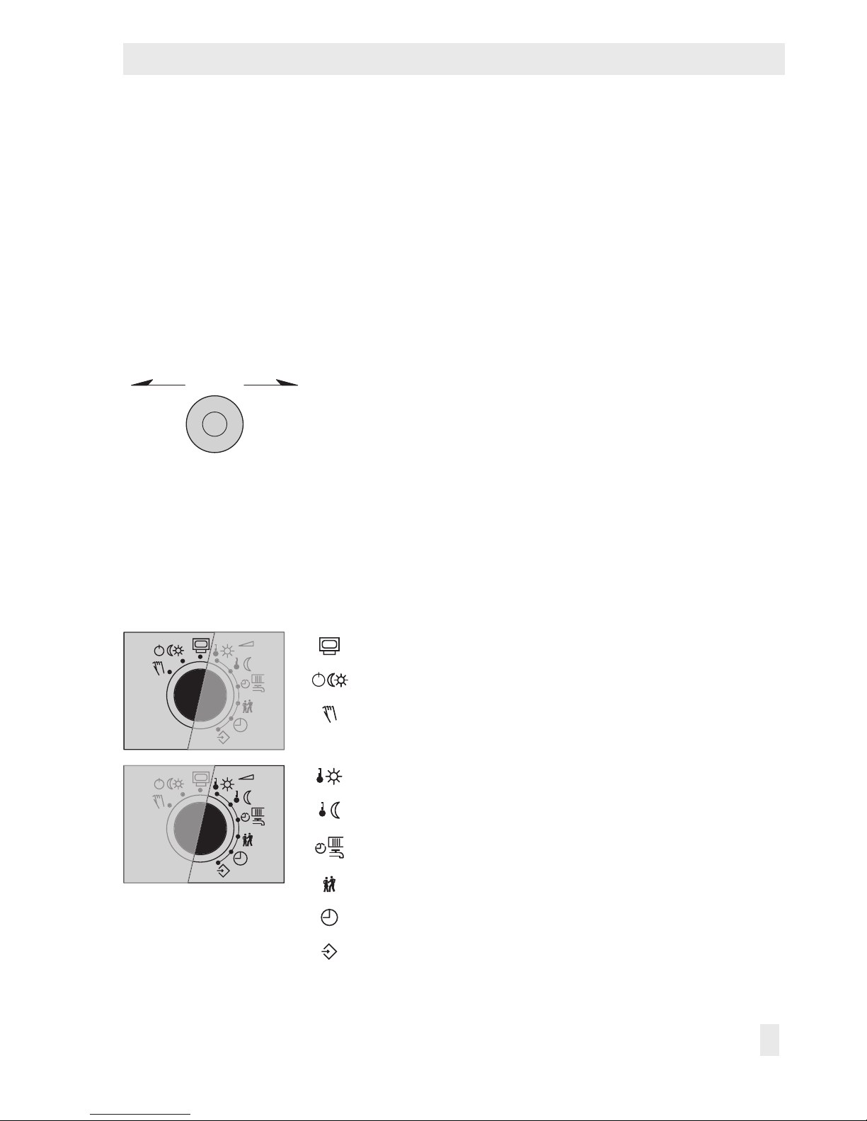
2.1.2 Rotary switch
The rotary switch is used to set the operating mode and the relevant parameters for each
control circuit.
Operating level
Operating modes
Manual level
Day set point (rated room temperature)
Night set point (reduced room temperature)
Times-of-use for heating/DHW
Special time-of-use
Time/date
Settings
Page 8
8 EB 5573-1 EN
Operation
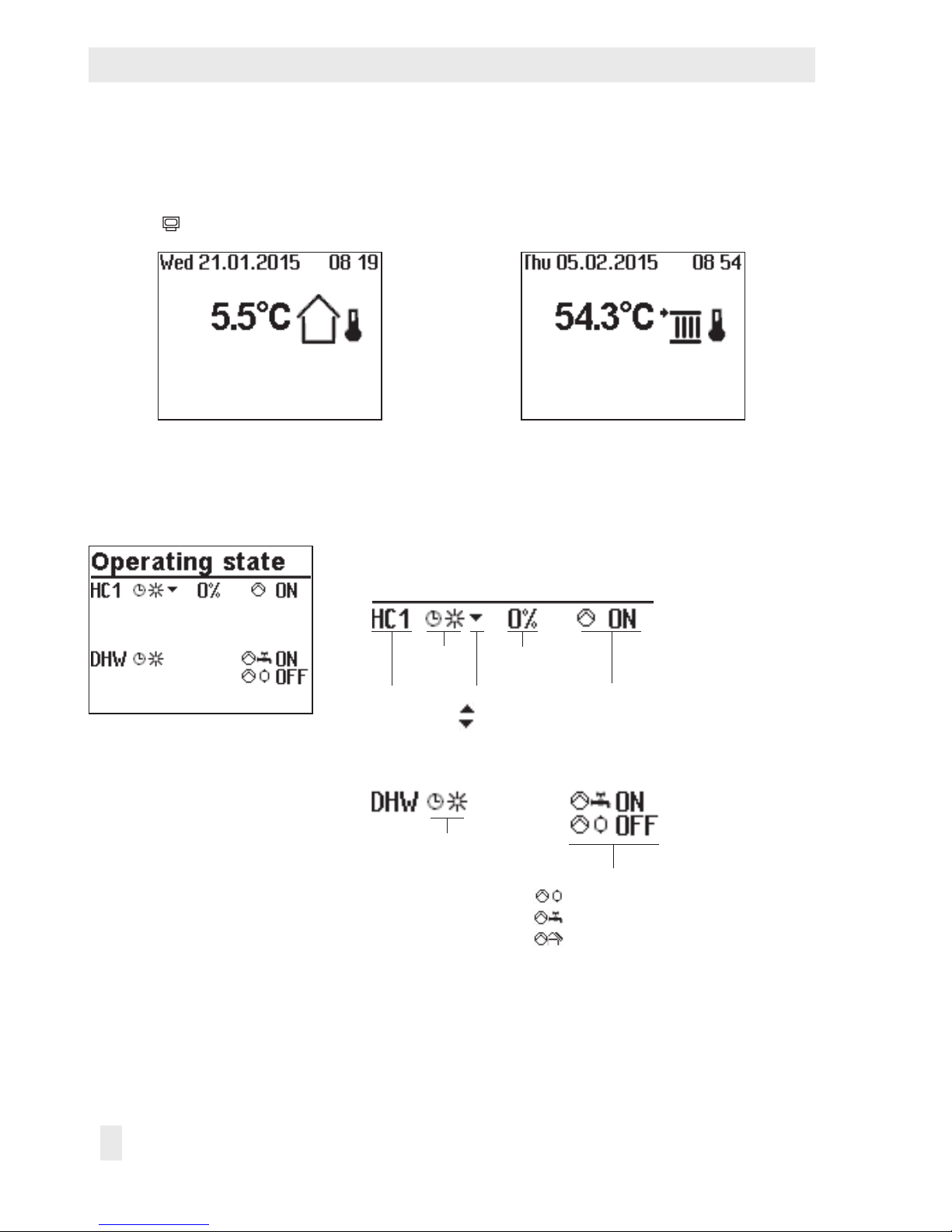
2.2 Reading information
The display indicates the date, time and actual temperature when the rotary switch is posi-
tioned at
(operating level).
Weather-compensated control
current temperature = outdoor temperature
Fixed set point control
current temperature = ow temperature
Further information can be obtained by turning the rotary pushbutton:
q Operating state
The following applies for heating circuits HC1 and HC2:
Heating
circuit
Current
operating
mode
Valve
opens
closes
Actual position-
ing value
Circulation pump
(heating) ON/OFF
The following applies for DHW heating:
Current operating
mode
Pump ON/OFF
Storage tank charging pump
Circulation pump (DHW)
Solar circuit pump
For further details, refer to section2.3.
Page 9
EB 5573-1 EN 9
Operation
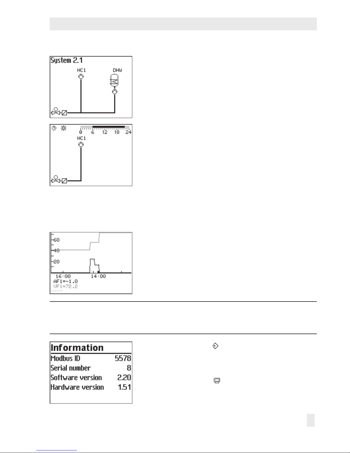
q Selected system code number
For further details, refer to section3.1.
¼ Important measured values of the entire system, e.g. out-
door temperature, ow temperature and return ow temperature, are displayed.
q Times-of-use (depending on system code number)
– Heating circuit HC1
– Heating circuit HC2
– DHW heating
The day mode times is highlighted in black on the time
chart.
Night mode and deactivation times are highlighted in
gray on the time chart.
For further details, refer to section2.5.
¼ Measured values, set points and limits of the system sec-
tion shown are displayed.
q Trend-Viewer
The standard graph shows the data measured at the out-
door sensor AF1 and ow sensor VF1 plotted over time.
For further details, refer to section2.2.1.
Note:
Details on the controller version (device identication, serial number, software and
hardware versions) are displayed in the extended operating level.
Turn the rotary switch to (settings).
q Enter key number 1999.
¼ Conrm key number.
Turn the rotary switch to
(operating level).
q Select 'Information'.
Page 10
10 EB 5573-1 EN
Operation
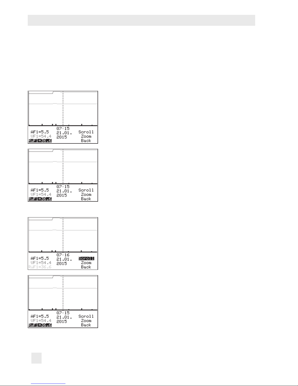
2.2.1 Adapting the Trend-Viewer
The standard graph shows the data measured at the outdoor sensor AF1 and ow sensor
VF1 plotted over time.
¼ Open the Trend-Viewer.
Adding measuring data
q Select – – – – on the display.
¼ Activate editing mode for sensor selection.
q Select sensor.
¼ Conrm selected sensor.
Deleting measured data:
q Select the sensor whose measured data are no longer to
be displayed.
¼ Activate editing mode for sensor.
q Select – – – – on the display.
¼ Conrm deletion.
Shifting the time line:
q Select 'Scroll'.
¼ Activate editing mode for scroll function.
q Shift the time line.
¼ Conrm time display.
Page 11
EB 5573-1 EN 11
Operation
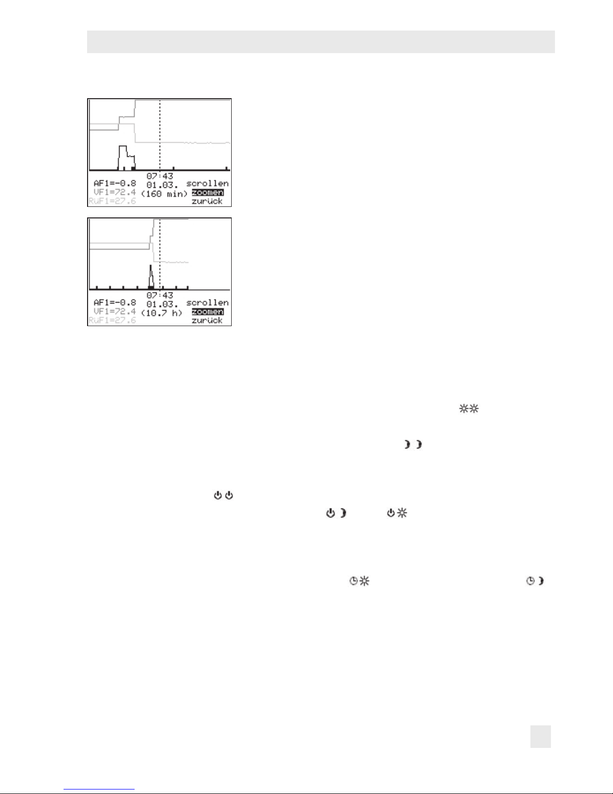
Zooming in/out
q Select 'Zoom'.
¼ Open zoom function.
q Zoom in or out.
¼ Conrm display.
Closing the Trend-Viewer
q Select 'Back'.
¼ Close the Trend-Viewer
2.3 Selecting operating modes
Day mode (rated operation): regardless of the programmed times-of-use and summer mode,
the set points relevant for rated operation are used by the controller. Icon:
Night mode (reduced operation): regardless of the programmed times-of-use, the set points
relevant for reduced operation are used by the controller. Icon:
Control operation deactivated: regardless of the programmed times-of-use, control opera-
tion of the heating circuits and DHW heating remains deactivated. The frost protection is activated, if need be. Icon:
Icons when the frost protection is activated: HC
, DHW
Automatic mode: during the programmed times-of-use, the controller works in day mode.
Outside these times-of-use, the controller is in night mode, unless control operation is deactivated depending on the outdoor temperature. The controller switches automatically between
both operating modes. Icon within the times-of-use:
, icon outside the times-of-use:
Manual mode: valves and pumps can be controlled manually. For further details, refer to
section4.
Page 12
12 EB 5573-1 EN
Operation
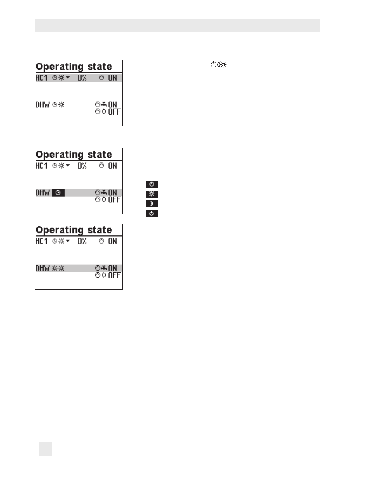
Turn the rotary switch to (operating modes). The operating states of all system control circuits are displayed:
− Heating circuit HC1
− Heating circuit HC2
− DHW heating
Î Only those control circuits are available for selection
which can be controlled by the selected system.
q Select the control circuit.
¼ Activate editing mode for the control circuit. The operat-
ing mode is shown inverted on the display.
q Select the operating mode:
Automatic mode
Day mode
Night mode
System deactivated
¼ Conrm the operating mode.
Page 13
EB 5573-1 EN 13
Operation
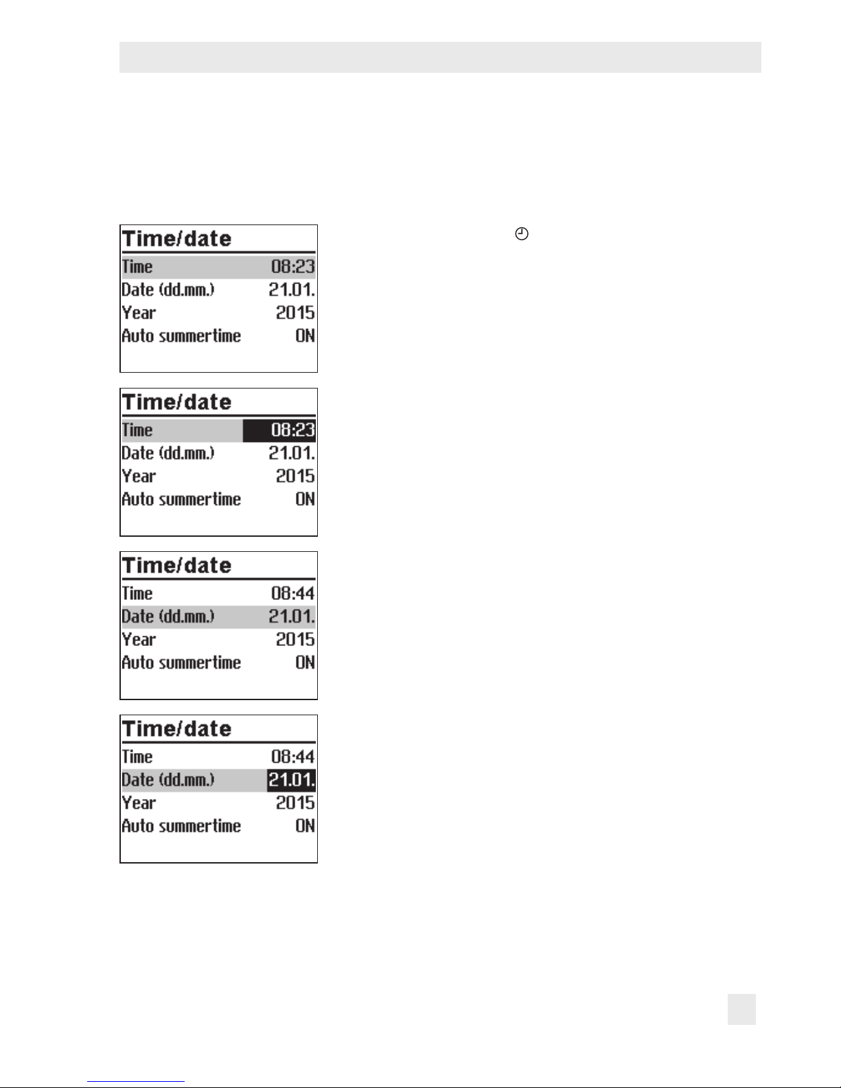
2.4 Setting the time and date
The current time and date need to be set immediately after start-up and after a power failure
lasting more than 24 hours. This is the case when the time blinks on the display.
Turn the rotary switch to (time/date). The current time is
selected (gray background).
¼ Activate editing mode for the time. The time reading is
inverted.
q Change the time.
¼ Conrm the time setting.
q Select 'Date' (dd.mm) [q].
¼ Activate editing mode for the date. The date reading is
inverted.
q Change date (day.month).
¼ Conrm the date setting.
Page 14
14 EB 5573-1 EN
Operation
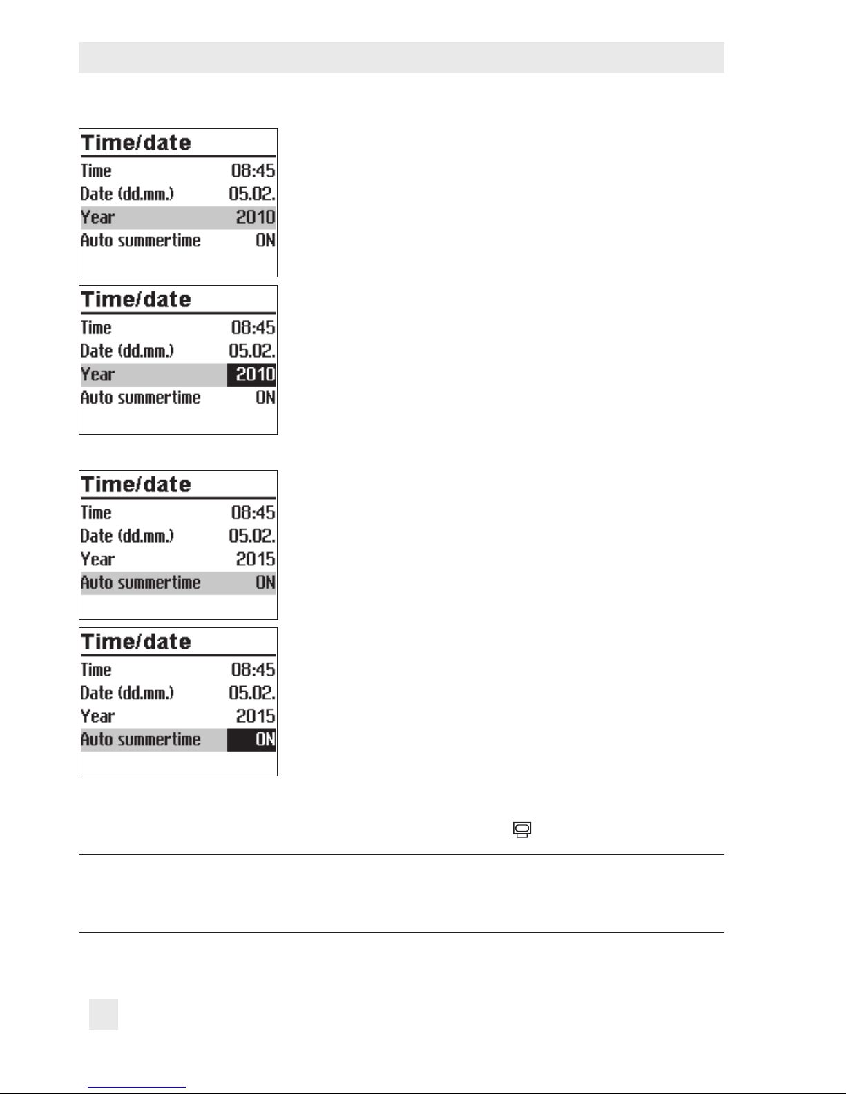
q Select 'Year'.
¼ Activate editing mode for the year. The year reading is
inverted.
q Change the year.
¼ Conrm the year setting.
Deactivate or activate the automatic summer/standard time
switchover as required. Refer to section8.1:
q Select 'Auto summertime'.
¼ Activate the editing mode for automatic summer/stan-
dard time switchover. The current setting is shown inverted on the display:
ON = Summer/standard time switchover active
OFF = Summer/standard time switchover not active
q Deactivate or activate the automatic summer/standard
time switchover.
¼ Conrm deactivation/activation.
Turn the rotary switch back to
(operating level).
Note:
The correct time is guaranteed after a power failure of 24 hours. Normally, the correct time is still retained at least 48 hours after a power failure.
Page 15
EB 5573-1 EN 15
Operation
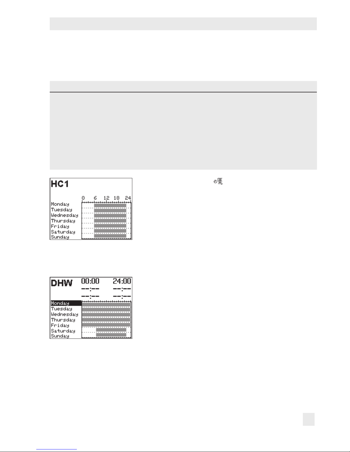
2.5 Setting the times-of-use
Three times-of-use can be set for each day of the week.
Parameters WE Value range
HC1, HC2 DHW, CP
Start rst time-of-use 06:00 00:00 00:00 to 24:00 h; in steps of 15 minutes
Stop rst time-of-use 22:00 24:00 00:00 to 24:00 h; in steps of 15 minutes
Start second time-of-use --:-- --:-- 00:00 to 24:00 h; in steps of 15 minutes
Stop second time-of-use --:-- --:-- 00:00 to 24:00 h; in steps of 15 minutes
Start third time-of-use --:-- --:-- 00:00 to 24:00 h; in steps of 15 minutes
Stop third time-of-use --:-- --:-- 00:00 to 24:00 h; in steps of 15 minutes
Turn the rotary switch to (times-of-use). The rst control
circuit is displayed together with its programmed times-of-
use.
q Program the times-of-use of another control circuit, if re-
quired:
– Heating circuit HC2
– DHW heating
– Circulation pump (DHW) CP
Î Only those control circuits are available for selection
which can be controlled by the selected system.
¼ Activate editing mode for the control circuit. The times-
of-use for Monday are displayed.
Page 16
16 EB 5573-1 EN
Operation
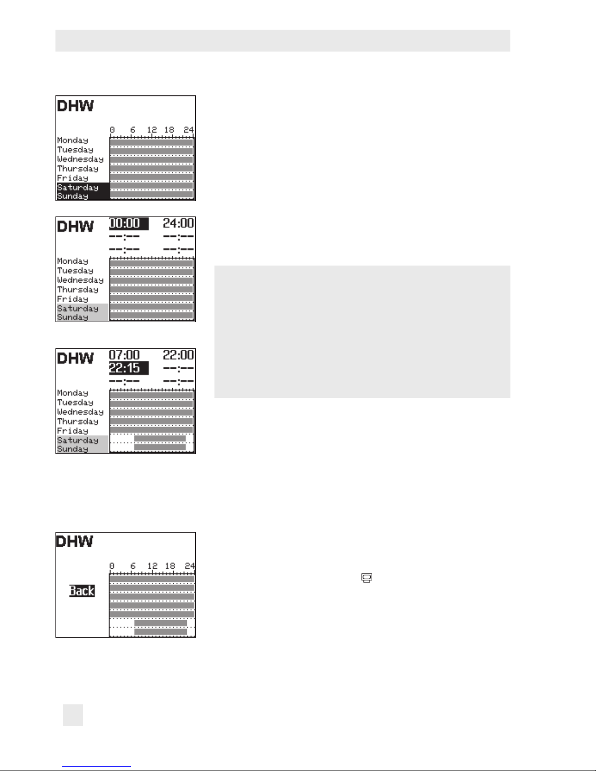
q Select period/day for which the times-of-use are to be
valid. The times-of-use can be programmed for individual days or for a block of days, e.g. Monday to Friday,
Saturday and Sunday or Monday to Sunday. The selected days are shown inverted on the display.
¼ Activate editing mode for the period/day.
The start time of the rst time-of-use period can now be
edited (inverted reading).
q Change start time (in steps of 15 minutes).
¼ Conrm the start time. The stop time of the rst time-of-
use period can now be edited.
q End stop time (in steps of 15 minutes).
¼ Conrm the stop time. The start time of the second time-
of-use period can now be edited.
To set the second and third times-of-use periods, repeat
steps with gray background. If no further times-of-use are to
be programmed for the selected time period/day, exit the
menu by conrming the indicated start time twice (2x Û).
Proceed in the same manner to program further periods/
days.
After setting all times-of-use:
q Select 'Back'.
¼ Exit the times-of-use setting.
Turn the rotary switch back to
(operating level).
Page 17
EB 5573-1 EN 17
Operation
2.6 Setting special times-of-use
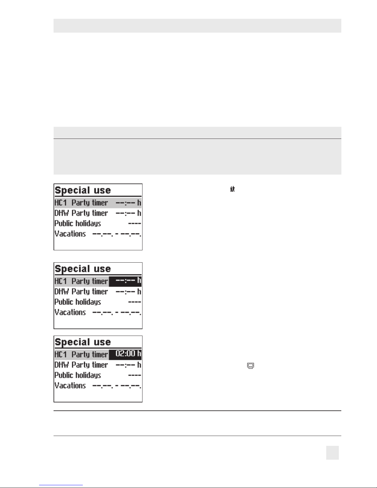
2.6.1 Party timer
Rated operating in the corresponding control circuit (HC1, HC2 or DHW) is started or continued for the time period set in the party timer. When the party timer has elapsed, the party
timer returns to --:--.
Parameters WE Value range
HC1 party timer --:-- h 0 to 48h; in steps of 15 minutes
HC2 party timer --:-- h 0 to 48h; in steps of 15 minutes
DHW party timer --:-- h 0 to 48h; in steps of 15 minutes
Turn the rotary switch to (special times-of-use). The party
timer for the rst control circuit is now selected.
q Set party timer of another control circuit, if required:
– Heating circuit HC2
– DHW heating
Î Only those control circuits are available for selection
which can be controlled by the selected system.
¼ Activate editing mode for the party timer. The party tim-
er is now in the editing mode (inverted display).
q Extend day operation as required (in steps of 15 min-
utes).
¼ Conrm setting.
After setting the party timer:
Turn the rotary switch back to
(operating level).
Note:
Party timer runs down in steps of 15 minutes.
Page 18
18 EB 5573-1 EN
Operation
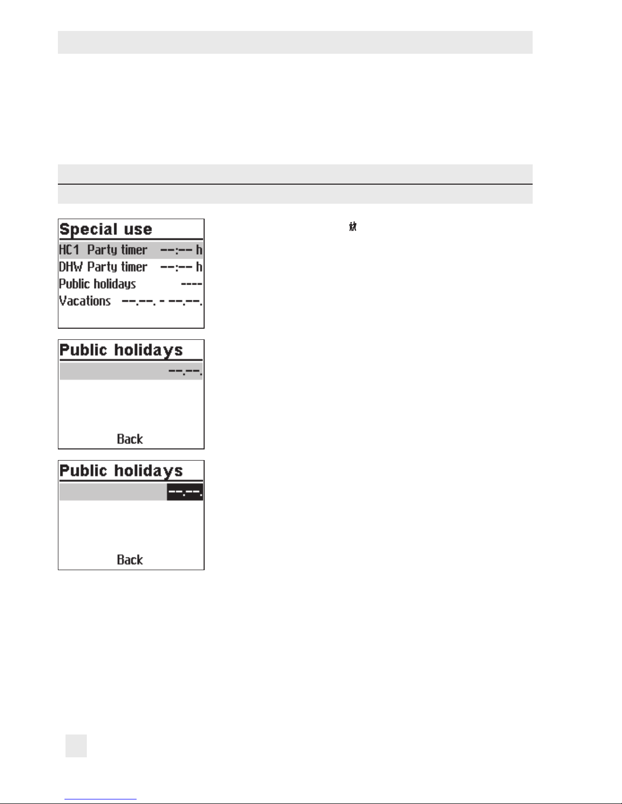
2.6.2 Public holidays
On public holidays, the times-of-use specied for Sunday apply.
A maximum of 20 public holidays may be entered.
Parameters WE Value range
Public holidays --:-- 01.01 to 31.12
Turn the rotary switch to (special times-of-use). The party
timer for the rst control circuit is now selected.
q Select 'Public holidays'.
¼ Start the public holiday setting. The rst public holiday
setting is now selected. --:-- is displayed if no public holidays (default setting) have been programmed.
q Select --:--, if applicable.
¼ Activate editing mode for public holidays.
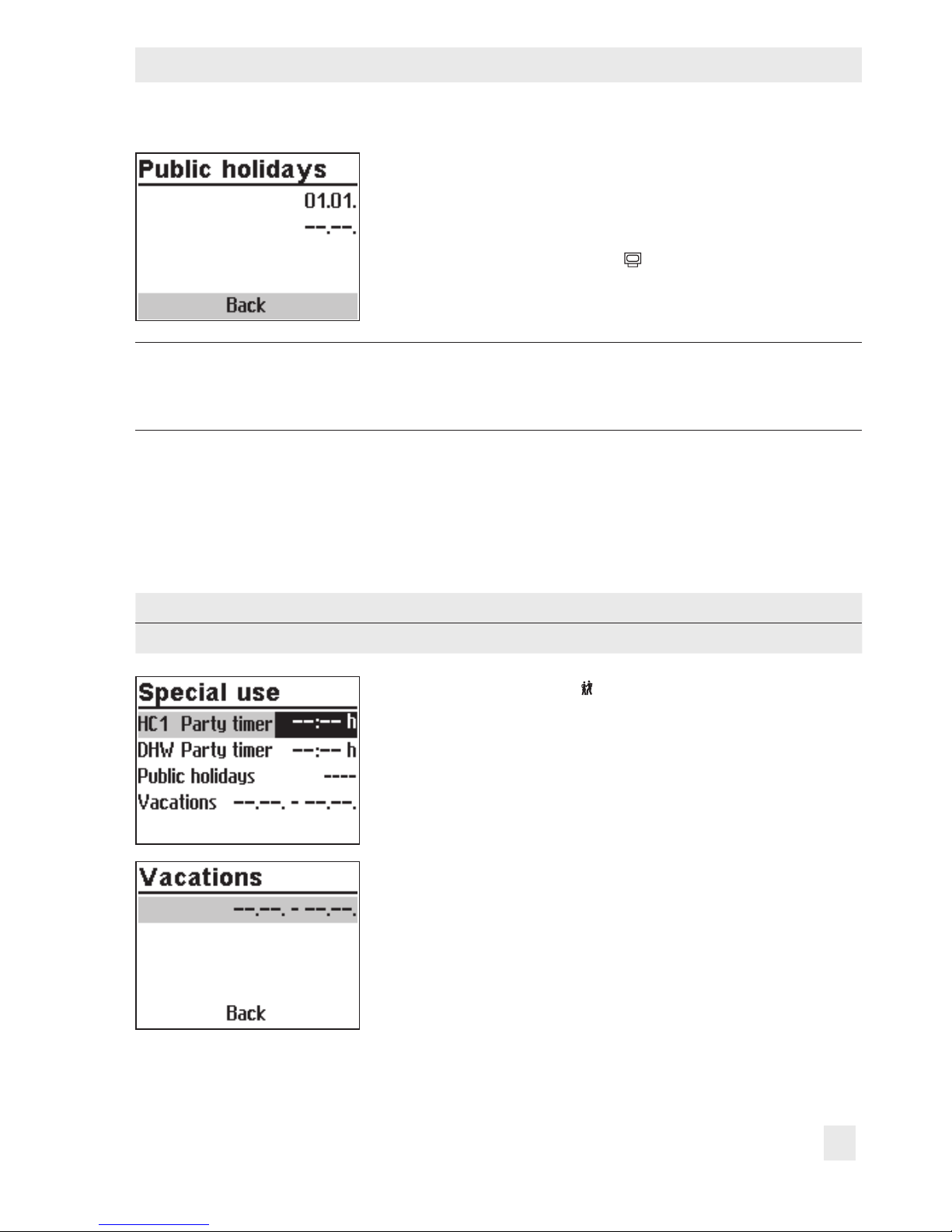
q Set the date of the public holiday.
¼ Conrm the date.
Proceed in the same manner to program further public holi-
days.
Deleting a public holiday:
q Select the holiday you wish to delete.
¼ Conrm the date.
q Select --:--.
¼ Conrm setting.
The public holiday is deleted.
Page 19
EB 5573-1 EN 19
Operation
After programming all public holidays:
q Select 'Back'.
¼ Exit the public holiday setting.
Turn the rotary switch back to
(operating level).
Note:
Public holidays that are not assigned to a specic date should be deleted by the end
of the year so that they are not carried on into the following year.
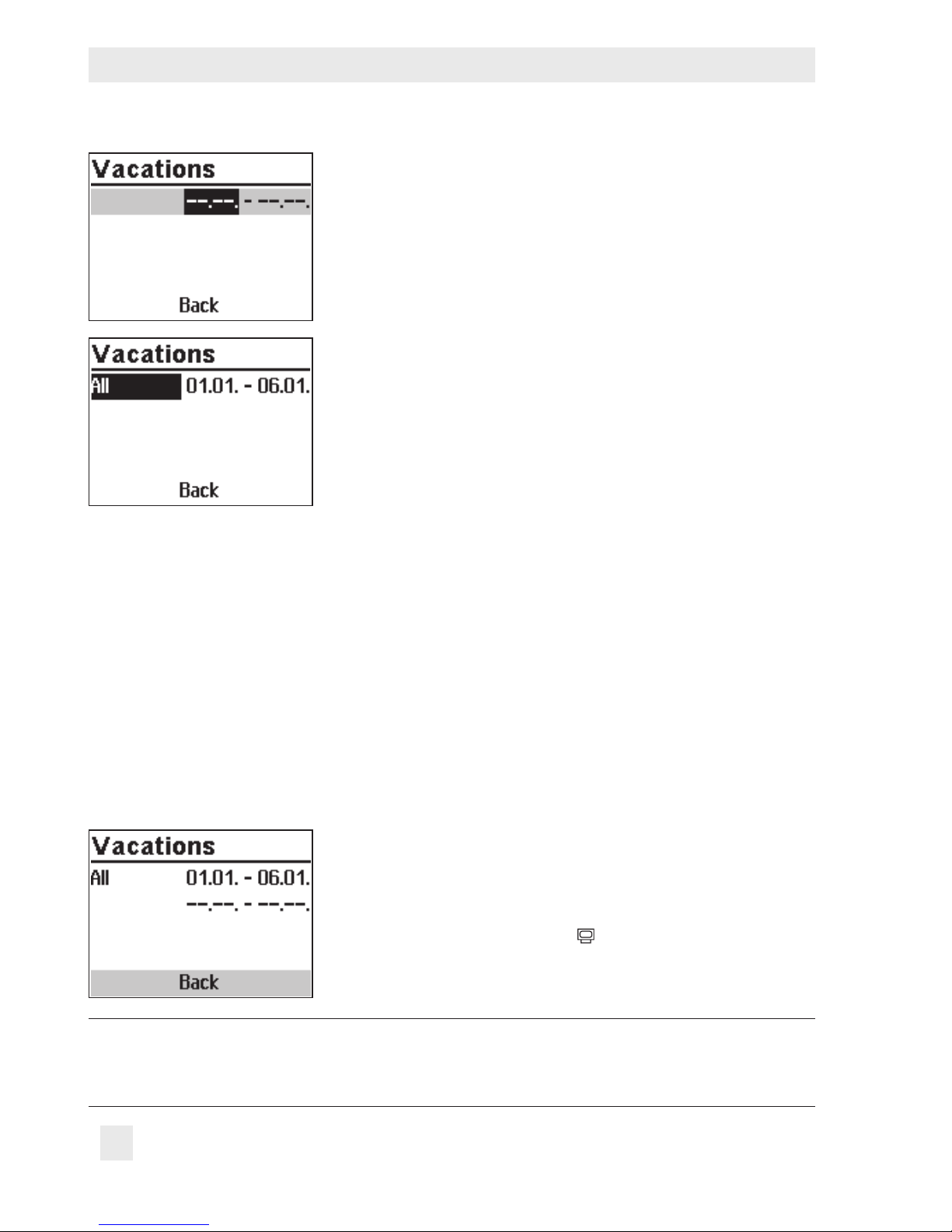
2.6.3 Vacations
The system runs constantly in reduced mode during vacation periods. A maximum of ten vacation periods can be entered. Each vacation period can be separately assigned to the heating circuits HC1, HC2 and DHW circuit or to all control circuits.
Parameters WE Value range
Vacation period --.-- - --.-- 01.01 to 31.12
Turn the rotary switch to (special times-of-use). The party
timer for the rst control circuit is now selected.
q Select 'Vacations'.
¼ Start the vacations setting. The rst vacations setting is
now selected. --.-- - --.--.is displayed if no vacations (default setting) have been programmed.
q Select --.-- - --.--, if applicable.
Page 20
20 EB 5573-1 EN
Operation
q Activate editing mode for vacations.
The start date can now be edited (inverted reading).
q Set the start date.
q Conrm the start date.
The end date can now be edited.
q Set the end date.
q Conrm the year setting. 'All' is selected. The vacation
period then applies to all control circuits.
q If the vacation period is to be only valid for one control
circuit, select the required control circuit:
– Heating circuit HC1
– Heating circuit HC2
– DHW heating
Î Only those control circuits are available for selection
which can be controlled by the selected system.
¼ Conrm the control circuit.
Proceed in the same manner to program further vacations.
Deleting vacation periods:
q Select the start date of the period you wish to delete.
¼ Conrm vacation period.
q Select --.-- - --.--.
¼ Conrm setting.
The vacation period is deleted.
After programming all vacation periods:
q Select 'Back'.
¼ Exit the vacations setting.
Turn the rotary switch back to
(operating level).
Note:
Vacations should be deleted by the end of the year so that they are not carried on into the following year.
Page 21
EB 5573-1 EN 21
Operation
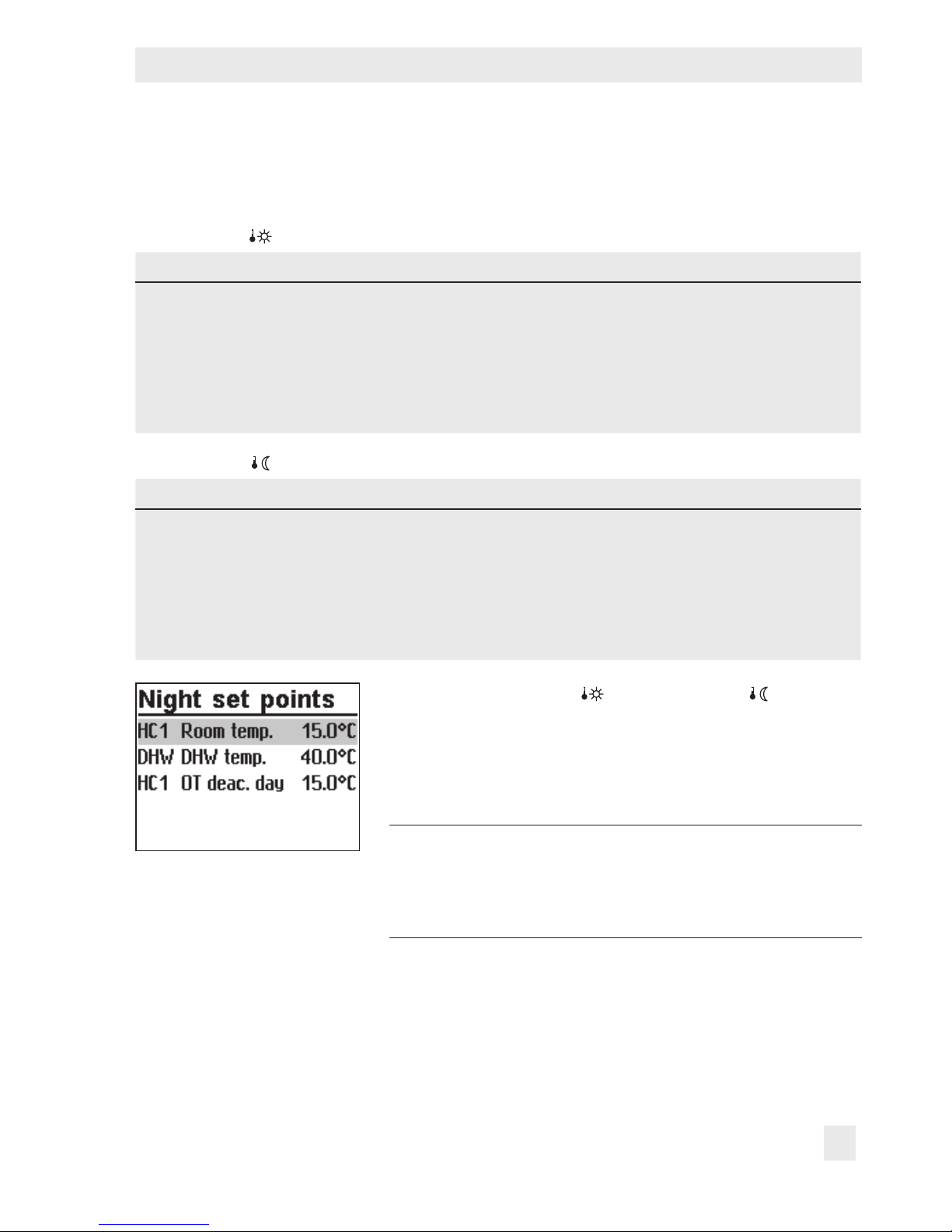
2.7 Entering day and night set points
The desired room temperature for the day and night set points can be programmed.
Switch position
Parameters WE Value range
HC1 room temperature 20.0°C 0.0 to 40.0°C
HC2 room temperature 20.0°C 0.0 to 40.0°C
DHW temperature 55.0°C Min. to max. DHW temperature
HC1 OT deactivation value 22.0°C 0.0 to 50.0°C
HC2 OT deactivation value 22.0°C 0.0 to 50.0°C
Switch position
Parameters WE Value range
HC1 room temperature 15.0°C 0.0 to 40.0°C
HC2 room temperature 15.0°C 0.0 to 40.0°C
DHW temperature 40.0°C Min. to max. DHW temperature
HC1 OT deactivation value 15.0°C 0.0 to 50.0°C
HC2 OT deactivation value 15.0°C 0.0 to 50.0°C
Turn the rotary switch to (day set point) or (night set
point).
The day or night set points are listed on the display.
Î Only those day and night set points are available for se-
lection which can be controlled by the selected system.
Note:
The deactivation values are located in a separate
menu (deactivation values) for systems with three
control circuits.
q Select the set point.
Page 22

22 EB 5573-1 EN
Operation
¼ Activate editing mode for set point.
q Adjust the set point.
¼ Conrm setting.
Proceed in the same manner to adjust further set points.
After adjusting all the set points:
Turn the rotary switch back to
(operating level).
Page 23
EB 5573-1 EN 23
Start-up
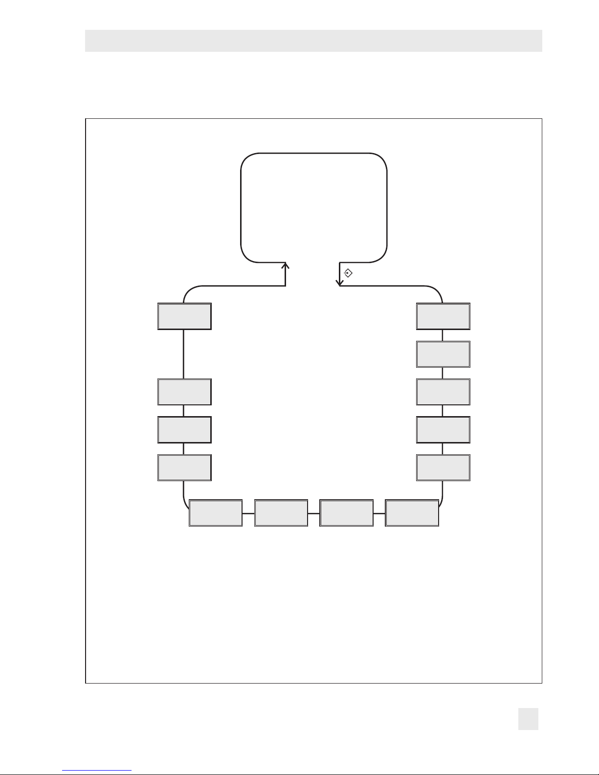
3 Start-up
q
Operating level
q
Conguration and
parameter level
Perform start-up. Refer to section3.
Back
System
CO6
CO5
CO4 CO2 CO1 PA6
PA1
PA2
PA4
Display
contrast
Display
language
& key number
¼
PA1/CO1:
PA2/CO2:
PA4/CO4:
CO5:
PA6/CO6:
Anl:
RK1 (heating circuit 1)
RK2 (heating circuit 2)
DHW circuit
System-wide
Modbus communication
System code number
Fig. 1: Level structure of TROVIS 5573
Page 24

24 EB 5573-1 EN
Operation
The modications of the controller conguration and parameter settings described in this section can only be performed after the valid key number has been entered.
The key number that is valid on the rst start-up can be found on page163. To avoid unauthorized use of the service key number, remove the page or make the key number unreadable. In addition, it is possible to enter a new, customized key number (refer to section8.16).
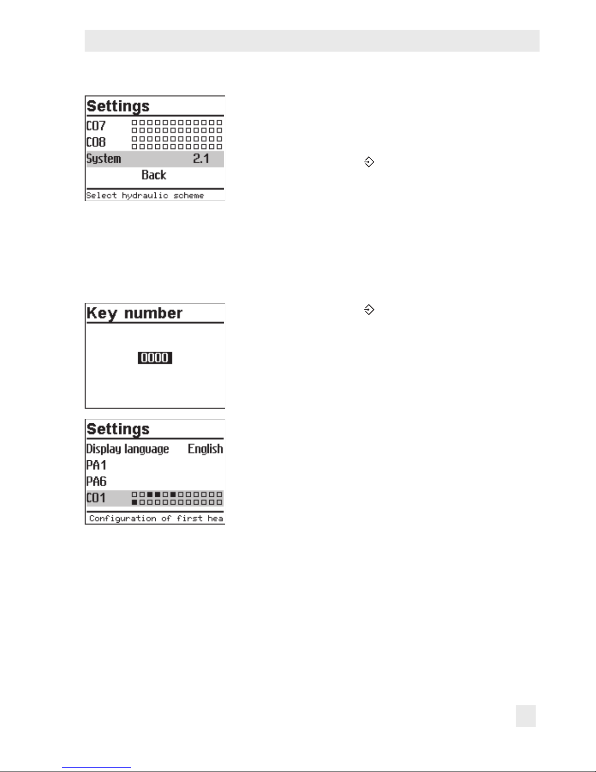
3.1 Setting the system code number
31 different hydraulic schematics are available. Each system conguration is represented by
a system code number. The different schematics are dealt with in section5. Available controller functions are described in sections6, 7 and 8.
Changing the system code number resets previously adjusted function blocks to their default
settings (WE). Function block parameters and parameter level settings remain unchanged.
The system code number is set in the conguration and parameter level.
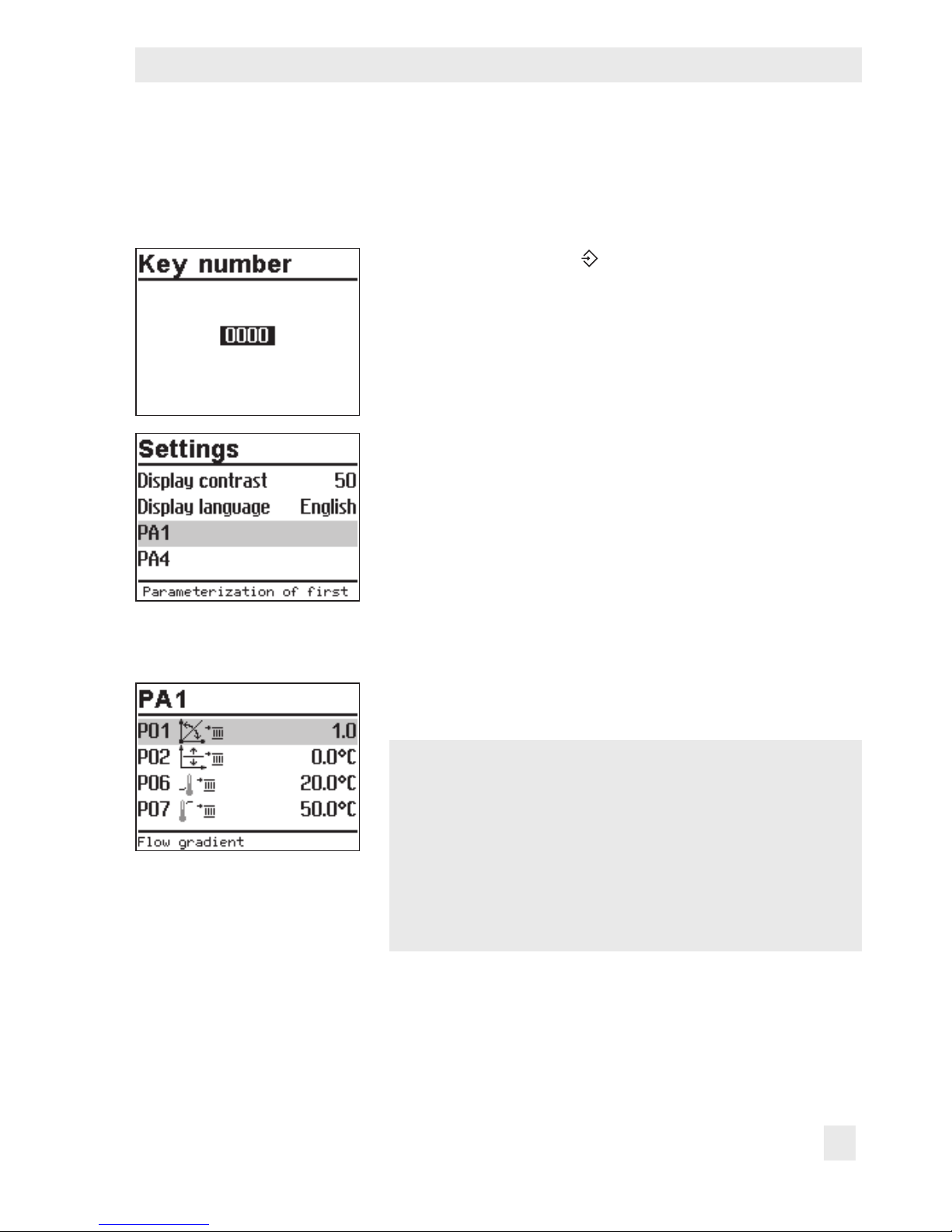
Turn the rotary switch to (settings).
q Enter the currently valid key number.
¼ Conrm key number.
q Select 'System'.
¼ Open 'System'.
q Select the required system.
Page 25
EB 5573-1 EN 25
Operation
¼ Conrm the system selected.
q Select 'Back'.
¼ Exit menu.
Turn the rotary switch to
(settings).
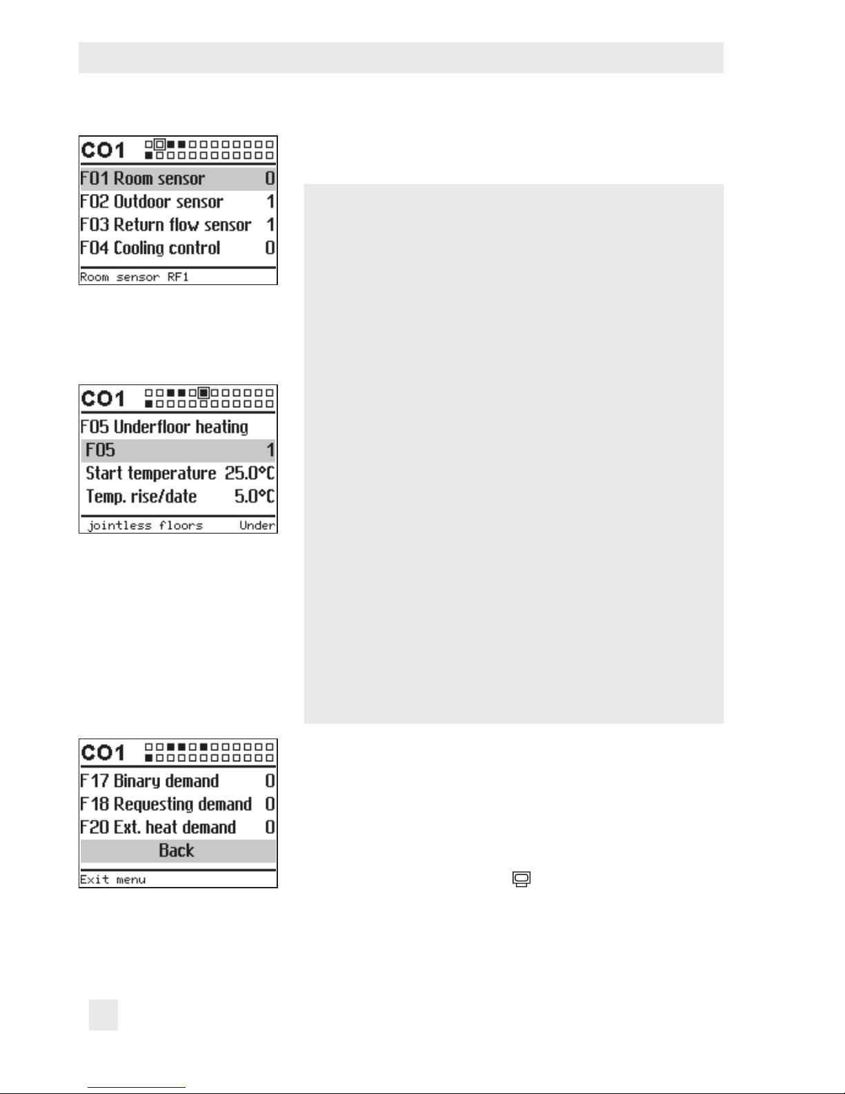
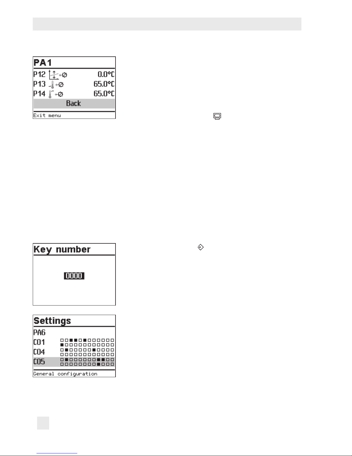
3.2 Activating and deactivating functions
A function is activated or deactivated in the associated function block. For more details on
function blocks, refer to section13.1.
Turn the rotary switch to (settings).
q Enter the currently valid key number.
¼ Conrm key number.
q Select the required conguration level:
– CO1: Heating circuit HC1
– CO2: Heating circuit HC2
– CO3: Not applicable
– CO4: DHW heating
– CO5: System-wide functions
– CO6: Modbus communication
Active function blocks are indicated by the black
squares.
Î Only those conguration levels are available for selec-
tion which can be controlled by the selected system.
Page 26
26 EB 5573-1 EN
Operation
¼ Open conguration level.
The rst function block is selected (marked gray).
q Select function.
Functions without function block parameters:
¼ Activate editing mode for the function.
The currently active conguration '0' or '1' is shown in-
verted on the display.
q Activate function (1) or deactivate function (0).
¼ Conrm conguration.
Functions with function block parameters:
¼ Open function.
q Select conguration.
¼ Activate editing mode for conguration.
The currently active conguration '0' or '1' is shown in-
verted on the display.
q Activate function (1) or deactivate function (0).
¼ Conrm conguration.
q Select function block parameter.
¼ Activate editing mode for function block parameter.
The current setting is shown inverted on the display.
q Set function block parameter.
Proceed in the same manner to set further function blocks.
Exit conguration level:
q Select 'Back'.
q Exit conguration level.
To adjust further function blocks in other conguration levels,
repeat steps with gray background.
Turn the rotary switch back to
(operating level).
Page 27
EB 5573-1 EN 27
Operation
3.3 Changing parameters
Depending on the system code number selected and the activated functions, not all parameters listed in section13.2 might be available.
Turn the rotary switch to (settings).
q Enter the currently valid key number.
¼ Conrm key number.
q Select the required parameter level:
– PA1: Heating circuit HC1
– PA2: Heating circuit HC2
– PA3: Not applicable
– PA4: DHW heating
– PA5: Not applicable
– PA6: Modbus communication
Î Only those parameter levels are available for selection
which can be controlled by the selected system.
¼ Open parameter level.
The rst parameter is selected (marked gray).
q Select parameter.
¼ Activate editing mode for the parameter.
The current setting is shown inverted on the display.
q Set the parameter.
¼ Conrm setting.
¼ Proceed in the same manner to change further parame-
ters.
Page 28
28 EB 5573-1 EN
Operation
Exit parameter level.
q Select 'Back'.
q Exit conguration level.
To adjust further function blocks in other conguration levels,
repeat steps with gray background.
Turn the rotary switch back to
(operating level).
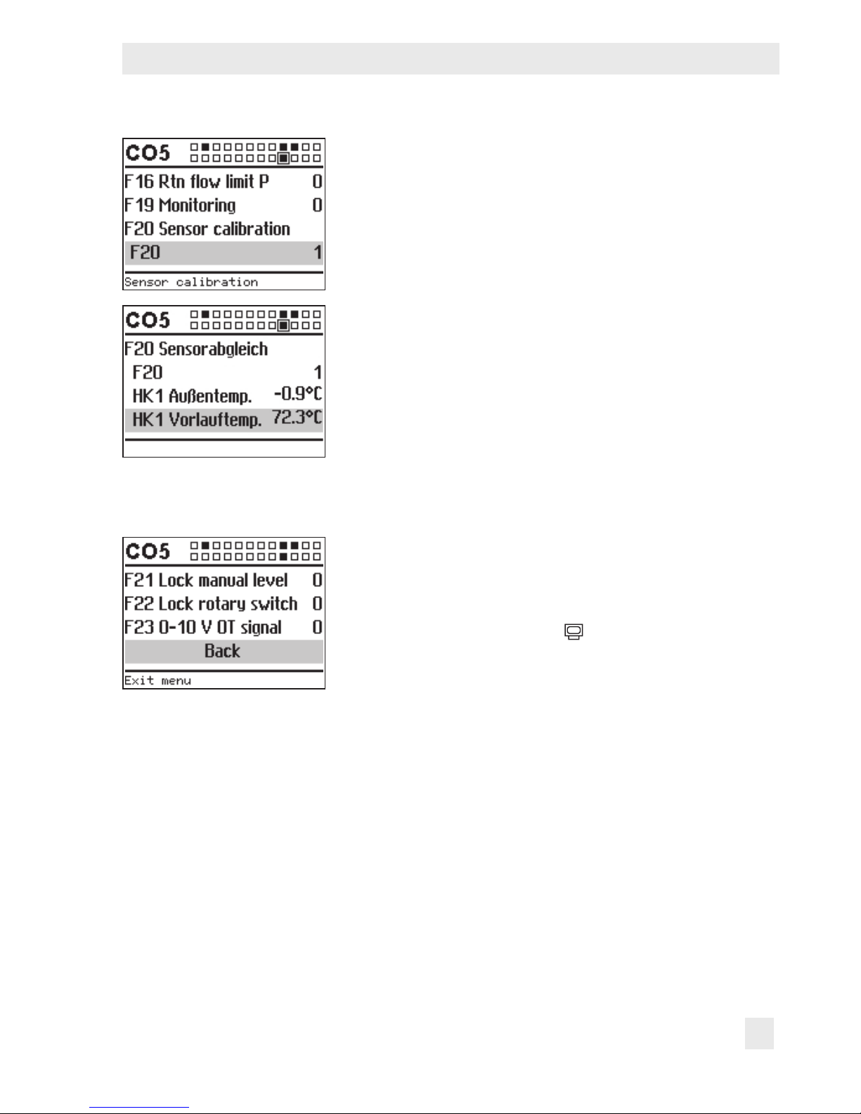
3.4 Calibrating sensors
The controller is designed for connection of Pt1000 sensors. The Pt 1000 resistance values
are listed on page150.
If the temperature values displayed at the controller differ from the actual temperatures, the
measured values of all connected sensors can be recalibrated. To calibrate a sensor, the currently displayed sensor value must be changed such that it matches the temperature (reference temperature) measured directly at the point of measurement. Sensor calibration is activated in CO5 in F20 function block.
An incorrect sensor calibration can be deleted by setting F20 - 0.
Turn the rotary switch to (settings).
q Enter the currently valid key number.
¼ Conrm key number.
¼ Select CO5 conguration level.
¼ Open CO5 conguration level.
¼ Select F20 function block.
¼ Activate editing mode for F20 function block.
Page 29
EB 5573-1 EN 29
Operation
q Select F20 conguration.
¼ Activate editing mode for conguration.
The currently active conguration '0' or '1' is shown in-
verted on the display.
q Activate function block ('1').
¼ Conrm activation.
¼ Select the temperature that you want to calibrate.
¼ Open calibration.
The temperature is shown inverted on the display.
¼ Correct measured value.
Read the actual temperature directly from the thermometer at the point of measurement and enter this value as
the reference temperature.
¼ Conrm corrected measured value.
¼ Proceed in the same manner to calibrate further sensors.
Exit conguration level:
q Select 'Back'.
q Exit conguration level.
Turn the rotary switch back to
(operating level).
Page 30
30 EB 5573-1 EN
Operation
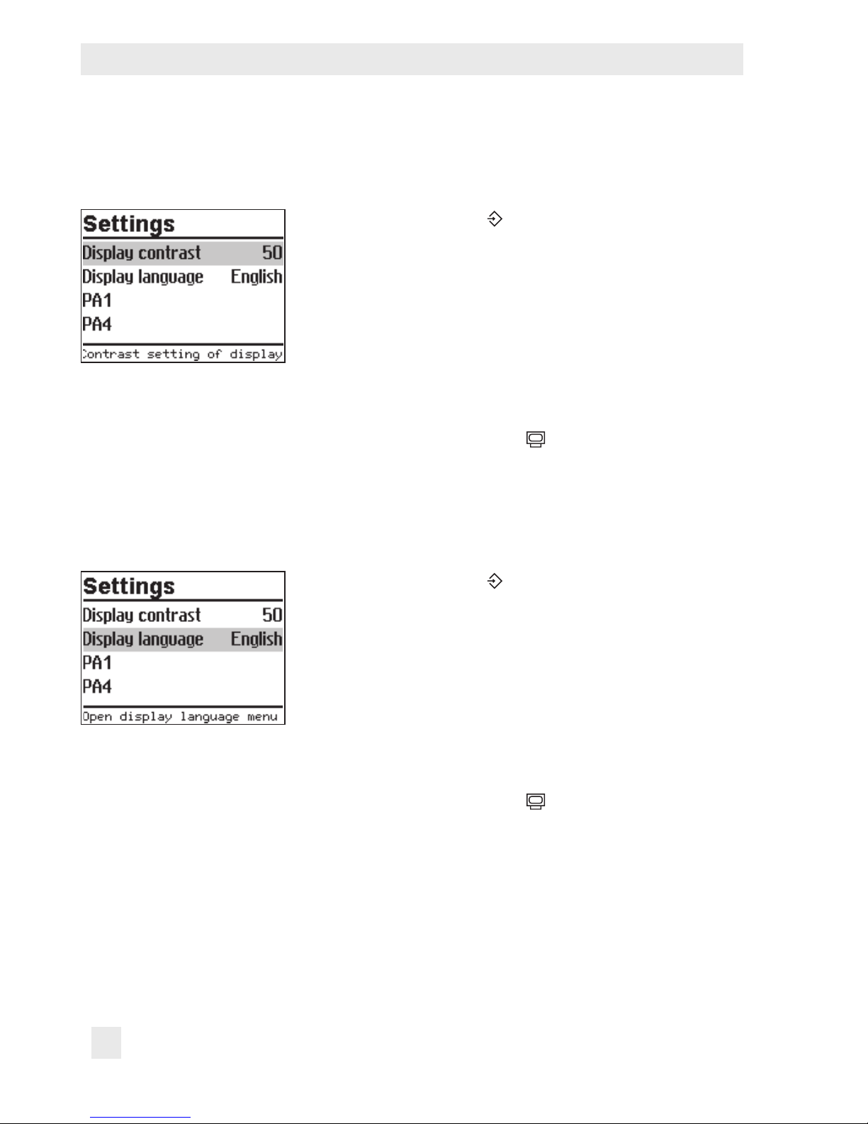
3.5 Altering the display contrast
You can alter the contrast of the display.
Turn the rotary switch to (settings).
q Enter the currently valid key number.
¼ Conrm key number.
q Select 'Display contrast'.
¼ Activate editing mode for the display contrast.
The current setting is shown inverted on the display.
q Set the display contrast
¼ Conrm setting.
Turn the rotary switch back to
(operating level).
3.6 Changing the display language
The default display language is German. The setting can be changed to English.
Turn the rotary switch to (settings).
q Enter the currently valid key number.
¼ Conrm key number.
q Select 'Display language'.
¼ Activate editing mode for the language setting.
The currently valid language is selected.
q Change language setting.
¼ Conrm setting.
Turn the rotary switch back to
(operating level).
Page 31

EB 5573-1 EN 31
Operation
3.7 Loading default setting
All parameters set over the rotary switch as well as parameters in the PA1 and PA2 parameter levels can be reset to their default settings (WE), except for the maximum ow temperature and the return ow temperature limits in PA1 and PA2.
Turn the rotary switch to (settings).
q Enter key number 1991.
¼ Conrm key number.
The settings are reset when the following icon appears
on the controller display:
Page 32

32 EB 5573-1 EN
Manual mode
4 Manual mode
Switch to manual mode to congure all outputs (refer to section12).
NOTICE
The frost protection does not function when the controller is in manual mode.
Changing positioning value/switching state manually:
Turn the rotary switch to (manual mode).
The outputs of the congured system are listed on the
display.
q Select the output
Positioning value
Circulation pump (heating)
Storage tank charging pump
Circulation pump (DHW)
Solar circuit pump
q Activate editing mode for the output.
q Change the positioning value/switching state.
q Conrm the positioning value/switching state.
The modied values remain active as long as the control-
ler is in manual mode.
Turn the rotary switch to
(operating level). The manual
mode is deactivated.
Note:
The outputs of the controller are not affected by merely turning the rotary switch to
(manual mode). The outputs are only changed by entering or changing the position-
ing values or switching states.
Page 33

EB 5573-1 EN 33
Systems
5 Systems
31 different hydraulic schematics are available.
Boiler systems:
Single-stage boiler systems can be congured from any system whose heating circuits and
DHW circuit include just one heat exchanger. These systems are Anl 1.0-1, 1.5-1, 1.6-1,
1.6-2, 1.9-1, 1.9-2, 2.x, 3.0, 3.5, 4.0 and 4.1.
The boiler can be controlled by an on/off output (CO1 > F12 - 0).
RK1/Y1 RüF1 VF1 UP1 RF1
BE
BA
AE
RK
RK1_2 Pkt VF1 UP1 RF1
BE
BA
AE
RK
Single-stage boiler
Fig. 2: Conguration of a boiler system
Page 34

34 EB 5573-1 EN
Systems
System Anl 1.0-1
BE
BA
AE
RK
AF1
RüF1 VF1
UP1RK1/Y1
RF1
Default settings
CO1 > F01 - 0 (without RF1)
CO1 > F02 - 1 (with AF1)
CO1 > F03 - 1 (with RüF1)
CO5 > F07 - 0 (without error indication at terminal 29)
Page 35

EB 5573-1 EN 35
Systems
System Anl 1.0-2
BE
BA
AE
RK
AF1
RF1
RüF1
VF1
UP1
RK1/Y1
Default settings
CO1 > F01 - 0 (without RF1)
CO1 > F02 - 1 (with AF1)
CO1 > F03 - 1 (with RüF1)
CO5 > F07 - 0 (without error indication at terminal 29)
Page 36

36 EB 5573-1 EN
Systems
System Anl 1.1-1
AF1
BE
BA
AE
RK
WW
KW
VF4 ZP SF1RF1UP1 RK1/Y1
VF1
RüF1
SLP (RK2)
Default settings
CO1 > F01 - 0 (without RF1)
CO1 > F02 - 1 (with AF1)
CO1 > F03 - 1 (with RüF1)
CO4 > F01 - 1 (with SF1)
CO4 > F02 - 0 (without SF2)
CO4 > F05 - 0 (without VF4)
CO5 > F07 - 0 (without error indication at terminal 29)
Page 37

EB 5573-1 EN 37
Systems
System Anl 1.1-2
UP1 SLP
AF1
RK1/Y1 VF1 RüF1 RF1
BE
BA
AE
RK
WW
KW
SF1ZPVF4
Default settings
CO1 > F01 - 0 (without RF1)
CO1 > F02 - 1 (with AF1)
CO1 > F03 - 1 (with RüF1)
CO4 > F01 - 1 (with SF1)
CO4 > F02 - 0 (without SF2)
CO4 > F05 - 0 (without VF4)
CO5 > F07 - 0 (without error indication at terminal 29)
Page 38

38 EB 5573-1 EN
Systems
System Anl 1.2
BE
BA
AE
RK
WW
KW
UP1
RK1/Y1
VF1
RüF1
RF1
TLP
AF1
VF4
SLP
SF2ZPSF1
Default settings
CO1 > F01 - 0 (without RF1)
CO1 > F02 - 1 (with AF1)
CO1 > F03 - 0 (without RüF1)
CO4 > F01 - 1 (with SF1)
CO4 > F02 - 1 (with SF2)
CO4 > F05 - 0 (without VF4)
CO5 > F07 - 0 (without error indication at terminal 29)
Page 39

EB 5573-1 EN 39
Systems
System Anl 1.3-1
BE
BA
AE
RK
AF1
WW
KW
CP
VF3
SF2
ZP
SF1
SLP (RK2)
RK1/Y1
VF1
UP1
RüF1
RF1
Default settings
CO1 > F01 - 0 (without RF1)
CO1 > F02 - 1 (with AF1)
CO1 > F03 - 1 (with RüF1)
CO4 > F01 - 1 (with SF1)
CO5 > F07 - 0 (without error indication at terminal 29)
Page 40

40 EB 5573-1 EN
Systems
System Anl 1.3-2
BE
BA
AE
RK
UP1
RK1/Y1
VF1
RüF1
RF1
AF1
WW
KW
CP
VF3 SF2
ZP
SF1
SLP
Default settings
CO1 > F01 - 0 (without RF1)
CO1 > F02 - 1 (with AF1)
CO1 > F03 - 1 (with RüF1)
CO4 > F01 - 1 (with SF1)
CO5 > F07 - 0 (without error indication at terminal 29)
Page 41

EB 5573-1 EN 41
Systems
System Anl 1.5-1
BE
BA
AE
RK
WW
KW
ZP
SLP
RüF1
VF1 SF1
RK1/Y1
Default settings
CO1 > F03 - 1 (with RüF1)
CO4 > F01 - 1 (with SF1)
CO4 > F02 - 0 (without SF2)
CO5 > F07 - 0 (without error indication at terminal 29)
Page 42

42 EB 5573-1 EN
Systems
System Anl 1.5-2
BE
BA
AE
RK
WW
KW
ZP
VF1
SF1
SLP
RüF1RK1/Y1
Default settings
CO1 > F03 - 1 (with RüF1)
CO4 > F01 - 1 (with SF1)
CO4 > F02 - 0 (without SF2)
CO5 > F07 - 0 (without error indication at terminal 29)
Page 43

EB 5573-1 EN 43
Systems
System Anl 1.6-1
BE
BA
AE
RK
WW
KW
SF2
ZP SLP
VF1 SF1RK1/Y1
RüF1
Default settings
CO1 > F03 - 1 (with RüF1)
CO4 > F01 - 1 (with SF1)
CO4 > F02 - 1 (with SF2)
CO5 > F07 - 0 (without error indication at terminal 29)
Page 44

44 EB 5573-1 EN
Systems
System Anl 1.6-2
BE
BA
AE
RK
WW
KW
SF2
ZP SLP
UP1 VF1
VF4 SF1
RK1/Y1
RüF1
Default settings
CO1 > F03 - 1 (with RüF1)
CO4 > F01 - 1 (with SF1)
CO4 > F02 - 1 (with SF2)
CO4 > F05 - 0 (without VF4)
CO5 > F07 - 0 (without error indication at terminal 29)
Page 45

EB 5573-1 EN 45
Systems
System Anl 1.6-3
BE
BA
AE
RK
WW
KW
SF2
ZP SLP
VF1 SF1
RüF1
RK1/Y1
UP1
Default settings
CO1 > F03 - 1 (with RüF1)
CO4 > F01 - 1 (with SF1)
CO4 > F02 - 1 (with SF2)
CO4 > F05 - 0 (without VF4)
CO5 > F07 - 0 (without error indication at terminal 29)
Page 46

46 EB 5573-1 EN
Systems
System Anl 1.9
BE
BA
AE
RK
RK2
WW
KW
ZP
VF2
SF1RüF2
BE2
Default settings
CO4 > F01 - 0 (without SF1)
CO4 > F03 - 0 (without RüF2)
CO4 > F04 - 0 (without ow rate sensor)
CO5 > F07 - 0 (without error indication at terminal 29)
Page 47

EB 5573-1 EN 47
Systems
System Anl 2.0
BE
BA
AE
RK
WW
KW
AF1
ZP
RüF1
VF1
UP1
SLP (RK2)
SF1
RK1/Y1
RF1
Default settings
CO1 > F01 - 0 (without RF1)
CO1 > F02 - 1 (with AF1)
CO1 > F03 - 1 (with RüF1)
CO4 > F01 - 1 (with SF1)
CO4 > F02 - 0 (without SF2)
CO5 > F07 - 0 (without error indication at terminal 29)
Page 48

48 EB 5573-1 EN
Systems
System Anl 2.1
BE
BA
AE
RK
AF1
RüF1 VF1
UP1RK1/Y1 RF1
SLP
WW
KW
ZP
SF1
Default settings
CO1 > F01 - 0 (without RF1)
CO1 > F02 - 1 (with AF1)
CO1 > F03 - 1 (with RüF1)
CO4 > F01 - 1 (with SF1)
CO4 > F02 - 0 (without SF2)
CO5 > F07 - 0 (without error indication at terminal 29)
Page 49

EB 5573-1 EN 49
Systems
System Anl 2.2
BE
BA
AE
RK
AF1
RüF1 VF1
UP1RK1/Y1 RF1
TLP
WW
KW
SF2
ZP SLP
VF4 SF1
Default settings
CO1 > F01 - 0 (without RF1)
CO1 > F02 - 1 (with AF1)
CO1 > F03 - 1 (with RüF1)
CO4 > F01 - 1 (with SF1)
CO4 > F02 - 1 (with SF2)
CO4 > F05 - 0 (without VF4)
CO5 > F07 - 0 (without error indication at terminal 29)
Page 50

50 EB 5573-1 EN
Systems
System Anl 2.3
BE
BA
AE
RK
AF1
RüF1 VF1
UP1RK1/Y1 RF1
SLP
WW
KW
VF3
CP SF2 SF1ZP
Default settings
CO1 > F01 - 0 (without RF1)
CO1 > F02 - 1 (with AF1)
CO1 > F03 - 1 (with RüF1)
CO4 > F01 - 1 (with SF1)
CO5 > F07 - 0 (without error indication at terminal 29)
Page 51

EB 5573-1 EN 51
Systems
System Anl 3.0
BE
BA
AE
RK
AF1
RüF1 VF1 UP2
RK2RK1/Y1
RF2
VF2
RüF2UP1 UP1
Default settings
CO1 > F02 - 1 (with AF1)
CO1 > F03 - 1 (with RüF1)
CO2 > F01 - 0 (without RF2)
CO2 > F03 - 0 (without RüF2)
CO5 > F07 - 0 (without error indication at terminal 29)
Page 52

52 EB 5573-1 EN
Systems
System Anl 3.5
BE
BA
AE
RK
RüF1 VF1
RK1/Y1 UP1
Note Closed control circuit and UP1 are only active during the process-
ing for an external demand
Default settings
CO1 > F03 - 1 (with RüF1)
CO5 > F07 - 0 (without error indication at terminal 29)
Page 53

EB 5573-1 EN 53
Systems
System Anl 4.0
BE
BA
AE
RK
AF1
RüF1
VF1
UP2
RK2RK1/Y1
RF2
VF2
RüF2
RF1
UP1
Default settings
CO1 > F01 - 0 (without RF1)
CO1 > F02 - 1 (with AF1)
CO1 > F03 - 1 (with RüF1)
CO2 > F01 - 0 (without RF2)
CO2 > F03 - 0 (without RüF2)
CO5 > F07 - 0 (without error indication at terminal 23)
Page 54

54 EB 5573-1 EN
Systems
System Anl 4.1
BE
BA
AE
RK
AF1
RüF1
VF1
UP2
RK2RK1/Y1
RF2
VF2
RüF2
RF1
UP1
WW
SLP SF1
Default settings
CO1 > F01 - 0 (without RF1)
CO1 > F02 - 1 (with AF1)
CO1 > F03 - 1 (with RüF1)
CO2 > F01 - 0 (without RF2)
CO2 > F03 - 0 (without RüF2)
CO4 > F01 - 1 (with SF1)
CO4 > F02 - 0 (without SF2)
Page 55

EB 5573-1 EN 55
Systems
System Anl 4.5
BE
BA
AE
RK
AF1
RüF1
VF1
UP2
RK2RK1/Y1
RF2
VF2
RüF2
RF1
UP1
WW
SF1SLP
Default settings
CO1 > F01 - 0 (without RF1)
CO1 > F02 - 1 (with AF1)
CO1 > F03 - 1 (with RüF1)
CO2 > F01 - 0 (without RF2)
CO2 > F03 - 0 (without RüF2)
CO4 > F01 - 1 (with SF1)
CO4 > F02 - 0 (without SF2)
Page 56

56 EB 5573-1 EN
Systems
System Anl 10.0-1
BE
BA
AE
RK
AF1
RüF1
VF1
UP1RK1/Y1
RF1RüF2
VF2
UP2RK2
RF2
Default settings
CO1 > F01 - 0 (without RF1)
CO1 > F02 - 1 (with AF1)
CO1 > F03 - 1 (with RüF1)
CO2 > F01 - 0 (without RF2)
CO2 > F03 - 1 (with RüF2)
CO5 > F07 - 0 (without error indication at terminal 23)
Page 57

EB 5573-1 EN 57
Systems
System Anl 10.0-2
BE
BA
AE
RK
AF1
UP1
RF1
UP2
RF2
RK1/Y1
RK2
VF1
RüF1
VF2
RüF2
Default settings
CO1 > F01 - 0 (without RF1)
CO1 > F02 - 1 (with AF1)
CO1 > F03 - 1 (with RüF1)
CO2 > F01 - 0 (without RF2)
CO2 > F03 - 1 (with RüF2)
CO5 > F07 - 0 (without error indication at terminal 23)
Page 58

58 EB 5573-1 EN
Systems
System Anl 11.0
BE
BA
AE
RK
AF1
RüF1 VF1 UP1RK1/Y1 RK2 RF1
WW
KW
SF1ZPRüF2
Default settings
CO1 > F01 - 0 (without RF1)
CO1 > F02 - 1 (with AF1)
CO1 > F03 - 1 (with RüF1)
CO4 > F03 - 0 (without RüF2)
CO5 > F07 - 0 (without error indication at terminal 23)
Page 59

EB 5573-1 EN 59
Systems
System Anl 11.1-1
BE
BA
AE
RK
WW
KW
SLP
VF2 SF1
RK1/Y1
RüF1 VF1
AF1
ZP
RüF2RK2
UP1
RF1
Default settings
CO1 > F01 - 0 (without RF1)
CO1 > F02 - 1 (with AF1)
CO1 > F03 - 1 (with RüF1)
CO4 > F01 - 1 (with SF1)
CO4 > F02 - 0 (without SF2)
CO4 > F03 - 0 (without RüF2)
Page 60

60 EB 5573-1 EN
Systems
System Anl 11.1-2
BE
BA
AE
RK
WW
KW
UP1
RK1/Y1
VF1
RüF1
RF1 AF1 ZP
SLP
RüF2
VF2 SF1
RK2
Default settings
CO1 > F01 - 0 (without RF1)
CO1 > F02 - 1 (with AF1)
CO1 > F03 - 1 (with RüF1)
CO4 > F01 - 1 (with SF1)
CO4 > F02 - 0 (without SF2)
CO4 > F03 - 0 (without RüF2)
Page 61

EB 5573-1 EN 61
Systems
System Anl 11.1-3
WW
KW
BE
BA
AE
RK
AF1
RüF2
VF2RK2 ZP SF1
SF2SLP RK1/Y1 RF1VF1
RüF1UP1
Default settings System Anl 11.1 System Anl 11.2
CO1 > F01 - 0 (without RF1) - 0 (without RF1)
CO1 > F02 - 1 (with AF1) - 1 (with AF1)
CO1 > F03 - 1 (with RüF1) - 1 (with RüF1)
CO4 > F01 - 1 (with SF1) - 1 (with SF1)
CO4 > F02 - 0 (without SF2) - 1 (with SF2)
CO4 > F03 - 0 (without RüF2) - 0 (without RüF2)
Page 62

62 EB 5573-1 EN
Systems
System Anl 11.2
BE
BA
AE
RK
WW
KW
AF1
SF2
ZP SLPRüF1 VF1
VF2
RüF2
UP1 SF1
RK1/Y1
RK2 RF1
Default settings
CO1 > F01 - 0 (without RF1)
CO1 > F02 - 1 (with AF1)
CO1 > F03 - 1 (with RüF1)
CO4 > F01 - 1 (with SF1)
CO4 > F02 - 1 (with SF2)
CO4 > F03 - 0 (without RüF2)
Page 63

EB 5573-1 EN 63
Systems
System Anl 11.6
BE
BA
AE
RK
WW
KW
RK2
Z
RK1/Y1 RüF1
VF2VF1 SF2 UP1 AF1
RüF2 SLP/ZP SF1 RF1
*
* Note:
Install a continuously running pump in the DHW circuit and con-
nect it directly to the main power supply.
Default settings
CO1 > F01 - 0 (without RF1)
CO1 > F02 - 1 (with AF1)
CO1 > F03 - 1 (with RüF1)
CO4 > F01 - 1 (with SF1)
CO4 > F02 - 1 (with SF2)
CO4 > F03 - 0 (without RüF2)
Page 64

64 EB 5573-1 EN
Systems
System Anl 11.9
BE
BA
AE
RK
AF1
RüF1
VF1
UP1RK1/Y1
RK2 RF1
WW
KW
ZP
VF2
SF1
RüF2
BE2
Default settings
CO1 > F01 - 0 (without RF1)
CO1 > F02 - 1 (with AF1)
CO1 > F03 - 1 (with RüF1)
CO4 > F01 - 0 (without SF1)
CO4 > F03 - 0 (without RüF2)
CO4 > F04 - 0 (without ow rate sensor)
CO5 > F07 - 0 (without error indication at terminal 23)
Page 65

EB 5573-1 EN 65
Systems
System Anl 16.0
BE
BA
AE
RK
SF2
SF1RüF1 SLP/Y1
VF1RK1/Y1 UP1 AF1
Default settings
CO1 > F02 - 1 (with AF1)
CO1 > F03 - 1 (with RüF1)
CO5 > F07 - 0 (without error indication at terminal 29)
Page 66

66 EB 5573-1 EN
Systems
System Anl 16.1
BE
BA
AE
RK
SF2
SF1RüF1 SLP/Y1
VF1RK1/Y1 UP1 AF1
RK2
UP2
VF2
RüF2
Default settings
CO1 > F02 - 1 (with AF1)
CO1 > F03 - 1 (with RüF1)
CO2 > F03 - 0 (without RüF2)
Page 67

EB 5573-1 EN 67
Systems
System Anl 16.2
BE
BA
AE
RK
SF2
SF1RüF1
SLP/Y1
VF1RK1/Y1 UP1 AF1
VF2
UP2
Default settings
CO1 > F02 - 1 (with AF1)
CO1 > F03 - 1 (with RüF1)
CO5 > F07 - 0 (without error indication at terminal 29)
Page 68

68 EB 5573-1 EN
Systems
System Anl 16.3
BE
BA
AE
RK
SF2
SF1
SLP/Y1
VF1RK1/Y1 AF1
UP1
RüF2
CP
RüF1
Default settings
CO1 > F02 - 1 (with AF1)
CO1 > F03 - 1 (with RüF1)
CO5 > F07 - 0 (without error indication at terminal 29)
Page 69

EB 5573-1 EN 69
Systems
System Anl 16.4
BE
BA
AE
RK
SF2
RüF1
SLP/Y1
VF1RK1/Y1 AF1
VF2
UP2
UP1
RüF2
CP
SF1
Default settings
CO1 > F02 - 1 (with AF1)
CO1 > F03 - 1 (with RüF1)
CO5 > F07 - 0 (without error indication at terminal 29)
Page 70

70 EB 5573-1 EN
Systems
System Anl 16.6
BE
BA
AE
RK
SF2
SF1
RüF1
SLP/Y1
VF1RK1/Y1 AF1
RK2
UP2
VF2
RüF2
UP1
Default settings
CO1 > F02 - 1 (with AF1)
CO1 > F03 - 1 (with RüF1)
CO2 > F02 - 0 (without AF2 for RK2)
CO2 > F03 - 0 (without RüF2)
Page 71

EB 5573-1 EN 71
Functions of the heating circuit
6 Functions of the heating circuit
Which controller functions are available depends on the selected system code number (Anl).
6.1 Weather-compensated control
When weather-compensated control is used, the ow temperature is controlled based on the
outdoor temperature. The heating characteristic in the controller denes the ow temperature
set point as a function of the outdoor temperature (seeFig. 3). The outdoor temperature required for weather-compensated control can either be measured at an outdoor sensor or received over the 0 to 10V input.
20
30
0.2
2.4
2.62.93.2
2.2
2.0
1.8
1.6
1.4
1.2
1.0
0.8
0.4
0.6
40
50
60
70
80
90
100
110
120
130
[°C]
–20
[
°
C]
–16–12–8–4048121620
140
150
–24 –28 –32 –36 –40
t
VL
t
A
tVL Flow temperature
tA Outdoor temperature
Fig. 3: Gradient characteristics
Functions WE Conguration
Outdoor sensor 0 CO1 > F02 - 1
0 to 10V signal for outdoor temperature 0
Input
–20°C
50°C
CO5>F23 - 1
Direction: Input
Lower transmission range: –30 to 100°C
Upper transmission range: –30 to 100°C
Page 72

72 EB 5573-1 EN
Functions of the heating circuit
6.1.1 Gradient characteristic
Basically, the following rule applies: a decrease in the outdoor temperature causes the ow
temperature to increase in order to keep the room temperature constant. By varying the gradient and level parameters, you can adapt the characteristic to your individual requirements:
20 0 –20
t
VL
[˚C]
[
˚
C]
t
A
The gradient needs to be increased if the room temperature
drops when it is cold outside.
20 0 –20
t
VL
[˚C]
[
˚
C]
t
A
The gradient needs to be decreased if the room temperature
drops when it is cold outside.
20 0 –20
t
VL
[˚C]
[
˚
C]
t
A
The level needs to be increased and the gradient decreased
if the room temperature drops when it is mild outside.
20 0 –20
[
˚
C]
t
A
[˚C]
t
VL
The level needs to be decreased and the gradient increased
if the room temperature rises when it is mild outside.
Page 73

EB 5573-1 EN 73
Functions of the heating circuit
Outside the times-of-use, reduced set points are used for control: the reduced ow set point is
calculated as the difference between the adjusted values for 'Day set point' (rated room temperature) and 'Night set point' (reduced room temperature). The 'Max. ow temperature' and
'Min. ow temperature' parameters mark the upper and lower limits of the ow temperature.
A separate gradient characteristic can be selected for the limitation of the return ow tem-
perature.
Examples for adjusting the characteristic:
− Old building, radiator design 90/70: Gradient approx. 1.8
− New building, radiator design 70/55: Gradient approx. 1.4
− New building, radiator design 55/45: Gradient approx. 1.0
− Underoor heating depending on arrangement: Gradient smaller than 0.5
Note:
Particularly for control operation without room sensor, the room temperatures set for
day ('Day set point') and night ('Night set point') only become effective satisfactorily
when the heating characteristic has been adapted to the building/heating surface
layout.
Functions WE Conguration
Four-point characteristic 0 CO1, 2 > F11 - 0
Parameters WE Switch position: value range
Day set point 20.0°C
: –5.0 to 150.0°C
Night set point 15.0°C
: –5.0 to 150.0°C
Parameters WE Parameters: value range
Flow gradient 1.8* PA1, 2 > P01: 0.2 to 3.2
Level (parallel shift) 0.0°C PA1, 2 > P02: –30.0 to 30.0°C
Min. ow temperature 20.0°C PA1, 2 > P06: –5.0 to 150.0°C
Max. ow temperature 90.0°C* PA1, 2 > P07: –5.0 to 150.0°C
* With CO1, 2 > F05 - 1 the following
applies:
Gradient: 0.2 to 1.0 (1.0)
Max. ow temperature: –5.0 to 50.0°C (50.0°C)
Page 74

74 EB 5573-1 EN
Functions of the heating circuit
6.1.2 Four-point characteristic
The four-point characteristic allows you to dene your own heating characteristic. It is dened by four points for the outdoor temperature, ow temperature, reduced ow temperature
and return ow temperature. The 'Max. ow temperature' and 'Min. ow temperature' parameters mark the upper and lower limits of the ow temperature.
t
VLmax
t
VLmin
t
VL
100
90
80
70
60
50
40
30
20
10
[˚C]20 15 10 50–5 –10 –15 –20
P1
P2
P3
P4
[˚C]
t
A
P1 to P4 Points 1 to 4
tVL Flow temperature
tA Outdoor temperature
- - -min Min. ow temperature
- - - max Max. ow temperature
––––––––– Four-point characteristic
– – – – – – Reduced four-point
characteristic
Fig. 4: Four-point characteristic
Note:
− The 'Day set point' and 'Night set point' parameters are no longer available when
the four-point characteristic has been selected, provided no additional functions
(e.g. optimization, ash adaptation) have been selected.
− The four-point characteristic function can only be activated when the adaptation
function is not active (CO1, 2 > F08 - 0).
Functions WE Conguration
Adaptation 0 CO1, 2 > F08 - 0
Four-point characteristic 0 CO1, 2 > F11 - 1
Parameters WE Parameters: value range
Outdoor temperature Point 1
Point 2
Point 3
Point 4
–15.0°C
–5.0°C
5.0°C
15.0°C
PA1, 2 > P05: –50.0 to 50.0°C
Page 75

EB 5573-1 EN 75
Functions of the heating circuit
Parameters WE Parameters: value range
Flow temperature Point 1
Point 2
Point 3
Point 4
70.0°C
55.0°C
40.0°C
25.0°C
PA1, 2 > P05: –5.0 to 150.0°C
Reduced ow temperature Point 1
Point 2
Point 3
Point 4
60.0°C
40.0°C
20.0°C
20.0°C
PA1, 2 > P05: –5.0 to 150.0°C
Return ow temperature Points 1 to 4 65.0°C PA1, 2 > P05: 5.0 to 90.0°C
Min. ow temperature 20.0°C PA1, 2 > P06: –5.0 to 150.0°C
Max. ow temperature 90.0°C* PA1, 2 > P07: –5.0 to 150.0°C
* With CO1, 2 > F05 - 1 the following
applies: Max. ow temperature: –5.0 to 50.0°C (50.0°C)
6.2 Fixed set point control
During the times-of-use, the ow temperature can be controlled according to a xed set
point. Outside the times-of-use, the controller regulates to a reduced ow temperature. Set
the desired rated ow temperature as 'Day set point', and the reduced ow temperature as
'Night set point'.
Functions WE Conguration
Outdoor sensor CO1 > F02 - 0
Parameters WE Switch position: value range
Day set point 50.0°C
: Min. to max. ow temperature
Night set point 30.0°C
: Min. to max. ow temperature
Parameters WE Parameters: value range
Min. ow temperature 20.0°C PA1, 2 > P06: –5.0 to 150.0°C
Max. ow temperature 90.0°C PA1, 2 > P07: –5.0 to 150.0°C
Note:
A xed set point control in heating circuit HC2 can only be congured with CO2 >
F02 - 0 when CO1 > F02 - 0 is also congured since heating circuit HC2 congured
with CO2 > F02 - 0 only uses the measured outdoor temperature provided by heat-
ing circuit HC1.
Page 76

76 EB 5573-1 EN
Functions of the heating circuit
6.3 Underoor heating/drying of jointless oors
Using function block setting CO1, 2 > F05 - 1, the respective heating circuit is congured as
an underoor heating circuit. In doing so, the controller at rst only limits the value ranges of
the heating characteristic gradient and the maximum ow temperature in PA1, 2 parameter
levels:
− Value range of the gradient: 0.2 to 1.0
− Value range of the maximum ow temperature: 5 to 50°C
In addition, it is possible to activate the drying of jointless oors function. In connection with
this, the function block parameters are listed which appear after activating this function
block. They determine the drying process: the rst heating up phase starts at the entered Start
temperature, which has a ow temperature of 25°C in its default setting. In the course of 24
hours, this temperature is raised by the value entered in 'Temp. rise/day', i.e. the default setting causes the ow temperature set point to rise to 30°C. If the maximum temperature is
reached, it is kept constant for the number of days entered in 'Duration'. The 'Temp. reduction/day' parameter determines the temperature reduction downwards. If the 'Temp. reduction/day' is set to 0, the temperature maintaining phase moves directly to automatic mode. If
the function block parameter 'Start temperature' is set to 25°C and 'Temp. rise/day' to
0.0°C, the drying functions runs as specied in Part 4 of DINEN1264: the drying of jointless oors function starts with a ow temperature of 25°C, which is kept constant for three
days. Afterwards, the controller switches to the maximum adjusted temperature. The further
process remains unchanged. The drying of jointless oors function is activated using the ad-
justed 'Start temperature' by changing the setting 'Stop' to 'Start'. 'Start' is displayed when
the drying function starts. The restarting stages 'Hold' and 'Reduction' can be be selected to
continue an interrupted drying process. The course of the drying process can be monitored in
the operating level by reading the measured data of the associated heating circuit.
Page 77

EB 5573-1 EN 77
Functions of the heating circuit
The drying process has been successfully completed when 'Done' is displayed. This disappears from the display after resetting the display to Stop in CO1, 2 > F05 or after interrupting the power supply. Any power failure that occurs while the function is running automatically restarts the drying function. In systems in which the drying function had to be interrupted due to DHW heating (e.g. system Anl2.1), storage tank charging does not occur while
the drying function is active, provided it is not used for frost protection of the storage tank.
NOTICE
The function block parameter can only be accessed after starting the function by resetting to 'Stop' in CO1, 2 > F05.
Functions WE Conguration
Underoor heating/drying of jointless
oors
0
25.0°C
5.0°C
45.0°C
4
0.0°C
Stop
CO1, 2>F05 - 1
Start temperature: 20.0 to 60.0°C
Temp. rise/day: 1.0 to 10.0°C
Maximum temperature: 25.0 to 60.0°C
Duration: 0 to 10 days
Temp. reduction/day: 0.0 to 10.0°C
Start condition: Stop, Start, Hold, Reduction
6.4 Outdoor temperature for continuous day mode
If a heating circuit is in night mode (automatic mode, ), this circuit is switched to day mode
whenever the outdoor temperature falls below 'Outdoor temperature for continuous day
mode'. Reduced operation restarts after the outdoor temperature rises above the limit (plus
0.5°C hysteresis).
This function is activated at very low temperatures to avoid that the building cools down ex-
cessively outside the times-of-use when low outdoor temperatures occur.
Parameters WE Parameters: value range
Outdoor temperature for continuous day
mode
–15.0°C PA1, 2 > P09: –50.0 to 5.0°C
Page 78

78 EB 5573-1 EN
Functions of the heating circuit
6.5 Buffer tank systems Anl 16.x
The systems Anl 16.x are tted with a butter tank. The buffer tank can be charged by the district heating system according to an adjustable characteristic or to an adjustable xed set
point. The storage tank charging pump SLP is controlled to the storage tank set point (e.g.
45.3°C), which is based on the outdoor temperature. Storage tank charging starts when
temperature falls below the outdoor-temperature-based set point at SF1. The charging temperature results from the outdoor-temperature-based set point plus 6°C (e.g. 51.3°C). The
storage tank charging is nished when the temperature at SF2 exceeds the outdoor-temperature-based set point by 3°C (e.g. 48.3°C).
With CO1>F21-1, Y1 for speed control of the storage tank charging pump is available.
All storage tank charging actions start with the minimum pump speed (function block parameter: 'Min. speed signal'). As soon as the charging temperature at VF1 is nearly reached, the
speed of the storage tank charging pump is increased and the valve controls the ow rate. If
the temperature at SF2 reaches the value entered in Start speed reduction, the signal level at
Y1 is reduced within the range between the limits entered in Start speed reduction and Stop
speed reduction. Y1 is set to 0V when the storage tank charging pump is switched off.
For systems without a downstream control circuit, a transmitted external demand causes the
feeder pump UP1 to be activated and can override the current buffer tank set point, if necessary. For systems with a downstream control circuit, either a transmitted external demand or
the demand of the downstream control circuit causes the feeder pump UP1 to be activated,
regardless of the CO5 > F14 setting. Regardless of the CO5 > F14 setting, the external demand and the demand of the downstream control circuit can override the current buffer tank
set point.
The pump UP2 of the solid-fuel boiler circuit starts to run when the temperature reaches 'Start
temperature for boiler pump' at VF2. The boiler pumps is switched off again when the temperature at VF2 falls below the temperature T = 'Start temperature for boiler pump' – 'Boiler
pump hysteresis'.
In systems Anl 16.3, 16.4 and 16.6, a solar circuit is integrated, which uses sensor SF2 for
control. The collector circuit pump CP is activated when the temperature at the collector sensor RüF2 is higher than that at storage tank sensor SF2 by the value entered in 'Solar circuit
pump ON'. It is deactivated when the temperature difference falls below the valve entered in
'Solar circuit pump OFF' or when the temperature at the storage tank sensor SF2 reaches
'Max. storage tank temperature'.
Page 79

EB 5573-1 EN 79
Functions of the heating circuit
Note:
The buffer tank control circuit is deactivated as described in section6.4. When predened gradients of heating characteristic (CO1 > F11-0) are used, night mode is
not possible in the buffer tank control circuit. In contrast to an active four-point characteristic (CO1 > F11-1): in this case, a four-point characteristic exists for day and
night modes.
Functions WE Conguration
Speed reduction of charging pump based
on charging progress
0
40°C
50 °C
2V
CO1 > F21
Start speed reduction: 5 to 90°C
Stop speed reduction: 5 to 90°C
Min. speed signal: 0 to 10V
Parameters WE Parameters: value range
Solar circuit pump ON 10.0°C PA4 > P10: 1.0 to 30.0°C
Solar circuit pump OFF 3.0°C PA4 > P11: 0.0 to 30.0°C
Max. storage tank temperature 80.0°C PA4 > P12: 20.0 to 90.0°C
Start temperature for boiler pump 60.0°C PA5 > P01: 20.0 to 90.0°C
Boiler pump hysteresis 5.0°C PA5 > P02: 0.0 to 30.0°C
6.6 Summer mode
Summer mode is activated depending on the mean daytime temperature (measured between
7.00h and 22.00h) during the adjusted summer time period. If the mean daytime temperature exceeds the 'Boost' on the number of successive days set in 'No. days until activation',
summer mode is activated on the following day. This means that the valves in all heating circuits are closed and the circulation pumps are switched off after t = 2 x valve transit time. If
the mean daytime temperature falls below the 'Limit' on the number of successive days set in
'No. days until deactivation', summer mode is deactivated on the following day.
Functions WE Conguration
Summer mode 0
01.06 - 30.09
2
1
18.0°C
CO5 > F04 - 1
Time: Adjustable as required
No. days until activation: 1 to 3
No. days until deactivation: 1 to 3
Limit: 0.0 to 30.0°C
Page 80

80 EB 5573-1 EN
Functions of the heating circuit
Note:
Summer mode only becomes effective when the controller is in automatic mode (
).
6.7 Delayed outdoor temperature adaptation
The calculated outdoor temperature is used to determine the ow temperature set point. The
heat response is delayed when the outdoor temperature either increases or decreases or
both. If the outdoor temperature varies by, for example, 12°C within a very short period of
time, the calculated outdoor temperature is adapted to the actual outdoor temperature in
small steps (delay time of 3°C/h) over a time period of
t=
12 C
3C/h
°
°
=4h
.
Note:
The delayed outdoor temperature adaptation helps avoid unnecessary overloads of
central heating stations in combination with either overheated buildings occurring, for
example, due to warm winds, or temporarily insufcient heating due to the outdoor
sensor being exposed to direct sunshine. In the operating level, the outdoor temperature blinks on the display while delayed outdoor temperature adaptation is active. A
small hour glass appears next to the thermometer on the display when this function is
active. The calculated outdoor temperature is displayed.
Functions WE Conguration
Delayed outdoor temperature adaptation
(decreasing)
0 CO5>F05 - 1
Delay/h: 1.0 to 6.0°C
Delayed outdoor temperature adaptation
(increasing)
0
3.0°C
CO5>F06 - 1
Delay/h: 1.0 to 6.0°C
6.8 Remote operation
Apart from measuring the room temperature, the Type5257-5 Room Panel (Pt 1000 sensor)
provides the following opportunities of inuencing the control process:
− Selection of the operating mode: Automatic mode
Day mode
Night mode
− Set point correction: during rated operation, the room temperature set point can be in-
creased or reduced by up to 5°C using a continuously adjustable rotary knob.
Page 81

EB 5573-1 EN 81
Functions of the heating circuit
With an activated room sensor, the measured room temperature is displayed when the remote operation is connected and activated. Nevertheless, it is not used for control when either the optimization, adaptation or ash adaptation function is activated.
Type 5257-5
TROVIS 5573-1
RK1 RK2
Terminal 1 Terminal 5 Terminal 3
Terminal 2 Terminal 12 Terminal 12
Terminal 3 Terminal 9 Terminal 10
Fig. 5: Wiring plan for Type5257-5 Room Panel to TROVIS 5573-1 for RK1 or RK2
Functions WE Conguration
Room sensor 0 CO1, 2 > F01 - 1
6.9 Optimization
This function requires the use of a room sensor. Depending on the building characteristics,
the controller determines and adapts the required advance heating time (maximum 8 hours)
to ensure that the desired 'Day set point' (rated room temperature) has been reached in the
reference room when the time-of-use starts. During the advance heating period, the controller
heats with the max. ow temperature. This temperature is built up in steps of 10°C. As soon
as the 'Day set point' has been reached, weather-compensated control is activated.
Depending on the room sensor, the controller switches off the heating system up to one hour
before the time-of-use ends. The controller chooses the deactivation time such that the room
temperature does not drop signicantly below the desired value until the time-of-use ends.
During the advance heating period and the premature deactivation of the heating system, the
or icon blink on the display.
Outside the times-of-use, the controller monitors the 'Night set point' (reduced room temperature). When the temperature falls below the night set point, the controller heats with the max.
ow temperature until the measured room temperature exceeds the adjusted value by 1°C.
Page 82

82 EB 5573-1 EN
Functions of the heating circuit
Note:
− Direct sunshine can cause the room temperature to increase and thus result in the
premature deactivation of the heating system.
− When the room temperature decreases while the heating system is shortly outside its
times-of-use, this can prematurely cause the controller to heat up to the 'Day set
point'.
Functions WE Conguration
Room sensor 0 CO1, 2 > F01 - 1
Outdoor sensor CO1 > F02 - 1
Optimization 0 CO1, 2 > F07 - 1
Parameters WE Switch position: value range
Day set point 20.0°C
: –5.0 to 150.0°C
Night set point 15.0°C
: –5.0 to 150.0°C
6.10 Flash adaptation
To ensure that the controller reacts immediately to room temperature deviations during rated
or reduced operation, the function block setting CO1, 2 > F09 - 1 needs to be made. The
heating is then always switched off as soon as the room temperature exceeds the 'Day set
point' or 'Night set point' by 2°C.
Heating rst starts again when the room has cooled off and the room temperature is 1°C
above the set point. The ow temperature set point is corrected if the 'Cycle time' and 'KP
(gain)' are set to a value other than 0. The 'Cycle time' determines the intervals at which the
ow temperature set point is corrected by 1°C. A 'KP (gain)' set to a value other than 0
causes a direct increase/decrease in ow temperature set point when a sudden deviation in
room temperature arises. A 'KP (gain)' setting of 10.0 is recommended.
Note:
− Cooling loads, such as drafts or open windows, affect the control process.
− Rooms may be temporarily overheated after the cooling load has been eliminated.
Page 83

EB 5573-1 EN 83
Functions of the heating circuit
Functions WE Conguration
Room sensor 0 CO1, 2 > F01 - 1
Flash adaptation 0
20min
0.0
CO1, 2>F09 - 1
Cycle time: 0 to 100min
KP (gain): 0.0 to 25.0
Parameters WE Switch position: value range
Day set point 20.0°C
: –5.0 to 150.0°C
Night set point 15,0°C
: –5.0 to 150.0°C
6.10.1 Flash adaptation without outdoor sensor (based on room
temperature)
The ow temperature control starts with 'Day set point' for ow in rated operation or with
'Night set point' for ow in reduced operation as no set points calculated using characteristics exist without an outdoor sensor. The 'Cycle time' determines the intervals at which the
ow temperature set point is corrected by 1°C. The heating is then always switched off as
soon as the room temperature exceeds the 'Day set point' or 'Night set point' by 2°C. Heating rst starts again when the room has cooled off and the room temperature is 1°C above
the set point. A 'KP (gain)' set to a value other than 0 causes a direct increase/decrease in
ow temperature set point when a sudden deviation in room temperature arises. A 'KP
(gain)' setting of 10.0 is recommended.
Functions WE Conguration
Room sensor 0 CO1, 2 > F01 - 1
Outdoor sensor CO1 > F02 - 0
Flash adaptation 0
20min
0.0
CO1, 2>F09 - 1
Cycle time: 1 to 100min
KP (gain): 0.0 to 25.0
Parameters WE Switch position: value range
Day set point 20.0°C
: –5.0 to 150.0°C
Night set point 15,0°C
: –5.0 to 150.0°C
Parameters WE Parameters: value range
Flow set point (day) 50.0°C PA1, 2 > P03: –5.0 to 150.0°C
Flow set point (night) 30.0°C PA1, 2 > P04: –5.0 to 150.0°C
Page 84

84 EB 5573-1 EN
Functions of the heating circuit
6.11 Adaptation
The controller is capable of automatically adapting the heating characteristic to the building
characteristics, provided a gradient characteristic has been set (CO1, 2 > F11 - 0). The reference room, where the room sensor is located, represents the entire building and is monitored to ensure that the room set point ('Day set point') is maintained. When the mean measured room temperature in rated operation deviates from the adjusted set point, the heating
characteristic is modied accordingly for the following time-of-use. The corrected value is displayed in PA1, 2 > P01 ('Flow gradient').
Functions WE Conguration
Room sensor 0 CO1, 2 > F01 - 1
Outdoor sensor CO1 > F02 - 1
Adaptation 0 CO1, 2 > F08 - 1
Four-point characteristic 0 CO1, 2 > F11 - 0
Parameters WE Switch position: value range
Day set point 20.0°C
: –5.0 to 150.0°C
Night set point 15,0°C
: –5.0 to 150.0°C
Note:
If the ash adaptation function is already congured with a small cycle time, the adaptation function should not be congured as well.
6.12 Cooling control
Cooling control with outdoor sensor
When the cooling control function is activated in a control circuit with outdoor sensor, the
four-point characteristic of the corresponding control circuit is automatically activated and
the operating direction of the control output is reversed. In PA1 and/or PA2 the four points
for the course of the set point based on the outdoor temperatures can be adjusted separately
for day and night mode. The 'Base point for return ow temperature' that can be adjusted
with an active return ow sensor determines the point at which a minimum limitation of the
return ow temperature starts: if the measured return ow temperature falls below this value,
the ow temperature set point is raised. The four return ow temperature values in the fourpoint characteristic function have no effect.
Page 85

EB 5573-1 EN 85
Functions of the heating circuit
Functions WE Conguration
Outdoor sensor CO1 > F02 - 1
Cooling control 0 CO1, 2 > F04 - 1
Four-point characteristic 0 CO1, 2 > F11 - 1
Parameters WE Parameters: value range
Outdoor temperature Point 1
Point 2
Point 3
Point 4
5.0°C
15.0°C
25.0°C
30.0°C
PA1, 2 > P05: –50.0 to 50.0°C
Flow temperature Point 1
Point 2
Point 3
Point 4
20.0°C
15.0°C
10.0°C
5.0°C
PA1, 2 > P05: –5.0 to 150.0°C
Reduced ow temperature Point 1
Point 2
Point 3
Point 4
30.0°C
25.0°C
20.0°C
15.0°C
PA1, 2 > P05: –5.0 to 150.0°C
Base point for return ow temperature 65.0°C PA1, 2 > P13: 5.0 to 90.0°C
Note:
The limiting factors 'KP' of the return ow sensor (CO1, 2 > F03) functions apply
during cooling control as well.
Cooling control without outdoor sensor
When the cooling control function is activated in a control circuit without outdoor sensor, only
the adjustment limits for the day and night set points at the rotary switch as well as the 'Base
point for return ow temperature' can be adjusted in PA1 and/or PA2.
Functions WE Conguration
Outdoor sensor CO1 > F02 - 0
Cooling control 0 CO1, 2 > F04 - 1
Parameters WE Switch position: value range
Flow set point (day) 50.0°C
: –5.0 to 150.0°C
Flow set point (night) 30.0°C
: –5.0 to 150.0°C
Page 86

86 EB 5573-1 EN
Functions of the heating circuit
Parameters WE Parameters: value range
Min. ow temperature 20.0°C PA1, 2 > P06: –5.0 to 150.0°C
Max. ow temperature 90.0°C PA1, 2 > P07: –5.0 to 150.0°C
Base point for return ow temperature 65.0°C PA1, 2 > P13: 5.0 to 90.0°C
Note:
The limiting factors 'KP' of the return ow sensor (CO1, 2 > F03) functions apply
during cooling control as well.
Page 87

EB 5573-1 EN 87
Functions of the DHW circuit
7 Functions of the DHW circuit
7.1 DHW heating in the storage tank system
Start storage tank charging
KW
WW
SF1
ZP
SLP
SLP Storage tank charging pump
SF1 Storage tank sensor 1
ZP Circulation pump (DHW)
WW Hot water
KW Cold water
Fig. 6: Schematics of a storage tank system
The controller begins charging the storage tank when the water temperature measured at
storage tank sensor 1 falls below the 'DHW temperature set point' by 0.1°C. If the ow temperature in the system exceeds the desired charging temperature, the controller tries to reduce the ow temperature in the heating circuit for up to three minutes before the storage
tank charging pump is activated. When there is no heating operation or when the ow temperature in the system is lower, the storage tank charging pump is switched on immediately.
If the function CO4>F15 - 1 (SLP ON depending on return ow temperature) is activated,
the primary valve is opened without simultaneously operating the storage tank charging
pump. The storage tank charging pump is rst switched on when the primary return ow
temperature has reached the temperature currently measured at storage tank sensor 1. This
function enables storage tank charging when the heating system is switched off, e.g. in summer mode, without cooling down the storage tank rst by lling it with cold ow water. The
storage tank charging pump does not start operation before a sufciently high temperature
has been reached at the heat exchanger.
Note:
The 'DHW temperature set point' is to be regarded in relation to the charging temperature if a storage tank thermostat is used.
Page 88

88 EB 5573-1 EN
Functions of the DHW circuit
Time-controlled switchover of storage tank sensors
By conguring a second storage tank sensor 2, it is possible to determine by setting the function block CO4 > F19 - 1 that the storage tank sensor 1 is used for day mode in the DHW
circuit and storage tank sensor 2 for night mode. As a result, different storage tank volumes
can be kept at a constant temperature according to a time schedule, and also at different
temperatures if the 'DHW temperature set points' for day and night differ from one another.
Stop storage tank charging
The controller stops charging the storage tank when the water temperature measured at storage tank sensor 1 has reached the temperature T = 'DHW temperature' + 'Hysteresis'. When
there is no heating operation or when the ow temperature demand in the system is lower,
the corresponding valve is closed. The storage tank charging pump is switched off after t =
'Lag time of storage tank charging pump' x 'Valve transit time'.
With the default settings, the temperature in the storage tank is increased by 5°C to reach
60°C when the storage tank temperature falls below 55°C. The charging temperature is calculated from the DHW temperature (55°C) plus the 'Charging temperature boost' (10°C),
which equals 65°C. When the storage tank has been charged, the heating valve is closed
and the charging pump continues to run for the time t = P06 x Valve transit time. Outside the
times-of-use, the storage tank is only charged when the temperature falls below 40°C
('Night set point for DHW temperature'). In this case, the tank is charged with a charging
temperature of 50°C until 45°C is reached in the tank.
Functions WE Conguration
Storage tank sensor 1 CO4 > F01 - 1
Storage tank sensor 2 CO4 > F02 (-1 with CO4 > F19 - 1)
SLP depending on return ow temperature 0 CO4 > F15
Switchover 0 CO4 > F19 (-1 only when CO4 > F02 - 1)
Parameters WE Switch position: value range
Day set point for 'DHW temperature' or
charging temperaturewhen
CO4 > F01 - 0
55.0°C
: Min. to max. adjustable DHW set point
Night set point for 'DHW temperature'
40.0°C
: Min. to max. adjustable DHW set point
Parameters WE Parameters: value range
Min. adjustable DHW set point* 40.0°C PA4 > P01: 5.0 to 90.0°C
Max. adjustable DHW set point* 60.0°C PA4 > P02: 5.0 to 90.0°C
Hysteresis** 5.0°C PA4 > P03: 0.0 to 30.0°C
Page 89

EB 5573-1 EN 89
Functions of the DHW circuit
Parameters WE Parameters: value range
Charging temperature boost*** 10.0°C PA4 > P04: 1.0 to 50.0°C
Lag time for storage tank charging pump 1.0 PA4 > P06 x Valve transit time: 0.0 to 10.0
* Parameters serve as limitation of the adjustment range for the DHW temperature to be set at the rotary switch
** Deactivation value T = DHW temperature + 'Hysteresis'
*** Charging temperature T = DHW temperature + 'Charging temperature boost'
7.1.1 DHW circuit additionally controlled by a globe valve
In system Anl 11.1, the following version with globe valve can be congured instead of the
three-way valve control in the DHW circuit:
KW
WW
SF1
VF2
ZP
SLP
Rk2/Y2
RK2/Y2 Control circuit/valve 2
SLP Storage tank charging pump
SF1 Storage tank sensor 1
VF2 Flow sensor 2
ZP Circulation pump (DHW)
WW Hot water
KW Cold water
Fig. 7: Schematics of a storage tank system with a globe valve for return ow temperature limitation
Globe valve and temperature sensor VF2 are used exclusively for return ow temperature
limitation in the schematics shown above. The pre-control circuit provides at least the same
ow temperature as in the standard schematic version which is calculated from 'DHW temperature set point' + 'Charging temperature boost' + 'Boost set point (pre-control circuit)'.
The functions and parameters of the DHW heating in the storage tank system are upgraded
by the following settings:
Functions WE Conguration
Return ow control 0 CO4 > F20 - 1
Parameters WE Parameters: value range
Max. return ow temperature 65.0°C PA4 > P07: 20.0 to 90.0°C
Page 90

90 EB 5573-1 EN
Functions of the DHW circuit
7.2 DHW heating in the storage tank charging system
Start storage tank charging
WW
SF1
SF2
SLP
TLP
ZP
KW
VF
TLP Heat exchanger charging
pump
VF Flow sensor
SLP Storage tank charging
pump
SF1 Storage tank sensor 1
SF2 Storage tank sensor 2
ZP Circulation pump (DHW)
WW Hot water
KW Cold water
Fig. 8: Schematics of a storage tank charging system
The controller begins charging the storage tank when the water temperature measured at
storage tank sensor 1 falls below the 'DHW temperature set point' by 0.1°C. If the ow temperature in the system exceeds the desired charging temperature, the controller tries to reduce the ow temperature in the heating circuit for up to three minutes before the exchanger
charging pump is activated together with the storage tank charging pump. When there is no
heating operation or when the ow temperature in the system is lower, the exchanger
charging pump is switched on immediately. If the temperature currently measured at storage
tank sensor 1 is reached at the ow sensor VF or after three minutes at the latest, the storage
tank charging pump is switched on. If a storage tank thermostat is used, the storage tank
charging pump is switched on when the temperature T = Charging temperature – 5°C is
reached at the ow sensor VF.
Note:
The 'DHW temperature set point' is to be regarded in relation to the charging temperature if a storage tank thermostat is used.
When the ow sensor VF4 is activated, the set point in the heat exchanger circuit is inuenced by the system deviation in the storage tank charging circuit upon activation of the storage tank charging pump: if the temperature measured at ow sensor VF4 is lower than the
desired 'Charging temperature', the set point in the heat exchanger circuit is increased in
Page 91

EB 5573-1 EN 91
Functions of the DHW circuit
steps of 1°C. When the set point in the heat exchanger charging circuit reaches the 'Max.
charging temperature', the set point is no longer increased. An “Err 4“ error message is gen-
erated.
Note:
The set point in the heat exchanger circuit which is valid at the end of the charging
cycle will be used again at the beginning of the next cycle.
If times-of-use have been programmed for DHW heating, the 'DHW temperature set point'
adjusted at the rotary switch is applied during these times-of-use. Outside the times-of-use,
the night set point for DHW temperature is used. This does not apply when a storage tank
thermostat is used.
Time-controlled switchover of storage tank sensors
By conguring a second storage tank sensor 2, it is possible to determine by setting the function block CO4 > F19 - 1 that the storage tank sensor 1 is used for day mode in the DHW
circuit and storage tank sensor 2 for night mode. As a result, different storage tank volumes
can be kept at a constant temperature according to a time schedule, and also at different
temperatures if the 'DHW temperature set points' for day and night differ from one another.
Stop storage tank charging
The controller stops charging the storage tank when the water temperature measured at storage tank sensor 2 has reached the temperature T = 'DHW temperature' + 'Hysteresis'. To do
so, the heat exchanger charging pump is immediately switched off. When there is no heating
operation or when the ow temperature demand in the system is lower, the corresponding
valve is closed. The storage tank charging pump is switched off after the time has elapsed t =
P06 x valve transit time.
Functions WE Conguration
Storage tank sensor 1 CO4 > F01 - 1
Storage tank sensor 2 CO4 > F02 - 1
Flow sensor 0 CO4 > F05
Switchover 0 CO4 > F19
Parameters WE Switch position: value range
Day set point for DHW temperature or
charging temperaturewhen
CO4 > F01 - 0
55.0°C
: Min. to max. adjustable DHW set point
Page 92

92 EB 5573-1 EN
Functions of the DHW circuit
Parameters WE Switch position: value range
Night set point for DHW temperature
40.0°C
: Min. to max. adjustable DHW set point
Min. adjustable DHW set point* 40.0°C PA4 > P01: 5.0 to 90.0°C
Max. adjustable DHW set point* 60.0°C PA4 > P02: 5.0 to 90.0°C
Hysteresis** 5.0°C PA4 > P03: 1.0 to 30.0°C
Charging temperature boost*** 10.0°C PA4 > P04: 0.0 to 50.0°C
Max. charging temperature 80.0°C PA4 > P05: 20.0 to 150.0°C (only with VF4)
Lag time for storage tank charging pump 1.0 PA4 > P06: 0.0 to 10.0
* Parameters serve as limitation of the adjustment range for the DHW temperature to be set at the rotary switch
** Deactivation value T = 'DHW temperature' + 'Hysteresis'
*** Charging temperature T = 'DHW temperature' + 'Charging temperature boost'
7.3 DHW heating in instantaneous heating system
WW
VF
ZP
KW
VF Flow sensor
ZP Circulation pump (DHW)
WW Hot water
KW Cold water
WW
ZP
KW
Flow rate sensor
Fig. 9: Schematics of an instantaneous heating system
Without ow rate sensor or ow switch, the control of the required DHW temperature at the
ow sensor VF is only active during times-of-use of the circulation pump ZP. The ow rate
sensor or ow switch allows the controller to recognize when DHW tapping starts and stops.
Control of the required DHW temperature can made to be active only during DHW tapping
by deleting all times-of-use of the circulation pump.
The control of the required DHW temperature at the ow sensor VF is only active during
times-of-use of the circulation pump ZP.
Page 93

EB 5573-1 EN 93
Functions of the DHW circuit
Functions WE Conguration
Flow rate sensor 0
Analog
CO4>F04 - 1
Selection: Analog (ow rate sensor), binary
(ow switch)
Parameters WE Switch position: value range
Day set point for DHW temperature 55.0°C
: Min. to max. adjustable DHW set point
Night set point for DHW temperature 40.0°C
: Min. to max. adjustable DHW set point
Parameters WE Parameters: value range
Min. adjustable DHW set point 40.0°C PA4 > P01: 5.0 to 90.0°C
Max. adjustable DHW set point 60.0°C PA4 > P02: 5.0 to 90.0°C
7.4 Domestic hot water heating with solar system
The systems Anl 1.3 and 2.3 are tted with a solar system for DHW heating. In these systems, the difference between the temperatures measured at storage sensor SF2 and the sensor at the solar collector VF3 is determined. The 'Solar circuit pump ON' parameter determines the minimum temperature difference between sensors VF3 and SF2 required to activate the solar circuit pump. If the temperature difference falls below the value of 'Solar circuit
pump OFF', the solar circuit pump is switched off. If the temperature difference falls below
the value of 'Solar circuit pump OFF', the solar circuit pump is switched off. Basically, the solar circuit pump is also switched off when the water temperature measured at sensor SF2 has
reached the 'Max. storage tank temperature'.
Note:
The times-of-use of the DHW circuit do not affect the operation of the solar system.
After the key number 1999 has been entered, the operating hours of the solar circuit pump
are displayed in the extended operating level. See page9.
Parameters WE Parameters: value range
Solar circuit pump ON 10.0°C PA4 > P10: 1.0 to 30.0°C
Solar circuit pump OFF 3.0°C PA4 > P11: 0.0 to 30.0°C
Max. storage tank temperature 80.0°C PA4 > P12: 20.0 to 90.0°C
Page 94

94 EB 5573-1 EN
Functions of the DHW circuit
7.5 Intermediate heating
This function can only be activated in systems Anl 2.x, 4.1 and 4.5.
With the setting CO4 > F07-1, heating operation of the UP1 heating circuit is reactivated
for a period of 10 minutes after 20 minutes of priority operation (heating deactivated during
DHW heating). By setting CO4 > F07-0, storage tank charging is given unlimited priority
over the heating operation in the UP1 heating circuit.
Functions WE Conguration
Intermediate heating 1 CO4 > F07 - 1
7.6 Parallel pump operation
This function can only be activated in systems Anl 2.1 to 2.1, 4.1 and 4.5.
When CO4 > F06 - 1, the circulation pump UP1 remains activated during DHW heating.
This does not include operating situations during which the current ow temperature demand
of the pump circuit is lower than the adjusted 'Temperature limit'. In this case, the controller
applies priority operation, if necessary with intermediate heating. Once a parallel pump operation cycle has been activated and the time period set in 'Stop' has elapsed, system deviations greater than 5°C cause the controller to suspend parallel operation for 10 minutes and
to apply priority operation.
Setting 'Stop' to 0min leads to a parallel operation once initiated remaining regardless of a
deviation.
Functions WE Conguration
Parallel pump operation 0
10min
40.0°C
CO4>F06 - 1
Stop: 0 to 10min
Temperature limit: 20.0 to 90.0°C
7.7 Speed control of charging pump
An active speed control of the charging pump (CO4 > F21 - 1) causes the storage tank sensor 2 to be activated, however, in combination with CO4 > F02 - 0 only to measure the
speed control.
When the storage tank charging pump SLP is switched on, the speed control of the pump is
activated: if the temperature at the storage tank sensor 2 is low at the beginning, a 10V signal is issued at Y1. If the temperature at SF2 reaches the value entered in 'Start speed reduction', the signal level at Y1 is reduced within the range between the limits entered in 'Start
Page 95

EB 5573-1 EN 95
Functions of the DHW circuit
speed reduction' and 'Stop speed reduction' (10V to 'Min. speed signal' corresponds with
'Start speed reduction' to 'Stop speed reduction'). Y1 is set to 0V when the storage tank
charging pump is switched off.
Functions WE Conguration
Speed reduction of charging pump based
on charging progress
0
40.0°C
50.0°C
2V
CO4>F21 - 1
Start speed reduction: 5.0 to 90.0°C
Stop speed reduction: 5.0 to 90.0°C)
Min. speed signal: 0 to 10V
7.8 Circulation pump during storage tank charging
With the setting CO4 > F11 - 1, the circulation pump (DHW) continues operation according
to the programmed time schedule even during storage tank charging. With the setting CO4
> F11 - 0, the circulation pump is switched off as soon as the storage tank charging pump is
activated. The circulation pump starts to operate again according to the time schedule when
the storage tank charging pump has been switched off again.
Functions WE Conguration
Operation of circulation pump (DHW)
during storage tank charging 0 CO4 > F11
7.9 Priority position
In many district heating systems with primary DHW heating, the allotted amount of water
cannot meet DHW heating and heating operation demands when they are required at the
same time. As a result, the capacity required for DHW heating needs to be taken from the
heating system when great heating loads occur; and this, until DHW demand has been concluded. Nevertheless, heating operation is not to be interrupted simply. Only the amount of
energy required for DHW heating is to be deducted. This can be achieved by using the priority functions: reverse control and set-back operation.
7.9.1 Reverse control
In all systems with DHW heating and at least one heating circuit with a control valve, DHW
heating can be given priority by applying reverse control. With the setting CO4 > F08 - 1,
the temperature is monitored at sensor VFx.
In systems without sensorVFx in the DHW circuit (e.g. Anl 4.5, 11.0), the temperature is
monitored directly at storage tank sensor1. If system deviations still occur after the time set in
'Start' has elapsed, the set point of the heating circuit with the control valve is gradually re-
Page 96

96 EB 5573-1 EN
Functions of the DHW circuit
duced each minute until the ow temperature set point has reached 5°C at the minimum.
How strongly the controller responds is determined by the 'KP' (inuence factor).
When 'Start' is set to 0, the priority operation is started regardless of the time and temperature in the system. The control valve of the corresponding heating circuit is closed.
The reverse control can be activated for each heating circuit separately in system Anl 4.5.
Functions WE Conguration
Priority (reverse) 0
2 min
1.0
HC2
CO4 > F08 - 1
Start: 0 to 10 min
KP (inuence factor): 0.1 to 10.0
Control circuit: HC1, HC2, HC1+HC2 (only system Anl 4.5)
Priority (set-back) 0 CO4 > F09 - 0
7.9.2 Set-back operation
In all systems with DHW heating and at least one heating circuit with a control valve, DHW
heating can be given priority by applying set-back operation. With the setting CO4 > F09 1, the temperature is monitored at sensor VFx in the DHW circuit.
In systems without sensorVFx in the DHW circuit (e.g. Anl 4.5, 11.0), the temperature is
monitored directly at storage tank sensor1. If system deviations still occur after the time set in
'Start' has elapsed, the selected heating circuit with the control valve is set to reduced opera-
tion.
When 'Start' is set to 0, the priority operation is started in all heating circuits regardless of
the time and temperature in the system.
The reverse control can be activated for each heating circuit separately in system Anl 4.5.
Functions WE Conguration
Priority (reverse) 0 CO4 > F08 - 0
Priority (set-back) 0
2min
HC2
CO4 > F09 - 1
Start: 0 to 10min
Control circuit: HC1, HC2, HC1+HC2 (only system Anl 4.5)
Page 97

EB 5573-1 EN 97
Functions of the DHW circuit
7.10 Forced charging of DHW storage tank
To provide the full network performance for room heating when the time-of-use of the heating circuits begins, any storage tanks are charged one hour before the time-of-use of the
heating circuits starts. For the individual controller, this means that storage tank charging is
activated when the water temperature in the storage tank falls below the adjusted deactivation value of T = 'DHW temperature' + 'Hysteresis'.
The forced charging of the storage tank does not take place when the DHW circuit is not
used at the beginning of the time-of-use set for the heating circuit(s).
Note:
This function is not available when a storage tank thermostat is used.
7.11 Thermal disinfection of DHW storage tank
In all systems with DHW heating, a thermal disinfection is performed on a selected day of
the week or daily.
− In systems with DHW storage tank, it is heated up, taking into account the 'Charging
temperature boost' parameter (or 'Set point boost', depending on the system) to the adjusted 'Disinfection temperature'. Disinfection takes place within the adjusted time period
('Time').
− In systems with DHW heating in instantaneous heating system, the function remains ac-
tive taking into account the 'Boost' parameter until the circulation pipe, measured at storage tank sensor 1, has reached the adjusted 'Disinfection temperature', provided disinfection has not been terminated prematurely at the end of the adjusted time period
('Time').
The 'Duration' determines how long the disinfection temperature must be maintained within
the adjusted time period to rate the process successful. If the 'Duration' is set to a value other
than 0, no intermediate heating operation takes place during thermal disinfection.
If the time period ('Time') is set to OFF, disinfection is controlled depending on the switching
state of the binary input (terminals 03/12) to be performed daily or on the programmed day
of the week: disinfection starts optionally with a break contact ('Active when BI' = OFF) or a
make contact ('Active when BI' = ON). It stops at the latest when the switching state of the binary input next changes.
When the 'Disinfection temperature' has not been reached before the end of the thermal disinfection cycle, an “Err 3“ error message is generated. This error message can also be gener-
Page 98

98 EB 5573-1 EN
Functions of the DHW circuit
ated prematurely if the remaining time until the disinfection temperature is reached is shorter
than the adjusted 'Duration'. The error message is automatically reset when the disinfection
temperature is properly reached during the following thermal disinfection cycle.
Thermal disinfection for preventing legionella infection causes:
− Excessively high return ow temperatures during the disinfection cycle (return ow tem-
perature limitation suspended)
− Excessively high DHW temperatures after thermal disinfection has been concluded
− Possibly lime scale, which can have a negative effect on heat exchanger performance.
Note:
This function is not available when a storage tank thermostat is used.
Functions WE Conguration
Storage tank sensor 1 1 CO4 > F01 - 1
Thermal disinfection 0
Wednesday
00:00 - 04:00
70.0°C
10.0°C
0 min
ON
CO4 > F14 - 1
Monday, Tuesday, ..., daily
Time: Adjustable as required in steps of 15 minutes
Disinfection temperature: 60.0 to 90.0°C
Boost: 0 to 50°C
Duration: 0 to 255min
Active when BI =: ON, OFF (start of disinfection
with terminal03/12 = ON,OFF; only applies when
Start time = Stop time)
Page 99

EB 5573-1 EN 99
System-wide functions
8 System-wide functions
8.1 Automatic summer/standard time switchover
The time is automatically changed on the last Sunday in March at 2.00h and on the last
Sunday in October at 3.00h.
Functions WE Conguration
Summer time 1 CO5 > F08 - 1
Note:
The automatic summer/standard time switchover can also be programmed in the
Time/date menu. Refer to section2.4.
8.2 Frost protection
Frost protection measures are taken when the outdoor temperature falls below 'Limit'. The
switching differential to cancel the frost protection measures is always 1°C.
Restricted frost protection: frost protection measures are taken only when all heating circuits
in the system are in stand-by mode. The circulation pumps are automatically switched on and
their ow temperature set points are adjusted to 10°C. The circulation pump in the DHW circuit is automatically switched on only when the stand-by mode has been adjusted at the rotary switch in all heating circuits. Nevertheless, the storage tank is always recharged to 10°C
if the storage tank temperature falls below 5°C.
Frost protection with highest priority: the heating circuit circulation pumps are always
switched on automatically. The ow temperature set points of all heating circuits currently in
stand-by mode are set to +10°C. In the DHW circuit, the circulation pump is always activated. If the storage tank temperature falls below +5°C, the storage tank is recharged to
+10°C.
Functions WE Conguration
Frost protection
3.0°C
CO5>F09 - 0: Restricted frost protection
CO5>F09 - 1: Frost protection with highest
priority
Limit: –15.0 to 3.0°C
Page 100

100 EB 5573-1 EN
System-wide functions
NOTICE
Frost protection operation of a pump, a heating circuit or the DHW circuit is only active when the
frost protection icon is displayed. In the stand-by mode ( ) xed set
point control without outdoor temperature sensor does not include frost protection.
8.3 Forced pump operation
When the heating circuit pumps have not been activated for 24 hours, forced operation of
the pumps is started between 12.02h and 12.03h. This is done to avoid that the pumps get
stuck when they are not operated for long periods of time. In the DHW circuit, the circulation
pump is operated between 12.04h and 12.05h, the other pumps between 12.05h and
12.06h.
8.4 Return ow temperature limitation
The temperature difference between the ow and return ow in a network indicates how well
the energy is used: the greater the difference, the higher the efciency. A return ow sensor
is sufcient to evaluate the temperature difference when the ow temperatures are predened. The return ow temperature can be limited either to a value depending on the outdoor temperature (variable) or to a xed set point. When the return ow temperature measured at return ow sensor exceeds the limit, the ow temperature set point is reduced. When
the temperature measured at return ow sensor RüF exceeds the return ow temperature limit, the set point of the ow temperature (ow temperature of the heating system, charging
temperature) is reduced. This causes the primary ow rate to be reduced and the return ow
temperature to drop. In systems Anl2.x and 4.1, the 'Max. return ow temperature' parameter (PA4 level) is used for limitation in the primary circuit during DHW heating if it is greater
than the parameter valid for the primary circuit. The 'KP' (limiting factor) determines how
strongly the controller responds when the limits are exceeded in either direction (PI algorithm).
If just the proportional component is to be implemented, set CO5>F16 - 1. This allows the
integral-action component in the return ow temperature limitation algorithm of all control
circuits of the controller to be deactivated. The set point reading (ow temperature of the
heating, charging temperature) blinks to indicate that a return ow limitation is active in the
control circuit concerned.
 Loading...