

Page 1
Automation System TROVIS 5500
Heating and District Heating Controller
TROVIS 5573
Electronics from SAMSON
Mounting and
Operating Instructions
EB 5573 EN
®
Firmware version 1.82
Edition November 2008
Page 2

Disclaimer of liability/Safety instructions
Disclaimer of liability
We areconstantly developing our products and therefore, reservethe right to change the prod
uct or the information contained in this document at any time without notice.
We donot assume any liability for the accuracy or completenessof these mounting and operat
ing instructions. Moreover, we do not guarantee that the buyer can use the product for an in
tended purpose. SAMSON rejects any liability for claims by the buyer, especially claims for
compensation including lost profits or any other financial loss, except the damage was caused
intentionally or by gross negligence. If an essential term of the contract is breached by negli
gence, SAMSON’s liability is limited to the foreseeable damage.
Important safety instructions
For your own safety, observe the following instructions on the installation, start up and opera
tion of the controller:
The device may only be installed, started up or operated by trained and experienced
4
personnel familiar with the product.
The controller has been designed for use in electrical power systems. For wiring and
4
maintenance, you are required to observe the relevant safety regulations.
In addition, the following applies to prevent damage to the controller:
Proper shipping and appropriate storage are assumed.
4
Definitions of the signal words used in these instructions
-
-
-
-
-
!
DANGER!
DANGER indicates a hazardous situation
which, if not avoided, will result in death or
serious injury.
WARNING!
WARNING indicates a hazardous situation
which, if not avoided, could result in death or
serious injury.
2 EB 5573 EN
NOTICE
NOTICE indicates a property damage
message.
Note: Supplementary explanations, information
and tips
Page 3

Contents
ContentsPage
1 Operation . . . . . . . . . . . . . . . . . . . . . . . . . . . . . . . 6
1.1 Operating controls . . . . . . . . . . . . . . . . . . . . . . . . . . . 6
1.1.1 Rotary pushbutton . . . . . . . . . . . . . . . . . . . . . . . . . . . 6
1.1.2 Rotary switch. . . . . . . . . . . . . . . . . . . . . . . . . . . . . . 6
1.2 Operating modes. . . . . . . . . . . . . . . . . . . . . . . . . . . . 7
1.2.1 Setting the operating modes. . . . . . . . . . . . . . . . . . . . . . . 7
1.3 Display . . . . . . . . . . . . . . . . . . . . . . . . . . . . . . . . 8
1.4 Opening the information level . . . . . . . . . . . . . . . . . . . . . 9
1.5 Setting the controller time . . . . . . . . . . . . . . . . . . . . . . . 10
1.6 Setting the times-of-use . . . . . . . . . . . . . . . . . . . . . . . . 11
1.7 Setting the party mode . . . . . . . . . . . . . . . . . . . . . . . . 13
1.8 Activating the extended information level. . . . . . . . . . . . . . . . 14
1.8.1 Setting public holidays . . . . . . . . . . . . . . . . . . . . . . . . 15
1.8.2 Setting vacation periods . . . . . . . . . . . . . . . . . . . . . . . . 16
1.9 Entering day and night set points . . . . . . . . . . . . . . . . . . . 18
2 Start-up . . . . . . . . . . . . . . . . . . . . . . . . . . . . . . . 20
2.1 Setting the system code number . . . . . . . . . . . . . . . . . . . . 20
2.2 Activating and deactivating functions. . . . . . . . . . . . . . . . . . 21
2.3 Changing parameters . . . . . . . . . . . . . . . . . . . . . . . . . 23
2.4 Calibrating sensors . . . . . . . . . . . . . . . . . . . . . . . . . . 24
2.5 Resetting to default values . . . . . . . . . . . . . . . . . . . . . . . 25
3 Manual mode . . . . . . . . . . . . . . . . . . . . . . . . . . . . 26
4 Systems . . . . . . . . . . . . . . . . . . . . . . . . . . . . . . . 27
5 Functions of the heating circuit . . . . . . . . . . . . . . . . . . . . 46
5.1 Weather-compensated control . . . . . . . . . . . . . . . . . . . . . 46
5.1.1 Gradient characteristic . . . . . . . . . . . . . . . . . . . . . . . . 47
5.1.2 4-point characteristic . . . . . . . . . . . . . . . . . . . . . . . . . 49
5.2 Fixed set point control . . . . . . . . . . . . . . . . . . . . . . . . . 50
5.3 Underfloor heating/drying of jointless floors . . . . . . . . . . . . . . 51
5.4 Deactivation depending on outdoor temperature . . . . . . . . . . . . 52
5.4.1 OT deactivation value in rated operation . . . . . . . . . . . . . . . . 52
5.4.2 OT deactivation value in reduced operation . . . . . . . . . . . . . . 52
5.4.3 OT activation value in rated operation . . . . . . . . . . . . . . . . . 53
5.4.4 Summer mode . . . . . . . . . . . . . . . . . . . . . . . . . . . . 53
5.5 Delayed outdoor temperature adaptation. . . . . . . . . . . . . . . . 54
5.6 Remote operation . . . . . . . . . . . . . . . . . . . . . . . . . . . 54
5.7 Optimization . . . . . . . . . . . . . . . . . . . . . . . . . . . . . 55
EB 5573 EN 3
Page 4

Contents
5.8 Flash adaptation . . . . . . . . . . . . . . . . . . . . . . . . . . . 56
5.8.1 Flash adaptation without outdoor sensor (room temperature dependent) . 57
5.9 Adaptation . . . . . . . . . . . . . . . . . . . . . . . . . . . . . . 58
6 Functions of the DHW circuit . . . . . . . . . . . . . . . . . . . . . 59
6.1 DHW heating in the storage tank system . . . . . . . . . . . . . . . . 59
6.1.1 DHW circuit additionally controlled by a globe valve . . . . . . . . . . 61
6.2 DHW heating in the storage tank charging system . . . . . . . . . . . 62
6.3 DHW heating in instantaneous heating system . . . . . . . . . . . . . 64
6.4 DHW heating with solar system . . . . . . . . . . . . . . . . . . . . 65
6.5 Intermediate heating operation . . . . . . . . . . . . . . . . . . . . 65
6.6 Parallel pump operation . . . . . . . . . . . . . . . . . . . . . . . . 65
6.7 Circulation pump operation during storage tank charging. . . . . . . . 66
6.8 Priority operation . . . . . . . . . . . . . . . . . . . . . . . . . . . 66
6.8.1 Reverse control . . . . . . . . . . . . . . . . . . . . . . . . . . . . 66
6.8.2 Set-back operation . . . . . . . . . . . . . . . . . . . . . . . . . . 67
6.9 Forced charging of the DHW storage tank . . . . . . . . . . . . . . . 67
6.10 Thermal disinfection of the DHW storage tank . . . . . . . . . . . . . 68
7 System-wide functions . . . . . . . . . . . . . . . . . . . . . . . . 70
7.1 Automatic summer time/winter time changeover . . . . . . . . . . . . 70
7.2 Frost protection . . . . . . . . . . . . . . . . . . . . . . . . . . . . 70
7.3 Forced operation of the pumps. . . . . . . . . . . . . . . . . . . . . 71
7.4 Return flow temperature limitation . . . . . . . . . . . . . . . . . . . 71
7.5 Condensate accumulation control . . . . . . . . . . . . . . . . . . . 72
7.6 Three-step control . . . . . . . . . . . . . . . . . . . . . . . . . . . 73
7.7 On/off control . . . . . . . . . . . . . . . . . . . . . . . . . . . . 73
7.8 Continuous control in control circuit Rk1 . . . . . . . . . . . . . . . . 73
7.9 Releasing a control circuit/controller over the binary input . . . . . . . 74
7.10 Processing of external demand in control circuit Rk1 . . . . . . . . . . 75
7.11 Creep feed rate limitation using a binary input . . . . . . . . . . . . . 76
7.12 Locking manual level . . . . . . . . . . . . . . . . . . . . . . . . . 76
7.13 Locking the rotary switch . . . . . . . . . . . . . . . . . . . . . . . 77
7.14 Feeder pump operation . . . . . . . . . . . . . . . . . . . . . . . . 77
7.15 Setting a customized key number . . . . . . . . . . . . . . . . . . . 77
8 Operational faults . . . . . . . . . . . . . . . . . . . . . . . . . . 78
8.1 Error list . . . . . . . . . . . . . . . . . . . . . . . . . . . . . . . 78
8.2 Sensor failure . . . . . . . . . . . . . . . . . . . . . . . . . . . . . 79
8.3 Temperature monitoring . . . . . . . . . . . . . . . . . . . . . . . . 79
4 EB 5573 EN
Page 5

Contents
8.4 Error status register . . . . . . . . . . . . . . . . . . . . . . . . . . 79
8.5 Sending text messages in case of error . . . . . . . . . . . . . . . . . 80
9 Communication . . . . . . . . . . . . . . . . . . . . . . . . . . . . 82
9.1 RS-232/modem communications module . . . . . . . . . . . . . . . 83
9.2 RS-485 communications module . . . . . . . . . . . . . . . . . . . . 84
9.3 Description of communication parameter settings . . . . . . . . . . . . 85
9.4 Memory module . . . . . . . . . . . . . . . . . . . . . . . . . . . 86
9.5 Data logging . . . . . . . . . . . . . . . . . . . . . . . . . . . . . 86
10 Installation . . . . . . . . . . . . . . . . . . . . . . . . . . . . . . 88
11 Electrical connection . . . . . . . . . . . . . . . . . . . . . . . . . 90
12 Appendix. . . . . . . . . . . . . . . . . . . . . . . . . . . . . . . 93
12.1 Function block lists . . . . . . . . . . . . . . . . . . . . . . . . . . 93
12.2 Parameter lists . . . . . . . . . . . . . . . . . . . . . . . . . . . . 103
12.3 Sensor resistance tables . . . . . . . . . . . . . . . . . . . . . . . 112
12.4 Technical data . . . . . . . . . . . . . . . . . . . . . . . . . . . . 113
12.5 Customer data. . . . . . . . . . . . . . . . . . . . . . . . . . . . 114
Index . . . . . . . . . . . . . . . . . . . . . . . . . . . . . . . . 121
Key abbreviations . . . . . . . . . . . . . . . . . . . . . . . . . . 125
Modifications to controller firmware in comparison to previous version
1.80
(previous)
1.82 (new)
Internal modifications
EB 5573 EN 5
Page 6
Operation
1 Operation
The controller is ready for use with the default temperatures and operating schedules.
On start-up, the current time and date need to be set at the controller (–> section 1.5).
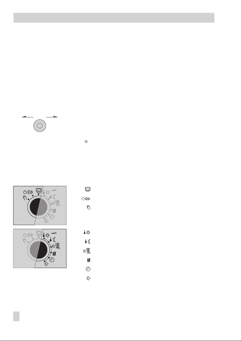
1.1 Operating controls
The operating controls are located in the front panel of the controller.
1.1.1 Rotary pushbutton
Rotary pushbutton
–
*
+
Turn [q]:
Display, select parameters and function blocks
Press [ ]:
Confirm adjusted selection or settings
1.1.2 Rotary switch
The rotary switchis usedto setthe operatingmode andthe relevantparameters foreach control
circuit.
Information level, rotary switch in normal position
Operating modes
Manual level
6 EB 5573 EN
Day set point (rated room temperature)
Night set point (reduced room temperature)
Times-of-use for heating/DHW
Party mode
Controller time
Configuration and parameter level
Page 7

Operation
1.2 Operating modes
Day mode (rated operation) : Regardless of the programmed times-of-use and summer
mode, the set points relevant for rated operation are used by the controller.
Night mode(reduced operation) : Regardlessof the programmed times-of-use, the set points
relevant for reduced operation are used by the controller.
Stand-by mode : Regardless of the programmed times-of-use, control operation is deacti
vated. Only the frost protection is activated, if need be.
Automatic mode : During the programmed times-of-use, the controllerworks in rated opera
tion. Outside these times-of-use, the controller is in reduced operation, unless control operation
is deactivateddepending on the outdoor temperature. The controller switches automatically be
tween both operating modes.
Manual mode : Valves and pumps can be controlled manually (–> section 3).
1.2.1 Setting the operating modes
1. Turn the rotary switch to (operating modes). blinks on the display.
For systems with just one control circuit (e.g. Anl 1.0), steps 2 and 3 can be skipped
4
(selecting the control circuit).
2. Select the control circuit whose operating mode is to be set [q]:
Heating circuit 1
Heating circuit 2
DHW circuit/circulation pump (DHW)
Only those control circuits are available for selection which can be controlled by the
4
system schematics (Anl) selected.
3. Confirm the control circuit [ ].
4. Select the operating mode [q]: , , or
5. Confirm the operating mode [ ].
6. Return the rotary switch to normal switch position (information level).
-
-
-
Note: Inautomatic mode, the momentary stage of the operating schedule( for day mode or
for night mode) is displayed in the information level together with the icon .
EB 5573 EN 7
Page 8
Operation
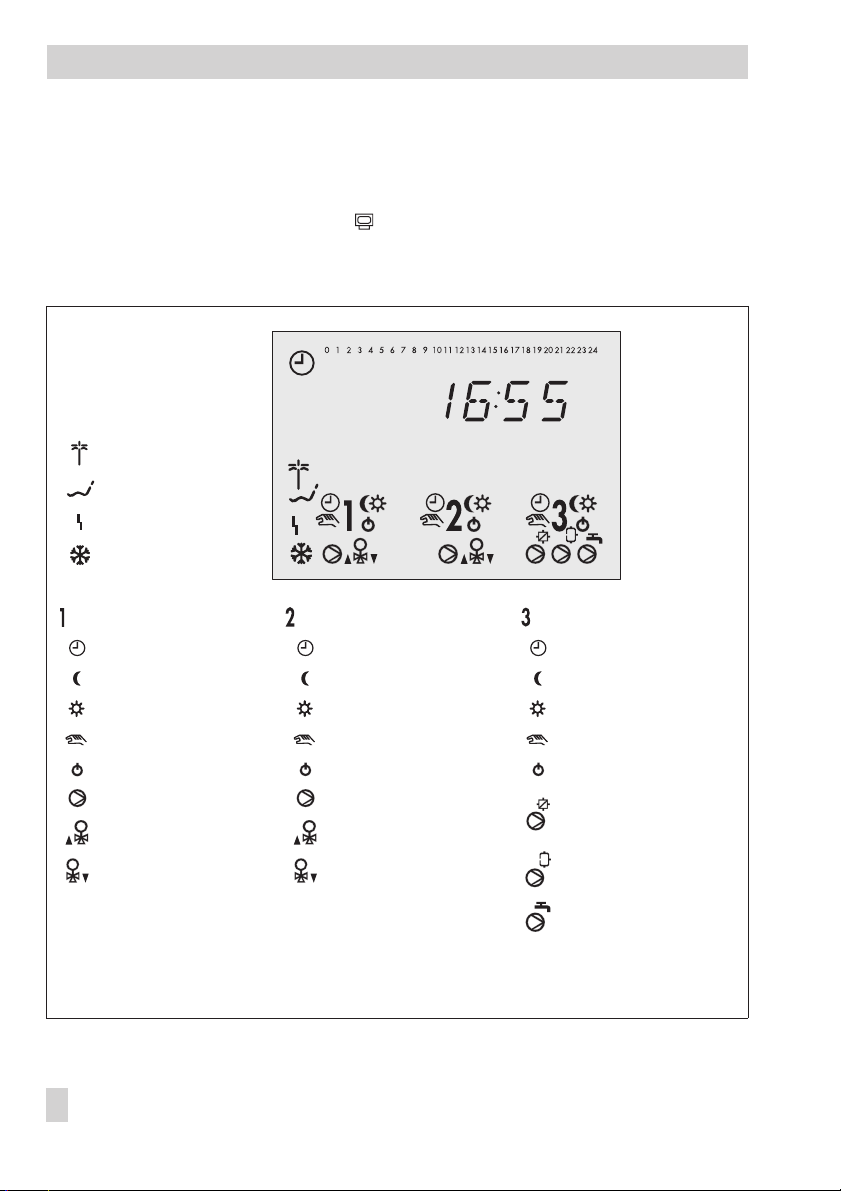
1.3 Display
The display indicates the time as well as information about the operation of the controller when
the rotary switch is at the normal position (information level). The times-of-use together with
temperatures of the various control circuits can be viewed on the display by turning the rotary
pushbutton. Thetimes-of-use are represented by black squares below the rowof numbers at the
top of the display. Icons indicate the operating status of the controller.
Public holiday mode
Vacation mode
Operational fault
Frost protection
Heating circuit 1 Heating circuit 2 DHW circuit
Automatic mode Automatic mode Automatic mode
Night mode Night mode Night mode
Day mode Day mode Day mode
Manual mode Manual mode Manual mode
Stand-by mode Stand-by mode Stand-by mode
Circulation pump UP1* Circulation pump UP2*
Valve Rk1 OPEN Valve Rk2 OPEN
Pump output TLP/CP*
Valve Rk1 CLOSED Valve Rk2 CLOSED
* UP1, UP2, TLP, CP, SLP and ZP indicate possible choices for pump selection in manual mode.
Fig. 1 · Icons
Storage tank charging
pump SLP*
Circulation pump ZP*
The controller status can be displayed in the information level (–> section 1.4).
8 EB 5573 EN
Page 9

1.4 Opening the information level
Operation
At the normal switch position (information level), the time, date, public holidays and vaca
tion periods as well as the temperaturesmeasured by the connected sensorsand their set points
can be retrieved and displayed.
Note: Data can also be viewed in the operating level (manual mode).
To do so, select Info, confirm and proceed as described below.
Proceed as follows:
1. Select value [q].
Depending on the configuration of the controller, the current values of the following
data points are displayed one after the other:
__:__ Time
Room temperature, heating circuits 1, 2
Outdoor temperature
Temperature at flow sensor VF, heating circuits 1, 2
Temperature at flow sensor VF1, primary heat exchanger circuit
Temperature at flow sensor VF2, VF4, DHW circuit
Temperature at solar collector sensor VF3
-
Temperature at return flow sensor RüF
Temperature at storage tank sensor SF1
Temperature at storage tank sensor SF2
Temperature at storage tank sensor of the solar circuit
2. By confirming a data point [ ] its set point/limit is displayed. When the time is indicated
on the display, the date appears on pressing the rotary pushbutton.
EB 5573 EN 9
Page 10
Operation
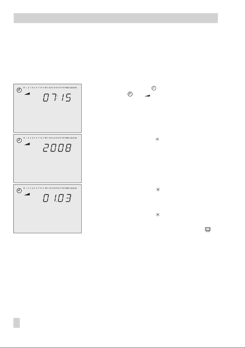
1.5 Setting the controller time
The current time and date need to be set immediately after start-up and after a power failure of
more than 24 hours has occurred. This is the case when the time blinks on the display.
Proceed as follows:
1. Turn the rotary switch to (controller time).
Display: time, and blink.
2. Edit the controller time [q].
3. Confirm the adjusted time [ ].
Display: year
4. Edit the year [q].
10 EB 5573 EN
5. Confirm the adjusted year [ ].
Display: date (day.month)
6. Edit the date [q].
7. Confirm the adjusted date [ ].
Display: time
8. Return the rotary switch to normal switch position
(information level).
Page 11

1.6 Setting the times-of-use
Three times-of-use can be set for each day of the week.
Parameters
Period/day 1–7 1–7, 1, 2, 3, 4, 5, 6, 7 with 1–7 = every day,
Start first time-of-use 6:00 0:00 to 24:00h; in steps of 15 minutes
Stop first time-of-use 22:00 0:00 to 24:00h; in steps of 15 minutes
Start second time-of-use 22:15 0:00 to 24:00h; in steps of 15 minutes
Stop second time-of-use 22:15 0:00 to 24:00h; in steps of 15 minutes
Start third time-of-use – 0:00 to 24:00h; in steps of 15 minutes
Stop third time-of-use – 0:00 to 24:00h; in steps of 15 minutes
* Default values (WE) valid for heating circuits
Proceed as follows:
1. Turn the rotary switch to (times-of-use).
blinks.
For systems with just one control circuit (e.g. Anl 1.0), steps 2 to 5 can be skipped
4
(selecting the control circuit and specifying the DHW circuit).
Only the DHW circuit is controlled in systems Anl 1.5 and 1.9. Therefore the instruc-
4
tions steps 2 and 3 (selecting the control circuit) do not apply and can be skipped.
2. Select the control circuit, for which the times-of-use are to be entered [q]:
Heating circuit 1
Heating circuit 2
DHW circuit/circulation pump (DHW)
Only those control circuits are available for selection which can be controlled by the
4
system (Anl) selected.
3. Confirm the control circuit [ ].
If control circuit 1 or 2 has been selected, skip steps 4 and 5.
4
4. Specify DHW circuit [q]:
WE* Range of values
1 = Monday, 2 = Tuesday, ..., 7 = Sunday
Operation
DHW heating / Circulation pump (DHW)
5. Confirm [ ].
EB 5573 EN 11
Page 12
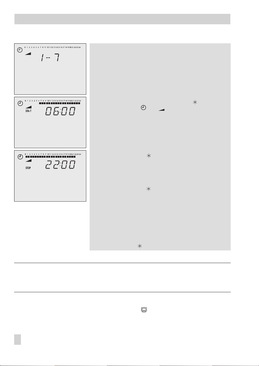
Operation
6. Select period/day for which the times-of-use are to be
valid [q]:
1–7 = every day,
1 = Monday, 2 = Tuesday, ..., 7 = Sunday
7. Activate editing mode for period/day [ ].
START
Display:
8. Edit start time [q].
(in steps of 15 minutes)
9. Confirm start time [ ].
Display:
10. Edit stop time [q].
(in steps of 15 minutes)
11. Confirm stop time [ ].
Display:
The indicated time corresponds to the stop time for the
first time-of-use plus 15 minutes.
To set the second and third times-of-use, repeat steps 8
to 11.
If no further times-of-use for the selected period/day
are to be programmed, confirm the displayed start
time twice (2x [ ]).
For daily setting, repeat steps 6 to 11 in the same sequence.
, and blink.
STOP
START
Note: Do not use the 1–7 menu to check the programmed times-of-use.
If this menu is opened after the times-of-use have been set, the schedule programmed for Mon
day is also adopted for all other days of the week.
12. After setting all times-of-use:
Return the rotary switch to normal switch position (information level).
12 EB 5573 EN
-
Page 13

Operation
1.7 Setting the party mode
Using the Party mode function, the controller continues or activates the day mode during the
time when theparty timeris active,regardless ofthe programmedtimes-of-use. When the party
timer has elapsed, the party mode timer is reset to 00:00.
Parameter
Continue/activate rated operation 0 h 0 to 48 hours
Proceed as follows:
1. Turn the rotary switch to (party mode).
blinks.
In systems Anl 1.0, 1.9 and 3.5, the display reads 00:00 or indicates the remaining
4
time of party timer. Steps 2 and 3 can be skipped (selecting the control circuit).
2. Select the control circuit in which the day mode is to continue or be activated [q]:
Heating circuit 1
Heating circuit 2
DHW circuit
Only those control circuits are available for selection which can be controlled by the
4
system (Anl) selected.
3. Confirm the control circuit [ ].
00:00
Display:
4. Select how long the day mode is to continue running [q].
This setting is made in steps of 15 minutes.
5. Return the rotary switch to normal switch position (information level).
Note: The party timer counts down in steps of 15 minutes.
or indicates the remaining time of party timer.
WE Range of values
EB 5573 EN 13
Page 14
Operation
1.8 Activating the extended information level
If the extended information level is activated, further information can be viewed after the listed
data points:
Public holidays (can be changed, see section 1.8.1)
4
Vacation periods (can be changed, see section 1.8.2)
4
Valve positions
4
Switching states of the binary inputs
4
InFo 2: After confirming the level [ ] the following data appear in the sequence shown be
4
low:
Controller ID
Memory capacity of data logging module (section 9.5)
255
Operating hours of solar circuit pump (referto section6.4)
Opening the extended information level:
1. Turn the rotary switch to (parameter and configuration level).
0 0 0 0
Display:
2. Set key number 1999 [q].
3. Confirm key number [ ].
Display:
4. Return the rotary switch to normal switch position (information level).
, blinks.
0 0 0 0
-
Note: The extended information level is deactivated when the key number 1999 is re-entered.
14 EB 5573 EN
Page 15
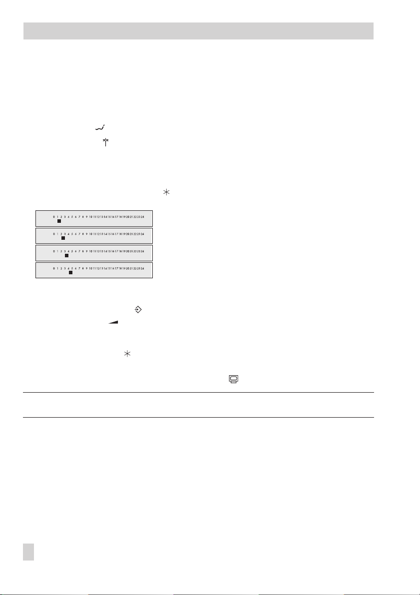
1.8.1 Setting public holidays
On public holidays, the times-of-use specified for Sunday apply.
A maximum of 20 public holidays may be entered.
Parameter WE Level / Range of values
Public holidays – Extended information level/ 01.01 to 31.12
Proceed as follows:
1. In the extended information level (normal switch
position ) select data point for public holidays [q].
Display:
2. Open data point for public holidays.
– – – –
3. If applicable, select
4. Activate editing mode for public holiday [ ].
and blink.
5. Select public holiday [q].
6. Confirm public holiday [ ].
To enter additional public holidays, re-select – – . – – and repeat the steps 4 to 6.
.
Operation
Note: Public holidays can also be set in PA5 parameter level (–> section 2.3).
Deleting a public holiday:
1. Under data point for public holidays, select the holiday you wish to delete [q].
2. Confirm selection [ ].
3. Select – –.– – [q].
4. Confirm selection [ ].
The public holiday is deleted.
Note: Public holidays that are not assigned to a specific date should be deleted by the end of the
year so that they are not carried on into the following year.
EB 5573 EN 15
Page 16
Operation
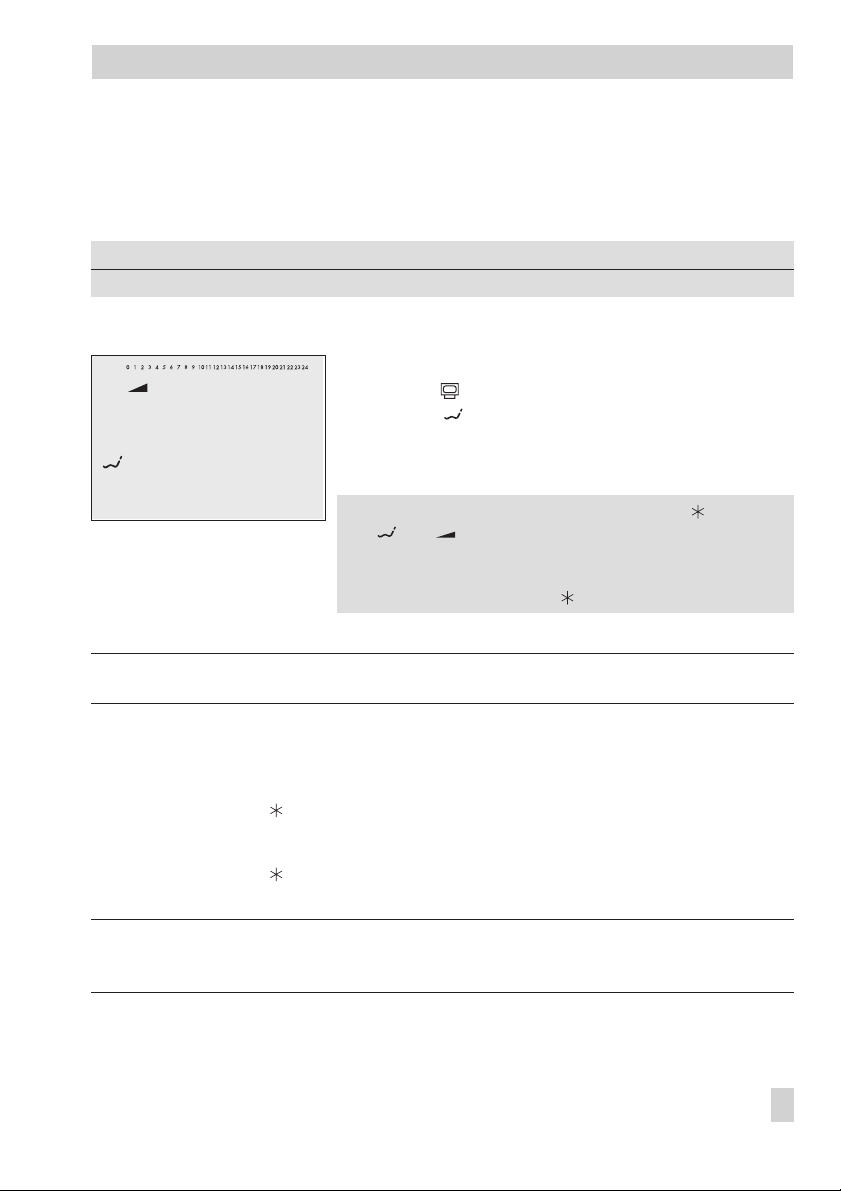
1.8.2 Setting vacation periods
During vacation periods, the controller constantly remainsin reducedoperation. Amaximum of
10 vacation periods can be entered. Each vacation period can be separately assigned to the
heating circuits Rk1, Rk2 and/or the DHW circuit.
Parameter WE Level / Range of values
Vacation period (START, STOP) – Extended information level / 01.01 to 31.12
Proceed as follows:
1. In the extended information level (normal switch
position ) select data point for vacation periods [q].
Display:
2. Open data point for vacation periods [ ].
Display:
3. If applicable, select
4. Activate editing mode for start date of vacation period
[].
5. Edit start date of vacation period [q].
6. Confirm start date of the vacation period.
Display:
7. Edit end of vacation period [q].
8. Confirm end of vacation period [ ].
The black square at the top of the display indicate the
assignment of the vacation periods to the individual
control circuits.
9. Select the control circuit to which the current vacation
period should apply [q].
The vacation period can be assigned to a single con
trol circuit or any combination of all three circuits
(Rk1, Rk2, DHW circuit).
To enter additional vacation periods, re-select
START
– – – –
and blink.
[q].
STOP, – –.– –
Current vacation period applies to heating circuit 1
Current vacation period applies to heating circuit 2
–
Current vacation period applies to DHW circuit
– –.– –
and repeat the steps 4 to 9.
-
16 EB 5573 EN
Page 17

Note: Vacation periods can also be set in PA5 parameter level (–> section 2.3).
Deleting vacation periods:
Operation
1. Under data point for vacation periods, select the start date of the period you wish to de
lete [q].
2. Confirm selection [ ].
3. Select
– –.– –
[q].
4. Confirm selection [ ].
The vacation period is deleted.
Note: Vacation periods should be deleted by the end of the year so that they are not carried on
into the following year.
-
EB 5573 EN 17
Page 18

Operation
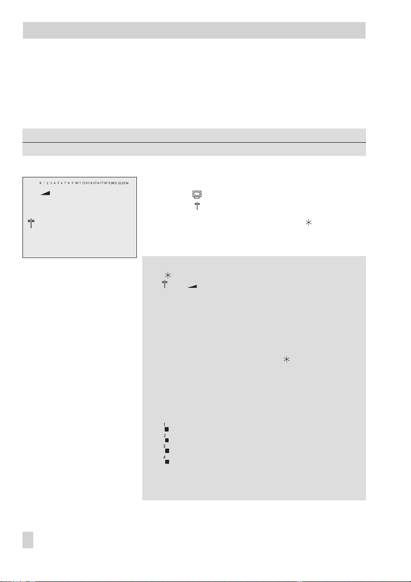
1.9 Entering day and night set points
The desired room temperature for the day (
the night (
In the DHW circuit, the temperature you wish the DHW to be heated to can be set.
Switch position
Parameters WE Range of values
Day set point Rk1, Rk2 20 °C 0 to 40 °C
DHW temperature set point 55 °C Min. to max. DHW temperature
Switch position
Parameters WE Range of values
Night set point Rk1, Rk2 20 °C 0 to 40 °C
DHW sustained temperature 40 °C Min. to max. DHW temperature
Proceed as follows:
1. Turn the rotary switch to the required data point:
2. Select the control circuit for which the set point is to be entered [q]:
3. Confirm the control circuit [ ].
4. Adjust set point [q].
5. Return the rotary switch to normal switch position (information level).
Night set point
for Day set point or DHW temperature set point
for Night set point or DHW sustained temperature
blinks.
In systems Anl 1.0, 1.9 and 3.5, the current set point is directly indicated. Skip the
4
following steps 2 and 3 (selecting the control circuit).
Heating circuit 1
Heating circuit 2
DHW circuit
Only those control circuits are available for selection which can be controlled by the
4
system (Anl) selected.
Display: current set point
) can be entered in the controller for the heating circuits.
Day set point
) and a reduced room temperature for
18 EB 5573 EN
Page 19

q
Information level
Operation
& key number
End PA1
Configuration and
parameter level
(start-up, see section 2)
CO4CO5
PA1/CO1: Rk1 (heating circuit 1)
PA2/CO2: Rk2 (heating circuit 2)
PA4/CO4: DHW circuit
PA5/CO5: System-wide parameters
PA6/CO6 Modbus communication
Anl: System code number
q
PA2Anl
PA4
PA5
PA6CO6
CO1CO2
Fig. 2 · Level structure of TROVIS 5573
EB 5573 EN 19
Page 20

Start-up
2 Start-up
The modifications of the controller configuration and parameter settings described in this sec
tion can only be performed after the valid key number has been entered.
The valid key number for initial start-up can be found on page 123. To avoid unauthorized use
of the key number, remove the page ormake the key number unreadable. In addition, it is pos
sible to enter a new, customized key number (–> section 7.15).
2.1 Setting the system code number
21 different hydraulic schematics are available. Each system configuration is represented by a
system code number. The different schematics are dealt with in section 4. Available controller
functions are described in sections 5, 6 and 7.
Changing the system code number resets previously adjusted function blocks to their default set
tings (WE). Function block parameters and parameter level settings remain unchanged.
The system code number is set in the configuration and parameter level.
Proceed as follows:
1. Turn the rotary switch to (configuration and parameter level).
Anl
blinks.
0 0 0 0
PA_
.
End
Display:
2. Set valid key number [q].
3. Confirm key number [ ].
Display:
4. Select
5. Activate editing mode for the system code number [ ].
6. Edit system code number [q].
7. Confirm system code number [ ].
Display:
8. Return the rotary switch to normal switch position (information level).
-
-
-
20 EB 5573 EN
Page 21

Start-up
2.2 Activating and deactivating functions
A function is activated or deactivated in the associated function block. The numbers 0 to 24 in
the top row of the display represent the respective function block numbers. When a configura
tion level is opened, the activated function blocks are indicated by a black square on the
right-hand side below the function block number. For more details on function blocks, refer to
section 12.1.
The functions are grouped by topics:
CO1: Rk1 (Heating circuit 1)
4
CO2: Rk2 (Heating circuit 2)
4
CO3: Not applicable
4
CO4: DHW circuit
4
CO5: System-wide functions
4
CO6: Modbus communication
4
1. Turn the rotary switch to (configuration and parameter level).
Display:
2. Set valid key number [q].
3. Confirm key number [ ].
Display:
4. Select configuration level [q].
5. Open configuration level [ ].
6. Select function block [q].
Activated function blocks are marked by “- 1“.
Deactivated function blocks are marked by “- 0“.
7. Activate editing mode for the function block [ ].
8. Activate the function block [q].
Display:
An activated function block is indicated by a black square below (right) the function
block number in the top row of the controller display.
or:
Deactivate the function block [q].
Display:
0 0 0 0
PA_
blinks.
F__ - 1
F__ - 0
-
EB 5573 EN 21
Page 22

Start-up
10. Confirm settings [ ].
If the function block is not closed, further function block parameters can be adjusted.
Proceed as follows:
a) Select function block parameter [q].
b) Confirm function block parameter [ ].
If applicable, the next function block parameter is displayed.
Confirm all parameters to exit the opened function block.
To adjust additional function blocks in the open configuration level, repeat the steps 6
to 10.
End
11. Select
12. Exit configuration level [ ].
To adjust additional function blocks in the other configuration levels, repeat 4 to 10.
13. Return the rotary switch to normal switch position (information level).
[q].
22 EB 5573 EN
Page 23

Start-up
2.3 Changing parameters
Depending on the set system code number and the activated functions, not allparameters listed
in the parameter list in the Appendix (–> section 12.2) might be available.
The parameters are grouped by topics:
PA1: Rk1 (Heating circuit 1)
4
PA2: Rk2 (Heating circuit 2)
4
PA3: Not applicable
4
PA4: DHW heating
4
PA5: System-wide parameters
4
PA6: Communication parameters
4
1. Turn the rotary switch to (configuration and parameter level).
blinks.
End
0 0 0 0
PA_
[q].
Display:
2. Set valid key number [q].
3. Confirm key number [ ].
Display:
4. Select parameter level [q].
5. Open parameter level [ ].
6. Select parameter [q].
7. Activate editing mode for the parameter [ ].
8. Edit the parameter [q].
9. Confirm the parameter [ ].
To adjust additional parameters in the open parameter level, repeat steps 6 to 9.
10. Select
11. Exit parameter level [ ].
To adjust additional parameters in another parameter level, repeat steps 4 to 9.
12. Return the rotary switch to normal switch position (information level).
EB 5573 EN 23
Page 24

Start-up
2.4 Calibrating sensors
The controller is designed for the connection of Pt 1000 sensors.
The resistance values of the Pt 1000 sensors can be found on page 112.
If the temperature values displayed at the controller differ from the actual temperatures, the
measured values of all connectedsensors canbe readjusted.To calibratea sensor,the currently
displayed sensor value must be changed such that it matches the temperature (reference tem
perature) measured directly at the point of measurement.
Sensor calibration is to be activated in CO5 via function block F20.
An incorrect sensor calibration can be deleted by setting F20 - 0.
Proceed as follows:
1. Turn the rotary switch to (configuration and parameter level).
Display:
2. Set valid key number [q].
3. Confirm valid key number [ ].
Display:
4. Select CO5 configuration level [q].
5. Open CO5 configuration level [ ].
6. Select function block F20 [q].
7. Activate editing mode for function block F20 [ ].
8. Select appropriate sensor icon [q]:
0 0 0 0
PA_
-
24 EB 5573 EN
Room sensor RF, heating circuits 1 and 2
Outdoor sensor AF1
Flow sensor VF, heating circuits 1 and 2
Flow sensor VF1, primary heat exchanger circuit
Flow sensors VF2 and VF4, DHW circuit
Solar collector sensor VF3
Return flow sensor RüF
Page 25

Start-up
Storage tank sensor SF1
Storage tank sensor SF2
Storage tank sensor of the solar circuit SF2
9. Display measured value [ ].
“°C” blinks.
10. Correct measured value [q].
Read the actual temperature directly from the thermometer at the point of measurement
and enter this value as the reference temperature.
11. Confirm corrected measured value [ ].
Additional sensors are calibrated similarly.
End
12. Select
13. Return the rotary switch to normal switch position (information level).
[q].
2.5 Resetting to default values
All parameters set over the rotary switchas wellas parametersin PA1, PA2 and PA5 parameter
levels can be reset to their default settings (WE), except for the maximum flow temperature and
the return flow temperature limits in PA1 and PA2.
1. Turn the rotary switch to (configuration and parameter level).
Display:
2. Set key number 1991 [q].
3. Confirm key number [ ].
The controller is reset to its default settings.
Display:
0 0 0 0
0 0 0 0
EB 5573 EN 25
Page 26

Manual mode
3 Manual mode
Switch to manual mode to configure all outputs, refer to wiring diagram (-> section 11).
NOTICE
The frost protection does not function when the controller is in manual mode.
Proceed as follows:
1. Turn the rotary switch to (manual level).
2. Select output depending on the control circuit (q):
POS_ Positioning value in percent
UP_ Activation/deactivation of the circulation pump (heating)
SLP Activation/deactivation of the storage tank charging pump
TLP Activation/deactivation of the heat exchanger charging pump
CP Activation/deactivation of the solar circuit pump
ZP Activation/deactivation of the circulation pump (DHW)
3. Confirm the output [ ].
The display blinks.
4. Change positioning value/switching state [q].
5. Confirm setting [ ].
The modified values remain active as long as the controller is in manual mode.
6. Return the rotary switch to normal switch position (information level).
The manual mode is deactivated.
Note: The outputs of the controller are not affected by simply turning the rotary switch to
(manual level). You have to actually enter a positioning value or activate/deactivate the pumps
to configure the outputs.
26 EB 5573 EN
Page 27
Systems
4 Systems
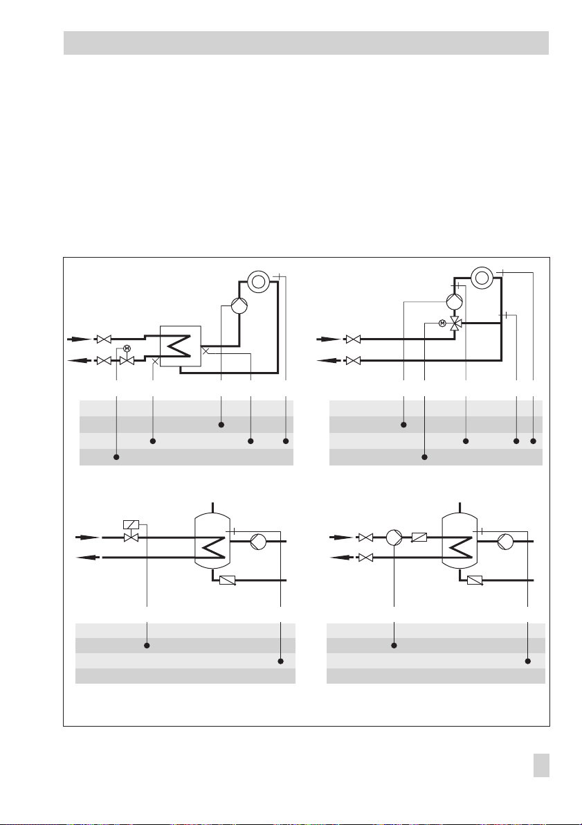
21 different hydraulic schematics are available.
The systems can be configured both as primary and secondary systems. The fundamental hy
draulic differences between a primary and a secondary system are illustrated in Fig. 3.
1. mixing valve replaces the heat exchanger in the heating/DHW circuit.
4
2. A storage tank charging pump replaces the primary solenoid/thermoelectric valve.
4
The controller settings do not have to be changed.
1.
Primary system
RüF1 VF1UP1RK1 RK1RF1 VF1UP1 RüF1 RF1
BE
BA
AE
RK
Secondary system
BE
BA
AE
RK
-
2.
Primary system Secondary system
BE
BA
AE
RK
Fig. 3 · Differences between primary and secondary systems
WW
KW
SF1SLP
BE
BA
AE
RK
WW
KW
SF1SLP
EB 5573 EN 27
Page 28
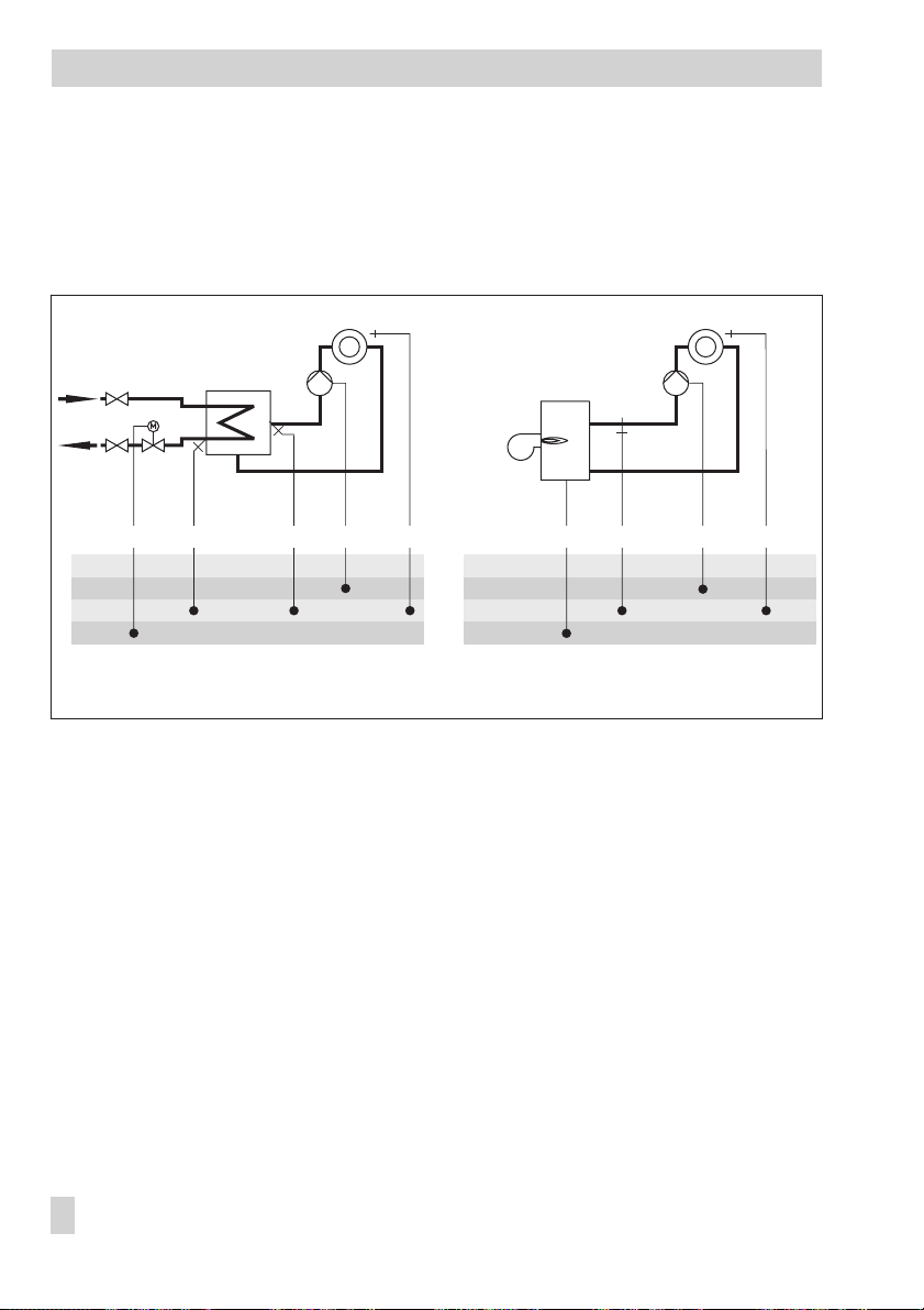
Systems
Boiler systems:
Single-stage boiler systems can be configured toinclude any system whose heatingcircuits and
DHW circuit include just one heat exchanger. These systems are Anl 1.0, 1.5, 1.6, 2.x, 3.0,
3.5, 4.0 and 4.1.
The boiler can be controlled by an on/off output (CO1 -> F12 - 0).
Boiler
single-stage
RK1 RüF1 VF1 UP1 RF1
BE
BA
AE
RK
Fig. 4 · Configuration of a boiler system
RK1_2 Pkt VF1 UP1 RF1
BE
BA
AE
RK
28 EB 5573 EN
Page 29
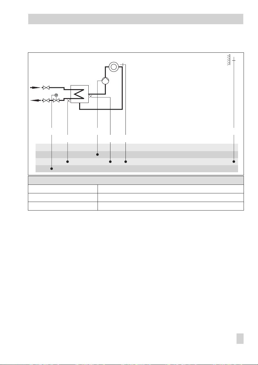
System Anl 1.0
Systems
UP1RK1
RüF1 VF1
BE
BA
AE
RK
RF1
Default settings
CO1 -> F01 - 0 (without RF1)
CO1 -> F02 - 1 (with AF1)
CO1 -> F03 - 1 (with RüF1)
AF1
EB 5573 EN 29
Page 30
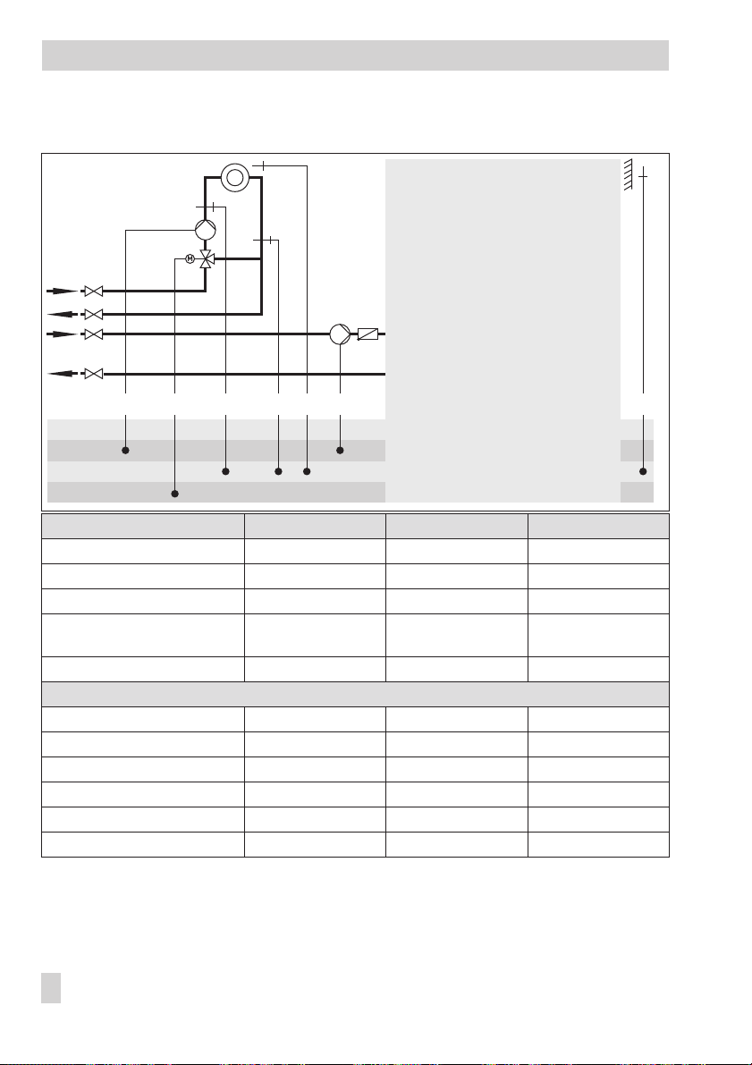
Systems
Systems Anl 1.1 to 1.3
DHW
heating
Unfold back cover!
UP1 XX
BE
BA
AE
RK
1)
AF1 RK1 VF1 RüF1 RF1
System Anl 1.1 Anl 1.2 Anl 1.3
Type of DHW heating Type 1 Type 2 Type 3
1)
XX = SLP TLP SLP
Integration of flow sensor VF4 Possible Possible –
ZP integration with
CO4 -> F10 - 1 (broken line)
Note
– Not possible –
–
Secondary system only
–
Default settings
CO1 -> F01 - 0 (without RF1) - 0 (without RF1) - 0 (without RF1)
CO1 -> F02 - 1 (with AF1) - 1 (with AF1) - 1 (with AF1)
CO1 -> F03 - 1 (with RüF1) - 0 (without RüF1) - 1 (with RüF1)
CO4 -> F01 - 1 (with SF1) - 1 (with SF1) - 1 (with SF1)
CO4 -> F02 - 0 (without SF2) - 1 (with SF2) - 0 (without SF2)
CO4 -> F05 - 0 (without VF4) - 0 (without VF4) - 0 (without VF4)
30 EB 5573 EN
Page 31

System Anl 1.5
Systems
WW
KW
SLP
BE
BA
AE
RK
RK1
RüF1
VF1 SF1
Default settings
CO1 -> F03 - 1 (with RüF1)
CO4 -> F01 - 1 (with SF1)
CO4 -> F02 - 0 (without SF2)
ZP
EB 5573 EN 31
Page 32

Systems
System Anl 1.6
WW
KW
RK1
UP1 VF1
RüF1
BE
BA
AE
RK
System Anl 1.6
with pre-control
VF4 SF1
SF2
Anl 1.6
without pre-control
Integration of VF4, UP1 Possible Not possible
ZP integration with
CO4 -> F10 - 1 (broken line)
Possible Possible
VF1 takes the position of VF4;
Note –
RüF1 is to be installed in the heat
exchanger
Default settings
CO1 -> F03 - 1 (with RüF1)
CO4 -> F01 - 1 (with SF1)
CO4 -> F02 - 1 (with SF2)
CO4 -> F05 - 0 (without VF4)
ZP SLP
32 EB 5573 EN
Page 33

System Anl 1.9
Systems
WW
KW
RK2
BE
BA
AE
RK
Default settings
CO4 -> F01 - 0 (without SF1)
CO4 -> F03 - 0 (without RüF2)
VF2
SF1RüF2
ZP
EB 5573 EN 33
Page 34

Systems
System Anl 2.0
WW
KW
SLP (RK2)
RK1
RüF1 VF1
BE
BA
AE
RK
UP1
RF1
Default settings
CO1 -> F01 - 0 (without RF1)
CO1 -> F02 - 1 (with AF1)
CO1 -> F03 - 1 (with RüF1)
CO4 -> F01 - 1 (with SF1)
CO4 -> F02 - 0 (without SF2)
AF1ZP
SF1
34 EB 5573 EN
Page 35

Systems Anl 2.1 to 2.3
Systems
DHW
heating
Unfold back cover!
BE
BA
AE
RK
UP1RK1
RüF1 VF1
RF1
XX
1)
AF1
System Anl 2.1 Anl 2.2 Anl 2.3
Type of DHW heating Type 1 Type 2 Type 3
1)
XX = SLP TLP SLP
Integration of VF4 Not possible Possible –
ZP integration with
CO4 -> F10 - 1 (broken line)
– Not possible –
Default settings
CO1 -> F01 - 0 (without RF1) - 0 (without RF1) - 0 (without RF1)
CO1 -> F02 - 1 (with AF1) - 1 (with AF1) - 1 (with AF1)
CO1 -> F03 - 1 (with RüF1) - 1 (with RüF1) - 1 (with RüF1)
CO4 -> F01 - 1 (with SF1) - 1 (with SF1) - 1 (with SF1)
CO4 -> F02 - 0 (without SF2) - 1 (with SF2)
CO4 -> F05 - 0 (without VF4)
EB 5573 EN 35
Page 36

Systems
System Anl 3.0
RK2RK1
RüF1 VF1 UP2
BE
BA
AE
RK
RüF2UP1 UP1
VF2
RF2
Default settings
CO1 -> F02 - 1 (with AF1)
CO1 -> F03 - 1 (with RüF1)
CO2 -> F01 - 0 (without RF2)
CO2 -> F03 - 0 (without RüF2)
AF1
36 EB 5573 EN
Page 37

System Anl 3.5
RK1/Y1 UP1
RüF1 VF1
BE
BA
AE
RK
Systems
Note
Closed control loop and UP1 are only active during the processing
for an external demand
Default settings
CO1 -> F03 - 1 (with RüF1)
EB 5573 EN 37
Page 38

Systems
System Anl 4.0
VF1
RK2RK1
RüF1
BE
BA
AE
RK
UP2
Default settings
CO1 -> F01 - 0 (without RF1)
CO1 -> F02 - 1 (with AF1)
CO1 -> F03 - 1 (with RüF1)
CO2 -> F01 - 0 (without RF2)
CO2 -> F03 - 0 (without RüF2)
VF2
RüF2
RF2
UP1
RF1
AF1
38 EB 5573 EN
Page 39

System Anl 4.1
VF1
RK2RK1
RüF1
BE
BA
AE
RK
UP2
Default settings
CO1 -> F01 - 0 (without RF1)
CO1 -> F02 - 1 (with AF1)
CO1 -> F03 - 1 (with RüF1)
CO2 -> F01 - 0 (without RF2)
CO2 -> F03 - 0 (without RüF2)
CO4 -> F01 - 1 (with SF1)
CO4 -> F02 - 0 (without SF2)
VF2
RüF2
RF2
UP1
RF1
SLP SF1
Systems
WW
KW
AF1
EB 5573 EN 39
Page 40

Systems
System Anl 4.5
VF1
RK2RK1
RüF1
BE
BA
AE
RK
UP2
Default settings
CO1 -> F01 - 0 (without RF1)
CO1 -> F02 - 1 (with AF1)
CO1 -> F03 - 1 (with RüF1)
CO2 -> F01 - 0 (without RF2)
CO2 -> F03 - 0 (without RüF2)
CO4 -> F01 - 1 (with SF1)
CO4 -> F02 - 0 (without SF2)
VF2
RüF2
RF2
UP1
RF1
WW
KW
AF1
SF1SLP
40 EB 5573 EN
Page 41

System Anl 10.0
Systems
BE
BA
AE
RK
VF2
VF1
UP2RK2
UP1RK1
RF1RüF2
RF2
Default settings
CO1 -> F01 - 0 (without RF1)
CO1 -> F02 - 1 (with AF1)
CO1 -> F03 - 1 (with RüF1)
CO2 -> F01 - 0 (without RF2)
CO2 -> F03 - 1 (with RüF2)
AF1RüF1
EB 5573 EN 41
Page 42

Systems
System Anl 11.0
WW
KW
VF1 UP1RK1 RK2 RF1
BE
BA
AE
RK
Default settings
CO1 -> F01 - 0 (without RF1)
CO1 -> F02 - 1 (with AF1)
CO1 -> F03 - 1 (with RüF1)
CO4 -> F03 - 0 (without RüF2)
AF1RüF1
SF1ZPRüF2
42 EB 5573 EN
Page 43

System Anl 11.1
UP1 RK1 VF1 RüF1 RF1 AF1 ZP SLPRüF2 VF2 SF1RK2
BE
BA
AE
RK
Default settings
CO1 -> F01 - 0 (without RF1)
CO1 -> F02 - 1 (with AF1)
CO1 -> F03 - 1 (with RüF1)
CO4 -> F01 - 1 (with SF1)
CO4 -> F02 - 0 (without SF2)
CO4 -> F03 - 0 (without RüF2)
Systems
WW
KW
EB 5573 EN 43
Page 44

Systems
System Anl 11.2
WW
KW
RK2 RF1
RK1
BE
BA
AE
RK
UP1 SF1
RüF2
VF2
Default settings
CO1 -> F01 - 0 (without RF1)
CO1 -> F02 - 1 (with AF1)
CO1 -> F03 - 1 (with RüF1)
CO4 -> F01 - 1 (with SF1)
CO4 -> F02 - 1 (with SF2)
CO4 -> F03 - 0 (without RüF2)
SF2
AF1
ZP SLPRüF1 VF1
44 EB 5573 EN
Page 45

System Anl 11.9
Systems
WW
KW
RK2 RF1
RüF1
BE
BA
AE
RK
VF1
UP1RK1
Default settings
CO1 -> F01 - 0 (without RF1)
CO1 -> F02 - 1 (with AF1)
CO1 -> F03 - 1 (with RüF1)
CO4 -> F01 - 0 (without SF1)
CO4 -> F03 - 0 (without RüF2)
VF2
SF1RüF2
ZP
AF1
EB 5573 EN 45
Page 46

Functions of the heating circuit
5 Functions of the heating circuit
Which controller functions are available depends on the selected system code number (Anl).
5.1 Weather-compensated control
When weather-compensated control is used, the flow temperature is controlled according to the
outdoor temperature. The heating characteristic in the controller defines the flow temperature
set point asa functionof theoutdoor temperature(–> Fig.5). The outdoor temperature required
for weather-compensated control can either be measured by an outdoor sensor or it can be re
ceived over an 0 to 10 V input.
[˚C]
t
VL
130
120
110
100
90
80
70
60
50
40
30
20
2.62.93.2
2.4
2.2
2.0
1.8
1.6
1.4
1.2
1.0
0.8
0.6
0.4
0.2
t
A
-20 [
-16-12-8-4048121620
C]
˚
t
Flow temperature
VL
t
Outdoor temperature
A
-
Fig. 5 · Gradient characteristics
Function WE Configuration
Outdoor sensor AF1 1 CO1 -> F02 - 1
Outdoor temperature received
over 0 to 10 V input
0
–20 °C
50 °C
CO5 -> F23 - 1
Lower transmission range / –30 to 100 °C
Upper transmission range / –30 to 100 °C
46 EB 5573 EN
Page 47

5.1.1 Gradient characteristic
Functions of the heating circuit
Basically, the following rule applies: a decrease in the outdoor temperature causes the flow tem
perature to increase in order to keep the room temperature constant.
By varyingthe parameters
Gradient
and
Level
, youcan adaptthe characteristic to your individ
ual requirements:
[°C]
t
VL
The gradient needs to be increased if the room temperature
drops when it is cold outside.
t
A
20 0 –20
[°C]
t
VL
[°C]
The gradient needs to be decreased if the room temperature
rises when it is cold outside.
t
A
20 0 –20
[°C]
t
VL
[°C]
The level needs to be increased and the gradient decreased if
the room temperature drops when it is mild outside.
-
-
20 0 –20
[°C]
t
VL
20 0 –20
t
A
[°C]
The level needs to be decreased and the gradient increased if
the room temperature rises when it is mild outside.
t
A
[°C]
EB 5573 EN 47
Page 48

Functions of the heating circuit
Outside the times-of-use, reduced set points are used for control:
The reduced flow set point is calculated as the difference between the adjusted values for
set point
The
its of the flow temperature. A separate gradient characteristic can be selected for the limitation
of the return flow temperature.
Examples for adjusting the characteristic:
4
4
4
4
Note: Particularly for control operation without room sensor, the room temperatures set for day
(Day set point) and night (Night set point) only become effective satisfactorily when the heating
characteristic has been adapted to the building/heating surface layout.
Function WE Configuration
4-point characteristic 0 CO1, 2 -> F11 - 0
Parameters WE Switch position / Range of values
Day set point 20.0 °C / 0.0 to 40.0 °C
Night set point 15.0 °C / 0.0 to 40.0 °C
Parameters WE Parameter level / Range of values
Gradient, flow 1.8* PA1, 2 / 0.2 to 3.2
Level, flow 0.0 °C PA1, 2 / –30.0 to 30.0 °C
Min. flow temperature 20.0 °C PA1, 2 / 5.0 to 130.0 °C
Max. flow temperature 90.0 °C* PA1, 2 / 5.0 to 130.0 °C
* With CO1, 2 -> F05 - 1, the following applies: Gradient, flow / 0.2 to 1.0 (1.0)
(rated room temperature) and
Max. flowtemperature
Old building, radiator design 90/70: Gradient approx. 1.8
New building, radiator design 70/55: Gradient approx. 1.4
New building, radiator design 55/45: Gradient approx. 1.0
Underfloor heating depending on arrangement: Gradient smaller than 0.5
and
Min. flowtemperature
Night set point
Max. flow temperature / 5.0 to 50.0 °C (50.0 °C)
(reduced room temperature).
parameters markthe upperand lowerlim
Day
-
48 EB 5573 EN
Page 49

Functions of the heating circuit
5.1.2 4-point characteristic
t
[˚C]
VL
100
t
VLmax
90
t
VLmin
80
70
60
50
40
30
20
10
P2
P3
P4
P1
Fig. 6 · 4-point characteristic
The 4-point characteristic allows you to define your own heating characteristic.
It is defined by 4 points for the
and the
temperature
parameters mark the upper and lower limits of the flow temperature.
ture
Return flow temperature
Outdoor temperature
. The
Max. flow temperature
P1 to P4 Points 1 to 4
t
VL
t
A
---min Min. t
---max Max. t
t
A
[˚C]20 15 10 5 0 –5 –10 –15 –20
, the
Flow temperature,
Flow temperature
Outdoor temperature
VL
VL
4-point characteristic
Reduced 4-point characteristic
the
and
Min. flow tempera-
Reduced flow
Note:
Day set point
The
and
Night set point
parameters are no longer available when the 4-point
characteristic has been selected, provided no additional functions (e.g. Optimization, Flash
adaptation) have been selected.
The 4-point characteristic function can only be activated when the Adaptation function is not
active (CO1, 2 -> F08 - 0).
Functions WE Configuration
Adaptation 0 CO1, 2 -> F08 - 0
4-point characteristic 0 CO1, 2 -> F11 - 1
Parameters
Outdoor
temperature
Point 1
Point 2
Point 3
Point 4
WE Parameter level / Range of values
–15.0 °C
PA1, 2 / –40.0 to 50.0 °C
–5.0 °C
5.0 °C
15.0 °C
EB 5573 EN 49
Page 50

Functions of the heating circuit
Parameters
Flow
temperature
Reduced flow
temperature
Return flow
temperature
Min. flow temperature 20.0 °C PA1, 2 / 5.0 to 130.0 °C
Max. flow temperature 90.0 °C* PA1, 2 / 5.0 to 130.0 °C
* With CO1, 2 -> F05 - 1, the following applies: Max. flow temperature / 5 to 50 °C (50 °C)
Point 1
Point 2
Point 3
Point 4
Point 1
Point 2
Point 3
Point 4
Points 1 to 4 65.0 °C PA1, 2 / 5.0 to 90.0 °C
WE Parameter level / Range of values
70.0 °C
55.0 °C
40.0 °C
25.0 °C
60.0 °C
40.0 °C
20.0 °C
20.0 °C
PA1, 2 / 5.0 to 130.0 °C
PA1, 2 / 5.0 to 130.0 °C
5.2 Fixed set point control
During the times-of-use, the flow temperature can be controlled according to a fixed set point.
Outside the times-of-use, the controller regulates to a reduced flow temperature.
Set the desired rated flow temperature as
Night set point
Functions WE Configuration
Outdoor sensor AF1 1 CO1 -> F02 - 0
Parameters WE Switch position / Range of values
Day set point 50.0 °C / Min. to max. flow temperature
Night set point 30.0 °C / Min. to max. flow temperature
Parameters WE Parameter level / Range of values
Min. flow temperature 20.0 °C PA1, 2 / 5.0 to 130.0 °C
Max. flow temperature 90.0 °C PA1, 2 / 5.0 to 130.0 °C
.
Day set point
, and the reduced flow temperature as
Note: A fixed setpoint controlin heatingcircuit 2can onlybe configuredwith CO2-> F02 - 0 if
CO1 -> F02- 0is alsoconfigured as heating circuit 2 configured with CO2 -> F02 - 0 only uses
the measured outdoor temperature provided by heating circuit 1.
50 EB 5573 EN
Page 51

Functions of the heating circuit
5.3 Underfloor heating/drying of jointless floors
Using function block settingCO1, 2-> F05- 1,the respectiveheating circuitis configuredas an
underfloor heating circuit. In doing so, the controller at first only limits the value ranges of the
heating characteristic gradient and the maximum flowtemperature inPA1, 2 parameter levels:
Value range of the gradient: 0.2 to 1.0
4
Value range of the maximum flow temperature: 5 to 50 °C
4
In addition, it is possible to activate the Drying of jointless floors function. In connection with
this, the function block parameters are listed which appear after activating this function block.
They determine the drying process: the firstheating upphase starts at the entered
, which has a flow temperature of 25 °C in its default setting. In the course of 24 hours, this
ture
temperature is raisedby thevalue enteredin
flow temperature set point to rise to 30 °C. If the
constant for the number of days entered in
Temperature reduction
reduction
is set to 0, the temperature maintaining phase moves directly to automatic mode.
determines the temperature reduction downwards. If the
Temperature rise
Maximum temperature
Maintaining time for maximum temperature
The drying function is activated by changing the setting
n
STArT
phase (
nn
(
STArT
on the display). The restarting stages
on the display) and
START temperature reduction phase
, i.e. thedefault settingcauses the
STOPtoSTART temperature build-up
START temperature maintaining phase
nnn
(
can be selected to continue an interrupted drying process. The course of the drying process can
be monitoredin theinformation level over the icon of flow temperature display ( ) of theassociated heating circuit:
Start tempera
is reached, it is kept
Temperature
STArT
on the display)
-
. The
Temperature build-up phase
r
Temperature maintaining phase
r
Temperature reduction phase
r
The drying process has been successfully completed when the additional icon in the flow tem
perature display goes out after the last phase.
STOP
on the display indicates that there has been a deviation of flow temperature of more than
5 °C for longer than 30 minutes. The function is canceled by the controller in such cases. While
STOP
appears on the display, the controller keeps the flow temperature constant at 25 °C.
EB 5573 EN 51
-
Page 52

Functions of the heating circuit
A power failure while the drying function is active or when
STOP
appears on the display auto
matically leads to the drying function restarting from the beginning.
In systems in which the drying function had to be interrupted due to DHW heating (e.g.
Anl 2.1), storage tank charging does not occur while thedrying function is active, provided it is
not used for frost protection of the storage tank.
NOTICE
The function block parameter can only be accessed when the function has started by deactivat
ing the function block and activating it again.
Functions WE Configuration
Underfloor heating
Drying of jointless floors
0
25 °C
5.0 °C
45.0 °C
4
0.0 °C
SToP
CO1, 2 -> F05 - 1
Start temperature / 20 to 60 °C
Temperature rise per day / 1.0 to 10.0 °C
Maximum temperature / 25.0 to 60.0 °C
Maintaining time for max. temperature / 0 to 10 days
Temperature reduction per day / 0.0 to 10.0 °C
n
STArT,nnSTArT,
nnn
STArT
5.4 Deactivation depending on outdoor temperature
5.4.1 OT deactivation value in rated operation
If theoutdoor temperature exceeds the limit
heating circuit is put out of service immediately. The valve is closed and the pump is switched off
after t = 2 x valve transit time. When the outdoor temperature falls below this value (less 0.5 °C
hysteresis), heating operation is restarted immediately.
With the default settings, this means that, during the warm season, the system is switched off at
an outdoor temperature of 22 °C.
Parameter WE Parameter level / Range of values
OT deactivation value
in rated operation
22.0 °C PA1, 2 / 0.0 to 50.0 °C
OT deactivationvalue in rated operation
, theaffected
-
-
5.4.2 OT deactivation value in reduced operation
If the outdoor temperature exceeds the limit value
reduced operation, the affected heating circuit is put out of service immediately.
52 EB 5573 EN
OT deactivation value in reduced operation
in
Page 53

Functions of the heating circuit
The valve is closed and the pump is switched off aftert=2xvalve transit time. When the out
door temperature falls below this value (less 0.5 °C hysteresis), heating operation is restarted
immediately.
With the default settings, this means that, at night, the system is switched off at an outdoor tem
perature of 15 °C tosave energy.Nevertheless, rememberthat thesystem requiressome timein
the morning to heat up the building.
Parameter WE Parameter level / Range of values
OT deactivation value
in reduced operation
15.0 °C PA1, 2 / –20.0 to 50.0 °C
5.4.3 OT activation value in rated operation
If a heating circuit is in reduced operation (automatic mode), the circuit is automatically trans
ferred to ratedoperation whenthe outdoortemperature fallsbelow thelimit value
value inrated operation
. Whenthe limit value is exceeded (plus 0.5 °C hysteresis), reducedop-
OT activation
eration is restarted.
This function is activated at very low temperatures to avoid that the building cools down exces-
sively outside the times-of-use when low outdoor temperatures occur.
Parameter WE Parameter level / Range of values
OT activation value
in rated operation
–15.0 °C PA1, 2 / –20.0 to 5.0 °C
5.4.4 Summer mode
Summer mode is activated depending on the mean daytime temperature (measured between
7.00h and 22.00h) during the desired period.
If the mean daytime temperature exceeds the
OT limit value in summer mode
days, summer mode is activated on the following day. This means that the valves in all heating
circuits are closed and the circulation pumps are switched off aftert=2xvalve transit time. If
the mean daytime temperature remains below the
OT limit value in summer mode
sive days, summer mode is deactivated on the following day.
Function WE Configuration
Summer mode 0
01.06
2
30.09
1
18.0 °C
CO5 -> F04 - 1
Start summer mode/ 01.01 (1 Jan) to 31.12 (31 Dec)
No. of days until activation / 1 to 3
Stop summer mode / 01.01 to 31.12
No. of days until deactivation / 1 to 3
OT limit value summer mode / 0 to 30 °C
on n successive
on m succes
-
-
-
-
EB 5573 EN 53
Page 54

Functions of the heating circuit
Note: Summer mode only becomes effective when the controller is in automatic mode ( ).
5.5 Delayed outdoor temperature adaptation
The calculated outdoor temperature is used to determine the flow temperature set point. The
heat response is delayed when the outdoor temperature either decreases, increases or in
creases and decreases. If the outdoor temperature varies by, for example, 12 °C within a very
short period of time, the calculated outdoor temperature is adapted to the actual outdoor tem
Delay
perature in small steps. Assuming a
of 3 °C/h, the adaptation would take
Note:
The delayed outdoor temperature adaptation helps avoid unnecessary overloads of central
heating stationsin combination with either overheated buildings occurring, forexample, due to
warm winds, or temporarily insufficient heating due to the outdoor sensor being exposed to direct sunshine.
In the information level, the outdoor temperature blinks on the display while delayed outdoor
temperature adaptation is active. The calculated outdoor temperature is displayed.
Functions WE Configuration
Delayed OT adaptation when OT decreases 0 CO5 -> F05 - 1
C
°°12
th
==
Ch
3
.
4
/
-
-
Delayed OT adaptation when OT increases 0 CO5 -> F06 - 1
3.0 °C Delay per hour / 1.0 to 6.0 °C
5.6 Remote operation
Apart from measuring the room temperature, the Type 5257-5 Room Panel (Pt 1000 sensor)
provides the following opportunities of influencing the control process:
Selection of the operating mode: – Automatic mode
4
– Day mode
– Night mode
Set point correction: during rated operation, the room temperature set point can be increa
4
sed or reduced by up to 5 °C using a continuously adjustable rotary knob.
54 EB 5573 EN
-
Page 55

Functions of the heating circuit
TROVIS 5573
Type 5257-5
312
Fig. 7 · Wiring plan for Type 5257-5 Room Panel to TROVIS 5573 for Rk1 or Rk2
Type 5257-5
Terminal 1 Terminal 5 Terminal 3
Terminal 2 Terminal 12 Terminal 12
Terminal 3 Terminal 9 Terminal 10
Rk1 Rk2
With an activated room sensor, the measured room temperature is displayed when the re
-
mote operation is connected and activated. Nevertheless, it is not used for control unless the
Optimization, Adaptation or Flash adaptation functions have been activated.
Functions WE Configuration
Room sensor RF1/2 0 CO1, 2 -> F01 - 1
5.7 Optimization
This function requires the use of a room sensor. Depending on the building characteristics, the
controller determines and adapts the required advance heating time (maximum 8 hours) to ensure that the desired
Day set point
room when the time-of-use starts. During the advance heating period, the controller heats with
the max.flow temperature. This temperature is builtup in steps of 10 °C.As soon as the
has been reached, weather-compensated control is activated.
point
Depending on the room sensors, the controller switches off the heating system up to one hour
before the time-of-use ends. The controller chooses the deactivation time such that the room
temperature does not drop significantly below the desired value until the time-of-use ends.
During the advance heating period and the premature deactivation of the heating system, the
icons or blink on the display.
Outside the times-of-use, the controller monitors the
ture). When the temperature falls below the night set point, the controller heats with the max.
flow temperature until the measured room temperature exceeds the adjusted value by 1 °C.
(rated room temperature) has been reached in the reference
Day set
Night set point
(reduced room tempera
-
EB 5573 EN 55
Page 56

Functions of the heating circuit
Note:
Direct sunshine cancause theroom temperatureto increaseand thusresult inthe prematurede
activation of the heating system.
When the room temperature decreases while the heating system is shortly outside its
times-of-use, this can prematurely cause the controller to heat up to the
Functions WE Configuration
Room sensors RF1/2 0 CO1, 2 -> F01 - 1
Outdoor sensor AF1 1 CO1 -> F02 - 1
Optimization 0 CO1, 2 -> F07 - 1
Parameters WE Switch position / Range of values
Day set point 20.0 °C / 0.0 to 40.0 °C
Night set point 15.0 °C / 0.0 to 40.0 °C
Day set point.
5.8 Flash adaptation
To ensure that the controller reacts immediately to room temperature deviations during rated or
reduced operation, the function block setting CO1, 2 -> F09 - 1 needs to be made.
The heating is then always switched off as soon as the room temperature exceeds the
or
point
Night set point
by 2 °C.
Heating first startsagain whenthe roomhas cooledoff and the room temperature is 1 °C above
Set point
the
a value other than 0. The
point is corrected by 1 °C. A
. The flow temperature set point iscorrected if the
Cycle time
determines the intervals at which the flow temperature set
Gain K
set to a value other than 0 causes a direct increase/de
P
Cycle time
and
Gain K
crease in flow temperature set point when a sudden deviation in room temperature arises. A
Gain K
setting of 10.0 is recommended.
p
Day set
are set to
P
-
-
Note:
Cooling loads, such as drafts or open windows, affect the control process!
Rooms may be temporarily overheated after the cooling load has been eliminated!
56 EB 5573 EN
Page 57

Functions of the heating circuit
Functions WE Configuration
Room sensors RF1/2 0 CO1, 2 -> F01 - 1
Flash adaptation 0
20 min
0.0
Parameters WE Switch position / Range of values
Day set point 20.0 °C / 0.0 to 40.0 °C
Night set point 15.0 °C / 0.0 to 40.0 °C
CO1, 2 -> F09 - 1
Cycle time / 0 to 100 min
KP (gain) / 0.0 to 25.0
5.8.1 Flash adaptation without outdoor sensor (room temperature
dependent)
The flow temperature control starts with
set point for flow
without an outdoor sensor. The
in reduced operation as no set points calculated using characteristics exist
Cycle time
Day set point for flow
in rated operation or with
determines the intervals at which the flow tempera-
Night
ture set point is corrected by 1 °C. The heating is then always switched off as soon as the room
temperature exceeds the
Day set pointorNight set point
when the room has cooled off and the room temperature is 1 °C above the
by 2 °C. Heating first starts again
Set point.AGain K
set to a value other than 0 causes a direct increase/decrease in flow temperature set point when
a sudden deviation in room temperature arises. A
Functions WE Configuration
Room sensors RF1/2 0 CO1, 2 -> F01 - 1
Outdoor sensors AF 1/2 1 CO1, 2 -> F02 - 0
Flash adaptation 0
20 min
0.0
Parameters WE Switch position / Range of values
Day set point 20.0 °C / 0.0 to 40.0 °C
Night set point 15.0 °C / 0.0 to 40.0 °C
Parameters WE Parameter level / Range of values
Day set point for flow 50.0 °C PA1, 2 / 5.0 to 130.0 °C
Night set point for flow 30.0 °C PA1, 2 / 5.0 to 130.0 °C
CO1, 2 -> F09 - 1
Cycle time / 1 to 100 min
KP (gain) / 0.0 to 25.0
Gain K
setting of 10.0 is recommended.
P
P
EB 5573 EN 57
Page 58

Functions of the heating circuit
5.9 Adaptation
The controller is capable of automatically adapting the heating characteristic to the building
characteristics, provided a gradient characteristic has been set (CO1, 2 -> F11 - 0). The refer
ence room, where the room sensor islocated, represents the entire buildingand is monitored to
ensure that the room set point (
Day set point)
temperature in ratedoperation deviatesfrom theadjusted set point, the heating characteristic is
modified accordingly for the following time-of-use. The corrected value is displayed in PA1, 2
parameter levels under
Functions WE Configuration
Room sensors RF1/2 0 CO1, 2 -> F01 - 1
Outdoor sensors AF1/2 1 CO1, 2 -> F02 - 1
Adaptation 0 CO1, 2 -> F08 - 1
4-point characteristic 0 CO1, 2 -> F11 - 0
Parameters WE Switch position / Range of values
Day set point 20.0 °C / 0.0 to 40.0 °C
Night set point 15.0 °C / 0.0 to 40.0 °C
Gradient, flow
Note: If the Flash adaptation function is already configured with a small cycle time, the Adaptation function should not be configured as well.
is maintained. When the mean measured room
.
-
58 EB 5573 EN
Page 59

6 Functions of the DHW circuit
6.1 DHW heating in the storage tank system
Start storage tank charging
Functions of the DHW circuit
WW
SLP
Fig. 8 · Schematics of a storage tank system
SF1
ZP
KW
SLP Storage tank charging pump
SF1 Storage tank sensor 1
ZP Circulation pump
WW Hot water
KW Cold water
The controller begins charging the storage tank when the water temperature measured at sensor SF1 falls below the
DHW temperature set point
by 0.1 °C. If the flow temperature in the system exceeds the desired charging temperature, the controller tries to reduce the flow temperature in the heating circuit for up to 3 minutes before the storage tank charging pump is activated. When there is no heating operation or when the flow temperature in the system is lower,
the storage tank charging pump is switched on immediately.
If the function CO4 -> F15 - 1 (SLP ON depending on return flow temperature) is activated, the
primary valve isopened withoutsimultaneously operatingthe storagetank chargingpump. The
storage tank charging pump is not switched on before the primary return flow temperature has
reached the temperature currently measured at storage sensor SF1.
This function enables storage tank charging when the heating system is switched off, e.g. in
summer mode, without cooling down the storage tank first by filling it with cold flow water. The
storage tank charging pump does not start operation before a sufficiently high temperature has
been reached at the heat exchanger.
Note: Instead of the
DHW temperature
parameter, the
Charging temperature
as the absolute value at the rotary switch if a storage tank thermostat is used.
can be adjusted
EB 5573 EN 59
Page 60

Functions of the DHW circuit
Time-controlled switchover of storage tank sensors
By configuring a second storage tank sensor SF2 over the function block CO4 -> F19 -1, it is
possible to determine that the storage tank sensor SF1 is used for day mode in the DHW circuit
and that the storage tank sensor SF2 is used for night mode. As a result, different storage tank
volumes can be kept at a constant temperature according to a time schedule, and also at differ
ent temperatures if the
DHW set point
and
Sustained DHW temperature
differ from one an
other.
Stop storage tank charging
-
-
The controller stops charging the storage tank when the water temperature measured at sen
sor SF1 has reached the temperature T =
DHW temperature+hysteresis
. When there is no heat
ing operation or when the flow temperature demand in the system is lower, the corresponding
valve is closed.
The storage tank charging pump is switched off after t =
x
pump
valve transit time
.
lag time of storage tank charging
With the default settings, the temperature in the storage tank is increased by 5 °C to reach
60 °Cwhen the storage tank temperature falls below 55°C. The charging temperature is calculated from the DHW temperature (55 °C) plus the
Charging temperature boost
(10 °C), which
equals 65 °C. When the storage tank has been charged, the heating valve is closed and the
charging pump continues operation for the time t (lag). Outside the times-of-use, the storage
tank is only charged when the temperature falls below 40 °C (
Sustained DHW temperature
). In
this case,the tank is charged with a chargingtemperature of 50 °C until 45 °C isreached in the
tank.
Functions WE Configuration
Storage tank sensor SF1 1 CO4 -> F01 - 1
Storage tank sensor SF2 CO4 -> F02 (-1 when CO4 -> F19 - 1)
SLP ON depending on return flow temperature 0 CO4 -> F15
Time-controlled switchover of storage tank
sensors
Parameters WE Switch position / Range of values
DHW temperature set point or charging
temperature set point with CO4 -> F01 - 0
Sustained DHW temperature 40.0 °C / Min. to max. DHW temperature
Parameters WE Parameter level / Range of values
Min. DHW temperature* 40.0 °C PA4 / 5.0 to 90.0 °C
0 CO4 -> F19 (-1 only when CO4 -> F02 - 1)
55.0 °C / Min. to max. DHW temperature
-
-
60 EB 5573 EN
Page 61

Functions of the DHW circuit
Parameters WE Parameter level / Range of values
Max. DHW temperature* 60.0 °C PA4 / 5.0 to 90.0 °C
Hysteresis** 5.0 °C PA4 / 0.0 to 30.0 °C
Charging temperature boost*** 10.0 °C PA4 / 0.0 to 50.0 °C
Lag of storage tank charging pump 1.0 PA4 / 0.0 to 10.0
* Parameters serve as limitation of the adjustment range for the DHW temperature to be set
at the rotary switch
** Deactivation value T =
*** Charging temperature T =
DHW temperature+hysteresis
DHW temperature+charging temperature boost
6.1.1 DHW circuit additionally controlled by a globe valve
In system Anl 11.1, the following version with globe valve can be configured instead of the
three-way valve control in the DHW circuit:
WW
Rk2/Y2
SLP
VF2
Fig. 9 · Schematics of a storage tank system with a globe valve for return flow temperature limitation
SF1
ZP
KW
Rk2/Y2 Control circuit/valve 2
SLP Storage tank charging pump
SF1 Storage tank sensor 1
VF2 Flow sensor 2
ZP Circulation pump
WW Hot water
KW Cold water
Globe valve and temperature sensor VF2 are used exclusively for return flow temperature limi
tation in the schematics shown above. The pre-control circuit provides at least the same flow
temperature as in the standard schematic version which is calculated from
+
set point
Charging temperature boost+Boost set point of primary exchanger control.
DHW temperature
The functions and parameters of the DHW heating in the storage tank system are upgraded by
the following settings:
Function WE Configuration
DHW circuit additionally controlled by a
globe valve
Parameter WE Parameter level / Range of values
Maximum return flow temperature 65.0 °C PA4 / 20.0 to 90.0 °C
0 CO4 -> F20 - 1
-
EB 5573 EN 61
Page 62

Functions of the DHW circuit
6.2 DHW heating in the storage tank charging system
Start storage tank charging
TLP Heat exchanger
SLP
TLP
VF
Fig. 10 · Schematics of a storage tank charging system
WW
SF1
SF2
ZP
KW
The controller begins charging the storage tank when the water temperature measured at sensor SF1 falls below the
DHW temperature set point
by 0.1 °C. If the flow temperature in the system exceeds the desired charging temperature, the controller tries to reduce the flow temperature in the heating circuit for up to 3 minutes before the exchanger charging pump is activated
together with the storage tank charging pump.
When there is no heating operation or when the flow temperature in the system is lower, the
exchanger charging pump is switched on immediately. If the temperature currently measured at
sensor SF1is reached at sensor VF or after threeminutes at the latest, the storage tank charging
pump is switched on.
If a storage tank thermostat is used, the storage tank charging pump is switched on when the
temperature T =
Charging temperature
– 5 °C is reached at sensor VF.
charging pump
VF Flow sensor
SLP Storage tank charging pump
SF1 Storage tank sensor 1
SF2 Storage tank sensor 2
ZP Circulation pump
WW Hot water
KW Cold water
Note: Instead of the
DHW temperature
parameter, the
Charging temperature
can be adjusted
as the absolute value at the rotary switch if a storage tank thermostat is used.
When the flow sensor VF4 is activated, the set point in the heat exchanger circuit is influenced
by the system deviation in the storage tank charging circuit upon activation of the storage tank
charging pump: if the temperature measured at flow sensor VF4 is lower than the desired
charging temperature, the set point in theheat exchangercircuit is increased in steps of 1 °C.
When the set point in the heat exchanger charging circuit reaches the
ture
, the set point is no longer increased. An “Err 4“ error messge is generated.
Max. charging tempera
62 EB 5573 EN
-
Page 63

Functions of the DHW circuit
Note: The set point in the heat exchanger circuit which is valid at the end of the charging cycle
will be used again at the beginning of the next cycle.
If times-of-use have been set for DHW heating, the
rotary switch is applied during these times-of-use. Outside the times-of-use, the
temperature
is used. This does not apply when a storage tank thermostat is used.
DHW temperature set point
adjusted at the
Sustained DHW
Time-controlled switchover of storage tank sensors
By configuring a second storage tank sensor SF2 over the function block CO4 -> F19 -1, it is
possible to determine that the storage tank sensor SF1 is used for day mode in the DHW circuit
and that the storage tank sensor SF2 is used for night mode. As a result, different storage tank
volumes can be kept at a constant temperature according to a time schedule, and also at differ
ent temperatures if the
DHW set point
and
Sustained DHW temperature
differ from one an
other.
Stop storage tank charging
The controller stops charging the storage tank when the water temperature measured at sensor SF2 has reached the temperature T =
DHW temperature+hysteresis
. To do so, the heat
exchanger charging pump is switched off first.
When there is no heating operation or when the flow temperature demand in the system is
lower, the corresponding valve is closed. The storage tank charging pump is switched off after
Lag time of storage tank charging pumpxvalve transit time
t =
Functions WE Configuration
Storage tank sensor SF1 1 CO4 -> F01 - 1
Storage tank sensor SF2 1 CO4 -> F02 - 1
Flow sensor VF4 0 CO4 -> F05
Time-controlled switchover of storage tank
sensors
Parameters WE Switch position / Range of values
DHW temperature set point or charging
temperature set point with CO4 -> F01 - 0
Sustained DHW temperature 40.0 °C / Min. to max. DHW temperature
Parameters WE Parameter level / Range of values
Min. DHW temperature* 40.0 °C PA4 / 5.0 to 90.0 °C
Max. DHW temperature* 60.0 °C PA4 / 5.0 to 90.0 °C
0 CO4 -> F19
55.0 °C / Min. to max. DHW temperature
.
-
-
EB 5573 EN 63
Page 64

Functions of the DHW circuit
Parameters WE Parameter level / Range of values
Hysteresis** 5.0 °C PA4 / 0.0 to 30.0 °C
Charging temperature boost*** 10.0 °C PA4 / 0.0 to 50.0 °C
Max. charging temperature 80.0 °C PA4 / 20.0 to 130.0 °C (only with VF4)
Lag of storage tank charging pump 1.0 PA4 / 0.0 to 10.0
* Parameters serve as limitation of the adjustment range for the DHW temperature to be set
at the rotary switch
** Deactivation value T =
*** Charging temperature T =
DHW temperature+hysteresis
DHW temperature+charging temperature boost
6.3 DHW heating in instantaneous heating system
WW
VF
ZP
KW
Fig. 11 · Schematics of an instantaneous heating system
The control of the required
DHW temperature
VF Flow sensor
ZP Circulation pump
WW Hot water
KW Cold water
at the flow sensor VF is only active during
times-of-use of the circulation pump ZP.
Parameters WE Switch position / Range of values
DHW temperature set point 55.0 °C / Min. to max. DHW temperature
Sustained DHW temperature 40.0 °C / Min. to max. DHW temperature
Parameters WE Parameter level / Range of values
Min. DHW temperature 40.0 °C PA4 / 5.0 to 90.0 °C
Max. DHW temperature 60.0 °C PA4 / 5.0 to 90.0 °C
64 EB 5573 EN
Page 65

6.4 DHW heating with solar system
Functions of the DHW circuit
The systems Anl 1.3 and 2.3 include a solar system for DHW heating. In these systems, the dif
ference between the temperatures measured at storage sensor SF3 and the sensor at the solar
collector VF3 is determined. The
Solar pump ON
parameter determines the minimum tempera
ture differencebetween sensors VF3 and SF3 required toactivate the solar pump. If the temper
ature difference falls below the value of
Solar pump OFF,
the solar pump is switched off. Ba
sically, the solar pump is also switched off when the water temperature measured at sensor SF3
has reached the
Max. storage tank temperature
.
Note: The times-of-use of the DHW circuit do not affect the operation of the solar system.
After the key number 1999 has been set, the operating hours of the solar pump aredisplayed in
extended information level.
Parameters WE Parameter level / Range of values
Solar pump ON 10.0 °C PA4 / 1.0 to 30.0 °C
Solar pump OFF 3.0 °C PA4 / 0.0 to 30.0 °C
Max. storage tank temperature 80.0 °C PA4 / 20.0 to 90.0 °C
6.5 Intermediate heating operation
This function can only be activated in systems Anl 2.x, 4.1 and 4.5. With the setting
CO4 -> F07 - 1, heating operation of the UP1 heating circuit is reactivated for a period of 10
minutes after 20 minutes of priority (heating deactivated during DHW heating). By setting
CO4 -> F07 - 0, storage tank charging is given unlimited priority over the heating operation in
the UP1 heating circuit.
Function WE Configuration
Intermediate heating 1 CO4 -> F07 - 1
-
-
-
-
6.6 Parallel pump operation
This function can only be activated in systems Anl 2.1 to 2.3, 4.1 and 4.5. With the setting
CO4 -> F06 - 1, the circulation pump UP1 remains switched on during DHW heating unless
certain operating situationsoccur. Thesesituations include,for example,those whenthe current
flow temperature demand of the pump circuit is lower than the adjusted
for parallel pump operation
. In this case, the controller applies priority operation, if necessary
with intermediate heating. Once a parallel pump operation cycle has been activated and the
Flow limit temperature
EB 5573 EN 65
Page 66

Functions of the DHW circuit
time for
Stop parallel operation in case of deviation
has elapsed, system deviations greater than
5 °C cause the controller to suspend parallel operation for 10 minutes and to apply priority op
eration. Setting
Stop parallel operation in case of deviation
to 0 min. leads to a parallel opera
tion once initiated remaining regardless of a deviation.
Function WE Configuration
Parallel pump operation 0
10 min
40.0 °C
CO4 -> F06 - 1
Stop parallel operation in case of deviation /
0 to 10 min
Flow limit temperature for parallel pump operation /
20 to 90 °C
6.7 Circulation pump operation during storage tank charging
With the setting CO4 -> F11 - 1, the circulation pump (DHW) continues operation according to
the programmed time schedule even during storage tank charging.
With the setting CO4 -> F11 - 0, the circulation pump is switched off as soon as thestorage tank
charging pump is activated. The circulation pump starts to operate again according to the time
schedule when the storage tank charging pump has been switched off again.
Function WE Configuration
Circulation pump operation
during storage tank charging
0 CO4 -> F11
6.8 Priority operation
In many district heating systems with primary DHW heating, the allotted amount of water can
not meet DHW heating and heating operation demands when they are required at the same
time. As a result, the capacity requiredfor DHWheating needs to be taken from the heatingsys
tem when great heating loads occur; and this, until DHW demand has been concluded.
Nevertheless, heating operation is not to be interrupted simply. Only the amount of energy re
quired for DHW heating is to be deducted. This can be achieved by using the priority functions
Reverse control and Set-back operation.
-
-
-
-
-
6.8.1 Reverse control
In all systems with DHW heating and at least one heating circuit with control valve, DHW heat
ing can be given priority by applying reverse control. Withthe setting CO4 -> F08 - 1, the tem
perature is monitored at sensor VFx.
In systems without the sensor VFx in the DHW circuit (e.g. Anl 4.5, Anl 11.0), the temperature
directly at the storage sensor SF1 is monitored. If system deviations still occur after the time for
66 EB 5573 EN
-
-
Page 67

Functions of the DHW circuit
Activate priority in case of deviation
has elapsed, the set point of the heating circuit with the
control valve is gradually reduced each minute until the flow temperature set point has reached
5 °C at the minimum. How strongly the controller responds is determined by the
.
factor
Functions WE Configuration
Priority through reverse control 0
2 min
1.0
Priority through set-back operation 0 CO4 -> F09 - 0
CO4 -> F08 - 1
Activate priority in case of deviation / 2 to 10 min
KP (correction factor) / 0.1 to 10.0
KP correction
6.8.2 Set-back operation
In all systems with DHW heating and at least one heating circuit with control valve, DHW heat
ing can be given priority by applying set-back operation. With the setting CO4 -> F08 - 1, the
temperature at sensor VFx can be monitored in the DHW circuit. In systems without the sensor VFx in the DHW circuit (e.g. Anl 4.5, Anl 11.0), the temperature directly at the storage sensor SF1 is monitored. If system deviations still occur after the time for
deviation
Functions WE Configuration
Priority through reverse control 0 CO4 -> F08 - 0
Priority through set-back
operation
has elapsed, the heating circuit with control valve is set to reduced operation.
0
2 min
CO4 -> F09 - 1
Activate priority in case of deviation / 2 to 10 min
Activate priority in case of
6.9 Forced charging of the DHW storage tank
-
To provide the full network performance for room heating when the time-of-use of the heating
circuits begins, any storage tanks are charged one hour before the time-of-use of the heating
circuits starts.
For the individual controller, this means that storage tank charging is activated when the water
temperature in the storage tank falls below theadjusted deactivation valueof T =
+
ature
hysteresis
.
DHW temper
The forcedcharging ofthe storage tank does not take place when the DHW circuitis notused at
the beginning of the time-of-use set for the heating circuit(s).
Note: This function is not available when a storage tank thermostat is used.
EB 5573 EN 67
-
Page 68

Functions of the DHW circuit
6.10 Thermal disinfection of the DHW storage tank
In all systems with DHW heating, a thermal disinfection is performed on a selected
or every day.
week
In systems with DHW storage tank, it is heated up, taking into account the
4
rature boost
fection temperature
the specified
In systems with DHW heating in instantaneous heating system, the function remains active
4
taking into account the
SF1, has reached the adjusted
terminated because the
Hold time of disinfection temperature
The
must be maintained within the adjusted time period to rate the process successful. If the
time of disinfection temperature
tion takes place during thermal disinfection.
Start time
If the
on the switching state of the binaryinput (terminals03/12) to be performed daily or on theprogrammed day of the week: disinfection starts optionally with a break contact (bE=0) or a make
contact (bE=1). It stops at the latestwhen theswitching state of the binary input nextchanges.
When the
fection cycle,an “Err 3“ error message is generated.This error message can also be generated
prematurely if the remaining time until the disinfection temperature is reached is shorter than
the adjusted
when the
tion cycle.
Thermal disinfection for preventing legionella infection causes:
excessively high returnflow temperaturesduring thedisinfection cycle(return flowtempera
4
ture limitation suspended),
excessively high DHW temperatures after thermal disinfection has been concluded,
4
lime scale (possibly), which can have a negative effect on heat exchanger performance.
4
parameter (or
Stop time
and
Stop time
Disinfection temperature
Hold time of disinfection temperature
Disinfection temperature
Set point boost
. Disinfection begins at the adjusted
.
Set point boost
Disinfection temperature,
Stop time
has been reached.
is set to a value other than 0, no intermediate heating opera-
are set to the identical time, disinfection is controlled depending
has not been reached before the end of the thermal disin-
is properly reached during the following thermal disinfec
, depending on the system) to the adjusted
Start time
parameter until the circulation pipe, measured at
provided disinfection has not been
determines how long the disinfection temperature
. The error message is automatically reset
and, at the latest, ends at
Day of the
Charging tempe
Disin
-
-
Hold
-
-
Note: This function is not available when a storage tank thermostat is used.
68 EB 5573 EN
Page 69

Functions WE Configuration
Storage tank sensor SF1 1 CO4 -> F01 - 1
Thermal disinfection 0
3
00:00
04:00
70.0 °C
10.0 °C
0 min
bE=1
CO4 -> F14 - 1
Day of the week / 1–7, 1, 2, …, 7 with
1–7 = daily, 1 = Monday, …, 7 = Sunday
Start time / 00:00 to 23:45h; in steps of 15 minutes
Stop time / 00:00 to 23:45h; in steps of 15 minutes
Disinfection temperature / 60.0 to 90.0 °C
Set point boost / 0 to 50 °C
Hold time of disinfection time / 0 to 255 min
bE=1, bE=0 (start of disinfection with terminal 03/12 =
ON, OFF; only applies when Start time = Stop time)
Functions of the DHW circuit
EB 5573 EN 69
Page 70

System-wide functions
7 System-wide functions
7.1 Automatic summer time/winter time changeover
The clock is automatically adjusted on the last Sundayin Marchat 2.00h and on the last Sunday
in October at 3.00h.
Function WE Configuration
Summer time/winter time changeover 1 CO5 -> F08 - 1
7.2 Frost protection
Frost protection measures are taken when the outdoor temperature falls below the
tion limit.
4
4
Functions WE Configuration
Frost protection program I
Frost protection program II
NOTICE
Frost protection operation of a pump, a heating circuit or the DHW circuit is only active when
the frost protection icon appears on the display.
In the stand-bymode ( ) fixed set point control without outdoor temperature sensor does not in
clude frost protection.
The switching differential to cancel the frost protection measures is always 1 °C.
Frost protection program I (restricted frost protection): frost protection measures are taken
only when all heating circuits in the system are in stand-by mode. The circulation pumps are
automatically switched on and their flow temperature set points are adjusted to 10 °C. The
circulation pump in the DHW circuit is automatically switched on only when the stand-by
mode hasbeen adjusted at the rotary switch in all heatingcircuits. Nevertheless, the storage
tank is always recharged to 10 °C if the storage tank temperature falls below 5 °C.
Frost protection program II: the heating circuit circulation pumps are alwaysswitched onautomatically. The flow temperatureset pointsof allheating circuitscurrently instand-by mode
are set to+10 °C.In theDHW circuit,the circulation pump is always activated. If the storage
tank temperature falls below +5 °C, the storage tank is recharged to +10 °C.
CO5 -> F09 - 0
3.0 °C
3.0 °C
Frost protection limit / –15.0 to 3.0 °C
CO5 -> F09 - 1
Frost protection limit / –15.0 to 3.0 °C
Frost protec
-
-
70 EB 5573 EN
Page 71

System-wide functions
7.3 Forced operation of the pumps
When the heating circuit pumps have not been activated for 24 hours, forced operation of the
pumps is started between 12.02h and 12.03h. This is done to avoid that the pumps get stuck
when they are not operated for a longer periodof time.In the DHW circuit, the circulation pump
is operated between 12.04h and 12.05h, the other pumps between 12.05h and 12.06h.
7.4 Return flow temperature limitation
The temperature difference between the flow and return flow indicates how well the energy is
used: the greater the difference, the higher the efficiency. A return flow sensor is sufficient to
evaluate the temperature difference when theflow temperaturesare preset.The returnflow tem
perature can be limited either to a value depending on the outdoor temperature (variable) or to
a fixed set point. When the temperature measured at return flow sensor RüF exceeds the limit
value, the set point of the flow temperature (flow temperature of the heating system, charging
temperature) is reduced. As a result, the primary flow rate is reduced and the return flow temperature falls.
In systems Anl 2.x and 4.1, the
Max. return flow temperature
limitation in the primary circuit during DHW heating if it is greater than the parameter valid for
the primary circuit. The
Limiting factor
determines how strongly the controller responds when
the limit values are exceeded in either direction (PI algorithm).
If just proportional component is to be implemented, set CO5 -> F16 - 1. This allows the inte-
gral-action component in the return flow temperature limitation algorithm of all control circuits
of the controller to be deactivated. The set point reading (flow temperature of the heating,
charging temperature) blinks to indicate that a return flow limitation is active in the control circuit concerned.
parameter (PA4 level) is used for
-
Note: Using weather-compensated control with gradient characteristic, the return flow temper
ature is limited to a fixed value by equating the
flow temperature
Functions WE Configuration
Return flow sensors RüF1/2 1
Return flow temperature
limitation with P algorithm*
* If CO5 -> F00 - 1 is indicated, access to the return flow, flow rate and heat capacity settings are
locked.
(PA1, 2) parameters.
1.0
0 CO5 -> F16
Return flow temperature foot
CO1, 2, 4 -> F03 - 1
KP (limiting factor) / 0.1 to 10.0
and
Max. return
EB 5573 EN 71
-
Page 72

System-wide functions
Parameters WE Parameter level / Range of values
Gradient, return flow 1.2 PA1, 2 / 0.2 to 3.2
Level, return flow 0.0 °C PA1, 2 / –30.0 to 30.0 °C
Return flow temperature foot 65.0 °C PA1, 2 / 5.0 to 90.0 °C
Max. return flow temperature 65.0 °C PA1, 2, 4 / 5.0 to 90.0 °C
or
Parameter WE Parameter level / Range of values
Return flow temp. points 1 to 4 65.0 °C PA1, 2 / 5.0 to 90.0 °C
NOTICE
To ensure that the preset return flow temperature limit can be met, make sure that
– the heating characteristic is not adjusted to ascend too steeply,
– the speed of the circulation pumps is not set too high,
– the heating systems have been calibrated.
7.5 Condensate accumulation control
Activate the Limit deviation for OPEN signal function to start up condensate accumulation
plants, in particular to avoid problematic excess temperatures. The controller response to set
point deviationswhich causethe primary valve to open is attenuated. The controller responseto
set point deviations which cause the control valve to close remains unaffected.
Note: Thecondensate accumulation control function can only be activated when the controlcir
cuit concerned is controlled using a PI algorithm (three-step control).
Functions WE Configuration
Control mode 1 CO1, 2, 4 -> F12 - 1
Limit deviation for OPEN signal 0
2.0 °C
CO1, 2, 4 -> F13 - 1
Max. deviation / 2.0 to 10.0 °C
72 EB 5573 EN
-
Page 73

System-wide functions
7.6 Three-step control
The flow temperature can be controlled using a PI algorithm. The valve reacts to pulses that the
controller sends when a system deviation occurs. The length of the first pulse, in particular, de
pends on the extent of the system deviation and the selected
length increases as K
increases). The pulse and pause lengths change continuously until the
P
Proportional gain K
(the pulse
P
system deviation has been eliminated. The pause length between the single pulses is greatly in
fluenced by the
Transit time T
The
Reset time T
specifies the time required by the valve to travel through the range of 0 to
Y
(the pause length increases as TNincreases).
N
100 %.
Function WE Configuration
Control mode 1
CO1, 2, 4 -> F12 - 1, Rk_
KP (proportional gain) / 0.1 to 50.0
2.0
Tn (reset time) / 1 to 999 s
120 s
TV (derivative-action time) / Do not change!
0 s
TY (valve transit time) / 5, 10, 15, … , 240 s
45 s
7.7 On/off control
The flow temperature can be controlled, for example, by activating and deactivating a boiler.
The controller switches on the boiler when the flow temperature falls below the set point by
T = 0.5 x
hysteresis
switched off again. The greater the value you choose for
tion/deactivation frequency will be. By setting the
mains switched on during this period regardless of the flow temperature fluctuations. Similarly,
a deactivated boiler will remain switched off regardless of the flow temperature fluctuations if
Min. OFF time
the
Function WE Configuration
Control mode 1
. When the set point is exceeded by T = 0.5 x
Hysteresis
Minimum ON time
has been specified.
CO1, 2, 4 -> F12 - 0
5.0 °C
Hysteresis / 1.0 to 30.0 °C
2 min
Min. ON time / 0 to 10 min
2 min
Min. OFF time / 0 to 10 min
hysteresis
, the boiler is
, the lower the activa-
, an activated boiler re-
-
-
7.8 Continuous control in control circuit Rk1
The flow temperature in the control circuit Rk1 can be controlled using a PID algorithm. The
valve in control circuit Rk1 receives an analog 0 to 10 V signal. When a system deviation oc
curs, the proportional component immediately causes the 0 to 10 V signal to change (the
K
greater
, the greater the change). The integral component becomes effective with time:
P
EB 5573 EN 73
T
-
N
Page 74

System-wide functions
represents the time which elapses until the integral component has changed the outputsignal to
the same extent as the immediate change performed by the proportional component (the
T
greater
system deviation is incorporated into the output signal with a certain gain (the greater
, the slower the rate of change). Due to the derivative component, any change of the
N
T
V
, the
stronger the change).
Function WE Configuration
Control mode 1
CO1 -> F12 - 1
KP (proportional gain) / 0.1 to 50.0
2.0
Tn (reset time) / 1 to 999 s
120 s
TV (derivative-action time) / 0 to 999 s
0 s
TY (valve transit time) / 5, 10, 15, …, 240 s
45 s
7.9 Releasing a control circuit/controller over the binary input
The release of an individual control circuit or the controller using the binary input only becomes
effective when the respective control circuit is in automatic mode (icon ). The released control
circuit always works in automatic mode; the deactivated control circuit behaves as if it were
transferred to stand-by mode .
It remains active, however, in any case for processing of external demand. The control circuit
can be releasedvia thebinary inputwhen the binary input is either a make contact (bE = 0) or a
break contact (bE = 1).
Note:
In systemswith supplementary heating circuit without a valve(Anl 2.x, 4.x), BE1 only influences
the operation of this heating circuit.
In system Anl 3.0, BE1 influences the operation of the entire controller (except for processing of
an external demand).
Functions WE Configuration
Release Rk1 at BE1 0
bE=1
Release Rk2 at BE2 0
bE=1
Release controller at BE1 0
1
CO1 -> F14 - 1
bE=1, bE=0
CO2 -> F14 - 1
bE=1, bE=0
CO5 -> F15 - 1
bE=1, bE=0
74 EB 5573 EN
Page 75

System-wide functions
7.10 Processing of external demand in control circuit Rk1
The controller can process binary or analog requests for an externally required signal by a
more complex secondary system, provided the inputs SF2 or RF2 are not assigned to a sensor.
The standard 0 to 10 V signal is basically intepreted asa0to120°Cflow temperature de
mand, i.e. the flow temperature demand is 12 °C/V.
NOTICE
Overheating may occur in the heating circuits of the primary controller without control valve.
-
Excessive charging temperatures in DHW circuits without control valve controlled by the pri
mary controller are excluded when the default settings of the controller are used: while storage
tank charging is active, no flow temperature higher than the charging temperature is used by
the primary controller. Nevertheless, if the Priority for external demand function is activated,
the external demand is also processed during storage tank charging.
Function WE Configuration
Priority for external demand 0 CO4 -> F16 - 1
Processing of external demand with a binary signal
Regardless of the operating mode set for control circuit Rk1, except for manual mode, the flow
temperature specified as
Set point for binary demand processing
is used in control circuit Rk1
when either the binary input (terminals 03/12) is a make contact (bE=1) or a break contact
(bE=0).
Functions WE Configuration
Processing of external demand in Rk1 0 CO1 -> F15 - 1
Processing of external demand, 0 to 10 V 0 CO1 -> F16 - 0
Processing of external demand, binary 0
bE=1
Parameter WE Parameter level / Range of values
Set point for binary demand processing 40.0 °C PA1 / 5.0 to 130.0 °C
CO1 -> F17 - 1
bE=1, bE=0
Processing of external demand with a 0 to 10 V signal
-
Regardless of the operating mode set for control circuit Rk1, except for manual mode, at least
the flow temperature corresponding with the 0 to 10 V signal connected to terminals 11/12 is
used by the controller.
EB 5573 EN 75
Page 76

System-wide functions
Functions WE Configuration
Processing of external demand in Rk1 0 CO1 -> F15 - 1
Processing of external demand, 0 to 10 V 0 CO1 -> F16 - 1
Processing of external demand, binary 0 CO1 -> F17 - 0
Parameter WE Parameter level / Range of values
Set point boost of primary exchanger control 5.0 °C PA1 / 0.0 to 50.0 °C
7.11 Creep feed rate limitation using a binary input
It is possible to report to the controller when the creep feed rate has fallen below a certain level
by using a limit switch of the primary valve connected to the terminals 04/12. Either the open
(bE=0) binary input or the closed binary input (bE=1) can beassigned toinform aboutthe creep
feed rate status. Shortly after the alert, the controller closes the valve Rk1. As soon as the flow
temperature falls below the set point by more than 5 °C after the valve has been closed, control
operation is started again.
Function WE Configuration
Creep feed rate limitation 0
bE=1
CO5 -> F12 - 1
bE=0, bE=1
7.12 Locking manual level
To protect the heating system, this function can be used to lock the manual level. When this function has been activated, automatic mode is started when the rotary switch is set to in auto
matic mode.
Function WE Configuration
Locking manual level 0 CO5 -> F21 - 1
76 EB 5573 EN
-
Page 77

System-wide functions
7.13 Locking the rotary switch
When this function has been activated, the controller remains in automatic mode regardless of
the rotary switch position. The rotary switch can no longer be used to adjust the controller set
tings. It is still posssible to enter the key number.
Function WE Configuration
Locking the rotary switch 0 CO5 -> F22 - 1
7.14 Feeder pump operation
In system Anl 3.0, the feeder pump UP1 only starts to operate in the default setting when a flow
temperature demand of a secondary controller exists. If CO5 -> F14-1isconfigured, this is
also the case when the control circuit Rk2 requires heat.
Function WE Configuration
UP1 operation to cover own demand 0 CO5 -> F14 - 1
7.15 Setting a customized key number
To avoid the unauthorized modification of functions and parameters of the controller, the default key number can be replaced with an individual key number.
Choose your custom key number between 0100 and 1900.
-
Proceed as follows:
1. Turn the rotary switch to (configuration and parameter level).
Display:
2. Set key number 1995 [q].
3. Confirm key number [ ].
4. Enter valid key number [q].
5. Confirm key number [ ].
Key number blinks.
6. Adjust desired custom key number [q].
7. Confirm custom key number [ ].
This new key number is now valid.
8. Return rotary switch to the standard switch position (information level).
0 0 0 0
EB 5573 EN 77
Page 78

Operational faults
8 Operational faults
A sensor malfunction is indicated by the blinking icon on the display. The “Error“ message is
displayed immediately.Press the rotary pushbutton to open the errorlevel. It may be possible to
view several error messages by turning the rotary pushbutton. As long as an error message is
present, the error level is displayed, even though it has not been opened by pressing the rotary
pushbutton.
In the error level, the error message is displayed as specified in the list below (section 8.1).
Note: Afterthe system code number has been changedor after restarting the controller, any er
ror messages are suppressed for approx. three minutes.
8.1 Error list
Err 1 = Sensor failure (–> section 8.2)
4
Err 2 = Reserved
4
Err 3 = Disinfection temperature not reached (–> section 6.10)
4
Err 4 = Max. charging temperature reached (–> section 6.2)
4
Err 5 = Reserved
4
Err 6 = Temperature monitoring alarm (–> section 8.3)
4
Err 7 = Unauthorized access occurred (-> section 9.1)
4
All error messages, except for “Err 1” can be confirmed in the error level.
When an error message is indicated, proceed as follows:
1. Select
2. Confirm the error message [ ].
Clr
on the display [q].
-
78 EB 5573 EN
Page 79

Operational faults
8.2 Sensor failure
According to the error list, sensor failures are indicated by displaying “Err 1“ error message in
the error level. For detailed information, exit error level and view the different temperature val
ues in the information level: each sensor icon displayed together with 3 horizontal lines instead
of the measured value indicates a defective sensor. The following list explains how the controller
responds to the failure of the different sensors.
Outdoor sensor AF1: When the outdoor sensor fails, the controller uses a flow temperature
4
set point of 50 °C or the
under PA1, 2) is lower than 50 °C.
Flow sensor(s) in heating circuit(s):When theflow sensorsin theheating circuitsare defecti
4
ve, the associated valve moves to 30% travel. DHW heating usingsuch a sensor to measure
the charging temperature is suspended.
Flow sensors in the DHW circuit with control valve: When the flow sensor VF4 fails, the
4
controller behaves as ifVF4 hadnot beenconfigured. Assoon asthe controlof thecharging
temperature becomes impossible (VF2 defective), the associated valve is closed.
Return flow sensors RüF1/2: When the return flow sensor fails, the controller continues
4
operation without return flow temperature limitation.
Room sensorsRF1/2: When the room sensor fails, the controlleruses the settings for opera-
4
tion without room sensor. The controller, for example, switches from optimizing mode to reduced operation; adaptation mode is canceled. The last determined heating characteristic
remains unchanged.
Storage tank sensors SF1/2: When one of the two sensors fails, the storage tank is no lon-
4
ger charged (exception: solar system).
Solar sensors SF3, VF3: When one of the two sensors fails, the storage tank in the solar cir-
4
cuit is no longer charged.
Max. flow temperature
when the
Max. flow temperature
(adjusted
-
-
8.3 Temperature monitoring
When a system deviation greater than 10 °C persists in a control circuit for 30 minutes, an
“Err 6“ error message (temperature monitoring alarm) is generated.
Function WE Configuration
Temperature monitoring 0 CO5 -> F19 - 1
8.4 Error status register
The error status register is used to indicate controller or system errors. In modem operation
mode when the controller dials the building control system (GLT) both when an error is detected
and when it has beencorrected, each change in the status of the error status registercauses the
EB 5573 EN 79
Page 80

Operational faults
controller to dial the control system. You can define which error messages are to influence the
error status registerafter enteringthe keynumber 0025. The default setting of 465 results in just
the error messages highlighted in the table (bold) causing a change in state of the error status
register.
Error message Meaning Decimal value
Err 1 Sensor failure 111
Err 2 – 2
Err 3 Disinfection temperature not reached 4
Err 4 Max. charging temperature reached 8
Err 5 – 16 16
Err 6 Temperature monitoring alarm 32 32
Err 7 Unauthorized access occurred 64 64
Err 8 – 128 128
Err 9 – 256 256
Total Total
Default setting range after entering the key number 0025 = 465
Example: Value of error status register when a sensor fails and
a temperature monitoring alarm= 33
8.5 Sending text messages in case of error
If a dial-up modem is connected to RS-232/modem communications module (-> section 9.1),
the controller can send a text message to a mobile phone when an error occurs.
As soon as a fault has been registered in the error status register, the text message indicating a
controller fault is sent. On the mobile phone, the following error message is displayed:
[Date] [Time]
[Phone no. of the controller]
Controller fault
TROVIS 5573 # [controller ID of the faulty controller]
80 EB 5573 EN
Page 81

Operational faults
The time stamp [Date], [Time] is added by the text messaging center, not by the controller. If an
error message is transmitted via the device bus to a controller equipped with a dial-up modem,
the controller ID of the faulty controller is sent, instead the controller ID of the “modem control
ler”. A detailed error message is not available.
Note: The controller ID is indicated in the extended information level under Info 2 listed as the
first value in the sequence (-> section 1.8).
When Modbus is activated and, at the same time, the dial-up in case of error is released, the
connection with the building control station is established first, and then the text message is sent.
If the first attempt to connect to the building control station fails, the controller tries again until
the programmed number of redialing attempts has been exhausted.
In Germany, the access numbers (TAPnr) of the SMS service center are currently:
D1 network: 0171 252 1002 (alternatively, 0171 252 1099 is also possible)
4
E-Plus network: 0177 1167
4
Cellnet (UK) network: 0044 786 098 0480– routinginto the D1, D2 and E-Plus networks.
4
Add “0” to the number when dialing from a telephone extension. The mobile phone number
(HAndi) must beentered asfollows: 49xxx yyyyyy,where xxx stands for 160, 171 or any other
valid dialing code and yyyyyy represents the specific phone number of the mobile you wish the
error message to be sent to.
Functions WE Configuration
Text message 0 CO6 -> F08 - 1
Modem function 0 CO6 -> F03 - 1
Automatic modem configuration 0 CO6 -> F04 - 1
Parameters* WE Parameter level / Range of values
Modem dialing pause (P) 5 min PA6 / 0 to 255 min
Modem timeout (T) 5 min PA6 / 1 to 255 min
No. of redialing attempts (C) 15 PA6 / 1 to 255
Access number (TAPnr) – PA6 / Max. 22 characters; 1, 2, 3, …, 9, 0;
Mobile phone number (HAndi) – PA6 / Max. 22 characters; 1, 2, 3, …, 9, 0;
* –> section 9.3 (Description of communication parameter settings)
“-“ end of a string; “P“ pause
“-“ end of a string; “P“ pause
-
EB 5573 EN 81
Page 82

Communication
9 Communication
Using the optional communications module, the TROVIS 5573 Controller can communicate
with abuilding control system. In combination with asuitable software for process visualization
and communication, a complete control system can be implemented. The following communi
cation settings are possible:
– Operation with a dial-up modem to the RS-232/modem communications module
Basically, communication is only established automatically when errors occur. The controller
works autonomously. Nevertheless, the modem can dial up to the controller at any time to read
data from it or otherwise influence it, if necessary.
– Operation on a two-wire bus to the RS-485 communications module
GLT
-
RS-232C RS-232C
1
TROVIS 5573
1
TROVIS 5573
RS-232
RS-485
RS-485
2
2
1 Optional RS-232/modem communications module
2 Optional RS-485 communications module
Fig. 12 · Network structure
Note: The operating software can be updated over the modem or a data cable, provided
Modbus is activated by configuring CO6 -> F01 - 1.
82 EB 5573 EN
Page 83

Communication
9.1 RS-232/modem communications module
When lookingonto thecontroller front, the connection for the optional communications module
is located on the left side in the controller housing (RJ-45 jack). A dial-up modem can be con
nected to the controller over the RS-232/modem communications module.
A dial-up modem is required in case the controller is to be connected to the telecommunications
network. In this case, the controller works autonomously and can issue an alarm call to the
building controlstation when errors occur. Additionally, the buildingcontrol station can dial up
to the controller, read data from it, and send new dataonce thevalid keynumber has been writ
ten to holding register no. 40145.
-
-
Note: If a wrong key number has been written to holding register no. 40145 for the third con
secutive time, the controller immediately interrupts the modem connection and generates an
“Err 7“ error message (Unauthorized access occurred). As a result, the call to the configured
control systemis triggered and a textmessage is sent. Bit D6 is deleted assoon as the error sta
tus register has been read by the control system and the connection has been terminated.
In special cases, the Lock dial-up function can be selected to stop dial-up in case an error occurs. Using the Dial-up also upon corrected error function, the controller additionally informs
the building control station when a previously signaled error no longer persists.
Thanks to the Automatic modem configuration function, the dial-up modem connected to the
controller does not need to be preset; it is configured automatically by the controller.
Functions WE Configuration
Modbus 1 CO6 -> F01 - 1
Modbus 16-bit addressing 0 CO6 -> F02
Modem function 0 CO6 -> F03 - 1
Automatic modem configuration 0 CO6 -> F04 - 1
Lock dial-up 0 CO6 -> F05
Dial-up also upon corrected error 0 CO6 -> F06
Control system monitoring 0 CO6 -> F07 - 0
Parameters*
Station address (ST) 255 PA6 / 1 to 247 with CO6 -> F02 - 1: 1 to 32000
Modem dialing pause (P) 5 min PA6 / 0 to 255 min
Modem time-out (T) 5 min PA6 / 1 to 255 min
No. of redialing attempts (C) 5 PA6 / 1 to 255
WE Parameter level / Range of values
-
-
EB 5573 EN 83
Page 84

Communication
Parameters*
Phone no. of control station (TELnr) – PA6 / Max. 22 characters; 1, 2, 3, …9, 0;
* –> section 9.3 (Description of communication parameter settings)
WE Parameter level / Range of values
“-“ end of a string, “P“ pause
9.2 RS-485 communications module
When looking onto the controller front, the connection for the optional communication module
is locatedon the left side in thecontroller housing (RJ-45 jack). A constant bus connection isre
quired (data cable) to operate the controller together with the RS-485 communcation module.
The bus line links the control units/devices in an open ring. At the end of the bus line, the data
cable is connected to the control station using a RS-485/RS-232 converter (e.g. CoRe01, refer
to Data Sheet T 5409 EN).
The maximum range of the bus connection (cable length) is 1,200 meters. A maximum of
126 devicescan beconnected to such a segment. For greater distances or when more than 126
devices are to be connected to a line, repeaters (e.g. CoRe01) must be used to regenerate the
level. A maximum of 246 devices with 8-bit addressing can be connected to a bus.
If no communication is established between the control system and controller, the time of any
access by the control system to dynamic process can be restricted by the Control system moni-
toring function.
The controller resets the monitoring function, provided the valid Modbus requests are registered. However, in case of an error, all level bits are initialized back to “autonomous” after 30
minutes have elapsed.
NOTICE
You are required to follow the relevant standards and regulations concerning lightning and
surge protection on installation.
-
Functions
Modbus 1 CO6 -> F01 - 1
Modbus16-bit addressing 0 CO6 -> F02
Modem function 0 CO6 -> F03 - 0
Control system monitoring 0 CO6 -> F07
Parameters*
Station address (ST.-NR) 255 PA6 / 1 to 247 with CO6 -> F02 - 1: 1 to 32000
* –> section 9.3 (Description of communication parameter settings)
WE Configuration
WE Parameter level / Range of values
84 EB 5573 EN
Page 85

Communication
9.3 Description of communication parameter settings
Station address (ST)
This address is used to identify the controller in bus or modem mode. In a system, each control
ler needs to be assigned a unique address.
Modem dialing pause (P)
It is recommendable to pause for approx. 3 to 5 minutes between dialing up to the control sys
tem/the text messaging center to avoid a permanent overloading of the telecommunications
network. The
Modem time-out (T)
When thecontroller connects to the control station (GLT)but without addressing a Modbus data
point, the connection is terminated after the time specified for
the error status register has not been read during the GLT connection, the controller dials up the
GLT again after the
When sending a text message, the specified time is without meaning.
Number of redialing attempts (C)
The controller tries to dial up to the control system again, observing the
in case the GLT/text messagingcenter isbusy orthe functionthat triggeredthe callhas notbeen
reset bythe controller. After the specified number of redialingattempts have failed, “OFF“ is indicated in the controller's extended information level. The dialing attempt counter is automatically reset at 12:00h and the controller tries to connect again.
Resetting of triggered call = Reading the error status registers (HR40150)
Phone number of control station (TELnr)
Enter the phone number of the control system modem including the dialing code, if necessary.
Short pauses between the numbers can be entered using P (= 1 second); the end of the string is
to be marked by “–“. The phone number may include a maximum of 22 characters.
Example: “069, 2 sec. pause, 4009, 1 sec. pause, 0“:
0 6 9 P P 4 0 0 9 P 0 – (= 11 characters)
Modem dialing pause
Modem dialing pause (P)
defines the interval between 2 dialing attempts.
Modem time-out
has elapsed.
has elapsed. If
Modem dialing pause
-
-
,
Note: The connected modem is automatically configured when the function block
CO6 -> F04 - 1 is activated.
EB 5573 EN 85
Page 86

Communication
9.4 Memory module
The use of a memory module (order no. 1400-9379) is particularly useful to transfer all data
from one TROVIS 5573 Controller to several other TROVIS 5573 Controllers.
The memory module is plugged into the RJ-45 jack at the side. Once the module has been con
nected, “73 SP“ is displayed. If the memory module already contains data from a different
TROVIS 5573 Controller, turn the rotary pushbutton until “SP 73" is displayed.
Pressing the rotary pushbutton to confirm “73 SP“ causes the controller settings to be trans
4
ferred to the memory module.
Pressing the rotary pushbutton to confirm “SP 73“ causes the saved controller settings to be
4
transferred from the memory module to the controller.
During the data transfer, the bars on the display indicate the progress. When the transfer was
successful, “I.O.“ is displayed. After that, the connection between controller and memory mod
ule can be terminated.
Using TROVIS-VIEW (order no. 6661-1014), it is possible to configure all controller settings in
a convenient user interface on the PC and to document these settings.
9.5 Data logging
A data logging module (order no. 1400-9378) saves the following controller data every two
minutes:
Temperatures measured by the sensors
4
Control signals [%]
4
Switching states of the pump outputs
4
Error status register and its archive data
4
Access to the controller settings
4
The data logging module is connected to the RJ-45 jack at the side of the controller.
The controller starts to write over the oldest data as soon the memory of the data logging mod
ule is full after approximately eight days. The current memory capacity of the data logging
Info 2
module can be read in the extended information level under
quence (range of values: 0 to 6035). Directly after inserting the data logging module, data can
be first read after the first scanning cycle has been performed.
The Datalogging Viewer software allows the data to be viewed in graph format. The USB
converter 3 (order no. 1400-9377) is required to connect the data logging module to a com
puter. The Datalogging Viewer software is supplied with the USB converter 3.
as the second in the se
-
-
-
-
-
-
86 EB 5573 EN
Page 87

Communication
EB 5573 EN 87
Page 88

Installation
10 Installation
The controller consists of the housing with the electronics and the back panel with theterminals.
It is suitable for panel, wall and top hat rail mounting (Fig. 13).
Panel mounting
1. Remove both screws (1).
2. Pull apart the controller housing and the back panel.
3. Make a cut-out of 138 x 92 mm (W x H) in the control panel.
4. Insert the controller housing through the panel cut-out.
5. Tighten the two screws (2) to clamp the controller housing against the control panel.
6. Connect the electrical wiring at the back of the housing as described in section 11.
7. Fit the controller housing.
8. Fasten both screws (1).
Wall mounting
1. Remove both screws (1).
2. Pull apart the controller housing and the back panel.
3. If necessary, drill holes with the specified dimensions in the appropriate places.
Fasten the back panel with four screws.
4. Connect the electrical wiring at the back of the housing as described in section 11.
5. Remount the controller housing.
6. Fasten both screws (1).
Top hat rail mounting
1. Fasten the spring-loaded hook (4) at the bottom of the top hat rail (3).
2. Slightly push the controller upwards and pull the upper hook (5) over the top hat rail.
3. Remove both screws (1).
4. Pull apart the controller housing and the back panel.
5. Install the electrical connections at the back panel as described in section 11.
6. Remount the controller housing.
7. Fasten both screws (1).
88 EB 5573 EN
Page 89

Panel mounting
2
Wall mounting
Installation
1
2
Fig. 13 · Installation
57
41
62
15
Top hat rail mounting
5
5
4
3
EB 5573 EN 89
Page 90

Electrical connection
11 Electrical connection
!
Danger!
Risk of electric shock!
For electrical installation, you are required to observe the relevant electrotechnical regulations
of the country of use as well as the regulations of thelocal powersuppliers. Makesure all electri
cal connections are installed by trained and experienced personnel!
Notes on installing the electrical connections
-
Install the 230V powersupply linesand thesignal lines separately! To increase noise immu
4
nity, observe a minimum distance of 10 cm between the lines. Make sure the minimum dis
tance is also observed when the lines are installed in a cabinet.
The lines fordigital signals(bus lines)and analogsignals (sensorlines, analog outputs) must
4
also be installed separately!
In plants with a high electromagnetic noise level, we recommend to use shielded cables for
4
the analog signal lines. Ground the shield at one side, either at the control cabinet inlet or
outlet, using the largest possible cross-section. Connect the central grounding point and the
PE grounding conductor with a cable≥10 mm² using the shortest route.
Inductances in the control cabinet, e.g. contactor coils, are to be equipped with suitable in-
4
terference suppressors (RC elements).
Control cabinet elements with highfield strength, e.g. transformers or frequency converters,
4
should be shielded with separators providing a good ground connection.
Overvoltage protection
If signal lines are installed outside buildings or over large distances, make sure appropriate
4
surge or overvoltage protection measures are taken. Such measures are indispensable for
bus lines!
The shield of signal lines installed outside buildings must have current conducting capacity
4
and must be grounded on both sides.
Surge diverters must be installed at the control cabinet inlet.
4
Connecting the controller
The controller is connected as illustrated in the following wiring diagram.
Open the housing to connect the cables. To connect the feeding cables, make holes in the
marked locations at the top, bottom or back of the rear part of the housing and fit suitable
grommets or cable glands.
-
-
90 EB 5573 EN
Page 91

Electrical connection
Connecting the sensors
Cables with a minimum cross-section of 2 x 0.5 mm² can be connected to the terminals at the
back panel of the housing.
Connecting the actuators
0 to 10 V control output:
4
Use cables with a minimum cross-section of 2 x 0.5 mm².
Three-step or on/off outputs:
4
Connect cableswith at least 1.5 mm²suitable for damp locations to the terminals of the con
troller output. The direction of travel needs to be checked at start-up.
Connecting the pumps
Connect all cables with at least 1.5 mm² to the terminals of the controller as illustrated in the wiring
diagram.
CAUTION!
The electric actuators are not automatically supplied with a voltage by the controller. They can
be connected over terminals 25 and 28 to an external voltage source.
If this is not the case, connect a jumper from terminal 18 to terminals 25 and 28.
-
Legend for wiring diagram:
AF Outdoor sensor CP Solar circuit pump
BE Binary input Rk Control circuit
FG Potentiometer UP Circulation pump
RF Room sensor SLP Storage tank charging pump
RüF Return flow sensor TLP Heat exchanger charging pump
SF Storage tank sensor ZP Circulation pump (DHW)
VF Flow sensor
EB 5573 EN 91
Page 92

Electrical connection
18L1
19N
20
L1
21
UP1
22
23
24
25
26
27
28
29
30
31
32
33
34
ZP/UP2
L1
_
Rk1_3-Pkt
L1
SLP
_
+
27
L1
+
30
Rk2_3-Pkt
92 EB 5573 EN
AF1
01
SF1
02
RüF2
SF2/RF2
03
04
RF1
05
RüF1
06
VF1
07
VF2/3/4
BE1/FG1
08
09
Rk1_2-Pkt
_
out
/ 10 V
in
BE2/FG2
+ 10 V
10
11
Rk2_2-Pkt/TLP/CP
Fühler COM
12
13
14
15
16
17
Fig. 14 · Connecting the TROVIS 5573 Controller
Page 93

12 Appendix
12.1 Function block lists
CO1: Rk1· Heating circuit 1 (not system Anl 1.9)*
F Function WE Anl
01 Room sensor RF1 0 Not in Anl
02 Outdoor sensor
AF1
03 Return flow sensor
RüF1
04 Reserved
05 Underfloor heating
Drying of jointless
floors
06 Reserved
07 Optimization 0 Not in Anl
08 Adaptation 0 Not in Anl
09 Flash adaptation 0 Not in Anl
10 Reserved
1.5, 1.6,
0 1.5, 1.6 CO1 -> F02 - 1: Weather-compensated control active
1 Not in Anl
1.5, 1.6
0 1.2 CO1 -> F03 - 1: Sensor and limiting function active
1 Not in Anl
0 Not in Anl
1.5, 1.6,
1.5, 1.6,
1.5, 1.6,
1.5, 1.6,
Comment
Function block parameters / Range of values (default)
CO1 -> F01 - 1: Temperature display and input FG1 for
Type 5244/5257-5 Room Panel active
3.x
TROVIS 5570 Room Panel:
CO1 -> F01 - 1 and CO7 -> F03 - 1
Function block parameter:
KP (limiting factor) / 0.1 to 10.0 (1.0)
1.2
CO1 -> F05 - 1: Limitation of the adjustment ranges
Function block parameters:
3.x
Start temperature / 20 to 60 °C (25 °C)
Temperature rise per day / 1.0 to 10.0 °C (5.0 °C)
Maximum temperature / 25.0 to 60.0 °C (45.0 °C)
Maintaining time of max. temp. / 0 to 10 days (4 days)
Temperature reduction per day / 0.0 to 10.0 °C (0.0 °C)
n
SToP,
STArT,nnSTArT,
CO1 -> F07 - 1: Only with • CO1 -> F01 - 1
3.x
CO1 -> F08 - 1: Only with • CO1 -> F01 - 1
3.x
CO1 -> F09 - 1 Only with CO1 -> F01 - 1
Function block parameters:
Cycle time / 0 or 1 to 100 min (20 min)
3.x
KP (gain) / 0.0 to 25.0 (0.0)
nnn
STArT
• CO1 -> F02 - 1
• CO1 -> F02 - 1
• CO1 -> F11 - 0
Appendix
EB 5573 EN 93
Page 94

Appendix
F Function WE Anl
11 4-point
characteristic
12 Control mode 1 All* CO1 -> F12 - 1: three-step control
13 Limitation of
deviation for OPEN
signal
14 Release Rk1 at BE1 0 All* With CO1 -> F14 - 1, FG1 has no function;
15 Processing of
external demand
in Rk1
16 Processing of
external demand,
0 to 10 V
Input term. 11/12
17 Processing of
external demand,
binary
Input term. 03/12
18 Request max. flow
set point over a
0 to 10 V signal
F Function block number, WE Default value, Anl System code number
0 Not in Anl
1.5, 1.6,
0 All* CO1 -> F13 - 1 only with CO1 -> F12 - 1
0 All* How the external demand is processed in Rk1 depends on
0 All* CO1 -> F16 - 1: Only with • CO1 -> F15 - 1
0 Not in Anl
SF2/RF2
0 All* CO1 -> F18 - 1: The standard signal output (terminals
Comment
Function block parameters / Range of values (default)
CO1 -> F11 - 1: 4-point characteristic, only with
CO1 -> F08 - 0
3.x
CO1 -> F11 - 0: Gradient characteristic
Function block parameters:
KP (proportional gain) / 0.1 to 50.0 (2.0)
Tn (reset time) / 1 to 999 s (120 s)
TV (derivative-action time) / 0 to 999 s (0 s)
TY (valve transit time) / 5, 10, 15, …, 240 s (45 s)
CO1 -> F12 - 0: On/off control
Function block parameters:
Hysteresis / 1.0 to 30.0 °C (5.0 °C)
Min. ON time / 0 to 10 min (2 min)
Min. OFF time / 0 to 10 min (2 min)
Function block parameter:
Max. deviation / 2.0 to 10.0 °C (2.0 °C)
Options bE= 1, bE=0 (bE=1)
CO1 -> F16, CO1 -> F17 and CO7 -> F15.
• CO1 -> F17 - 0
The standard signal output (terminals 11/12) is not available
anymore as a control output.
CO1 -> F17 - 1: Only with • CO1 -> F15 - 1
with
Options bE= 1, bE=0 (bE=1)
11/12) is not available anymore as a control output.
Function block parameters:
Lower transmission range: 0.0 to 130.0 °C (0.0 °C)
Upper transmission range: 0.0 to 130.0 °C (120.0 °C)
• CO1 -> F16 - 0
94 EB 5573 EN
Page 95

Appendix
CO2: Rk2 · Heating circuit 2 (systems Anl 3.x, 4.x and 10.0)*
F Function WE Anl
01 Room sensor RF2 0 All* CO2 -> F01 - 1: Temperature display and input FG2 for
02 Reserved
03 Return flow sensor
RüF2
1 10.x CO2 -> F03 - 1: Sensor and limiting function active
0 3.0, 4.x
04 Reserved
05 Underfloor heating
0 All* CO2 -> F05 - 1: Limitation of the adjustment ranges
Drying of jointless
floors
06 Reserved
07 Optimization 0 All* CO2 -> F07 - 1: Only with • CO2 -> F01 - 1
08 Adaptation 0 All* CO2 -> F08 - 1: Only with • CO2 -> F01 - 1
09 Flash adaptation 0 All* CO2 -> F09 - 1: Only with CO2 -> F01 - 1
10 Reserved
11 4-point
0 All* CO2 -> F11 - 1: 4-point characteristic, only with
characteristic
Comment
Function block parameters / Range of values (default)
Type 5244/5257-5 Room Panel active
TROVIS 5570 Room Panel:
CO2 -> F01 - 1 and CO7 -> F04 - 1
Function block parameter:
KP (limiting factor) / 0.1 to 10.0 (1.0)
Function block parameters:
Start temperature / 20 to 60 °C (25 °C)
Temperature rise per day / 1.0 to 10.0 °C (5.0 °C)
Maximum temperature / 25.0 to 60.0 °C (45.0 °C)
Maintaining time of max. temp. / 0 to 10 days (4 days)
Temperature reduction per day / 0.0 to 10.0 °C (0.0 °C)
SToP,
n
STArT,nnSTArT,
nnn
STArT
• CO1 -> F02 - 1
• CO1 -> F02 - 1
• CO2 -> F11 - 0
Function block parameters:
Cycle time / 0 or 1 to 100 min (20 min)
KP (gain) / 0.0 to 25.0 (0.0)
CO2 -> F08 - 0
CO2 -> F11 - 0: Gradient characteristic
EB 5573 EN 95
Page 96

Appendix
F Function WE Anl
12 Control mode 1 All* CO2 -> F12 - 1: Three-step control
13 Limit deviation for
OPEN signal
14 Release Rk2 at BE2 0 All* CO2 -> F14 - 1: FG2 has no function
F Function block number, WE Default value, Anl System code number
0 All* CO2 -> F13 - 1: Only with CO2 -> F12 - 1
Comment
Function block parameters / Range of values (default)
Function block parameters:
KP (proportional gain) / 0.1 to 50.0 (2.0)
Tn (reset time) / 1 to 999 s (120 s)
TV (derivative-action time) / 0 s; Do not change!
TY (valve transit time) / 5, 10, 15, …, 240 s (45 s)
CO2 -> F12 - 0 (only in system Anl 10.0): On/off control
Function block parameters:
Hysteresis / 1.0 to 30.0 °C (5.0 °C)
Min. ON time / 0 to 10 min (2 min)
Min. OFF time / 0 to 10 min (2 min)
Function block parameter:
Max. deviation / 2.0 to 10.0 °C (2.0 °C)
Select bE= 1, bE=0 (bE=1)
96 EB 5573 EN
Page 97

CO4: DHW heating (systems Anl 1.1–1.3, 1.5, 1.6, 1.9, 2.x, 4.1, 4.5, 11.x )*
F Function WE Anl
01 Storage tank sensor
SF1
02 Storage tank sensor
SF2 with Stop
storage tank
charging function
(not assigned to
solar circuit)
03 Return flow sensor
RüF2
04 Reserved
05 Flow sensor VF4 0 1.1, 1.2,
06 Parallel pump
operation
07 Intermediate
heating
08 Priority through
reverse control
1 1.1–1.3,
1.5, 1.6,
2.x, 4.1,
4.5, 11.0,
0 1.9, 11.9
0 1.1, 1.3,
1.5, 2.0,
2.1, 2.3,
4.1, 4.5,
11.0, 11.1
1 1.2, 1.6,
2.2, 11.2
0 1.9, 11.x CO4 -> F03 - 1: Sensor and limiting function active;
1.6, 2.2,
0 2.1–2.3,
4.1, 4.5
1 2.x, 4.1,
0 1.1–1.3,
4.1, 4.5,
Comment
Function block parameters / Range of values (default)
CO4 -> F01 - 0 (not in Anl 11.0): Storage tank thermostat,
only with CO4 -> F02 - 0
11.2
CO4 -> F02 - 1 (not in Anl 1.3, 1.9, 2.3, 11.0 and 11.9):
Only with CO4 -> F01 - 1
Function block parameter:
KP (limiting factor) / 0.1 to 10.0 (1.0)
CO4 -> F05 - 1: Flow sensor VF4 to measure the storage
tank charging temperature active
11.2
CO4 -> F06 - 1: Function block parameters:
Stop parallel pump operation in case of deviation /
Flow limit temp. parallel pump operation / 20.0 to 90.0 °C
CO4 -> F06 - 0: UP1 switched off during DHW heating
CO4 -> F07 - 1: After 20 minutes of DHW heating, heating
4.5
operation in UP1 circuit reactivated for 10 minutes
CO4 -> F07 - 0: Storage tank charging is given unlimited
priority over heating operation in UP1 circuit
CO4 -> F08 - 1: Only with CO4 -> F09 - 0
Function block parameters:
Activate priority in case of deviation / 2 to 10 min (2 min)
11.x
KP (influencing factor) / 0.1 to 10.0 (1.0)
0 to 10 min (10 min)
Appendix
(40.0 °C)
EB 5573 EN 97
Page 98

Appendix
F Function WE Anl
09 Priority through
set-back operation
10 Circulation pump
integrated into heat
exchanger
11 Operation of
circulation pump
during storage tank
charging
12 Control mode 1 1.9, 11.x CO4 -> F12 - 1: Three-step control
13 Limit deviation for
OPEN signal
14 Thermal
disinfection
0 1.1–1.3,
4.1, 4.5,
0 1.6, 11.2 CO4 -> F10 - 1: Control of DHW circuit active while
0 1.1–1.3,
1.5, 1.6,
2.x, 4.1,
4.5, 11.1,
11.2
0 1.9, 11.x CO4 -> F13 - 1: Only with CO4 -> F12 - 1
0 All* CO4 -> F14 - 1: Only with CO4 -> F01 - 1
Comment
Function block parameters / Range of values (default)
CO4 -> F09 - 1: Only with CO4 -> F08 - 0
Function block parameter:
Activate priority in case of deviation / 2 to 10 min (2 min)
11.x
circulation pump ZP is operated
CO4 -> F11 - 1: Circulation pump (ZP) operates according
to time schedule during storage tank charging
CO4 -> F11 - 0: ZP switched off during storage tank
charging
Function block parameters:
KP (proportional gain) / 0.1 to 50.0 (2.0; Anl. x.9: 0.6)
Tn (reset time) / 1 to 999 s (120 s; Anl. x.9: 12 s)
TV (derivative-action time) / 0 s; Do not change!
TY (valve transit time) / 5, 10, 15, …, 240 s
(45 s; Anl. x.9: 20 s)
CO4 -> F12 - 0 (only in Anl. 11.0, 11.1): On/off control
Function block parameters:
Hysteresis / 1.0 to 30.0 °C (5.0 °C)
Min. ON time / 0 to 10 min (2 min)
Min. OFF time / 0 to 10 min (2 min)
Function block parameter:
Max. deviation / 2.0 to 10.0 °C (2.0 °C)
Function block parameters:
Day of the week / 1, 2, …, 7, 1–7 (3)
Start time / 00:00 to 23:45 (00:00)
Stop time / 00:00 to 23:45 (04:00)
Disinfection temperature / 60.0 to 90.0 °C (70.0 °C)
Set point boost / 0 to 50 °C (10 °C)
Hold time of disinfection temperature / 0 to 255 min (0 min)
With setting Start time = Stop time
Select: bE= 1, bE=0 (bE= 1), input terminals 03/12 (only
possible without SF2/RF2)
98 EB 5573 EN
Page 99

Appendix
F Function WE Anl
15 SLP ON
depending on
0 1.5, 1.6,
2.1, 2.3,
return flow
Function block parameters / Range of values (default)
CO4 -> F15 - 1: Only with CO1 -> F03 - 1
4.1
temperature
Comment
16 Priority for
external demand
0 1.5, 1.6,
2.x, 4.1
With CO4 -> F16 - 1, a high external demand causes
excessive charging temperatures in DHW circuits without
control valve
19 Time-controlled
switchover of
storage tank
sensors
0 1.1–1.3,
1.5, 1.6,
2.x, 4.1,
4.5, 11.1,
CO4 -> F19 - 1: Only with CO4 -> F02 - 1
SF1 for day mode and SF2 for night mode.
11.2
20 DHW circuit
additionally
controlled by a
0 11.1 CO4 -> F20 - 1: Return flow temperature limitation over a
globe valve with VF2 in the heating register return pipe of
the storage tank.
globe valve
F Function block number, WE Default value, Anl System code number
EB 5573 EN 99
Page 100

Appendix
CO5: System-wide functions (all systems)
If CO5-> F00 - 1 is indicated, access tothe return flow, flow rate and heat capacity settingsare
locked.
F Function WE Anl
01 Sensor initialization 1 All Irrelevant of the function block setting: Pt 1000
02
03
04 Summer mode 0 Not Anl
05 Delayed outdoor
temperature
adaptation when
temperature
decreases
06 Delayed outdoor
temperature
adaptation when
temperature
increases
07 Reserved
08 Automatic summer
time/winter time
changeover
09 Frost protection
program II
10 Reserved
1.5, 1.6,
1.9, 3.5
0 Not Anl
0 Not Anl
1 All
1 Not Anl
1.5, 1.6,
1.9, 3.5
0 1.5, 1.6,
1.9, 3.5
Comment
Function block parameters / Range of values (default)
CO5 -> F04 - 1: Activation of time-controlled summer mode
Function block parameters:
Start summer mode / 01.01 to 31.12 (01.06)
No. of days until activation / 1 to 3 (2)
Stop summer mode / 01.01 to 31.12 (30.09)
No. of days until deactivation / 1 to 3 (1)
Outdoor temperature limit for summer mode /
0.0 to 30.0 °C (18.0 °C)
CO5 -> F05, 06 - 1:
1.9
Function block parameter:
Delay per hour/ 1.0 to 6.0 °C (3.0 °C)
1.9
CO5 -> F09 - 0: Frost protection program I (restricted frost
protection)
Function block parameter:
Frost protection limit / –15.0 to 3.0 °C (3.0 °C)
CO5 -> F09 - 1: Frost protection program II
Function block parameter:
Frost protection limit / –15.0 to 3.0 °C (3.0 °C)
100 EB 5573 EN
 Loading...