

Page 1
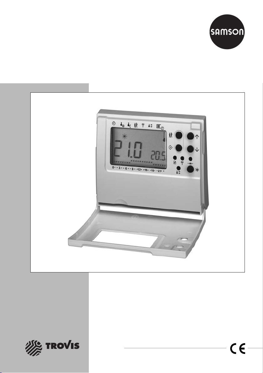
Automation System TROVIS 5500
Room Controller
TROVIS 5572
Electronics from SAMSON
Mounting and
Operating Instructions
EB 5572 EN
®
Firmware version 1.10
Edition February 2007
Page 2
Disclaimer of liability
Disclaimer of liability
We areconstantly developing our products and therefore, reservethe right to change the prod
uct or the information contained in this document at any time without notice.
We donot assume any liability for the accuracy or completenessof these mounting and operat
ing instructions. Moreover, we do not guarantee that the buyer can use the product for an in
tended purpose. SAMSON rejects any liability for claims by the buyer, especially claims for
compensation including lost profits or any other financial loss, except the damage was caused
intentionally or by gross negligence. If an essential term of the contract is breached by negli
gence, SAMSON’s liability is limited to the foreseeable damage.
Safety instructions
The device may only be assembled, started up or operated by trained and
4
experienced personnel familiar with the product.
Proper shipping and appropriate storage are assumed.
4
-
-
-
-
2 EB 5572 EN
Page 3

Contents
Contents
1 Operation . . . . . . . . . . . . . . . . . . . . . . . . . . . . . . . 5
1.1 Operating elements. . . . . . . . . . . . . . . . . . . . . . . . . . . 5
1.2 Display . . . . . . . . . . . . . . . . . . . . . . . . . . . . . . . . 6
1.3 Setting the controller time . . . . . . . . . . . . . . . . . . . . . . . . 7
1.4 Programming the time schedule . . . . . . . . . . . . . . . . . . . . . 8
1.5 Selecting the operating mode (presence button) . . . . . . . . . . . . . 9
1.6 Changing temperature set points temporarily . . . . . . . . . . . . . . 10
2 Start-up. . . . . . . . . . . . . . . . . . . . . . . . . . . . . . . . 11
2.1 Activate/deactivate functions . . . . . . . . . . . . . . . . . . . . . 11
2.2 Changing parameters . . . . . . . . . . . . . . . . . . . . . . . . . 12
2.3 Calibrating the room sensor . . . . . . . . . . . . . . . . . . . . . . 13
2.4 Checking inputs and outputs . . . . . . . . . . . . . . . . . . . . . . 14
2.5 Reset to default settings . . . . . . . . . . . . . . . . . . . . . . . . 15
3 Functions . . . . . . . . . . . . . . . . . . . . . . . . . . . . . . . 16
3.1 Heating functions . . . . . . . . . . . . . . . . . . . . . . . . . . . 16
3.1.1 Window contact . . . . . . . . . . . . . . . . . . . . . . . . . . . 16
3.1.2 Optimization . . . . . . . . . . . . . . . . . . . . . . . . . . . . . 16
3.1.3 Vacation period. . . . . . . . . . . . . . . . . . . . . . . . . . . . 17
3.2 Cooling functions . . . . . . . . . . . . . . . . . . . . . . . . . . . 17
3.2.1 Window contact . . . . . . . . . . . . . . . . . . . . . . . . . . . 17
3.2.2 Dew point monitoring . . . . . . . . . . . . . . . . . . . . . . . . . 17
3.3 Operating mode override . . . . . . . . . . . . . . . . . . . . . . . 18
3.4 Summer time/winter time changeover . . . . . . . . . . . . . . . . . 18
3.5 Key lock . . . . . . . . . . . . . . . . . . . . . . . . . . . . . . . 18
3.6 Switching outputs . . . . . . . . . . . . . . . . . . . . . . . . . . . 19
4 Communication . . . . . . . . . . . . . . . . . . . . . . . . . . . . 21
5 Installation . . . . . . . . . . . . . . . . . . . . . . . . . . . . . . 22
6 Electrical connection. . . . . . . . . . . . . . . . . . . . . . . . . . 23
7 Appendix. . . . . . . . . . . . . . . . . . . . . . . . . . . . . . . 24
7.1 Function block list . . . . . . . . . . . . . . . . . . . . . . . . . . . 24
7.2 Parameter list . . . . . . . . . . . . . . . . . . . . . . . . . . . . . 25
7.3 Technical data . . . . . . . . . . . . . . . . . . . . . . . . . . . . 27
EB 5572 EN 3
Page 4
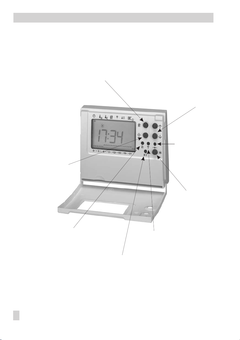
Brief description
Changeover key (short = 1 s)
(time, date, time schedules)
Changeover key (long = 5 s)
(
Set points
parameter level)
Presence button
(Operating mode: Automatic – Time-of-use – Outside time-of-use)
Arrow keys
(scrolling, changing)
Reset key
Default settings
4 EB 5572 EN
Data sheet key
(configuration level)
Thermometer key
(
Control
parameter level)
Radio tower key
(
Communication
Enter key (selecting,
confirming)
parameter level, test)
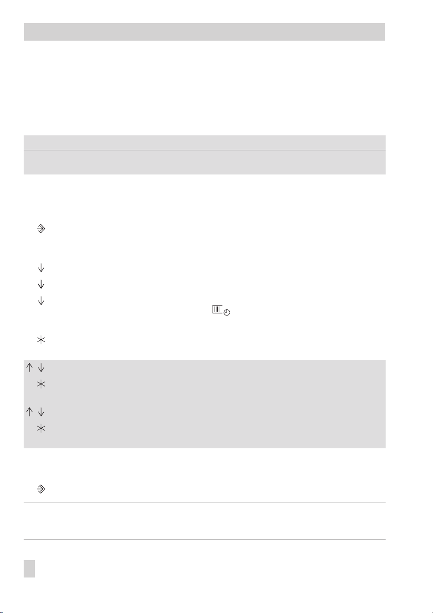
Page 5

Operation
1 Operation
The room controller is ready for use after performing the connections (section 6) and start-up
(section 2).
1.1 Operating elements
Operating elements when cover is closed
Arrow keys (up and down keys)
Used to select displays and parameters
Manual key
Without any function
Additional operating elements accessible with the cover open
Enter key
Used to confirm a selection or setting
Changeover key
Key pressed for approx. 1 sec.: Open controller time and programmed time
schedule
Key pressed for approx. 5 sec.: Open
tering key number)
Presence button
Used to select operating mode (Automatic – Time-of-use – Outside of time-of-use)
Set points
parameter level (only after en-
Note that you require a pointed object such as a ball-point pen in order to press the follow
ing recessed keys:
Thermometer key
Used to access
Radio tower key
Used to access
Data sheet key
Used to access configuration level (only after entering key number)
Reset key
Used to reset the room controller to its default settings (delivery state)
(only after entering key number)
Control
Communication
parameter level (only after entering key number)
parameter level (only after entering key number)
EB 5572 EN 5
-
Page 6

Operation
1.2 Display
Information on the current operation appears on the display of the controller during use:
Set point Large reading
Actual temperature Small reading on the bottom right of the display
The actual temperature reading changes in steps of 0.5 °C.
Operating mode No icon outside of time-of-use
during time-of-use
in vacation mode
Presence Arrow points to indicating that the automatic operating mode has
been interrupted (refer to section 1.5)
Time schedule 5, 6 changes in automatic operating mode depending on the
programmed time schedule: 5 Time-of-use · 6 Outside of time-of-use
555 Continuous time-of-use (automatic operating mode interrupted)
666 Continuously outside of time-of-use (automatic operatingmode
interrupted)
Communication
failure
Control station
intervention
Frost protection Actual temperature (small) blinks on the display when
6 EB 5572 EN
blinks on the display
(only when communication is configured, refer to section 4)
RC appears on the display
(only when communication is configured, refer to section 4)
– Actual room temperature < 5 °C
– Dew-point monitor alarm
– Window contact
Snow flake icon (blinking)
– Actual room temperature < 5 °C
Snow flake icon (constant)
– Dew-point monitor alarm
Page 7

Operation
1.3 Setting the controller time
The correct time and date needs to be set directly after starting up the controller or after the
power supply has been disconnected for more than 24 hours.
How to proceed:
Open the cover.
Press key briefly (approx 1 s). The time appears on the display.
An arrow on the right of the display at the same level as the changeover key indi
cates that the time can be changed.
Press this key to enter the editing mode.
The time starts to blink.
Enter the correct time.
Confirm the time.
Select date setting.
Press this key to enter the editing mode.
The date starts to blink.
Enter the correct date.
Confirm the date.
Select year setting.
Press this key to enter the editing mode.
The year starts to blink.
Enter the correct year.
Confirm the year.
Exit the parameter level.
-
Note!
If no key is pressed within five minutes, the controller display returns to the set point reading.
EB 5572 EN 7
Page 8
Operation
1.4 Programming the time schedule
Three times-of-use can be programmed for each day of the week within which the controller
regulates the room temperature to the
Set point for time-of-use
set the start and stop times of this time-of-use to the identical time.
Parameters
Times-of-use Mon to Fri
Times-of-use Sat and Sun
WE Range of values
08:00 to 20:00
00:00 to 00:00
00:00 to 24:00 h in steps of 15 minutes
00:00 to 24:00 h in steps of 15 minutes
How to proceed:
Open cover.
Press key briefly (approx 1 s). The time appears on the display.
An arrow on the right of the display at the same level as the changeover key indi
cates that the time can be changed.
The date appears on the display.
The year appears on the display.
Select time-of-use setting.
The arrow at the top of display points to .
Reading: 1–7 = daily, 1 = Monday, 2 = Tuesday, …, 7 = Sunday
Press this key to enter the editing mode.
The start time of the first time-of-use appears on the display.
Set the start time (in 15-minute steps).
Confirm the start time.
The stop time of the first time-of-use appears on the display.
Set the stop time (in 15-minute steps).
Confirm the stop time.
The start time of the second time-of-use appears on the display.
. If a time-of-use is not required,
-
Repeat the instructions highlighted in gray to set the second and third times-of-use. After all the
times-of-use have been programmed:
Exit the parameter level.
Note!
If no key is pressed within five minutes, the controller display returns to the set point reading.
8 EB 5572 EN
Page 9

Operation
1.5 Selecting the operating mode (presence button)
Press key repeatedly to cycle through the following operating modes:.
Temporary set point settings (see section 1.6) are reset when the operating mode is changed.
Automatic mode
( during time-of-use, no icon appears outside of time-of-use; 6…5…6)
Depending on the programmed time schedule, the controller regulates the room tem
perature to the
for outside of time-of-use
Set point for time-of-use
outside of the time-of-use.
Time-of-use (;55555…)
The controller regulates the room temperature to the
less of the programmed time schedule.
Outside of time-of-use (66666…)
The controller regulates the room temperature to the
time-of-use
regardless of the programmed time schedule.
The duration of the time-of-use and outside of time-of-use operating mode is set in function
block F02:
Function
Resetting operating mode 1 F02*
* F02 - 0: Operating mode settings for continuous time-of-use/outside of time-of-use
F02 - 1: Operating mode settings for time-of-use/outside of time-of-use that applies until the next
time schedule starts when the operating mode changes back to automatic mode
during the time-of-use and to the
Set point for time-of-use
Set point for outside of
WE Configuration
Set point
regard
-
-
EB 5572 EN 9
Page 10

Operation
1.6 Changing temperature set points temporarily
During the controller operation, the current set point and the actual temperature appear on the
display.
Use the arrow keys to temporarily change the current set point.
The new temporary set pointapplies until the next time-of-use starts or until the operating mode
is changed, however, eight hours at the maximum.
The following maximum set point shifts apply:
Set point for time-of-use
4
Set point for outside of time-of-use:
4
Set point for vacation mode
4
How to proceed:
Change the set point temporarily in steps of 0.5 °C.
Note!
The temporary set point can also be overwritten by a building control station (GLT) when the
communication is active (see section 4).
: ±3 °C
+8 °C
: +8 °C
10 EB 5572 EN
Page 11

2 Start-up
Start-up
The changes described in this section concerning controller configuration can only be per
formed after the valid key number has been entered.
The valid key number is specified on page 27. To prevent unauthorized access to the key num
ber, tear out or blank out the key number.
2.1 Activate/deactivate functions
A function is activated and deactivated by selecting the associated function block.
The function blocks are listed in section 7.1.
How to proceed:
Open cover.
Press the data sheet key.
Enter key number.
The configuration level is opened.
Select the function block.
Enter the editing mode.
Fb : _ _ blinks.
Activate the function block.
Reading: Fb : _ _ ON
or
Deactivate the function block.
Reading: Fb : _ _ OFF
Confirm setting.
Repeat the instructions highlighted in gray to set further function blocks.
On completing the controller configuration:
Exit the configuration level (or, alternatively, by pressing ).
-
-
Note!
If no key is pressed within five minutes, the controller display returns to the set point reading.
EB 5572 EN 11
Page 12

Start-up
2.2 Changing parameters
Depending on the active functions, not all the parameters that are specified in the parameter
lists in the appendix are accessible (–> section 7.2).
The parameters are arranged in topics in various parameter levels (PA):
PA
4
4
4
Set points
PA
Control
PA
Communication
How to proceed:
Open cover.
Select required parameter level:
Enter the key number.
The parameter level is opened.
Select parameter.
Enter the editing mode.
The display starts to blinks.
Set parameter.
Confirm setting.
Repeat the instructions highlighted in gray to set other parameters in the opened parameter
level. On completing all the parameter settings:
Exit the parameter level. Use corresponding key depending on the parameter level:
: Set points for time-of-use, outside of time-of-use, and
vacation mode
: Control parameters
: Device address, Baud rate, sensor calibration, switching
inputs and outputs
Set points
PA
Control
PA
PA
Communication
Set point
PA
Control
PA
PA
Communication
(press key approx. 5 sec.)
s
Note!
If no key is pressed within five minutes, the controller display returns to the set point reading.
12 EB 5572 EN
Page 13

Start-up
2.3 Calibrating the room sensor
If the temperature displayed on the room controller (current temperature on the bottom right of
the display) does not match the actual room temperature, the measured temperature of the
room sensor can be changed and reset. On calibration, the currently displayed sensor temper
ature needs to be changed to match the directlymeasured roomtemperature (referencetemper
ature).
Note!
An incorrectly performed calibration leads to the wrong room temperature measurements and
results in incorrect control performance. Use a thermometer with a high degree of accuracy on
measuring the reference temperature.
How to proceed:
Open cover.
Select
Communication
Enter the key number.
The parameter level is opened.
The device address appears on the display.
The Baud rate appears on the display.
The transmit/receive test appears on the display.
Select correction value for room sensor
Reading: Measured temperature (small); correction value (large)
Enter the editing mode.
The correction value starts to blink.
Set the temperature difference found.
Confirm the temperature difference.
Exit the parameter level (or, alternatively, by pressing ).
parameter level.
-
-
Note!
If no key is pressed within five minutes, the controller display returns to the set point reading.
EB 5572 EN 13
Page 14

Start-up
2.4 Checking inputs and outputs
The current state of the binary inputs, triacs and analog outputs can be displayed in the
munication
How to proceed:
parameter level. The state of triacs andanalog outputscan be changed manually.
Open cover.
Select
Communication
Enter the key number.
The parameter level is opened
Press key 4 times.
The state of the binary input BE1 appears:
E1 0 /E1 1 (BE1 open/closed)
Press the key once to change to the next input or output:
• Binary input BE2 · Reading: E2 0/E2 1 (BE 2 open/closed)
• Triac 1 · Reading: A1 0/A1 1 (triac 1 open/closed)
• Triac 2 · Reading: A2 0/A2 1 (triac 2 open/closed)
• Analog output AA1 · Reading: AA1 0 to AA1 100 (0 to 10 V voltage)
• Analog output AA2 · Reading: AA2 0 to AA2 100 (0 to 10 V voltage)
Changing triac/analog output state:
The output triac 1 (A1), triac 2 (A2), analog output AA1 or analog output AA2 ap
pear on the controller display.
Enter the editing mode.
Close triac (A_ 1) or raise voltage at the analog output.
or
Open TRIAC (A_ 0) or reduce voltage at the analog output.
parameter level.
Com
-
-
Exit the parameter level (or, alternatively, by pressing ).
Note!
If no key is pressed within five minutes, the controller display returns to the set point reading.
14 EB 5572 EN
Page 15

2.5 Reset to default settings
All parameters and functions can be reset to their default settings.
How to proceed:
Open cover.
Select default setting menu.
Enter the key number.
The default setting menu is opened.
Enter the editing mode.
Press key.
Confirm the reset.
Exit the default setting menu.
Start-up
EB 5572 EN 15
Page 16

Functions
3 Functions
3.1 Heating functions
3.1.1 Window contact
The window contact function depends on the state of binary input BE1:
BE1 = 0: The heating valve is closed.
4
BE1 = 1: Control according to the current operating mode.
4
The heating valve is opened for five minutes every 20 minutes
3.1.2 Optimization
The controller determines the
building characteristics.
Advance heating time
The
time-of-use
when the time-of-use starts, but at an earlier point in time instead.
The
side of time-of-use
finish when the outside of time-of-use starts, but at an earlier point in time instead.
Note!
Advance heating time
time
Function
Optimization 0 F03 - 1
Parameters
Maximum advance heating time 360 min PA
Maximum cooling down time 120 min PA
already when the time-of-use starts. In optimization mode, heating does not start
Cooling down time
already when the time-of-use ends. In optimization mode, heating does not
and
Maximum cooling down time
Advance heating time
is the time required to achieve the room temperature
is the time required to achieve the room temperature
and
Cooling down time
parameters respectively.
WE Configuration
WE Parameter level / Range of values
and
Cooling down time
are restricted by the
Set points
Set points
Maximum advance heating
/ 0 to 360 min
/ 0 to 120 min
depending on the
Set point for out-
Set point for
16 EB 5572 EN
Page 17

3.1.3 Vacation period
Functions
During the programmed
perature to the
The Presence alert function (section 3.3) isnot activeduring the programmed vacation period.
Parameters
Set point for vacation mode 15 °C PA
Vacation schedule – PA
Set point for vacation mode
Vacation period
WE Parameter level / Range of values
(start and stop), the controller regulates the room tem
. appears on the display.
Set points
Set points
/ 5 to 30 °C
/ –
3.2 Cooling functions
The cooling valve regulates the temperature to the current set point during the time-of-use.
The following applies for outside of time-of-use:
When F04 - 0: No cooling
When F04 - 1: The temperature is regulated to a raised set point. The setback calculated
from the set point for outside of time-of-use during heating is interpreted
as an increase.
Function
Cooling 0 F04*
* F04 - 0: No cooling outside of time-of-use
F04 - 1: Cooling also outside of time-of-use
WE Configuration
3.2.1 Window contact
The Window contact function depends on the state of binary input BE1:
BE1 = 0: The cooling valve is closed.
4
BE1 = 1: Control according to the current operating mode.
4
-
3.2.2 Dew point monitoring
The dew point monitoring uses the binary input BE2:
BE2 = 0: Temperature regulated to
4
BE2 = 1: Cooling is interrupted.
4
Function
Function BE2 0 F01 - 1
Set point for outside of time-of-use
WE Configuration
.
EB 5572 EN 17
Page 18

Functions
3.3 Operating mode override
The adjusted operating mode override is processed by binary input BE2:
BE2 = 0: Control according to the current operating mode.
4
BE2 = 1: The temperature is regulated to
4
Note!
If the vacation mode is set, the setting F01 - 1 has no function; the controller continues to regu
late the temperature to
programmed time schedule or operating mode.
Set point for vacation mode.
Set point for time-of-use
regardless of the
-
Function
Function BE2 0 F01 - 0
WE Configuration
3.4 Summer time/winter time changeover
The time changeover is performed automatically on the last Sunday in March at 02:00 h and on
the last Sunday in October at 03:00 h.
Function
Summer time/winter time changeover 1 F06 - 1
WE Configuration
3.5 Key lock
When this function is active, , , , and keys do not have any function.
Just theset point and actual temperature appear on thecontroller display. Changes to the oper
ating mode and time schedule and temporary set point changes cannot be made.
Function
Key lock 0 F05 - 1
WE Configuration
-
18 EB 5572 EN
Page 19

3.6 Switching outputs
Functions
The operating mode of the switching outputs can be selected in the
Control
parameter level.
Note!
Changes to the control signal that are smaller than the value set in
parameter
Parameter
Min. control signal 5 % PA
are not processed.
WE Parameter level / Range of values
Control
/ 1 to 100 %
Min. control signal
Three-point stepping output (heating only)
The control loop functions with a PI control algorithm. The heating valve reacts to pulses which
the controllerissues when a system deviation exists. Inparticular, the length of the first pulsedepends on the size of the system deviation and the selected
rises). Pulse length and interval time change continuously until the system deviation is
as K
P
Gain K
eliminated. The interval between pulses is influenced considerably by the
terval increases as T
rises). The
N
Valve transit time T
indicates how long the valve needs to
Y
(the pulse length increases
P
Reset time T
(the in-
N
move through the range from 0 to 100 %.
Parameters
Switching outputs function 1
Gain K
P
Reset time T
Valve transit time T
N
Y1
WE Parameter level / Range of values
PA
Control
/ Select: 1
1.0 PA
180 s PA
45 s PA
Control
Control
Control
/ 0.1 to 100
/ 0 to 1000 s
/ 0 to 1000 s
2 x On/off PPM (heating and cooling)
The control signals applied at the 0to 10 Voutput that exceedthe value enteredin the
control signal
1/T
Y1
Parameters
Switching outputs function 1
Valve transit time T
Valve transit time T
parameter, are issued as a pulse width modulated signal with the basic frequency
(heating) or 1/TY2(cooling).
WE Parameter level / Range of values
PA
Control
/ Select: 2
Y1
Y2
45 s PA
45 s PA
Control
Control
/ 0 to 1000 s
/ 0 to 1000 s
EB 5572 EN 19
Minimum
Page 20

Functions
2 x On-off thermostat (heating and cooling)
The output signal (AA1 heating, AA2 cooling) of the controller is switched on or off.
A control signal is issued when the temperature exceeds or falls below the set point, depending
on the controlled variable. If the control signal exceeds the
Min. Control signal
, the on-off ther
mostat is switched on or off.
Parameter
Switching outputs function 1
WE Parameter level / Range of values
PA
Control
/ Select: 3
Triac 1 and triac 2 switched according to the time schedule
Both triacs are switched on together depending on the time schedule or the adjusted operating
mode. Both triacs are closed outside of time-of-use.
Parameter
Switching outputs function 1
WE Parameter level / Range of values
PA
Control
/ Select: 4
Triac 1 switched according to the time schedule, triac 2 switched according the state of
AA2
Triac 1 switches according to the time schedule or adjusted operating mode.
Triac 2 switches on when the control signal for cooling = 100 % and when a system deviation
(cooling demand) continues to exist. Triac 2 functions in sequence to the control signal for cooling, for example, to connect additional cooling equipment. When the temperature reaches the
set point, triac 2 switches off again.
Parameter
Switching outputs function 1
WE Parameter level / Range of values
PA
Control
/ Select: 5
-
20 EB 5572 EN
Page 21

4 Communication
Communication
The serialsystem bus interface RS-485 enables the TROVIS 5572 Room Controller tocommuni
cate with a control system (GLT). A complete control system can be implemented using a suit
able software to visualize the process and to enable communication.
The operation of the controller requires a constant bus link (data cable).The bus line is designed
in an open ring structure to connect individual control equipment. The data cable is connected
at the end of the bus lineto thecontrol station over a RS-485/RS-232 converter (e.g.CoRe 01).
The bus connection range (cable length) is maximum 1200 m. A maximum of 128 devices can
be connected in such a segment. Repeaters must be used (for example, CoRe 01) to regenerate
the signal level over long distances or when more than 32 devices are connected to one bus
line. A maximum of 246 devices can be addressed and connected to a bus with 8-bit
addressing.
Caution!
You are required to follow the relevant standards and regulations applicable to lightning and overvoltage protection on installing the controller.
A transmitting and/or receiving test can be initiated in the
RC blinking : Receiving data telegrams from control station (GLT),
4
on the display even when they are intended for other controllers
: Controller transmitting to control station (GLT)
4
Description of the parameters that need to be set:
Device address
The
within a system.
Baud rate
The
is used to identify the controller. An address may only be assigned once
indicates the transfer rate between control systemand controllerin a bus system.
Communication
parameter level:
-
-
Functions
16-bit addressing 0 F07*
* F07 - 0: 8-bit addressing
F07 - 1: 16-bit addressing
WE Configuration
EB 5572 EN 21
Page 22

Installation
Parameters
Device address 000 PA
Baud rate 19200 PA
Transmitting/receiving test – PA
WE Parameter level / Range of values
Communication
Communication
Communication
/ 0 to 255 ( 8 bit)
0 to 999 (16 bit)
/ 19200, 9600
/ Display: RC/
5 Installation
Note!
The room controller must be mounted at a height of 1.50 m.
Make sure that the operation of the room controller is not affected by heat sources (radiators,
lights, electrical appliances) or by drafts close to doors or windows.
The room controller should not be covered by curtains or any pieces of furniture.
To mount and wire the room controller, remove the housing from the base.
How to proceed:
1. Press down the tongue on the bottom of the controller and tip the housing section forward to remove it from the base.
2. Screw the base to the wall.
3. Connect the wiring as described in section 6.
4. Push the top of the housing section onto the base and push it down.
22 EB 5572 EN
Page 23

6 Electrical connection
Important!
The room controller is operated with a 24 V AC power supply.
Terminal assignment
Electrical connection
1
2
3 0…10 V output 1
4 0…10 V output 2
5 GND for 0…10 V outputs
6 Binary input BE1
7 Binary input BE2
8 GND for binary inputs
9
10 AC 2 has GND reference
11
12
13
14
15
16
Modbus RS-485 (slave)
Power supply 24 V AC
Triac output 1 24 V AC, 1 A
Triac output 2 24 V AC, 1 A
RS-485; Modbus (master) Connection to expansion module(s)
Connection to the control station (GLT) or
to a Modbus master interface
AC 1
EB 5572 EN 23
Page 24

Appendix
7 Appendix
7.1 Function block list
F Function block WE Description
01 Function BE2 0 F01 - 0: Operating mode override by BE2
F01 - 1: Dew point monitoring
02 Resetting the operating
mode
03 Optimization 0 F03 - 0: Function is not active
04 Cooling 0 F04 - 0: Cooling not active outside of time-of-use
05 Key lock 0 F05 - 0: Function is not active
06 Summer time/winter
time changeover
07 16-bit addressing 0 F07 - 0: 8-bit addressing
1 F02 - 0: Time-of-use/outside of time-of-use operating
mode setting continuous
F02 -1 : Time-of-use/outside of time-of-use operating
mode setting that applies until the next time
schedule starts when the operating mode changes
back to automatic mode
F03 - 1: Optimization; calculation of advance heating time
or cooling down time in heating mode
F04 - 1: Cooling also active outside of time-of-use
F05 - 1: Keys (except for recessed keys) are locked
1 F06 - 0: Function is not active
F06 - 1: Automatic time changeover
F07 - 1: 16-bit addressing
24 EB 5572 EN
Page 25

7.2 Parameter list
Appendix
Set points
parameter level
Parameter WE Description
01 Set point for time-of-use 21 °C Adjustment range: 5 to 30 °C
02 Set point for outside of
17 °C Adjustment range: 5 to 30 °C
time-of-use
03 Set point for vacation
15 °C Adjustment range: 5 to 30 °C
mode
04 Maximum advance
heating time
360 min Start value for the calculation: 120 min
Can only selected when the optimization function is active
(F03 - 1).
05 Maximum cooling
down time
120 min Start value for the calculation: 60 min
Can only selected when the optimization function is active
(F03 - 1).
06 Vacation schedule –
Control
parameter level
Parameter WE Description
01 Switching outputs
function
1
Option:
1: Three-point stepping output
2: 2 x On/off PPM
3: 2 x On/off thermostat
4: Triac 1 and triac 2 switched according to the time schedule
5: Triac 1 switched according to the time schedule;
Triac 2 switched acc. to the state of triac 1 and AA2
02 Gain K
03 Reset time T
P
N
04 Derivative-action time T
05 Valve transit time T
06 Valve transit time T
Y1
Y2
1.0 Adjustment range: 0.1 to 100
180 s Adjustment range: 0 to 1000 s
0 s Adjustment range: 0 to 1000 s
V
45 s Adjustment range: 0 to 1000 s
45 s Adjustment range: 0 to 1000 s
07 Min. control signal 5.0 % Adjustment range: 1.0 to 100 %
EB 5572 EN 25
Page 26

Appendix
Communication
Parameter WE Description
01 Device address 0 Adjustment range: 0 to 255 (8 bit) 0 to 999 (16 bit)
02 Baud rate 19200 Adjustment range: 9600, 19200
03 Transmitting/receiving
test
04 Calibrating the room
sensor
05 Read/test BE1 Reading: E1 0 (open), E1 1 (closed)
06 Read/test BE2 Reading: E2 0 (open), E2 1 (closed)
07 Read/test triac 1 Reading/Adjustment range: A1 0 (open), A1 1 (closed)
08 Read/test triac 2 Reading/Adjustment range: A2 0 (open), A2 1 (closed)
09 Read/test AA1 Reading/Adjustment range: AA1 0 (0 V) to AA1 100 (10 V)
10 Read/test AA2 Reading/Adjustment range: AA2 0 (0 V) to AA2 100 (10 V)
parameter level
000 = No communication with control station (GLT)
RC blinks on display on receiving any data telegram from the
control station(GLT), even if they are intended for other con
trollers
blinks on display for transmitting to the control station
(GLT)
0.0 Adjustment range: –9.9 to + 9.9 °C (in steps of 0.1 °C)
-
26 EB 5572 EN
Page 27

7.3 Technical data
Inputs 1 room sensor (internal)
1 presence button (internal)
2 binary inputs for window contact/dew point and operating mode
override
Outputs 2 triac outputs 24 V AC, 1 A
2 outputs 0 to 10 V
Power supply 24 V AC
Interface Modbus (RS-485)
Environmental conditions Operation: 0 to 50 °C
Degree of contamination 2 according to VDE 0110
Noise immunity According to EN 61000-6-1
Noise emission According to EN 61000-6-3
Power consumption
of room controller
Power consumption
of expansion module
Maximum load for
analog output
Dimensions in mm
W x H x D 113 x 91 x 30
Storage, transportation: –10 to 60 °C
95 % rH, not condensing
Approx. 0.6 VA
Approx. 1 VA
Not smaller than 4.7 k
Ω
Appendix
Key number:
1732
EB 5572 EN 27
Page 28

Terminal assignment (refer to section 6)
Please note:
The room controller is operated with 24 V AC.
Modbus RS-485
to expansion module
RS-485; Modbus (slave)
0 … 10 V output 1
0 … 10 V output 2
GND for 0 … 10 V outputs
Binary input BE1
Binary inputs BE2
GND for binary inputs
Power supply 24 V AC
Triac output 1
Triac output 2
RS-485; Modbus (master)
Connection to the control
station (GLT) or to a
Modbus master interface
AC 1
AC 2 has GND reference
24 V AC, 1 A
24 V AC, 1 A
Connection to expansion
module(s)
SAMSON AG · MESS- UND REGELTECHNIK
Weismüllerstraße 3 · 60314 Frankfurt am Main · Germany
Phone: +49 69 4009-0 · Fax: +49 69 4009-1507
Internet: http://www.samson.de
EB 5572 EN
2007-02
 Loading...